

Page 1

1
Petrol snow thrower
Petrol snow thrower
SPT-182-570
SPT-270-720
SPT-302-720
GB
Original instructions
Übersetzung der Originalanleitung
Alkuperäisten ohjeiden käännös
D
FIN
Algupärase kasutusjuhendi tõlge
EE
Page 2

2
Manufactured under license by:
MATRIX GmbH • Postauer Straße 26 • D-84109 Wörth/Isar • www.matrix-direct.net
Stanley is a registered trademark of The Stanley Works or its affiliates and is used under license.
GB
Toodetud litsentsi alusel:
MATRIX GmbH·Postauer Straße·26 D-84109 Wörth/Isar·www.matrix-direct.net
Stanley® on The Stanley Worksi või selle sidusettevõtete registreeritud kaubamärk ning seda kasutatakse
litsentsi alusel.
EE
Hergestellt unter Lizenz durch:
MATRIX GmbH·Postauer Straße·26 D-84109 Wörth/Isar·www.matrix-direct.net
Stanley® ist ein eingetragenes Warenzeichen von The Stanley Works oder seinen Tochterunternehmen
und wird unter Lizenz verwendet
D
Lisenssillä valmistanut:
MATRIX GmbH·Postauer Straße·26 D-84109 Wörth/Isar·www.matrix-direct.net
Stanley® on The Stanley Works -yhtiön tai sen tytäryhtiöiden rekisteröity tavaramerkki ja sitä käytetään
lisenssillä.
FIN
Page 3
3
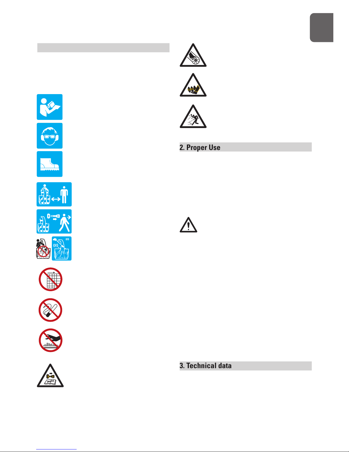
1. Notes on Safety and Warnings
The rating plate on your machine may
show symbols. These represent important
information about the product or instructions
on its use.
Read these instructions for use
carefully.
Wear eye protection.
Wear hearing protection.
Wear safety footwear.
Keep bystanders away.
Stop engine and remove ignition
key prior to leaving the operator’s
position.
Only use clean-out tool to clear
blockage. Never use your hands.
It is forbidden to remove or tamper
with the protection devices and
safety devices.
Do not smoke or have open flames.
Do not touch a hot muffler, gear
housing or cylinder.
Stop engine, remove key, read
manual before making any repairs
or adjustments.
G
B
Keep hands out of the inlet and
discharge openings while machine
is running.
Stay away from rotating augers.
Never direct discharge towards
persons or property.
2. Proper Use
Your new snow thrower will more than satisfy
your expectations. It has been manufactured
under stringent quality standards to meet
superior performance criteria. You will find it
easy and safe to operate, and with proper care, it
will give you many years of dependable service.
Carefully read through this entire operator’s
manual before using your new snow
thrower. Take special care to heed the
cautions and warnings.
Your snow thrower has many features that
will make your job faster and easier. Safety,
performance, and dependability have been
given to top priority in the development of this
machine, making it easy to maintain and operate.
The Engine manufacturer is responsible
for all engine-related issues with regards to
performance, power rating, specifications,
warranty and service. Please refer to the Engine
Manufacturer’s owner’s/operator’s manual,
packed separately with your unit, for more
information.
3. Technical data
SPT-182-570:
Engine type: OHV ,Four-stroke engine, air cooling ;
182cc
Page 4

4
Engine power: 4.0 kW
Max Power: 4,5kW, 6 HP
Starting System: 230V electric start (Optional)
Fuel Tank Capacity: 3.0L
Clearing Width 57 cm
Intake Height 53.5cm
Auger Dia. 30.0cm
Impeller Dia. 30.0cm
Speed 6F+2R
SPT-270-720 :
Engine type: OHV ,Four-stroke engine, air cooling ;
270cc
Engine power: 5,3 kW
Max Power: 6,7kW, 9 HP
Starting System: 230V electric start (Optional)
Fuel Tank Capacity: 6.0L
Clearing Width 72 cm
Intake Height 53.5 cm
Auger Dia. 30.0cm
Impeller Dia. 30.0cm
Speed 6F+2R
SPT-302-720 :
Engine type: OHV ,Four-stroke engine, air cooling ;
302cc
Engine power: 6,2 kW
Max Power: 7,5kW, 10 HP
Starting System: 230V electric start (Optional)
Fuel Tank Capacity: 4.0L
Clearing Width 72 cm
Intake Height 53.5 cm
Auger Dia. 30.0cm
Impeller Dia. 30.0cm
Speed 6F+2R
4. Notes on Safety
General Safety Rules
Understand your machine
Allow operation only by properly trained adult,
never children.
Read and understand the operator’s manual
and labels affixed to the machine. Learn its
application and limitations as well as the
specific potential hazards peculiar to it.
Be thoroughly familiar with the controls and
their proper operation. Know how to stop the
machine and disengage the controls quickly.
Make sure to read and understand all the
instructions and safety precautions as outlined
in the Engine Manufacturer’s Manual, packed
separately with your unit. Do not attempt to
operate the machine until you fully understand
how to properly operate and maintain the
Engine and how to avoid accidental injuries
and/or property damage.
Work area
Never start or run the engine inside a closed
area. The exhaust fumes are dangerous,
containing carbon monoxide, an odorless and
deadly gas. Operate this unit only in a well
ventilated outdoor area.
Never operate the machine without good
visibility or light.
Never operate the machine on a steep slope.
Personal safety
Do not operate the machine while under the
influence of drugs, alcohol, or any medication
that could affect your ability to use it properly.
Dress properly. Wear heavy long pants, boots
and gloves. Do not wear loose clothing, short
pants, and jewelry of any kind. Secure long
hair so it is above shoulder level. Keep your
hair, clothing and gloves away from moving
parts. Loose clothes, jewelry or long hair can
be caught in moving parts.
Use safety equipment. Always wear eye
protection. Safety equipment such as a dust
mask, hard hat, or hearing protection used for
appropriate conditions will reduce personal
injuries.
G
B
Page 5

5
Check your machine before starting it. Keep
guards in place and in working order. Make
sure all nuts, bolts, etc. are securely tightened.
Disengage all clutches and shift into neutral
before starting the engine.
Never operate the machine when it is in need
of repair or is in poor mechanical condition.
Replace damaged, missing or failed parts
before using it. Check for fuel leaks. Keep the
machine in safe working condition.
Never tamper with safety device. Check their
proper operation regularly.
Do not use the machine if the engine’s throttle
control does not turn it on or off. Any gasoline
powered machine that can not be controlled
with the engine throttle control is dangerous
and must be replaced.
Form a habit of checking to see that keys
and adjusting wrenches are removed from
machine area before starting it. A wrench or
a key that is left attached to a rotating part of
the machine may result in personal injury.
Stay alert, watch what you are doing and use
common sense when operating the machine.
Do not overreach. Do not operate the machine
while barefoot or when wearing sandals or
similar lightweight footwear. Wear protective
footwear that will protect your feet and
improve your footing on slippery surfaces.
Keep proper footing and balance at all times.
This enables better control of the machine in
unexpected situations.
Avoid accidental starting. Be sure the engine’s
throttle control is off before transporting the
machine or performing any maintenance or
service on the unit. Transporting or performing
maintenance or service on a machine with its
throttle control on invites accidents.
Fuel safety
Fuel is highly flammable, and its vapors can
explode if ignited. Take precautions when
using to reduce the chance of serious personal
injury.
When refilling or draining the fuel tank, use
an approved fuel storage container while in
a clean, well-ventilated outdoor area. Do not
smoke, or allow sparks, open flames or other
sources of ignition near the area while adding
fuel or operating the unit. Never fill fuel tank
indoors.
Keep grounded conductive objects, such as
tools, away from exposed, live electrical parts
and connections to avoid sparking or arcing.
These events could ignite fumes or vapors.
Always stop the engine and allow it to cool
before filling the fuel tank. Never remove
the cap of the fuel tank or add fuel while the
engine is running or when the engine is hot.
Do not operate the machine with known leaks
in the fuel system.
When practical, remove the machine from the
truck or trailer and refuel it on the ground. If
this is not possible, then refuel the machine on
a trailer with a portable container, rather than
from a fuel dispenser nozzle.
Loose the fuel tank cap slowly to relieve any
pressure in the tank.
Keep the nozzle in contact with the firm of the
fuel tank or container opening at all times until
fueling is complete. Do not use a nozzle lockopen
device.
Never over fill fuel tank. Fill tank to no more
than 12.5mm (1/2”) below the bottom of the
filler neck to provide space for expansion as
the heat of the engine and/or sun cause fuel
to expand.
G
B
Page 6

6
Replace all fuel tank and container caps
securely and wipe up spilled fuel. Never
operate the unit without the fuel cap securely
in place.
Avoid creating a source of ignition for spilled
fuel. If fuel is spilled, do not attempt to start
the engine but move the machine away
from the area of spillage and avoid creating
any source of ignition until fuel vapors have
dissipated. Serious personal injury can occur
when fuel is pilled on yourself or your clothes
which can ignite. Wash your skin and change
clothes immediately.
Store fuel in containers specifically designed
and approved for this purpose.
Never fill containers inside a vehicle or on a
truck or trailer bed with a plastic liner. Always
place containers on the ground away from
your vehicle before filling.
Store fuel in a cool, well-ventilated area.
Safely away from sparks, open flames or other
sources of ignition.
Never store fuel or machine with fuel in the
tank inside a building where fumes may
reach a spark, open flame, or other sources
of ignition, such as a water heater, furnace,
clothes dryer and the like. Allow the engine to
cool before storing in any enclosure.
Machine use and care
Never pick up or carry a machine while the
engine is running.
Do not force the machine. Use the correct
machine for your application. The correct
machine will do the job better and safer at the
rate for which it was designed.
Do not change the engine governor settings
or over-speed the engine. The governor
controls the maximum safe operating speed
of the engine.
Do not put hands or feet near rotating parts.
Avoid contact with hot fuel, oil, exhaust fumes
and hot surfaces. Do not touch the engine or
muffler. These parts get extremely hot from
operation. They remain hot for a short time
after you turn off the unit. Allow the engine
to cool before doing maintenance or making
adjustments.
After striking a foreign object, stop the
engine, remove the wire from the spark
plug, thoroughly inspect the machine for
any damage, and repair the damage before
restarting and operating the machine.
If the machine should start to make an unusual
noise or vibration, immediately shut off the
engine, disconnect the spark plug wire, and
check for the cause. Unusual noise or vibration
is generally warning of trouble.
Use only attachments and accessories
approved by the manufacturer. Failure to do
so can result in personal injury.
Maintain the machine. Check for misalignment
or binding of moving parts, breakage of parts
and any other condition that may affect the
machine’s operation. If damaged, have the
machine repaired before use. Many accidents
are caused by poorly maintained equipment.
Keep the engine and muffler free of grass,
leaves, excessive grease or carbon build up to
reduce the chance of a fire hazard.
Never douse or squirt the unit with water or
any other liquid. Keep handles dry, clean and
free from debris. Clean after each use.
Observe proper disposal laws and regulations
for gas, oil, etc. to protect the environment.
Store idle machine out of the reach of children
and do not allow persons unfamiliar with
G
B
Page 7

7
the machine or these instructions to operate
it. Machine is dangerous in the hands of
untrained users.
Service
Before cleaning, repair, inspecting, or adjusting
shut off the engine and make certain all
moving parts have stopped. Always make
sure the engine’s throttle control is in its STOP
position. Disconnect the spark plug wire, and
keep the wire away from the plug to prevent
accidental starting.
Have your machine serviced by qualified repair
personnel using only identical replacement
parts. This will ensure that the safety of the
machine maintained.
Specific Safety Rules
Do not operate without wearing adequate
winter outer garments.
Do not use the machine on a roof.
Do not run the engine indoors, except when
starting the engine and for transporting
the snow thrower in or out of the building.
Open the outside doors; exhaust fumes are
dangerous.
Always check overhead and side clearances
carefully before operation. Always be aware of
traffic when operating along streets or curbs.
Thoroughly inspect the area to be worked.
Keep the working area clean and free of toys,
doormats, newspapers, sleds, boards, wires
and other foreign objects, which could be
tripped over or thrown by the auger/impeller.
Check for weak spots on docks, ramps or
floors.
Plan your snow-throwing pattern to avoid
discharge toward people or areas where
property damage can occur.
Do not operate near drop-offs, ditches, or
embankments. Machine can suddenly turn
over if a wheel is over the edge of a cliff or
ditch, or if an edge caves in.
Keep all bystanders, children, and pets at least
23m (75 feet) away. If you are approached,
stop the unit immediately.
Use a grounded three-wire extension cord and
receptacle for all machines with electric start
engines.
Check clutch and brake operation frequently.
Adjust and service as required. All motion of
drive wheels and auger/impeller must stop
quickly when control levers are released.
Let engine and machine adjust to outdoor
temperature before starting to clear snow.
Stay alert for hidden hazards or traffic.
Do not overload machine capacity by
attempting to clear snow at too fast of a rate.
Do not throw snow any higher than necessary.
Adjust auger housing height to clear gravel
or crushed rock surfaces. Exercise extreme
caution when operating.
Exercise caution to avoid slipping or falling,
especially when operating in reverse. Never
operate machine at high transport speeds
on slippery surfaces. Always look down and
behind before and while backing.
Do not operate on steep slopes. Do not
clear snow across the face of slopes. Keep
all movement on slopes slow and gradual.
Do not make sudden changes in speed or
direction. Use a slow speed to avoid stops or
shifts on slopes. Avoid starting or stopping
on a slope. Do not park machine on a slope
unless absolutely necessary. When parking on
G
B
Page 8

8
a slope, always block the wheels.
Disengage power to the auger/impeller when
transporting or not in use.
Disengage all control levers and stop engine
before you leave the operating position
(behind the handles). Wait until the auger/
impeller comes to a complete stop before
unclogging the chute assembly, making any
adjustments, or inspections.
Hand contact with the rotating impeller inside
the discharge chute is the most common
cause of injury associated with snow throwers.
Do not unclog chute assembly while engine
is running. Shut off engine and remain behind
handles until all moving parts have stopped
before unclogging. Never put your hand in
the discharge or collector openings. Always
use the clean-out tool provided to unclog the
discharge opening.
G
B
Page 9
9
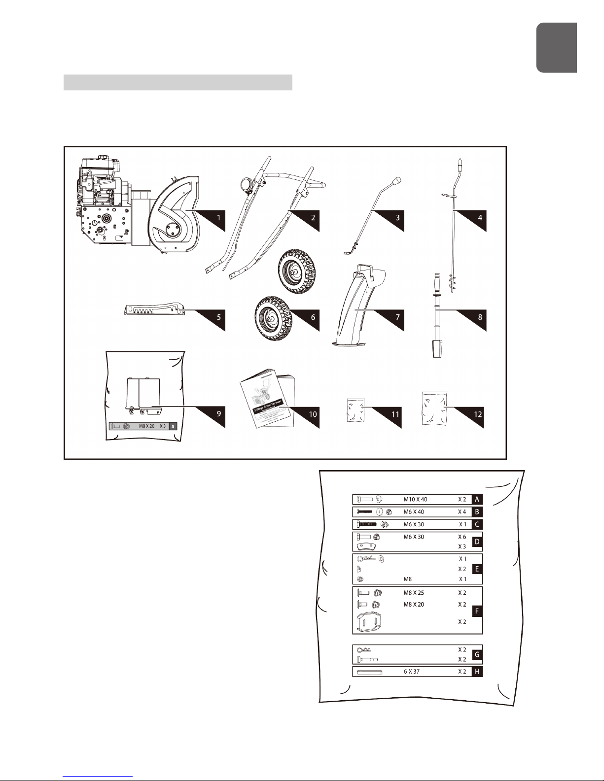
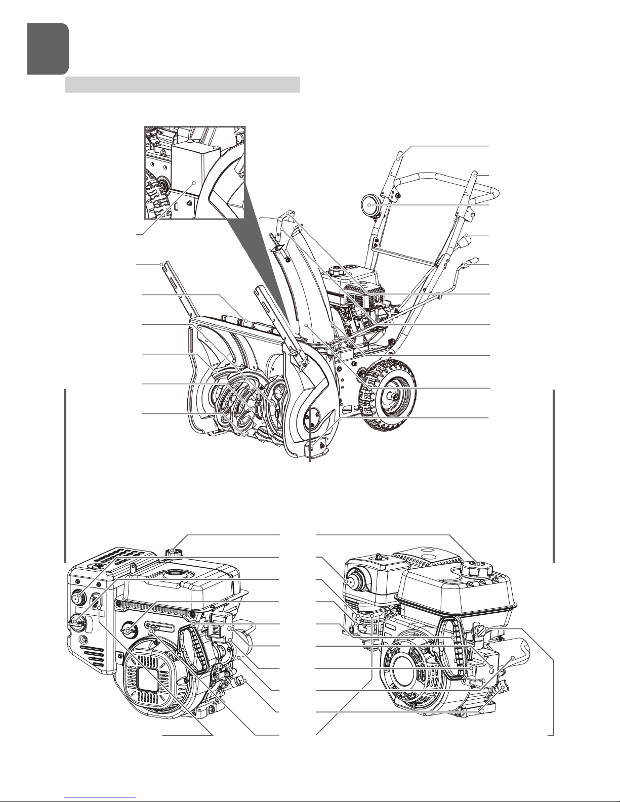
5. Overview Instrument Components
The snow thrower comes partially assembled and is shipped in carefully packed carton. After all
the parts have been removed from the carton, you should have:
Attention : All reference to the left or right side
of the snow thrower are from the
operator’s position.
1. Snow Thrower Unit
2. Handlebars
3. Shift Lever
4. Chute Crank Lever
5. Control Panel
6. Wheels (1 pair)
7. Discharge Chute
8. Chute Clean-Out Tool
9. Battery (if so equipped)
10. Operator’s Manual & Engine Manual
11. Engine Hardware Bag
12. Snow Thrower Hardware Bag, Including
G
B
Page 10
10
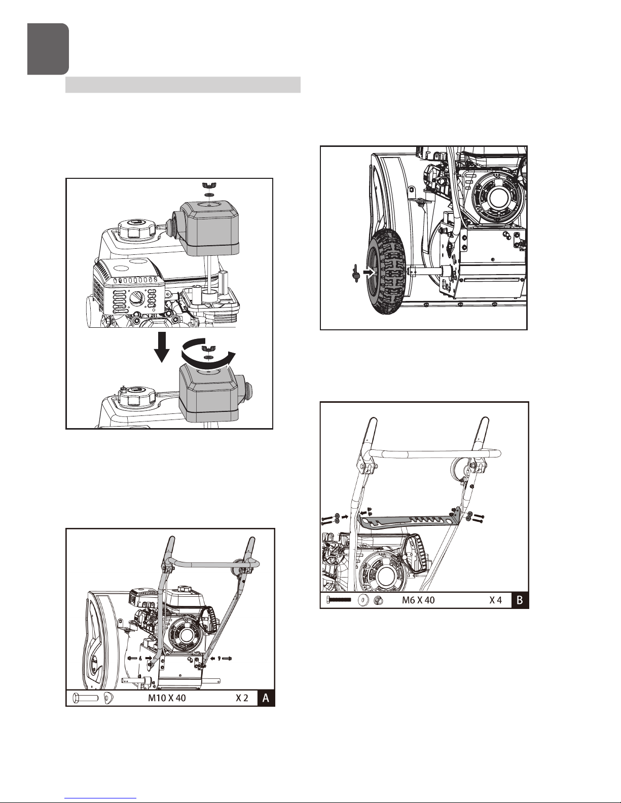
6. Assembly
Following the assembly directions below, you will
assemble the snow thrower in a few minutes
Engine
1. Remove wing nut and washer from the air
filter cover.
2. Rotate the air filter cover by 180o so that
the primer faces outside.
3. Install air filter cover and tighten wing nut.
Handlebars
1. Align the holes in the handlebars with the
side plates and secure handlebars with
the screws and the washers until they are
finger tight.
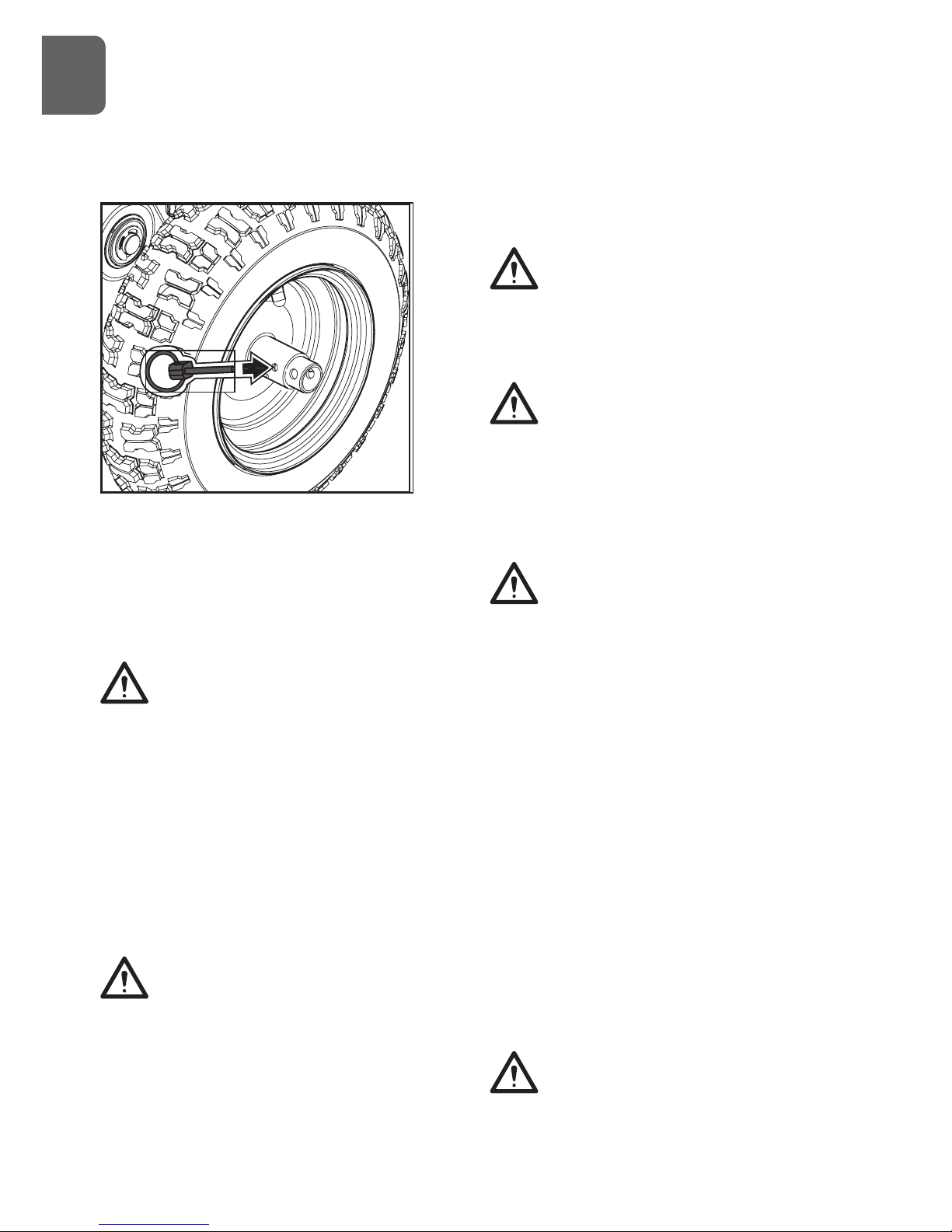
2. Remove the axle pins and slide the wheels
on the axle. Insert each axle pin through
the hole in each wheel hub and through the
hole in the axle.
3. Secure control panel to the handlebars with
screws, washers and nuts until they are
finger tight.
4. Ensure that the handles are at the same
height, and then tighten all the fasteners
securely.
G
B
Page 11
11
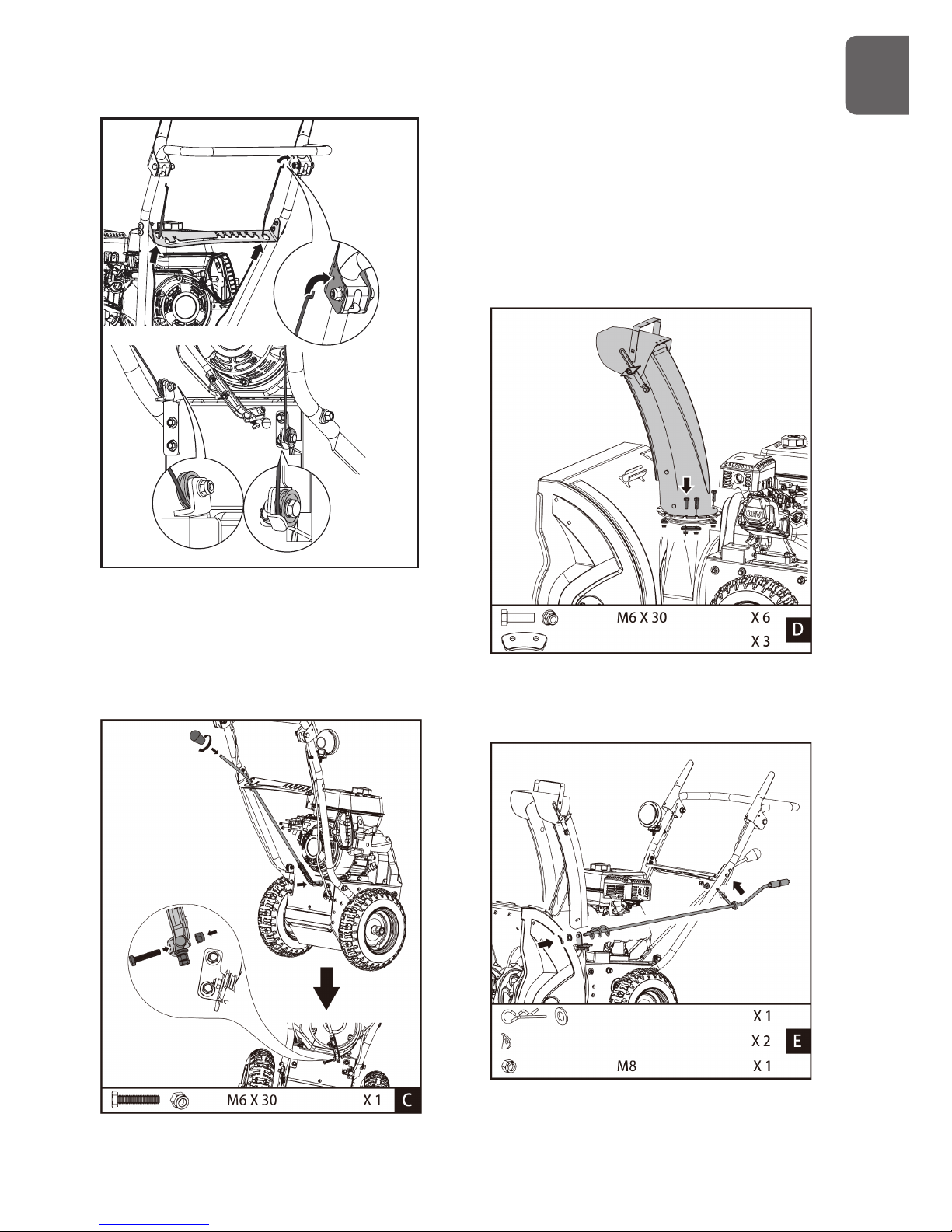
5. Slide the control cables through the holes in
the control panel. Make certain the cables are
seated properly in roller guides when hook the
cables to the clutch levers.
Speed Shift Linkage
Remove the knob to slide the shift lever
through the slot in the control panel. Secure
shift lever to the shift arm with screw and nut.
Replace the knob.
Discharge Chute
1. Grease underside of discharge chute ring (if
not already greased).
2. Install discharge chute over opening in the
auger housing and secure with fasteners.
G
B
Page 12
12
3. Secure the upper crank lever bracket (attached
to the crank lever) to the upper left side of the
handlebar with a locknut and two curved washers.
4. Apply grease to the spiral of the crank lever.
5. Insert the spiral end of the crank lever into the
lower bracket and secure with the flat washer and
clevis pin.
Tires
The tires are over-inflated at factory for
shipping purposes. Check the pressure in the
tires. Reduce or Increase equally in both tires
to the manufacturer’s recommended pressure.
Under any circumstance do not
exceed manufacturer’s recommended
pressure. Excessive pressure when
seating beads may cause tire/rim assembly
to burst with force sufficient to cause serious
injury. Refer to side wall of tire for recommended
pressure.
Equal tire pressure should be maintained
at all times. If the tire pressure is not
equal in both tires, the machine may not
travel in a straight path and the scraper
blade may wear unevenly.
Keep tires free of gasoline and oil,
which can harm rubber.
Skid Shoes
1. Move the machine to a level surface.
2. Support the auger blades so that they are 3mm
(1/8”) off the ground.
3. Check the scraper blade adjustment. The scraper
blade should be 3mm (1/8”) above and parallel to
a level ground. To adjust the scraper blade, loosen
the seven mounting screws (two on each side),
level the scraper blade, and tighten the mounting
screws.
4. Attach both skid shoes to the auger side plates
with the screws and nuts. Move the skid shoes
down as far as possible. Be sure both skid shoes
are adjusted evenly. Tighten securely.
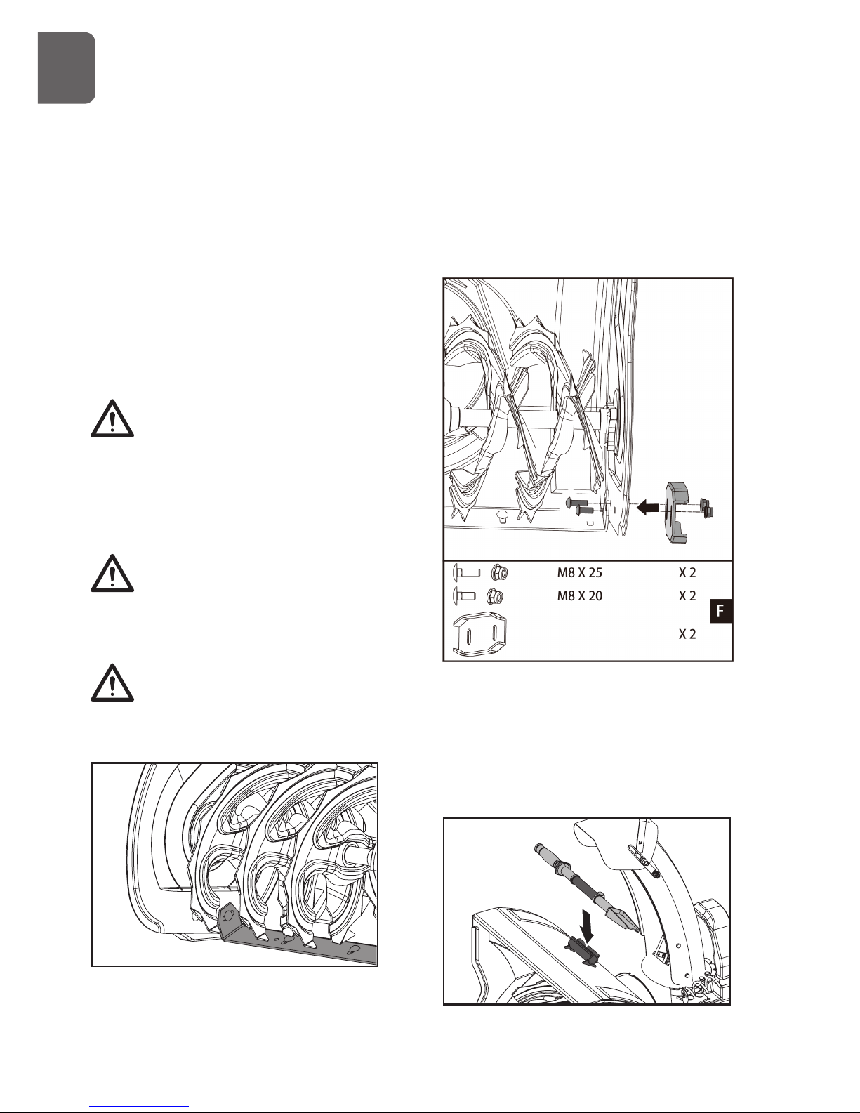
Chute Clean-Out Tool
G
B
Page 13
13
Fasten the clean-out tool to the mounting clip
on the rear of the auger housing.
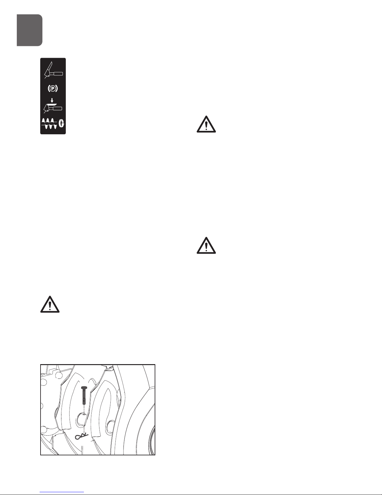
Replacement Shear Pins
A pair of replacement auger shear pins and
clevis pins are included with your snow thrower.
Store them in a safe place until needed.
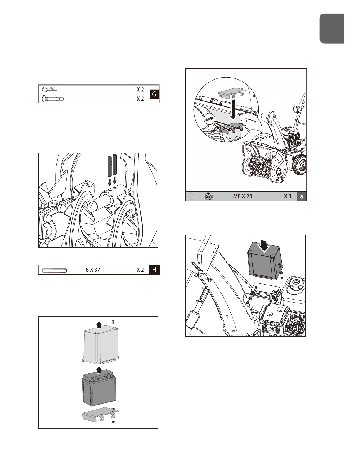
Spare Roll Pins
The impeller is secured to the impeller shaft
with roll pins.
Two 6x37 roll pins for impeller are supplied
as spare in the hardware bag. Store them in a
safe place until needed.
Battery (if so equipped)
1. Remove the battery cover by loosening
the screw and nut.
2. Take battery out of the tray.
3. Attach the tray to the auger housing with
screws and nuts.
4. Replace battery on the tray.
5. Connect positive (red) battery cable to
the battery terminal first, then negative
(black) battery cable. Check that all cable
connectors are tight.
6. Reinstall battery cover and tighten the
screw and nut.
G
B
Page 14
14
7. Operation
1
2
3
4
5
6
7
8
9
10
11
12
13
14
15
16
27
18
19
20
21
22
23
24
25
26
17
28 29
G
B
Page 15
15
1. Battery
2. Drift Cutters
3. Chute Clean-Out Tool
4. Shear Pins
5. Auger
6. Auger Gearcase
7. Scraper Blade
8. Drive Clutch Lever
9. Auger Clutch Lever
10. Headlight
11. Speed Shift Lever
12. Chute Crank
13. Chute Deflector Handle
14. Chute Deflector
15. Belt Cover
16. Discharge Chute
17. Skid Shoes
18. Fuel Filler Cap
19. Primer
20. Choke
21. Fuel Shutoff Valve
22. Recoil Starter
23. Electric Start Button
24. Power Cord Plug
25. Electric Starter
26. Engine Oil Fill Cap w/ Dipstick
27. Throttle Lever
28. Safety Ignition Switch
29. ON/OFF Switch
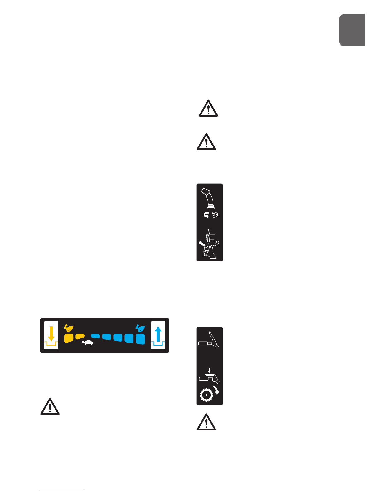
Speed Shift Lever
The speed shift lever has 8 positions: 6 forward
speeds and 2 reverse. To change speeds, move
the speed shift lever to the desired position.
The lever locks in a notch at each speed selection.
Always release the drive clutch lever
before changing speeds. Failure to
do so will result in damage to the
snow thrower.
Slower speeds are for heavier snow and faster
speeds are for light snow and transporting the
snow thrower. It is recommended that you use
a slower speed until you are familiar with the
operation of the snow thrower.
If the engine slows down under a
load or the wheels slip, shift the
machine into a lower gear.
If the front of the machine rides up,
shift the machine into a lower gear.
If the front continues to ride up, lift
up on the handles.
Discharge Chute Crank Lever
Rotate the discharge crank lever
clockwise to move the discharge
chute to the left; counterclockwise
to move the chute to the right.
Chute Deflector Handle
Move the deflector handle forward to move
the snow stream down; move it rearward to
move the snow stream up.
Drive Clutch Lever
Squeeze the clutch lever against
the handgrip to engage the wheel
drive. Release to disengage.
Always release the drive clutch lever
before changing speeds. Failure to
do so will result in damage to the
snow thrower.
G
B
Page 16
16
Auger Clutch Lever
Squeeze the clutch lever against
the handgrip to engage the auger
and start snow throwing action.
Release to disengage.
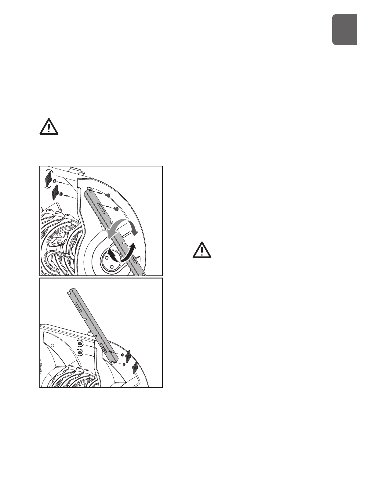
Scraper Blade & Skid Shoes
The scraper blade allows better contact with
the surface being cleared. It also prevents
damage to the housing from normal use.
The skid shoes are located on each side of
the auger housing and control the distance
between the scraper blade and the ground.
Adjust skid shoes equally to keep the scraper
blade level with the ground.
The scraper blade & skid shoes are subject
to wear and damage. Both scraper blade and
skid shoes are adjustable to compensate for
wear. They should be checked and adjusted
periodically. Replace when necessary.
Damage to auger housing will result
if scraper blade wears down too far.
Both scraper blade and skid shoes have two
wear edges. When one side wears out, they
can be rotated 180o to use the other edge.
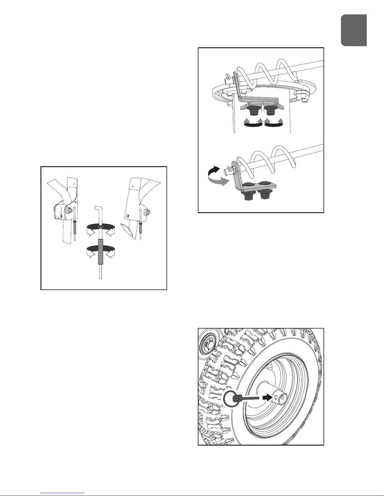
Shear Pins
The augers are secured to the auger shaft with
shear pins and clevis pins. If the auger should
strike a foreign object or ice jam, the snow
thrower is designed so that the pins may shear,
preventing damage to any other components. If
augers will not turn, check to see if the pins have
sheared. Replace the shear pins if necessary.
Do not substitute. Use only original
equipment shear pins as supplied
with your snow thrower.
Auger
When engaged, the augers rotate and draw
snow into the auger housing.
Discharge Chute
Snow drawn into the auger housing is
discharged out the discharge chute.
Chute Clean-Out Tool
Never use your hands to clear a
clogged discharge chute . Shut off
engine and remain behind handles
until all moving parts have stopped
before unclogging.
The chute clean-out tool is conveniently
fastened to the rear of the auger housing
with a mounting clip. Should snow and ice
become lodged in the discharge chute during
operation, proceed as follows to safely clean
the discharge chute and chute opening:
1. Release the auger clutch lever and shut off
the engine.
2. Remove the clean-out tool from the clip which
secures it to the rear of the auger housing.
3. Grasp the tool firmly by the handle and push and
twist the tool into the discharge chute to dislodge
the blockage.
4. Refasten the clean-out tool to the mounting
clip on the rear of the auger housing.
5. Make sure the discharge chute is pointed in a
safe direction (no vehicles, buildings, people, or
other objects are in the direction of discharge).
G
B
Page 17
17
Restart the engine. While standing in the operator’s
position (behind the snow thrower), engage the
auger control for a few seconds to clear any
remaining snow and ice from the auger housing
and the discharge chute.
Headlight (if so equipped)
The headlight provides added
safety in low-visibility conditions.
Turn the headlight switch to the
ON position to activate.
Drift Cutters (if so equipped)
Drift cutters break up snow drifts that are
taller than the auger housing and direct the
snow into the auger. Store the drift cutters on
the auger housing when not in use. Reposition
drift cutters so they face forward as shown.
Wing nuts should be fastened on the outside
of the auger housing.
Fuel Shutoff Valve
Always operate the snow thrower with the
fuel shut-off valve in the OPEN position. Close
the valve when you do not use the machine.
Throttle Lever
Move the throttle lever to the right to increase
the engine speed; move it to the left to
decrease the engine speed. Move the throttle
lever to the STOP position to stop the engine.
Choke
Engage choke by rotating lever to FULL
position whenever you are starting a cold
engine. As engine warms up, gradually rotate
the choke to the OFF position.
Do not use choke to start a warm engine.
Never use choke to stop engine.
Primer
Press the primer to pump additional fuel from
the carburetor to the cylinder for improved
cold weather starting.
Recoil Starter
The recoil starter is on the back side of the
engine. Pull the recoil starter handle to start
the engine.
Safety Ignition Switch (if so equipped)
Insert the safety ignition key for engine to
start and run. To stop the engine, remove the
key.
ON/OFF switch (if so equipped)
Used to stop the engine. Move switch to OFF
G
B
Page 18
18
position to stop engine. Place switch in ON
position for engine to start and run.
Ignition Switch (12V DC electric start)
The ignition switch is operated by a removable
key which has 3 positions of STOP, RUN and
START.
Electric Starter & Start Button (if so equipped)
The electric starter will start a properly choked
and cranked engine when the key is turned
(12V DC) or start button (120V or 230V AC) is
pushed.
To start the machine, connect the electric
starter to an electric power source with an
approved extension cord and press the start
button.
Thoroughly inspect the electrical cord
before using the machine. If the cord is
damaged, do not operate the machine.
Replace or repair the damaged cord immediately.
Connect extension cord to the electric
starter plug-in first and then to a power
outlet; disconnect the extension cord from
the power outlet first and then from the machine.
To prevent damaging the electric starter, do
not run it more than 5 continuous seconds
each time you try to start. Wait 10 seconds
between each attempt.
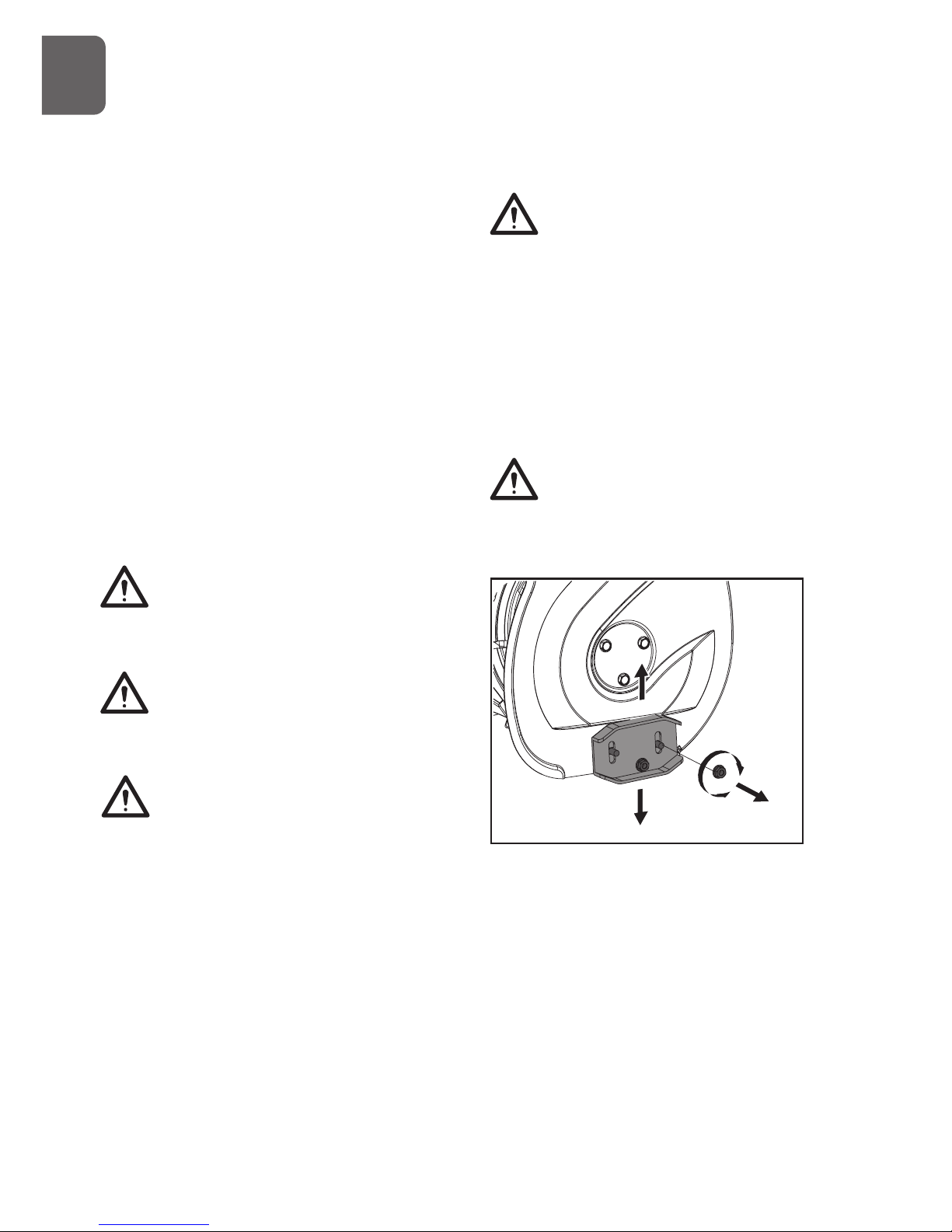
Adjustments
Skid Shoes
Position the skid shoes based on surface
conditions. For removal of snow in normal
conditions, such as a paved driveway or
sidewalk, place skid shoes in the higher
position to give a 3mm (1/8”) clearance
between the scraper blade and the ground.
Use a middle or lower position when the area
to be cleared is uneven, such as a gravel
driveway.
It is not recommended to operate the snow
thrower on gravel as it can easily pick up
and throw by the impeller, causing personal
injury or damage to the snow thrower and
surrounding property.
If you choose to operate the snow thrower
on a gravel surface, use extra caution and
keep the skid shoes in position for maximum
clearance between the ground and the scraper
blade.
Always adjust skid shoes after adjusting
scraper blade to prevent premature wear to
scraper blade or damage to auger housing.
To adjust the skid shoes:
1. Loosen the four hex nuts (two on each
side) and carriage bolts. Move skid shoes
to desired position.
2. Make sure the entire bottom surface of
skid shoe is against the ground to avoid
uneven wear on the skid shoes.
3. Retighten nuts and bolts securely.
Auger Clutch and Drive Clutch
When auger clutch lever or drive clutch lever
is released and in the disengaged position, the
G
B
Page 19
19
cable should have very little slack.
Auger must stop within 5 seconds when the
auger clutch lever is released. If auger clutch
does not engage or disengage properly, adjust
auger clutch before operation.
If the snow thrower’s drive is disengaging
intermittently during operation, or it drives
when you release the drive clutch lever, adjust
the drive clutch before operation.
Both auger clutch and drive clutch can be
adjusted as follows:
1. Loosen jam nut on adjustment turnbuckle.
2. Turn the adjustment turnbuckle up and down to
increase cable tension or provide more slack.
3. Retighten jam nut.
Chute Bracket
If the spiral at the bottom of the chute crank
lever is not fully engaging with the chute
assembly, the chute bracket can be adjusted.
To do so:
1. Loose the two nuts which secure the chute
bracket and reposition it slightly.
2. Retighten the nuts.
Freewheeling and Self-Propelling
To do so:
1. Loose the two nuts which secure the chute
bracket and reposition it slightly.
2. Retighten the nuts.
Freewheeling and Self-Propelling
Use the axle lock pin to lock or unlock the
right or left wheel. Lock both wheels to
increase traction; unlock one wheel to allow
for easier turning of the unit; unlock both
wheels for freewheeling.
G
B
Page 20
20
To unlock wheel, slide it inward and insert the
axle pin through the outer axle hole, but not
through the wheel hub.
To lock wheel, slide it outward and insert the
axle pin through the hole in the wheel hub and
the outer axle hole.
Starting and Stopping the Engine
Before starting the engine, check engine
oil level and ensure the engine is served as
described in the Engine Manual with the
snow blower.
Cold Start – Electric Starter (120V or 230 AC)
(if so equipped)
The engine is equipped with both A.C. electric
starter and a recoil starter. The electric starter
is equipped with a three-wire power cord and
plug and is designed to operate at the voltage
shown in the label.
Do not use the electric starter if
your household voltage different
from the one shown on the electric
starter.
1. Insert safety ignition key into ignition slot
until it clicks. Do not turn the key.
2. Be sure fuel shutoff valve is in the OPEN
position.
3. Move choke control to FULL position.
4. Push the primer 2 or 3 times. When temperature
is below -25oC (15oF), additional priming may
be needed. When temperature is above 10oC
(50oF), priming is not necessary.
Over priming may cause flooding,
preventing the engine from starting.
If you do flood the engine, wait a
few minutes before attempting to
start and do not push the primer.primer.
Some snow engine is not equipped
with primer as priming is not needed
for such engine.
5. Connect the extension cord to the engine.
6. Plug the other end of the extension cord
into a three-wire grounded receptacle.
7. Push starter button until engine starts.
To prevent damaging the electric starter, do
not run it more than 5 continuous seconds
each time you try to start. Wait 10 seconds
between each attempt.
8. When the engine starts, release the starter
button and slowly move the choke control
to the OFF position.
9. Disconnect the extension cord from the
receptacle first, then from the engine.
Cold Start – Electric Starter (12V DC) (if so
equipped)
1. Be sure fuel shutoff valve is in the OPEN
position.
2. Move choke control to FULL position.
3. Push the primer 2 or 3 times. When
temperature is below -25oC (15oF),
additional priming may be needed. When
temperature is above 10oC (50oF), priming
is not necessary.
Over priming may cause flooding,
preventing the engine from starting. If you
do flood the engine, wait a few minutes
G
B
Page 21

21
before attempting to start and do not push the
primer.
Some snow engine is not equipped
with primer as priming is not needed
for such engine.
4. Turn ignition key to the START position
until engine starts.
To prevent damaging the electric starter, do
not run it more than 5 continuous seconds
each time you try to start. Wait 10 seconds
between each attempt.
5. When the engine starts, release the ignition
key into RUN position and slowly move the
choke control to the OFF position.
Cold Start – Recoil Starter
1. Be sure fuel shutoff valve is in the OPEN
position.
2. Place ON / OFF switch in ON position.
3. Rotate choke control to FULL position.
4. Push the primer 2 or 3 times. When
temperature is below -25oC (15oF),
additional priming may be needed. When
temperature is above 10oC (50oF), priming
is not necessary.
Over priming may cause flooding,
preventing the engine from starting. If you
do flood the engine, wait a few minutes
before attempting to start and do not push the
primer.
5. Grasp recoil starter handle and pull rope out
slowly until it pulls harder. Let rope rewind slowly.
6. Pull rope with a rapid continuous full arm stroke.
Do not allow starter rope to snap back.
7. Repeat steps 5 and 6 until engine starts.
8. When the engine starts, release the recoil starter
handle and slowly move the choke control to the
OFF position.
Warm Start
Follow the steps above, keeping the choke
control in the OFF position and do not use
primer.
Allow the engine to warm up for a few
minutes, engine will not develop full power
until it has reached normal operating
temperature.
In snowy and cold conditions, some
controls and moving parts may freeze. Do
not use excessive force when trying to
operate frozen controls. If you have difficulty
operating any control or part, start the engine and
let is run for a few minutes.
Snow Throwing Tips
It is easier and more efficient to remove snow
immediately after it falls.
The best time to remove snow is the early
morning. At this time the snow is usually dry
and has not been exposed to the direct sun
and warming temperatures.
Slightly overlap each successive path to
ensure all snow will be removed.
For large areas, start in the middle and throw
snow to each side, so snow is not cleared
more than once.
For extremely heavy snow, reduce the width
of snow removal by overlapping previous path
and moving slowly.
Throw snow downwind whenever possible.
Keep engine clean and clear of snow during
use. This will help air flow and extend engine
life.
After snow-throwing is completed, let the
engine run for a few minutes to help dry
off the moisture on the engine and prevent
G
B
Page 22
22
moving parts from freezing. Engage the auger
to clear any remaining snow from inside
the housing. Rotate the discharge chute to
prevent it from freezing. Stop the engine, wait
for all moving parts to stop, and remove all
ice and snow from the snow thrower. With
the engine off, pull the recoil starter handle
several times to prevent the recoil starter from
freezing up.
8. Maintenance and Care
Engine
Refer to the Engine Operator’s Manual.
Lubrication
Auger Gearbox
The gearbox was filled with lubricant to the
proper level at the factory. Unless there is
evidence of leakage or service has been
performed on the gearbox, no additional
lubricant should be required. If lubricant is
required, use GL-5 or GL-6, SAE85-95, EP
gear oil lubricant. Do not use synthetic oil.
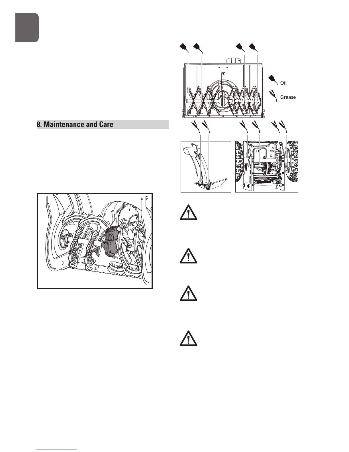
General Lubrication
Lightly lubricate all moving parts of the
machine at the end of the season or every 25
operating hours.
Do not allow grease or oil get on friction
disc, friction plate or belts. Do not
excessively oil the machine; extra oil may
enter the traction drive and cause the traction
drive belt to slip.
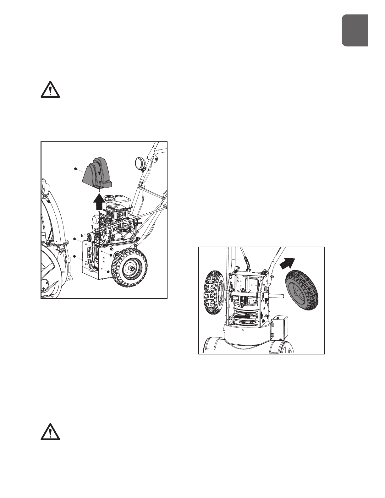
When lubricating auger shaft, remove shear
pins to apply oil inside the shaft and around
spacers and flange bearings found at either end
of the shaft.
Remove the wheels to apply grease
the wheel shaft.
Battery (if so equipped)
Battery is maintenance-free. Do not tamper
with or attempt to open battery.
Keep battery and its terminals clean.
1. Remove battery cover.
2. Detach the negative (black) battery cable from
the battery first to prevent a short circuit, then the
positive (red) battery cable.
3. Take the battery out of the tray.
G
B
Page 23
23
4. Remove corrosion from battery terminals and
cable connections with a wire brush, then wash
with weak baking soda solution.
5. Apply a thin coat of grease or petroleum jelly to
terminals and cable ends to retard corrosion.
6. Attach and tighten the positive (red) battery cab
first, then the negative (black) battery cable.
7. Place the battery on the tray and Install the
cover.
Off-Season Storage
Refer to the Engine Manual for
information on storing your engine.
At the end of the season or if the snow
thrower will not be used for 30 days longer,
follow the storage instructions below.
1. Run the engine until the fuel lines and
carburetor are empty and it stops due to
lack of fuel.
2. Remove the safety ignition key and allow
the engine to cool.
3. Lubricate the machine as instructed.
4. Clean the exterior of the engine and the
snow thrower thoroughly.
5. Touch up all rusted or chipped paint
surfaces; sand affected areas before
painting, and use a rust preventative to
prevent the metal parts from rusting.
6. Tighten all loose screws, bolts, and
locknuts. Repair or replace any damaged
parts.
7. Cover the machine and store it in a clean,
dry place out of the reach of children.
Belt Replacement
Auger Belt
If the auger belt becomes worn, oil-soaked,
or otherwise damaged, proceed as follows to
replace the belt.
1. To prevent spillage, remove all fuel from
tank by running engine until it stops.
Remove the key to avoid unintended
starting and allow unit to cool completely.
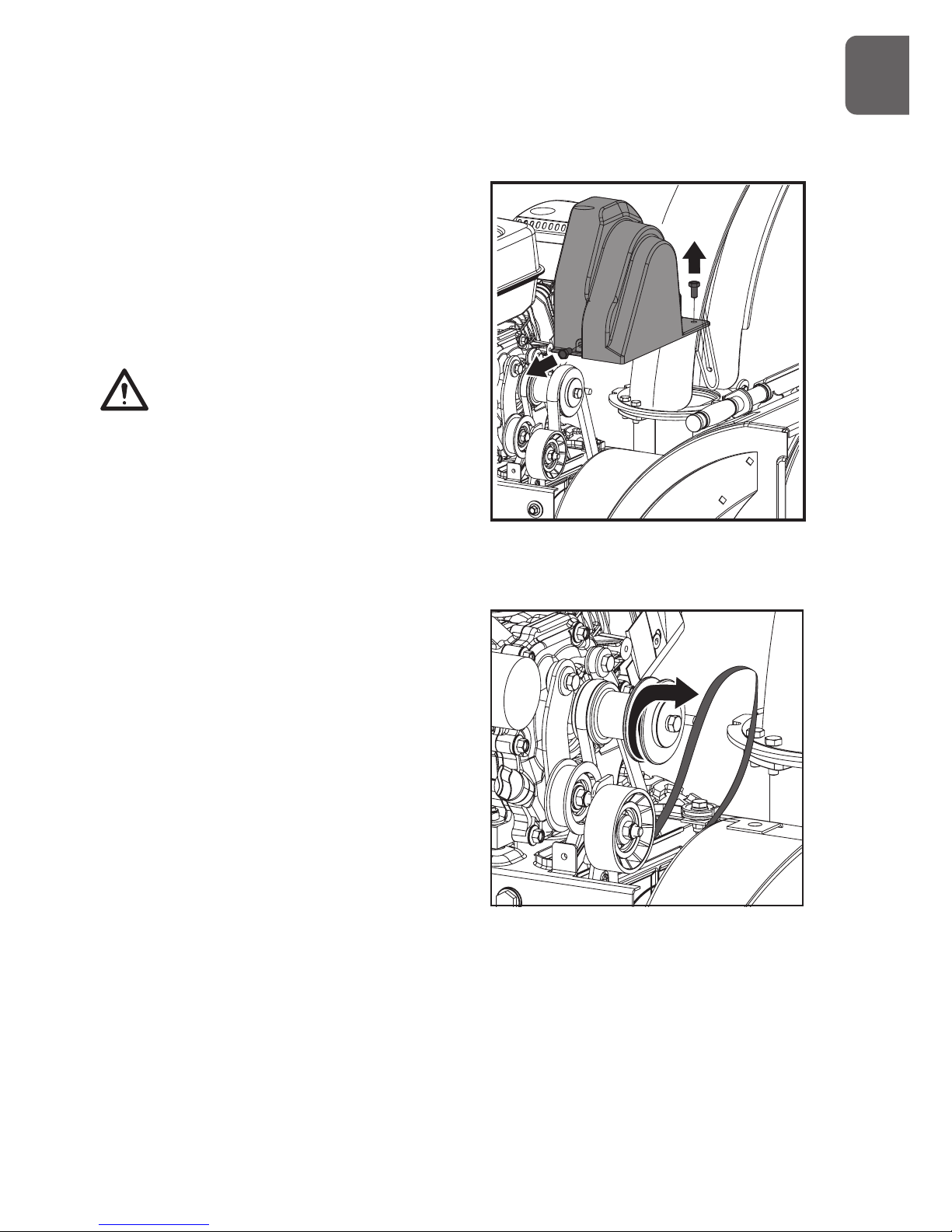
2. Remove the two screws that hold the belt
cover in place and set the cover aside.
3. Roll the auger belt(s) off the engine pulley.
4. Carefully pivot the snow thrower up and
forward so that it rests on the auger housing.
G
B
Page 24
24
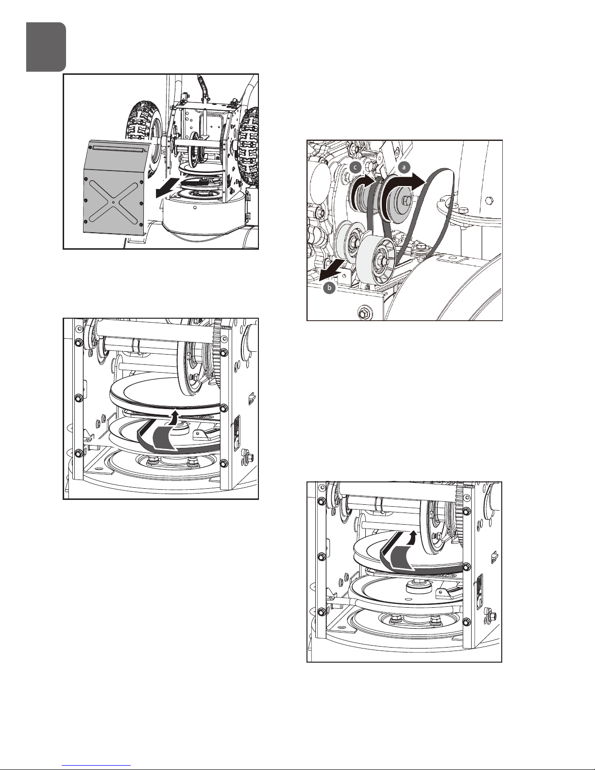
5. Remove the frame cover from the underside
of the snow thrower by removing the screws
which secure the cover.
6. Remove the belt(s) from around the auger
pulley, and slip the belt(s) between the
support bracket and the auger pulley.
7. Replace the auger belt(s) by following
instructions in reverse order.
Drive Belt
If the drive belt becomes worn, oil-soaked, or
otherwise damaged, proceed as follows to
replace the belt.
1. To prevent spillage, remove all fuel from
tank by running engine until it stops.
Remove the key to avoid unintended
starting and allow unit to cool completely.
2. Remove the two screws that hold the belt
cover in place and set the cover aside.
3. Remove the belt as follows.
a. Roll the auger belt off the engine pulley.
b. Pivot the idler pulley toward the right
to relieve tension.
c. Lift the drive belt off engine pulley.
4. Carefully pivot the snow thrower up and
forward so that it rests on the auger housing.
5. Remove the frame cover from the underside
of the snow thrower by removing the screws
which secure the cover.
G
B
Page 25
25
8. Place belt(s) onto engine sheave(s).
9. Reinstall the chute crank lever.
Friction Wheel Replacement
If the snow thrower fails to drive with the drive
clutch engaged, and performing the clutch
control cable adjustment fails to correct the
problem, the friction wheel may need to be
replaced.
1. To prevent spillage, remove all fuel from
tank by running engine until it stops.
Remove the key to avoid unintended
starting and allow unit to cool completely.
2. Carefully pivot the snow thrower up and
forward so that it rests on the auger housing.
3. Remove the frame cover(s) from the
underside of the snow thrower by
removing the screws which secure the
cover(s).
4. Remove the right-hand wheel by removing
the axle lock pin.
6. Slip the drive belt off the pulley and between
friction wheel and friction wheel disc.
7. Remove and replace belt in the reverse order.
Holding down the drive clutch lever
will ease reinstallation of the belt.
If an assistant is available, you can also
separate the auger housing from the frame
assembly to replace belts.
1. Shut off engine, remove key, disconnect spark
plug wire and allow unit to cool completely.
2. Remove belt cover.
3. Remove the clevis pin and washer from the chute
crank lever to remove it from the lower branket.
4. Remove bottom cover to avoid bending it
when tipping unit apart.
5. Remove the screws securing auger housing to
the frame (two on each side).
Tip auger housing and frame apart.
6. Replace auger belt or drive belt.
7. Tip auger housing and frame back together
and secure with screws.
Holding down the auger clutch lever
will ease reconnection of the auger
housing and frame.
G
B
Page 26
26
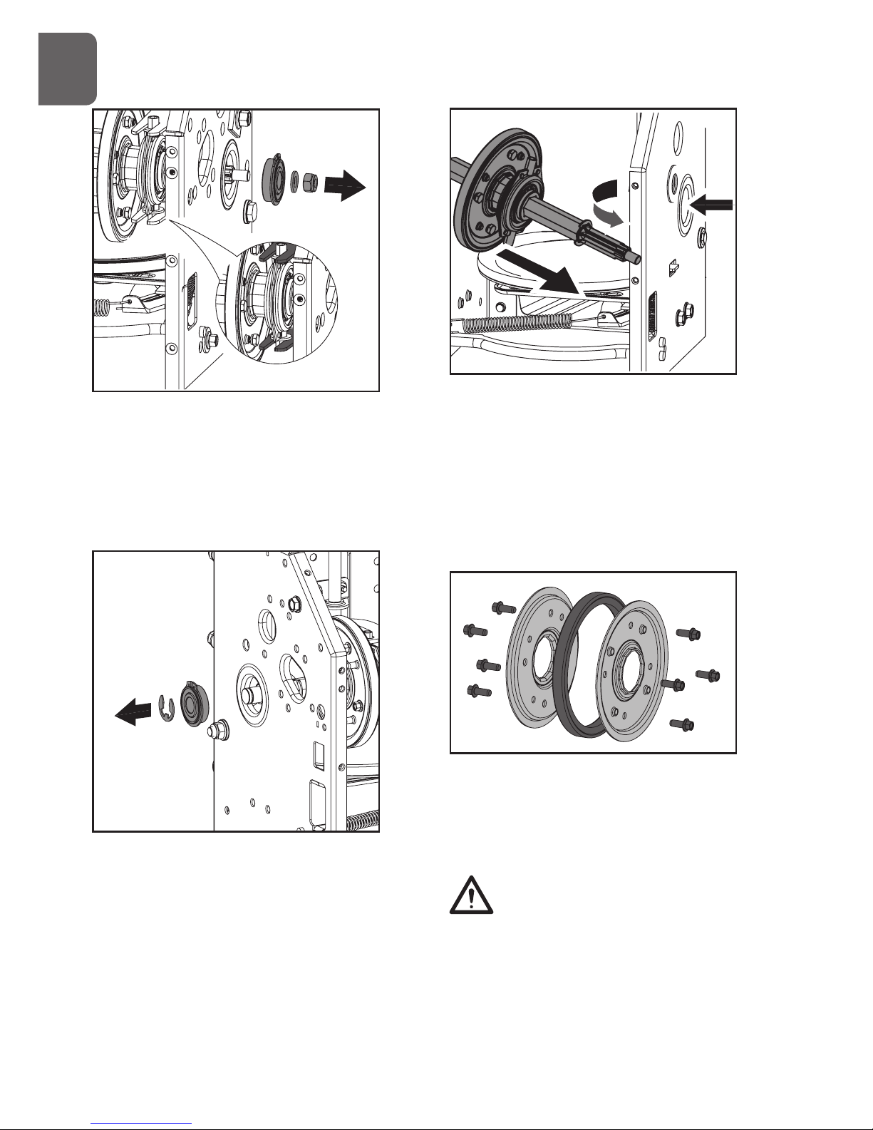
5. Carefully remove the hex nut which
secures the hex shaft to the snow thrower
frame and lightly tap the shaft’s end to
dislodge the ball bearing from the right
side of the frame. Be careful not to damage
the threads on the shaft.
6. Remove the other bearing from the left side
of the frame by removing the snap ring.
7. Carefully position the hex shaft downward
and to the left before carefully sliding the
friction wheel assembly off the shaft.
8. Follow the previous steps in reverse order
to reassemble.
If you only want to replace the rubber ring,
proceed as follows:
1. Remove the eight screws which secure the
friction wheel’s side plates together.
2. Remove the rubber ring from between the plates.
3. Reassemble the side plates with a new rubber
ring.
When reassembling the friction wheel
assembly, make sure that rubber ring is
centered and seated properly between the
side plates. Tighten each screw only one rotation
before turning the wheel clockwise and
proceeding with the next screw on the other side
of the wheel. Repeat this process several times to
G
B
Page 27
27
Secure unit chassis to transport vehicle. Never
secure from rods or linkages that could be
damaged.
10. ENVIRONMENTAL
Recycle unwanted materials instead
of disposing of them as waste. All
tools, hoses and packaging should
be resorted, taken to the local
recycling center and disposed off in
an environment-friendly safe way.
ensure the plates are secured with equal force
between 90N.m(6 ft-lbs) and 130N.m(9 ft-lbs).
4. Slide the friction wheel assembly back
onto the hex shaft. Make sure the shift
lever pin is in place in the bearing housing.
Follow the steps above in reverse order to
reassemble components.
Charging Battery (if so equipped
Follow the instructions below to charge
battery:
1. Remove battery cover.
2. Disconnect negative (black) battery cable
first, then positive (red) battery cable.
3. Take battery out of the tray and place it on
bench or other well-ventilated place.
4. Connect positive (+) lead of charger to
positive (+) terminal, and negative (-) lead
to negative (-) terminal.
5. Charge the battery at two and a half amps
for ten hours.
6. Reinstall battery into unit.
9 . Transport
To travel from one work area to another:
1. Set throttle to slow or part-throttle position.
2. On wheeled model, press down on handle bars
enough to raise front of unit slightly off surface; on
tracked model, move the track lock lever into the
transport position.
3. Engage drive clutch without engaging auger
clutch.
Always shut off engine, remove key, and
close fuel shut-off valve when transporting
unit on a truck or trailer. Do not transport
machine while engine is running.
Use extra care when loading or unloading unit
onto trailer or truck.
G
B
Page 28

28
11. TROUBLE SHOOTING
Problem Cause Remedy
Electric starter does
not turn(on models so
equipped)
1. Extension cord not connected.
2. The extension cord is worn,
corroded, or damaged.
3.The power outlet is not energized.
1. Connect the extension cord to
the outlet and/or the machine.
2.Replace the extension cord.
3. Have a qualified electrician
energize the outlet.
Engine fails to start 1. Choke not in CHOKE position.
2.Engine not primed.
3.Engine is flooded.
4.Fuel shut-off valve closed.
5. Throttle in STOP position or ON/
OFF switch is OFF.
6. Spark plug wire loose or
disconnected.
7.Fuel tank empty or stale fuel.
8.Faulty spark plug.
9.Safety ignition key is not inserted.
10. The engine oil level in the engine
crankcase is too low or too high
1. Move choke to CHOKE position.
2. Prime engine as instructed in
this manual.
3. Wait a few minutes before
restarting, do not prime.
4.Open fuel shut-off valve.
5. Move throttle to FAST position
or ON/OFF switch to ON Position.
6. Connect or tighten spark plug
wire.
7. Fill tank with clean, fresh
gasoline.
8. Clean, adjust gap, or replace.
9. Insert safety ignition key.
10. Add or drain oil to adjust the oil
level in the engine crankcase.
Engine idles or runs
roughly
1. Engine running on CHOKE.
2. Fuel tank is nearly empty or stale
fuel.
3.Contaminated fuel supply.
4.Carburetor out of adjustment.
5.Engine over-governed.
6. The fuel shutoff valve is not
completely open or blockage in
fuel line.
7.Spark plug wire loose.
8.Faulty spark plug.
9. The engine oil level in the engine
crankcase is too low or too high.
1. Move choke lever to RUN
position.
2. Fill tank with clean, fresh
gasoline.
3. Replace with clean fuel.
4 . Contact a qualified repair
personnel.
5. Contact a qualified repair
personnel.
6. Open the fuel shutoff valve or
clean fuel line.
7. Tighten spark plug wire.
8. Clean, adjust gap, or replace.
9. Add or drain oil to adjust the oil
level in the engine crankcase.
The engine overheats Carburetor not adjusted properly. Contact a qualified repair
personnel.
Excessive vibration Loose parts or damaged parts. Tighten all fasteners or replace
damaged parts.
G
B
Page 29

29
Loss of power 1. Spark plug wire loose.
2. Gas gap vent hole plugged.
3. Dirty or clogged muffler.
1. Tighten spark plug wire.
2. Clean or replace fuel cap.
3. Clean or replace muffler.
Loss of traction drive 1. Drive control cable not adjusted
properly.
2. Drive belt loose or damaged.
3. Friction wheel worn.
1. Adjust drive control cable.
2. Replace drive belt.
3. Replace friction wheel.
Loss of snow discharge or
slowing of snow discharge
1. Discharge chute clogged.
2. Augers or impeller jammed.
3. Auger control cable not adjusted
properly.
4. Auger belt loose or damaged.
5.Shear pin(s) sheared.
6. Throttle not in FAST position
when throwing snow.
7. Moving too fast to clear the snow.
8. Throwing too much snow.
9. Trying to remove extremely heavy
or wet snow.
10. Auger is frozen in place.
1. Unclog discharge chute.
2. Remove debris or foreign object
from augers or impeller.
3. Adjust auger control cable.
4. Replace auger belt.
5. Replace with new shear pin(s).
6. Move throttle to FAST position.
7. Shift into a lower gear.
8. Reduce speed and width of
swath.
9. Do not overload with extremely
heavy or wet snow.
10. Move unit to a warm place to
thaw.
Discharge chute either
does not lock into place or
does not move
1. The discharge chute control not
adjusted properly.
2. Chute assembly incorrectly
1. Adjust the discharge chute
control.
2. Disassemble chute control and
reassemble as instructed in this
manual.
Machine does not properly
clear the snow of the surface
1. The skid shoes and/or scraper
blade not adjusted properly.
2. The pressure in the tires not equal.
1. Adjust the skid shoes and/or the
scraper blade.
2. Check and adjust the pressure
in one or both tires.
G
B
Page 30
30
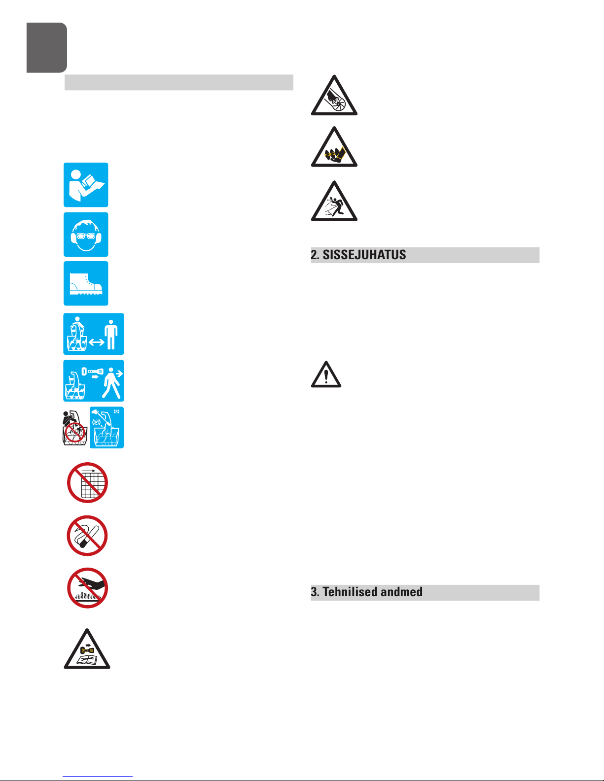
1. SÜMBOLID
Seadme andmesildil võidakse kasutada sümboleid.
Need näitavad olulist infot toote või selle
kasutamise kohta.
Need juhised tuleb tähelepanelikult läbi
lugeda.
Kanda tuleb kaitseprille.
Kasutada kuulmekaitsevahendeid.
Jalga tuleb panna kaitsejalatsid.
Läheduses ei tohi viibida kõrvalisi
isikuid.
Kasutaja peab enne seadme juurest
lahkumist seiskama mootori ja
eemaldama süütevõtme.
Ummistuse kõrvaldamiseks tuleb
alati kasutada puhastustööriista.
Seda ei tohi kunagi teha käega.
Keelatud on eemaldada kaitse- ja
ohutusseadiseid või muuta nende
konstruktsiooni.
Seadme lähedal ei tohi suitsetada ega
kasutada lahtist tuld.
Kuuma summutit, reduktori korpust või
silindrit ei tohi puudutada.
Enne seadme remontimist või
reguleerimist tuleb alati seisata mootor
ja eemaldada süütevõti. Vt juhendit.
E
E
Seadme töötamise ajal tuleb jälgida, et
kätt ei panda sissevõtu- ja väljutuskoha
juurde.
Hoida pöörlevast tigumehhanismist
eemale.
Lund ei tohi kunagi väljutada inimeste
või asjade suunas.
2. SISSEJUHATUS
See lumepuhur ületab kõik teie ootused. Selle
seadme tootmisel on parimate tööomaduste
tagamiseks järgitud rangeid kvaliteedistandardeid.
Seda on lihtne ja ohutu kasutada ning õige
hooldamise korral töötab see veel palju aastaid.
Enne lumepuhuri kasutuselevõtmist tuleb
kogu kasutusjuhend tähelepanelikult läbi
lugeda. Eriti tuleb tähelepanu pöörata
ettevaatusmeetmetele ja hoiatustele.
Lumepuhuril on palju omadusi, mis teevad selle
kasutamise kiiremaks ja kergemaks. Selle seadme
väljatöötamisel seati eesmärgiks ohutus, jõudlus ja
töökindlus, nii et hooldamine ja kasutamine on
lihtne.
Mootori tootja vastutab kõige eest, mis on seotud
mootoriga: jõudlus, nimivõimsus, tehnilised
andmed, garantii ja hooldus. Lisateave on esitatud
mootori tootja koostatud kasutusjuhendis, mis on
eraldi pakendis seadmega kaasas.
3. Tehnilised andmed
SPT-182-570:
Mootori tüüp: OHV, neljataktiline mootor,
õhkjahutuse; 182 cc
Mootori võimsus: 4,0 kW
Maksimaalne võimsus: 4,5kW, 6 HP
Käivitussüsteem: 230V elektri start (valikuline)
Page 31

31
Kütusepaagi maht: 3.0L
Puhastuslaius 57 cm
Sissevõtu kõrgus 53,5 cm
Teo läbimõõt 30,0 cm
Rootori läbimõõt 30,0 cm
Käik 6 edasi + 2 tagasi
SPT-270-720:
Mootori tüüp: OHV, neljataktiline mootor,
õhkjahutuse; 182 cc
Mootori võimsus: 5,3 kW
Maksimaalne võimsus: 6,7kW, 9 HP
Käivitussüsteem: 230V elektri start (valikuline)
Kütusepaagi maht: 6.0L
Puhastuslaius 72 cm
Sissevõtu kõrgus 53,5 cm
Teo läbimõõt 30,0 cm
Rootori läbimõõt 30,0 cm
Käik 6 edasi + 2 tagasi
SPT-302-720:
Mootori tüüp: OHV, neljataktiline mootor,
õhkjahutuse; 302cc
Mootori võimsus: 6,2 kW
Maksimaalne võimsus: 7,5kW, 10 HP
Käivitussüsteem: 230V elektri start (valikuline)
Kütusepaagi maht: 4.0L
Puhastuslaius 72 cm
Sissevõtu kõrgus 53,5 cm
Teo läbimõõt 30,0 cm
Rootori läbimõõt 30,0 cm
Käik 6 edasi + 2 tagasi
4. OHUTUS
Üldised ohutusnõuded
Seadme tundmaõppimine
Seadmega on lubatud töötada ainult täiskasvanutel,
kes seda tunnevad. Kunagi ei tohi seda seadet
kasutada lapsed.
Kasutusjuhend ja seadmel paiknevad sildid tuleb
läbi lugeda, nii et neist on aru saadud. Tundma
tuleb õppida nii seadme kasutamist ja piiranguid
kui ka võimalikke ohte.
Põhjalikult tuleb tutvuda juhtseadiste ja nende õige
kasutamisega. Õppida selgeks, kuidas saab
seadme peatada ja juhtseadised kiiresti vabastada.
Seadme komplekti kuuluvast mootori tootja
kasutusjuhendist tuleb kindlasti läbi lugeda kõik
juhiseid ja ohutusnõuded. Seadet ei tohi kasutama
hakata enne, kui olete täielikult aru saanud sellest,
kuidas mootor õigesti tööle rakendada ja kuidas
seda hooldada. Samuti tuleb teada, kuidas vältida
kehavigastusi ja/ või varalist kahju.
Tööpiirkond
Mootorit ei tohi kunagi käivitada ega lasta sellel
töötada kinnises ruumis. Heitgaas on ohtlik,
sisaldades vingugaasi, mis on lõhnatu ja eluohtlikult
mürgine gaas. Seda seadet tohib kasutada ainult
hea õhuvahetusega välistingimustes.
Seadmega ei tohi kunagi töötada halva nähtavuse
korral või pimedas.
Seadet ei tohi kunagi kasutada järsul kallakul.
Kasutaja ohutus
Seadmega ei tohi töötada narkootiliste ainete,
alkoholi
või mistahes ravimi mõju all olles, mis võib
mõjutada kasutaja võimet seadet õigesti kasutada.
Kanda tuleb asjakohast riietust. Kasutada tuleb
tugevaid pikki pükse, saapaid ja kindaid. Rõivad ei
tohi olla liiga avarad, kanda ei tohi lühikesi pükse
ega mingeid ehteid. Pikad juuksed tuleb kinni
panna, et need oleksid õlgadest kõrgemal. Hoida
juuksed, rõivad ja kindad liikuvatest osadest eemal.
Liiga avarad rõivad, ehted ja pikad juuksed võivad
takerduda seadme liikuvate osade vahele.
Kasutada tuleb kaitsevarustust. Töötades
tuleb alati kanda kaitseprille. Asjakohane
kaitsevarustus (nt tolmurespiraator, kaitsekiiver
või kuulmekaitsevahendid) aitab vähendada
tervisekahjustuste ohtu.
E
E
Page 32

32
Enne töölerakendamist tuleb seade üle kontrollida.
Kaitsekatted peavad olema oma kohale paigaldatud
ja töökorras. Kontrollida, et kõik mutrid, poldid jms
on tugevalt kinni. Enne mootori käivitamist tuleb
vabastada kõik sidurid ja seada käiguvahetushoob
neutraalasendisse.
Seadet ei tohi kunagi kasutada, kui see vajab
remonti või on tehniliselt halvas seisukorras.
Kahjustunud, puuduvad või rikkis osad tuleb enne
seadme kasutamist uutega asendada. Kontrollida,
et ei esine kütuseleket. Jälgida, et seade on alati
töökorras ja ohutu.
Kunagi ei tohi omavoliliselt muuta ohutusseadiseid.
Regulaarselt tuleb kontrollida, et need
funktsioneerivad õigesti.
Seadet ei tohi kasutada, kui mootori seguklapi
hoova abil ei saa seda sisse ja välja lülitada.
Bensiinimootoriga seade on alati ohtlik, kui seda
ei saa seguklapi hoova abil lülitada. Sel juhul tuleb
seguklapi hoob enne seadme kasutamist välja
vahetada.
Harjumuseks peab saama, et enne
käivitamist kontrollitakse, kas mutrivõtmed
ja reguleerimistööriistad on seadme juurest
eemaldatud. Seadme pöörleva osa külge jäetud
tööriist või mutrivõti võib põhjustada kehavigastuse.
Seadmega töötades tuleb olla tähelepanelik, jälgida
oma tegevust ja kasutada tervet mõistust.
Liiga palju ei tohi ette kummarduda. Seadmega ei
tohi töötada paljajalu ega kandes sandaale vms
kergeid jalatseid. Kanda tuleb turvajalatseid, mis
kaitsevad jalgu ja pakuvad libedatel pindadel
kindlamat jalgealust. Alati tuleb seista kindlal
pinnal ja töötada stabiilses asendis. See võimaldab
seadet ootamatus olukorras paremini kontrollida.
Vältida tuleb tahtmatut käivitumist. Enne seadme
transportimist, reguleerimist või hooldustööde
tegemist tuleb alati üle kontrollida, et seguklapi
hoob on väljalülitatud asendis. See, kui seguklapi
hoob on transportimise, reguleerimise või
hooldustööde ajal sisselülitatud asendis, võib
põhjustada õnnetusjuhtumi.
Kütuse ohutu käitlemine
Kütus on väga tuleohtlik ja selle aur võib süttimisel
plahvatada. Raskete kehavigastuste
ohu vähendamiseks tuleb rakendada
ettevaatusmeetmeid.
Kütusepaaki on lubatud täita või tühjendada ainult
välistingimustes, puhtas ja hea õhuvahetusega
kohas, kasutades nõuetekohast kütusekanistrit.
Selle koha lähedal, kus kütust lisatakse või
seadet kasutatakse, ei tohi suitsetada ega
tekitada sädemeid, kasutada lahtist tuld või muid
süütamisohtlikke asju.
Kunagi ei tohi kütust lisada sisetingimustes.
Sädemete või elektrikaare vältimiseks tuleb
maandatud pingealtid esemed (näiteks tööriistad)
hoida eemal pingestatud elektriahelatest ja
ühendustest, mis on katmata. Muidu tekib heitgaasi
või bensiiniauru süttimise oht.
Enne kütusepaagi täitmist tuleb mootor alati seisata
ja lasta sellel jahtuda. Siis, kui mootor töötab või on
töötamisest veel soe, ei tohi eemaldada ütusepaagi
korki ega lisada paaki kütust. Seadet ei tohi
kasutada, kui kütusesüsteemis on leke.
Kui see on võimalik, tuleb seade kütuse lisamiseks
veokilt või haagiselt maapinnale tõsta. Kui see ei
ole võimalik, tuleb haagisel olevasse seadmesse
kütust lisada teisaldatavast kanistrist, mitte tankuri
püstolist.
Kütusepaagi kork tuleb lahti keerata aeglaselt, et
kütusepaak jõuaks rõhu alt vabaneda.
Tankuri püstolit tuleb kuni täitmise lõpetamiseni
hoida pidevalt kokkupuutes kütusepaagi või kanistri
ava servaga. Kasutada ei ole lubatud fikseeritava
avamisseadisega püstolit.
Kunagi ei tohi kütusepaaki panna liiga täis. Paaki ei
tohi lisada rohkem kütust kui kuni 12,5 mm (1/2“)
E
E
Page 33

33
allpool täiteava, et jätta ruumi kütuse paisumiseks
mootori ja/või päikese soojuse mõjul.
Seejärel tuleb kütusepaagi ja kanistri kork taas
kindlalt kinni keerata ning pühkida mahaloksunud
kütus ära. Seadet ei tohi kasutada, kui kütusepaagi
kork ei ole kindlalt kinni.
Vältida tuleb süütamisohtlike asjade sattumist mahaloksunud kütuse lähedale. Kui kütust on maha
loksunud, siis ei tohi mootorit käivitada, vaid seade
tuleb kütuseloigust eemale viia ja vältida igasugust
süttimisohtu, kuni kütuseaur on hajunud. Nahale või
riietele loksunud kütus võib süttida ja põhjustada
raskeid kehavigastusi. Nahk tuleb kohe puhtaks
pesta ja riided vahetada.
Kütust tuleb hoida spetsiaalsetes kanistrites, mis
on selleks otstarbeks lubatud.
Kanistreid ei tohi kunagi täita sõiduki sees ega
veoki või haagise plastkattega kastis. Kanistrid
tuleb enne täitmist alati paigutada sõidukist eemal
maapinnale.
Kütust tuleb hoida jahedas, hea õhuvahetusega
kohas, ohutult eemal sädemetest, lahtisest tulest
või muudest süütamisohtlikest asjadest.
Kütust või seadet, mille paagis on kütust, ei tohi
kunagi hoida hoones, kus kütuseaur võib kokku
puutuda sädemete, lahtise tule või süütamisohtlike
asjadega (boiler, küttekolle, pesukuivati jms). Enne
seadme hoiulepanekut kinnisesse ruumi tuleb
mootoril alati lasta jahtuda.
Seadme kasutamine ja hooldamine
Seadet ei tohi kunagi üles tõsta ega kanda, kui
selle mootor töötab.
Seadet ei tohi üle koormata. Kasutada tuleb
konkreetseks tööks sobivat seadet. Seade töötab
kõige paremini ja ohutumalt, kui seda kasutatakse
ettenähtud koormusel.
Mootori pöörlemissageduse regulaatori seadistust
ei tohi muuta, samuti ei tohi mootorit käitada liiga
suurel kiirusel. Mootori pöörlemissageduse
regulaator tagab mootori maksimaalse ohutu
töökiiruse.
Käsi ja jalgu ei tohi panna seadme pöörlevate
osade lähedale.
Vältida tuleb kokkupuutumist kuuma kütuse, õli,
heitgaasi ja kuumade pindadega. Mootorit ja
summutit ei tohi puudutada. Need osad lähevad
töötamise ajal väga kuumaks ja on mõnda aega
kuumad ka pärast seadme väljalülitamist. Enne
hooldustööde tegemist või reguleerimist tuleb
mootoril lasta jahtuda.
Kui põrgatakse millegi vastu, siis tuleb mootor
seisata, võtta juhe süüteküünla küljest lahti ja
kontrollida põhjalikult üle, et seade ei ole saanud
kahjustada. Enne taaskäivitamist ja tööleasumist
tuleb kahjustused ära parandada.
Kui seade hakkab tegema ebaharilikku müra
või vibreerima, tuleb mootor kohe välja lülitada,
ühendada süüteküünla juhe lahti ja selgitada välja
müra või vibratsiooni põhjus. Ebatavaline müra või
vibratsioon annab tavaliselt märku rikkest.
Kasutada võib ainult neid lisaseadiseid ja tarvikuid,
mida tootja on lubanud. Selle nõude eiramine võib
põhjustada kehavigastusi.
Seade tuleb hoida töökorras. Kontrollida, et liikuvad
osad on õiges asendis ja saavad vabalt liikuda.
Samuti tuleb kontrollida, et osad ei ole purunenud,
ning jälgida kõike muud, mis võib mõjutada seadme
tööd. Seadet võib kasutada alles siis, kui
kahjustused on parandatud. Paljud õnnetused
juhtuvad halvasti hooldatud seadme tõttu.
Mootor ja summuti tuleb tuleohu vähendamiseks
hoida puhas rohust, lehtedest, liigsest määrdest ja
tahmast.
Seadme peale ei tohi kunagi pritsida ega valada
vett ega muud vedelikku. Käepidemed tuleb hoida
kuivad, puhtad ja prahist vabad. Pärast iga
kasutuskorda tuleb seade puhastada.
E
E
Page 34

34
Keskkonna kaitsmiseks tuleb jälgida bensiini, õli
jms jäätmekäitluse kohta kehtivaid õigusnorme.
Kui seadet ei kasutata, tuleb seda hoida sellises
kohas, kus lapsed seda kätte ei saa. Seadet ei tohi
lubada kasutada isikutel, kes seda ei tunne ega ole
tutvunud selle kasutusjuhendiga. Väljaõppeta
kasutaja käes on seade ohtlik.
Hooldus
Enne seadme puhastamist, remontimist,
ülevaatamist või reguleerimist tuleb mootor välja
lülitada ja kontrollida, et kõik liikuvad osad on
seiskunud. Alati tuleb üle kontrollida, et mootori
seguklapi hoob on asendis STOP. Ühendada
süüteküünla juhe lahti ning hoida juhe juhusliku
käivitumise vältimiseks süüteküünlast eemal.
Seadet võib lasta hooldada ainult asjakohase
kvalifikatsiooniga tehnikul, kes kasutab identseid
varuosi. Nii on seadme ohutus tagatud.
Seadmekohased ohutusnõuded
Seadmega ei tohi töötada isik, kes ei kanna
sobivaid talverõivaid.
Seadet ei ole lubatud kasutada katusel.
Mootoril ei tohi lasta töötada siseruumis, välja
arvatud mootori käivitamise ajal ja lumepuhurit
hoonesse või välja teisaldades. Sel juhul tuleb
avada välisuksed, sest heitgaas on ohtlik.
Enne seadme kasutamist tuleb alati tähelepanelikult
kontrollida, et üleval ja külgedel jääb piisavalt vaba
ruumi. Tänavatel või teepeenardel töötades tuleb
alati jälgida liiklust.
Tööpiirkond tuleb põhjalikult üle vaadata.
Tööpiirkond tuleb hoida puhas, seal ei tohi olla
mänguasju, uksematte, ajalehti, kelke, lumelaudu,
juhtmeid ega mingeid muid esemeid, millele
lumepuhur võib otsa sõita või mille võib teo/
rootoriga eemale paisata. Kontrollida tuleb nõrku
kohti sildadel, kaldteedel ja põrandatel.
Lumekoristuse marsruut tuleb plaanida nii, et
välditakse lume heitmist inimeste poole või
kohtadesse, kus võib tekkida varakahju.
Töötada ei tohi järsakute, kraavide või
kaldapealsete läheduses. Kui ratas liigub üle
järsaku või kraavi serva või serv variseb, võib
seade ootamatult ümber minna.
Kõik kõrvalised isikud, lapsed ja loomad tuleb hoida
vähemalt 23 m kaugusel. Kui keegi läheneb, tuleb
seade kohe seisata.
Elektrilise käivitiga mootori korral tuleb alati
kasutada kolmesoonelist maandatud pikendusjuhet
ja pistikupesa.
Regulaarselt tuleb kontrollida, et sidur ja pidur on
töökorras. Vajaduse korral tuleb neid reguleerida ja
hooldada. Veorataste ja teo/rootori liikumine peab
kiiresti lõppema, kui juhthoovad vabastatakse.
Enne lumekoristuse alustamist tuleb mootoril ja
seadmel lasta kohanduda välistemperatuuriga.
Tähelepanelik tuleb olla varjatud ohtude ja liikluse
suhtes.
Seadet ei tohi üle koormata, koristades lund liiga
suurel kiirusel.
Lund ei tohi heita kõrgemale, kui on vajalik.
Kruusa- või killustikupinna puhastamiseks tuleb teo
korpus seada kõrgemale ja seadmega töötades olla
väga ettevaatlik.
Töötades tuleb olla ettevaatlik, et vältida libisemist
ja kukkumist, eriti tagasikäigu korral. Libeda pinna
korral ei tohi seadmega kunagi liikuda liiga suurel
kiirusel. Enne tagurdamist ja tagurdamise ajal tuleb
vaadata alla ja tahapoole.
Järsul kallakul ei tohi seda seadet kasutada. Lund
ei tohi koristada kallakuga risti. Mistahes liikumine
peab kallakutel olema aeglane ja sujuv. Seadme
kiirust ja suunda ei tohi järsult muuta. Kasutada
tuleb aeglast käiku, et vältida kallakul peatumist ja
E
E
Page 35

35
käiguvahetust.
Mootori käivitamist ja seiskamist tuleb kallakul
vältida.
Ilma hädavajaduseta ei tohi seadet kallakul parkida.
Kallakul parkimiseks tuleb rattad alati tõkestada.
Kui seadet ei kasutata või seda teisaldatakse, tuleb
vabastada teo/rootori jõuülekanne.
Enne seadme juhthoobade juurest lahkumist tuleb
kõik juhthoovad vabastada ja seisata mootor. Enne
ummistuste kõrvaldamist rennisüsteemist,
reguleerimist või kontrollimist tuleb alati oodata,
kuni tigu/ rootor on täielikult seiskunud.
Lumepuhuri korral on kõige levinum vigastus, mis
saadakse, puudutades käega väljutusrennis
pöörlevat rootorit. Väljutusrennisüsteemi ei tohi
puhastada sel ajal, kui mootor töötab. Ummistuse
kõrvaldamiseks tuleb kõigepealt lülitada mootor
välja ja seejärel oodata käepidemete taga, kuni
liikuvad osad on seiskunud.
Kunagi ei tohi kätt panna väljutusavasse või koguri
avasse. Väljutusava ummistuse kõrvaldamiseks
tuleb alati kasutada puhastustööriista.
E
E
Page 36

36
5. TARNEKOMPLEKT
Lumepuhur tarnitakse osaliselt kokkupanduna ja korralikult pappkasti pakituna. Pärast kõigi osade kastist
väljavõtmist tuleb kontrollida, et kõik allnimetatud osad on olemas.
Tähelepanu: Kõik viited lumepuhuri vasakule või
paremale küljele on tehtud kasutaja kohalt
vaadates.
1. Lumepuhur
2. Suunamiskäepidemed
3. Käiguvahetushoob
4. Renni tõstehoob
5. Juhtpaneel
6. Rattad (1 paar)
7. Väljutusrenn
8. Väljutusrenni puhastustööriist
9. Aku (kui kuulub komplekti)
10. Seadme kasutusjuhend ja mootori
kasutusjuhend
11. Mootori tarvikute kott
12. Lumepuhuri tarvikute kott, mis sisaldab järgmist:
E
E
Page 37

37
6. KOKKUPANEK
Kui järgitakse alljärgnevaid juhiseid, võtab
lumepuhuri kokkupanek vaid mõne minuti.
Mootor
1. Õhufiltri kattelt tuleb eemaldada tiibmutter ja
seib.
2. Keerata õhufiltri katet 180o võrra, nii et
eeltäitenupp jääb väljapoole.
3. Paigaldada õhufiltri kate ja keerata tiibmutter
kinni.
Suunamiskäepidemed
1. Suunamiskäepidemete ja küljeplaatide avad
tuleb kohakuti seada ning keerata käepidemed
poltide ja seibidega käe jõul kinni.
2. Eemaldada telje tihvt ja lükata ratas telje otsa.
Panna telje iga tihvt läbi rattarummus oleva ava
ja läbi teljes oleva ava.
3. Kinnitada juhtpaneel suunamiskäepidemete
külge, keerates poldid, seibid ja mutrid käe jõul
kinni.
4. Kontrollida, et käepidemed on ühel kõrgusel, ja
seejärel keerata kõik kinnitusdetailid tugevasti
kinni.
E
E
Page 38

38
5. Panna juhttrossid läbi juhtpaneeli avade. Trosside
ühendamisel sidurihoobadega tuleb kontrollida,
et trossid paiknevad juhtrullikutel õigesti.
Käiguvahetushoovastik
Käiguvahetushoova lükkamiseks läbi juhtpaneeli
pilu tuleb eemaldada nupp. Käiguvahetushoob
tuleb käiguvarda külge kinnitada poltide, seibide ja
mutritega. Panna nupp tagasi.
Väljutusrenn
1. Määrida väljutusrenni võru alumine pool (kui
see ei ole juba määritud).
2. Väljutusrenn tuleb paigaldada teo korpuses oleva
ava kohale ja kinnitada kinnitusdetailidega.
E
E
Page 39

39
3. Tõstehoova ülemine tugi (kinnitatud tõstehoova
külge) tuleb lukustusmutri ja kahe lainelise seibiga
kinnitada üleval suunamiskäepideme vasaku
poole külge.
4. Määrida tõstehoova spiraal.
5. Tõstehoova spiraali ots tuleb panna alumise toe
sisse ning kinnitada lameseibi ja splindi abil.
Rehvid
Transportimiseks on rehvides suurem rõhk.
Rehvirõhku tuleb kontrollida ja mõlemas rattas
võrdselt vajadust mööda alandada või tõsta.
Mingil juhul ei tohi ületada tootja soovitatud
rõhku. Liigne rõhk võib põhjustada rehvi/
velje koostu lõhkemise jõuga, mis võib
tekitada raskeid vigastusi. Kontrollida rehvi
külgseinalt, et rõhk on soovitatud piirides.
Rehvide rõhk peab alati olema võrdne.
Kui mõlema ratta rehvirõhk ei ole sama,
siis ei pruugi seade liikuda sirgjooneliselt
ja kaabitera võib kuluda ebaühtlaselt.
Vältida tuleb bensiini või õli sattumist
rehvidele, sest need võivad kummit
kahjustada.
Juhttallad
1. Seade tuleb paigutada ühetasasele pinnale.
2. Teo terad tuleb toestada, et need jääksid
maapinnast 3 mm (1/8“) kõrgusele.
3. Kontrollida tuleb kaabitera seadistust. Kaabitera
peab paiknema maapinnast 3 mm (1/8“) kõrgusel
ja olema sellega paralleelne. Kaabitera
reguleerimiseks tuleb lahti keerata 7 kinnituskruvi
(kaks igal küljel), seada kaabitera horisontaalseks
ja seejärel keerata kinnituskruvid taas kinni.
4. Mõlemad juhttallad tuleb poltide ja mutritega
kinnitada teo küljeplaatide külge. Liigutada
juhttallad nii alla, kui on võimalik. Kontrollida, et
mõlemad juhttallad on seatud ühekaugele. Keerata
tugevasti kinni.
Väljutusrenni puhastustööriist
E
E
Page 40

40
Puhastustööriist tuleb kinnitada teokorpuse
tagaküljel oleva kinnitusklambri külge.
Varu-lõiketihvtid
Üks varupaar teo tihvte ja lõiketihvte on
lumepuhuriga kaasas. Need tuleb edaspidiseks
kindlas kohas alles hoida.
Varutihvtid
Rootor on võlli külge kinnitatud tihvtidega.
Kaks 6x37 mm tihvti on tarvikute kotis rootori jaoks
varuosana olemas. Need tuleb edaspidiseks
kindlas kohas alles hoida.
Aku (kui kuulub komplekti)
1. Eemaldada akukate, keerates poldi ja mutri lahti.
2. Võtta aku aluselt ära.
3. Alus tuleb kruvide ja mutritega teo korpuse
külge kinnitada.
4. Panna aku alusele tagasi.
5. Aku klemmiga tuleb kõigepealt ühendada
plussjuhe (punane), seejärel miinusjuhe (must).
Kontrollida, et kõik elektrijuhtmed on kindlalt
kinnitatud.
6. Panna tagasi akukate ning keerata polt ja mutter
kinni.
E
E
Page 41

41
7. SEADME TUNDMAÕPPIMINE
1
2
3
4
5
6
7
8
9
10
11
12
13
14
15
16
27
18
19
20
21
22
23
24
25
26
17
28 29
E
E
Page 42

42
1. Aku
2. Hangelõikurid
3. Väljutusrenni puhastustööriist
4. Lõiketihvtid
5. Tigu
6. Teo reduktori korpus
7. Kaabitera
8. Veo sidurihoob
9. Teo sidurihoob
10. Esituli
11. Käiguvahetushoob
12. Renni tõstehoob
13. Renni suunamiskatte käepide
14. Renni suunamiskate
15. Rihmakate
16. Väljutusrenn
17. Juhttallad
18. Kütusepaagi täiteava kork
19. Eeltäitenupp
20. Õhuklapp
21. Kütuse sulgeventiil
22. Nöörkäiviti
23. Elektrikäiviti nupp
24. Toitejuhtme pistik
25. Elektriline käiviti
26. Mootori õlitäiteava kork / ja mõõtevarras
27. Seguklapi hoob
28. Ohutus-süütelukk
29. SISSE/VÄLJA lüliti
Käiguvahetushoob
Käiguvahetushooval on 8 asendit: 6 käiku edasi ja 2
tagasi. Käigu vahetamiseks tuleb käiguvahetushoob
seada soovitud asendisse. Käigu valimisel
fikseerub hoob vastavas sälgus.
Enne käiguvahetust tuleb alati vabastada
veo sidurihoob. Selle nõude eiramine
võib lumepuhurit kahjustada.
Aeglasemad käigud on raskema lume jaoks ning
kiiremad käigud kergema lume jaoks ja lumepuhuri
teisaldamiseks. Soovitatav on kasutada
aeglasemaid käike, kuni lumepuhuri kasutamisega
harjutakse.
Kui mootori pöörded koormuse korral
vähenevad või rattad libisevad, siis tuleb
sisse lülitada aeglasem käik.
Kui seadme esiosa tõuseb üles, siis tuleb
sisse lülitada aeglasem käik. Kui esiosa
tõuseb ikkagi üles, siis tuleb seadet tõsta
käepidemetest.
Väljutusrenni tõstehoob
Väljutusrenni vasakule pööramiseks
tuleb tõstehooba keerata päripäeva,
paremale pööramiseks aga vastupäeva.
Renni suunamiskatte käepide
Lumejoa madalamale suunamiseks tuleb
suunamiskatte käepide seada ettepoole, lumejoa
kõrgemale suunamiseks aga tahapoole.
Veo sidurihoob
Rataste veo sisselülitamiseks tuleb
sidurihoob vajutada vastu käepidet.
Väljalülitamiseks lasta lahti.
Enne käiguvahetust tuleb alati vabastada
veo sidurihoob. Selle nõude eiramine
võib lumepuhurit kahjustada.
E
E
Page 43

43
Teo sidurihoob
Teo sisselülitamiseks ja lume heitmise
alustamiseks tuleb sidurihoob vajutada
vastu käepidet. Väljalülitamiseks lasta
lahti.
Kaabitera ja juhttallad
Kaabitera võimaldab saavutada parema kontakti
puhastatava pinnaga. Samuti hoiab see tavapärase
kasutamise korral ära korpuse kahjustumist.
Juhttallad paiknevad teokorpuse kummalgi poolel
ning kontrollivad kaabitera ja maapinna
vahekaugust. Juhttaldasid tuleb reguleerida
võrdselt, et hoida kaabitera maapinnaga
paralleelsena.
Kaabitera ja juhttallad on kuluvad osad ja saavad
kahjustusi. Nii kaabitera kui ka juhttaldu saab
kulumise kompenseerimiseks reguleerida. Neid
tuleb regulaarselt kontrollida ja reguleerida.
Vajaduse korral välja vahetada.
Kui kaabitera on liialt kulunud, võib
teokorpus kahjustuda.
Nii kaabiteral kui juhttaldadel on kaks kulumisserva.
Kui üks serv kulub ära, saab neid pöörata 180o
võrra, et kasutada teist serva.
Lõiketihvtid
Teod on võlli külge kinnitatud tihvtide ja
lõiketihvtidega.
Lumepuhur on konstrueeritud nii, et
kui tigu läheb millegi vastu või blokeerib selle
jää, siis võivad tihvtid murduda, hoides ära muude
komponentide kahjustumise. Kui teod ei pöörle,
siis tuleb kontrollida, ega tihvtid ei ole murdunud.
Vajaduse korral tuleb lõiketihvtid välja vahetada.
Neid ei tohi asendada. Kasutada on
lubatud ainult lumepuhuriga kaasas
olnud originaal-lõiketihvte.
Tigu
Sisselülitatud teod pöörlevad ja kannavad lund
teokorpusesse.
Väljutusrenn
Teokorpusse toodud lumi heidetakse välja
väljutusrenni kaudu.
Väljutusrenni puhastustööriist
Kunagi ei tohi ummistunud väljutusrenni
puhastada käega. Ummistuse
kõrvaldamiseks tuleb kõigepealt lülitada
mootor välja ja seejärel oodata käepidemete taga,
kuni liikuvad osad on seiskunud.
Renni puhastustööriist on kinnitusklambri abil
mugavalt kinnitatud teokorpuse taha. Kui lumi ja jää
kogunevad töö ajal väljutusrenni, siis tuleb
väljutusrenni ja renniava ohutuks puhastamiseks
tegutseda järgmisel viisil:
1. Teo sidurihoob tuleb vabastada ja mootor välja
lülitada.
2. Võtta teokorpuse tagaseina küljes olevast
kinnitusklambrist välja puhastustööriist.
3. Tugevalt käepidemest hoides lükata tööriist
väljutusrenni ja keerata seal ringi, et kõrvaldada
ummistus.
4. Puhastustööriist tuleb teokorpuse tagaküljel
oleva kinnitusklambri külge tagasi kinnitada.
5. Jälgida, et väljutusrenn on suunatud ohutus
suunas (väljutuspoolel ei ole sõidukeid, hooneid,
inimesi vms). Taaskäivitada mootor. Juhthoobade
E
E
Page 44

44
juures (lumepuhuri taga) seistes tuleb
teo juhthoob lülitada mõneks sekundiks sisse, et
teokorpusest ja väljutusrennist eemaldada
allesjäänud lumi ja jää.
Esituli (kui kuulub komplekti)
Halva nähtavuse tingimustes aitab tuli
suurendada ohutust. Tule sisselülitamiseks
tuleb tulelüliti seada asendisse ON.
Hangelõikurid (kui kuulub komplekti)
Hangelõikurid lõhuvad teokorpusest kõrgemaid
lumehangi ja suunavad lume teole. Kui
hangelõikureid ei ole vaja kasutada, siis tasub
neid hoida teokorpuse küljes. Hangelõikurid tuleb
paigutada nii, et need on joonisel näidatud viisil
suunatud ettepoole. Tiibmutrid peavad olema
kinnitatud väljapoole teokorpust.
Kütuse sulgeventiil
Seadme kasutamise ajal peab kütuse sulgeventiil
olema alati avatud asendis OPEN. Kui seadet ei
kasutata, tuleb ventiil sulgeda.
Seguklapi hoob
Mootori pöörete tõstmiseks tuleb seguklapi hooba
liigutada paremale, pöörete langetamiseks aga
vasakule. Mootori seiskamiseks tuleb seguklapi
hoob seada asendisse STOP.
Õhuklapp
Külma mootori käivitamisel tuleb sulgeda õhuklapp,
keerates õhuklapi sulgemise hoova asendisse
FULL. Mootori soojenedes tuleb õhuklapp järkjärgult seada avatud asendisse OFF.
Sooja mootori käivitamisel ei tohi õhuklappi
sulgeda.
Õhuklappi ei tohi kunagi kasutada
mootori seiskamiseks.
Eeltäitenupp
Külma ilma korral tuleb käivitamise hõlbustamiseks
vajutada eeltäitenuppu, et pumbata bensiini
karburaatorist silindrisse.
Nöörkäiviti
Nöörkäiviti paikneb mootori tagaküljel. Mootori
käivitamiseks tuleb tõmmata nöörkäiviti
käepidemest.
Ohutus-süütelukk (kui kuulub komplekti)
Mootori käivitamiseks ja töötamiseks tuleb
ohutussüütevõti panna süütelukku. Mootori
seiskamiseks tuleb võti välja võtta.
SISSE/VÄLJA lüliti (kui kuulub komplekti)
Kasutatakse mootori seiskamiseks. Mootori
seiskamiseks
E
E
Page 45

45
tuleb lüliti seada väljalülitatud asendisse OFF.
Mootori käivitamiseks ja töötamiseks tuleb lüliti
seada sisselülitatud asendisse ON.
Süütelukk (12 V alalispinge, elektriline käivitus)
Süütelukk töötab eemaldatava võtmega, millel on
kolm asendit – STOP, RUN ja START.
Elektriline käiviti ja käivitusnupp (kui kuulub
komplekti)
Võtme keeramisel (12 V alalispinge) või käivitusnupu
vajutamisel (120 V või 230 V vahelduvpinge) käivitab
elektriline käiviti mootori õhuklapi õiges asendis ja
õigetel pööretel.
Seadme töölerakendamiseks tuleb elektrikäiviti
lubatud pikendusjuhtme abil ühendada
elektritoitega ja vajutada käivitusnuppu.
Enne seadme kasutamist tuleb
elektritoitekaabel põhjalikult üle
kontrollida. Kui toitekaabel on kahjustatud,
ei tohi seadet kasutada. Kahjustatud toitekaabel
tuleb kohe välja vahetada või parandada.
Pikendusjuhe tuleb kõigepealt ühendada
elektrikäiviti pistikuga ja seejärel
pistikupesaga, pikendusjuhtme
lahtiühendamisel aga kõigepealt võtta lahti lahti
pistikupesast ja seejärel seadme küljest.
Et vältida elektrikäiviti kahjustusi, ei tohi
sellel iga käivituskatse korral järjest lasta
töötada kauem kui 5 sekundit. Katsete
vahel tuleb alati oodata 10 sekundit.
Reguleerimine
Juhttallad
Juhttaldade asendi seadmisel tuleb lähtuda
pinnase omadustest. Lume koristamiseks
tavatingimustes (nt sillutatud sõidu- või kõnnitee)
tuleb juhttallad seada ülemisse asendisse, et jätta
kaabitera ja maapinna vahele 3 mm (1/8“) vahe. Kui
puhastatav ala on ebatasane (nt kruusatee), siis
tuleb kasutada keskmist või alumist asendit.
Kruusapinna korral ei ole lumepuhurit
soovitatav kasutada, sest see võib kergesti
kaasa haarata kive. Kui rootor neid välja
heidab, võivad tagajärjeks olla kehavigastused
või lumepuhuri ja ümbritseva vara kahjustused.
Kui lumepuhurit kasutatakse kruusapinnal, tuleb
töötades olla eriti ettevaatlik ja hoida juhttallad
asendis, mis tagab maapinna ja kaabitera vahel
maksimaalse kauguse.
Pärast kaabitera reguleerimist tuleb alati
reguleerida ka juhttaldu, et vältida
kaabitera enneaegset kulumist või teo
korpuse kahjustamist.
Juhttaldade reguleerimine:
1. Lahti tuleb keerata neli kuuskantmutrit (kaks
kummalgi poolel) ja kandepoldid. Juhttallad seada
soovitud asendisse.
2. Juhttaldade ebaühtlase kulumise vältimiseks
tuleb üle kontrollida, et kogu juhttalla alumine pind
on vastu maapinda.
3. Keerata mutrid ja poldid kinni.
E
E
Page 46

46
Teo sidur ja veosidur
Kui teo siduri hoob või veosiduri hoob on
vabastatud ja sidur on väljalülitatud asendis, peab
trossil olema väga väike lõdve.
Tigu peab seiskuma 5 sekundi jooksul pärast teo
siduri hoova vabastamist. Kui teo sidur ei ühenda
või vabasta korralikult, tuleb enne kasutamist
sidurit reguleerida.
Kui lumepuhur seiskub töötamise ajal aeg-ajalt või
liigub pärast veosiduri hoova vabastamist, tuleb
veosidurit reguleerida.
Nii teo sidurit kui ka veosidurit reguleeritakse
järgmiselt:
1. Pinguti lukustusmutter tuleb lahti keerata.
2. Trossi pingsuse või lõtve suurendamiseks tuleb
pingutit keerata üles või alla.
3. Keerata lukustusmutter taas kinni.
Renni tugi
Juhul kui väljutusrenni tõstehoova alumises otsas
olev spiraal ei haaku täielikult rennisüsteemiga,
saab renni tuge reguleerida.
Selleks tuleb teha järgmist:
1. Keerata lahti kaks mutrit, mis hoiavad renni
tuge, ja nihutada seda pisut.
2. Keerata mutrid taas kinni.
Vabaveeremine ja iseliikumine
Vasak- või parempoolse ratta lukustamiseks või
vabastamiseks tuleb kasutada telje lukustustihvti.
Veojõu suurendamiseks tuleb mõlemad rattad
lukustada, seadme kergemaks pööramiseks tuleb
vabastada üks ratas ja vabaks veeremiseks
mõlemad rattad.
E
E
Page 47

47
Vabastamiseks tuleb ratast lükata sissepoole ja
panna telje tihvt läbi telje välimise ava, kuid mitte
läbi rattarummu.
Lukustamiseks tuleb ratast lükata väljapoole ja
panna telje tihvt läbi rattarummus oleva ava ja telje
välimise ava.
Mootori käivitamine ja seiskamine
Enne mootori käivitamist tuleb
kontrollida õlitaset ja veenduda, et
mootorit on hooldatud vastavalt mootori
kasutusjuhendile, mis tarniti koos lumepuhuriga.
Külmkäivitus elektrikäiviti korral (120 V või 230 V
vahelduvpinge) (kui kuulub komplekti)
Mootor on varustatud nii vahelduvvooluelektrikäivitiga kui ka nöörkäivitiga. Elektrikäivitil on
kolmesooneline elektritoitekaabel koos pistikuga ja
see on ette nähtud töötama andmesildil näidatud
pingega.
Elektrikäivitit ei tohi kasutada, kui teie
elektripinge erineb elektrikäivitil näidatud
pingest.
1. Panna ohutus-süütevõti süütelukku, kuni see
kohale klõpsab. Võtit ei tohi keerata.
2. Kontrollida üle, et kütuse sulgeventiil on avatud
asendis OPEN.
3. Seada õhuklapi sulgemishoob asendisse FULL.
4. Vajutada 2 või 3 korda eeltäitenuppu. Kui
temperatuur on alla -25oC (15oF), siis võidakse
vajada eeltäitmist. Kui temperatuur on üle 10oC
(50oF), siis ei lähe eeltäitmist vaja.
Liigse eeltäitmise korral võib mootoris olla
liiga palju kütust, mis takistab mootorit
käivitumast. Kui mootor on üle ujutatud,
tuleb enne käivituskatset mõni minut oodata ja
hoiduda eeltäitenupule vajutamast..
Mõnede lumepuhurite mootorid ei ole
varustatud eeltäitenupuga, kui selline
mootor ei vaja eeltäitmist.
5. Ühendada pikendusjuhe mootoriga.
6. Pikendusjuhtme teine ots tuleb ühendada
kolmekontaktilise maandatud pistikupesaga.
7. Vajutada käivitinuppu, kuni mootor käivitub.s.
Et vältida elektrikäiviti kahjustusi, ei tohi
sellel iga käivituskatse korral järjest lasta
töötada kauem kui 5 sekundit. Katsete
vahel tuleb alati oodata 10 sekundit.
8. Kui mootor käivitub, tuleb käivitusnupp vabastada
ja seada õhuklapi sulgemishoob aeglaselt
asendisse OFF.
9. Pikendusjuhe tuleb kõigepealt lahti ühendada
pistikupesast ja seejärel mootori küljest.
Külmkäivitus elektrikäiviti korral (12 V alalispinge)
(kui kuulub komplekti)
1. Kontrollida üle, et kütuse sulgeventiil on avatud
asendis OPEN.
2. Seada õhuklapi sulgemishoob asendisse FULL.
3. Vajutada 2 või 3 korda eeltäitenuppu. Kui
temperatuur on alla -25oC (15oF), siis võidakse
vajada eeltäitmist. Kui temperatuur on üle 10oC
(50oF), siis ei lähe eeltäitmist vaja.
Liigse eeltäitmise korral võib mootoris olla
liiga palju kütust, mis takistab mootorit
käivitumast. Kui mootor on üle ujutatud, tuleb
enne käivituskatset mõni minut oodata ja
hoiduda eeltäitenupule vajutamast.
E
E
Page 48

48
Mõnede lumepuhurite mootorid ei ole
varustatud eeltäitenupuga, kui selline
mootor ei vaja eeltäitmist.
4. Keerata süütevõti asendisse START, kuni
mootor käivitub.
Et vältida elektrikäiviti kahjustusi, ei tohi
sellel iga käivituskatse korral järjest lasta
töötada kauem kui 5 sekundit. Katsete
vahel tuleb alati oodata 10 sekundit.
5. Kui mootor käivitub, tuleb süütevõti seada
asendisse RUN ja liigutada õhuklapi sulgemishoob
aeglaselt asendisse OFF.
Külmkäivitus nöörkäiviti korral
1. Kontrollida üle, et kütuse sulgeventiil on avatud
asendis OPEN.
2. Seada SISSE/VÄLJA lüliti sisselülitatud asedisse
ON.
3. Keerata õhuklapi sulgemishoob asendisse FULL.
4. Vajutada 2 või 3 korda eeltäitenuppu. Kui
temperatuur on alla -25oC (15oF), siis võidakse
vajada eeltäitmist. Kui temperatuur on üle 10oC
(50oF), siis ei lähe eeltäitmist vaja.
Liigse eeltäitmise korral võib mootoris olla
liiga palju kütust, mis takistab mootorit
käivitumast. Kui mootor on üle ujutatud,
tuleb enne käivituskatset mõni minut oodata ja
hoiduda eeltäitenupule vajutamast.
5. Võtta kinni nöörkäiviti käepidemest ja tõmmata
aeglaselt nööri, kuni tõmbamine muutub raskemaks.
Lasta nööril aeglaselt tagasi kerida.
6. Tõmmata järjest nööri kogu käe pikkuses järsult.
Käiviti nööril ei tohi lasta tagasi tõmbuda.
7. Korrata punkte 5 ja 6, kuni mootor käivitub.
8. Kui mootor käivitub, tuleb nöörkäiviti käepide
vabastada ja seada õhuklapi sulgemishoob
aeglaselt asendisse OFF.
Sooja mootori käivitamine
Korrata ülalnimetatud punkte, hoides õhuklapi
sulgemishooba asendis OFF ja eeltäitenuppu mitte
vajutades.
Mootoril tuleb mõne minuti lasta soojeneda.
Mootor ei saavuta täit võimsust enne, kui
on saavutanud tavalise töötemperatuuri.
Lumistes ja külmades tingimustes
võivad mõned juhtseadised ja liikuvad
osad kinni külmuda. Külmunud
juhtseadiseid kasutada püüdes ei tohi rakendada
ülemäärast jõudu. Kui esineb raskusi mingi
juhtseadise või osa töölerakendamisel, tuleb
käivitada mootor ja lasta sellel mõne minuti
töötada.
Lumekoristuse nõuanded
Lume koristamine on kergem ja tõhusam vahetult
pärast sadamist.
Parim lumekoristusaeg on varahommikul. Siis on
lumi tavaliselt kuiv ja sellele ei ole veel jõudnud
mõju avaldada otsene päikesekiirgus ning
soojendav temperatuur.
Lume täielikuks koristamiseks peavad koristusrajad
olema väikese ülekattega.
Suurema territooriumi korral tuleb alustada keskelt
ja heita lund mõlemale poole, et lund ei peaks
teisaldama rohkem kui korra.
Väga paksu lume korral tuleb vähendada
lumekoristusraja laiust, suurendada kattumist
eelmise rajaga ja liikuda aeglaselt.
Kui on võimalik, tuleb lumi heita allatuult.
Töötamise ajal tuleb mootor hoida puhas ja
lumevaba.
See parandab õhuvoolu ja pikendab mootori
kasutuskestust.
E
E
Page 49

49
Pärast lumekoristuse lõpetamist tuleb mootoril
lasta veel mõne minuti töötada, et mootoril olev
niiskus kuivaks – see aitab vältida liikuvate osade
kinnikülmumist.
Lumejääkide eemaldamiseks teokorpusest
tuleb tigu sisse lülitada. Keerata väljumisrenni
edasi-tagasi, et vältida selle külmumist. Peatada
mootor, oodata kuni kõik liikuvad osad seiskuvad.
Siis eemaldada lumepuhurilt kogu jää ja lumi. Et
vältida käiviti külmumist, tuleb tõmmata mõne korra
nöörkäiviti käepidet, kui mootor on välja lülitatud.
8. HOOLDUS
Mootor
Vt mootori kasutusjuhendit.
Määrimine
Teo reduktor
Reduktor on tehases õliga piisava tasemeni
täidetud.
Kui ei ole märgata leket ja reduktorit ei ole
remonditud,
siis ei ole õli vaja lisada. Vajaduse korral
tuleb kasutada GL-5 või GL-6, SAE85-95, EP
käigukastiõli. Sünteetilist õli ei tohi kasutada.
Üldine määrimine
Kõiki liikuvaid osi tuleb hooaja lõpus või iga 25
töötunni järel kergelt määrida.
Määrdel või õlil ei tohi lasta sattuda
hõõrdrattale, hõõrdkettale ega rihmadele.
Seadet ei tohi liigselt määrida, üleliigne õli
võib sattuda jõuülekandesse ja põhjustada
jõuülekande rihma libisemist.
Teo võlli määrimiseks tuleb eemaldada
lõiketihvtid, et õli läheks võlli sisse ja seibide
vahele ning võlli mõlemas otsas olevatele
ääriklaagritele.
Ratta telje määrimiseks tuleb rattad
eemaldada.
Aku (kui kuulub komplekti)
Aku on hooldusvaba. Akut ei tohi muuta
ega püüda avada.
Aku ja selle klemmid tuleb hoida puhtad.
1. Aku kaas tuleb eemaldada.
2. Kõigepealt tuleb aku küljest lahti ühendada
miinusjuhe (must), et vältida lühist, ja seejärel
E
E
Page 50

50
plussjuhe (punane).
3. Võtta aku aluselt ära.
4. Aku klemmid ja juhtmete ühendused tuleb
terasharja abil puhastada korrosioonist, seejärel
pesta lahja söögisoodalahusega.
5. Aku klemmidele ja juhtmeotstele tuleb kanda
õhuke kiht määret või vaseliini, et aeglustada
korrodeerumist.
6. Kõigepealt tuleb ühendada ja kinnitada plussjuhe
(punane) ja seejärel miinusjuhe (must).
7. Panna aku alusele ja paigaldada akukaas.
Pikemaks ajaks seismajätmine
Info mootori hoidmise kohta on esitatud
mootori kasutusjuhendis.
Hooaja lõpus või kui lumepuhur jäetakse seisma
enam kui 30 päevaks tuleb rakendada alljärgnevad
meetmed.
1. Lasta mootoril töötada, kuni kütusevoolikud ja
karburaator on tühjad ja mootor peatub kütuse
puudumise tõttu.
2. Võtta ohutus-süütevõti välja ja lasta mootoril
jahtuda.
3. Seadet tuleb määrida, järgides juhendit.
4. Mootori ja lumepuhuri välispinnad tuleb
põhjalikult puhastada.
5. Töödelda tuleb kõiki roostes või kriimustatud
värviga pindu: need tuleb enne värvimist puhastada
liivapaberiga ja töödelda roostetõrjevahendiga,
et vältida metallpindade korrodeerumist.
6. Kõik lõdvaks läinud kruvid, poldid ja
lukustusmutrid tuleb kinni keerata. Kõik kahjustunud
osad tuleb parandada või välja vahetada.
7. Katta seade kinni. Seda tuleb hoida puhtas ja
kuivas kohas, kus lapsed seda kätte ei saa.
Rihma vahetamine
Teo rihm
Kui teo rihm on kulunud, õlist läbi imbunud või muul
viisil kahjustatud, tuleb rihma vahetamiseks teha
järgmist:
1. Kütuse mahaloksumise vältimiseks tuleb kütus
paagist täielikult eemaldada, lastes mootoril kuni
seiskumiseni töötada. Tahtmatu käivitumise
vältimiseks tuleb süütevõti välja võtta ja lasta
seadmel täielikult jahtuda.
2. Võtta ära kaks kruvi, mis hoiavad rihmakatet
oma kohal, ja panna kate kõrvale.
3. Rullida teo rihm(ad) mootori rihmarattalt ära.
4. Lumepuhur tuleb ettevaatlikult üles ja ettepoole
pöörata, et see jääks toetuma teo korpusele.
E
E
Page 51

51
5. Eemaldada lumepuhuri alumiselt küljelt raami
kate, milleks tuleb lahti keerata katte kinnituskruvid.
6. Võtta rihm(ad) teo rihmarattalt ära ja lükata
rihm(ad) toe ja teo rihmaratta vahelt läbi.
7. Panna kohale uus teo rihm (või rihmad), järgides
juhiseid vastupidises järjestuses.
Veorihm
Kui veorihm on kulunud, õlist läbi imbunud või muul
viisil kahjustatud, tuleb rihma vahetamiseks teha
järgmist:
1. Kütuse mahaloksumise vältimiseks tuleb kütus
paagist täielikult eemaldada, lastes mootoril kuni
seiskumiseni töötada. Tahtmatu käivitumise
vältimiseks
tuleb süütevõti välja võtta ja lasta seadmel
täielikult jahtuda.
2. Võtta ära kaks kruvi, mis hoiavad rihmakatet
oma kohal, ja panna kate kõrvale.
3. Rihma eemaldamiseks tuleb teha järgmist.
a. Rullida teo rihm mootori rihmarattalt ära.
b. Pingutusrulli tuleb paremale, et oleks vähem
pingul.
c. Tõsta veorihm mootori rihmarattalt ära.
4. Lumepuhur tuleb ettevaatlikult üles ja ettepoole
pöörata, et see jääks toetuma teo korpusele.
5. Eemaldada lumepuhuri alumiselt küljelt raami
kate, milleks tuleb lahti keerata katte kinnituskruvid.
E
E
Page 52

52
6. Lükata veorihm rihmarattalt ära ning hõõrdratta
ja hõõrdketta vahelt läbi.
7. Võtta rihm ära. Uus rihm tuleb paigaldada
vastupidises järjestuses.
Uue rihma kohalepaigutamist hõlbustab
veosiduri hoova hoidmine allavajutatud
asendis.
Kui keegi on abiks, võib rihmade vahetamiseks ka
teo korpuse raamilt eemaldada.
1. Mootor tuleb seisata, võti välja võtta, süüteküünla
pealt juhe lahti ühendada ja lasta seadmel täielikult
jahtuda.
2. Eemaldada rihma kate.
3. Eemaldada renni tõstehoova otsast tihvt ja seib,
et selle saaks alumisest toest välja võtta.
4. Alumine kate tuleb ära võtta, et vältida selle
painutamist seadme lahtikallutamisel.
5. Eemaldada kruvid, mis kinnitavad teo korpuse
raami külge (kaks kummalgi poolel). Kallutada
teo korpus raamilt ära.
6. Vahetada teo rihm või veorihm.
7. Lükata teo korpus ja raam uuesti kokku ning
kinnitada kruvidega.
Teo korpuse ja raami tagasiühendamist
hõlbustab veosiduri hoova hoidmine
allavajutatud asendis.
8. Panna rihm(ad) mootori rihmarattale
(rihmaratastele).
9. Panna tagasi renni tõstehoob.
Hõõrdratta vahetamine
Kui veosidur on ühendatud, kuid lumepuhur ei liigu
ja siduri trossi reguleerimisega ei õnnestu
probleemi lahendada, võib vajalikuks osutuda
hõõrdratta vahetamine.
1. Kütuse mahaloksumise vältimiseks tuleb kütus
paagist täielikult eemaldada, lastes mootoril kuni
seiskumiseni töötada. Tahtmatu käivitumise
vältimiseks tuleb süütevõti välja võtta ja lasta
seadmel täielikult jahtuda.
2. Lumepuhur tuleb ettevaatlikult üles ja ettepoole
pöörata, et see jääks toetuma teo korpusele.
3. Eemaldada lumepuhuri alumiselt küljelt raami
kate (katted), milleks tuleb lahti keerata katte
kinnituskruvid.
4. Eemaldada parempoolne ratas, milleks tuleb
ära võtta telje lukustustihvt.
E
E
Page 53

53
5. Eemaldada ettevaatlikult kuuskantmutter, mis
kinnitab kuuskantvõlli lumepuhuri raami külge, ja
koputage kergelt võlli otsale, et eemaldada
kuullaager raami paremalt poolelt. Seejuures tuleb
olla ettevaatlik, et mitte kahjustada võlli keermeid.
6. Eemalda laager ka võlli teisest otsast, võttes
ära lukustusrõnga.
7. Kuuskantvõlli tuleb ettevaatlikult lükata allapoole
ja vasakule, seejärel libistada hõõrdratta koost
võlli pealt ettevaatlikult ära.
8. Kokkupanemiseks tuleb need punktid täita
vastupidises järjestuses.
Kui soovitakse vahetada ainult kummirõngas, siis
tuleb teha järgmist:
1. Võtta ära kaheksa kruvi, mis ühendavad
hõõrdratta küljeplaate omavahel.
2. Eemaldada plaatide vahelt kummirõngas.
3. Panna küljeplaadid koos uue kummirõngaga
uuesti kokku.
Hõõrdratta koostu kokkupanemisel tuleb
jälgida, et kummirõngas on tsentreeritud
ja paikneb korralikult küljeplaatide vahel.
Igat kruvi tuleb vaid ühe pöörde võrra kinni
keerata, seejärel keerata ratast päripäeva
ja jätkata järgmise kruviga ratta teisel
küljel. Seda tuleb mitu korda korrata, olemaks
E
E
Page 54

54
kindel selles, et plaadid on kinnitatud
ühesuguse jõumomendiga vahemikus 90
Nm kuni 130 Nm.
4. Lükata hõõrdratta koost tagasi kuuskantvõllile.
Kontrollida üle, et käiguvahetushoova tihvt on
laagrikorpuses oma kohal. Komponentide
kokkupanemiseks tuleb ülalnimetatud sammud
läbida vastupidises järjestuses.
Aku (kui kuulub komplekti)
Aku laadimisel tuleb järgida alljärgnevaid juhiseid:
1. Aku kaas tuleb eemaldada.
2. Kõigepealt tuleb lahti ühendada aku miinusjuhe
(must), seejärel plussjuhe (punane).
3. Aku tuleb aluselt ära võtta ja panna töölauale
või mujale hea õhuvahetusega kohta.
4. Ühendada laaduri plussjuhe (+) plussklemmiga
(+) ja miinusjuhe (-) miinusklemmiga (-).
5. Akut tuleb 2,5 A vooluga laadida kümme tundi.
6. Paigaldada aku tagasi seadme külge.
9 . Teisaldamine
Ühest tööpiirkonnast teise liikumiseks tuleb
teha järgmist:
1. Seguklapi hoob tuleb seada aeglastele pööretele
või osagaasile.
2. Ratastega mudeli korral tuleb
suunamiskäepidemed vajutada piisavalt alla, et
tõsta esiots kergelt maapinnalt lahti; roomikutega
mudeli korral tuleb roomikute lukustushoob seada
transpordiasendisse.
3. Ühendada veosidur ilma teo sidurit ühendamata.
Sõidukil või järelkärul transportimiseks
tuleb seadme mootor välja lülitada, võtta
süütevõti välja ja sulgeda kütuse
sulgeventiil. Transportida ei ole lubatud
töötava mootoriga seadet.
Seadme haagisele või veokile peale- ja
mahalaadimisel
tuleb olla eriti ettevaatlik.
Seadme raam tuleb kinnitada transportiva sõiduki
külge. Kunagi ei tohi kinnitamiseks kasutada
vardaid või mehhanisme, mis võivad kahjustada.
10. KESKKONNAHOID
Mittevajalikud materjalid tuleb
äraviskamise asemel anda
taaskasutusse. Kõik tööriistad,
voolikud ja pakendid tuleb sorteerida
ning keskkonnahoidlikuks kõrvaldamiseks viia
jäätmekäitluskohta.
E
E
Page 55

55
11. TÕRGETE KÕRVALDAMINE
Tõrge Põhjus Kõrvaldamine
Elektrikäiviti ei tööta
(sellega varustatud
mudelite korral)
1. Pikendusjuhe ei ole ühendatud.
2. Pikendusjuhe on kulunud,
korrodeerunud või kahjustatud.
3. Pistikupesas ei ole elektrit.
1. Ühendada pikendusjuhe pistikupesa
ja/või seadmega.
2. Vahetada pikendusjuhe välja.
3. Lasta pädeval elektrikul
ühendada pistikupesa elektritoide.
Mootor ei käivitu 1. Õhuklapp ei ole suletud.
2. Mootorile ei tehtud eeltäitmist.
3. Mootoris on liiga palju kütust.
4. Kütuse sulgeventiil on suletud.
5. Seguklapi hoob on asendis STOP või
SISSE/VÄLJA lüliti väljalülitatud
asendis OFF.
6. Süüteküünla juhe on halvasti
ühendatud või lahti.
7. Kütusepaak on tühi või kütus
riknenud.
8. Süüteküünal on defektne.
9. Ohutus-süütevõti ei ole lukus.
10. Mootori õlitase on mootori karteris
liiga madal või liiga kõrge.
1. Sulgeda õhuklapp.
2. Eeltäita mootor, nagu selles
kasutusjuhendis on juhendatud.
3. Enne uut käivitust oodata mõni minut,
mitte anda bensiini ette.
4. Avada kütuse sulgeventiil.
5. Seada seguklapi hoob asendisse
FAST (kiire) või SISSE/VÄLJA lüliti
sisselülitatud asendisse ON.
6. Ühendada või kinnitada paremini
süüteküünla juhe.
7. Täita paak puhta, värske bensiiniga.
8. Puhastada, reguleerida kontaktide
vahet või vahetada välja.
9. Panna ohutus-süütevõti süütelukku.
10. Lisada õli või lasta seda välja, et
mootori karteris saavutada õige õlitase.
Mootor töötab tühikäigul
või ebaühtlaselt
1. Mootor töötab suletud õhuklapiga.
2. Kütusepaak on tühi või kütus
riknenud.
3. Kütus on saastunud.
4. Karburaator on valesti reguleeritud.
5. Mootori pöörded on liiga suured.
6. Kütuse sulgeventiil ei ole täiesti
avatud või on kütusevoolik ummistunud.
7. Süüteküünla juhe on halvasti
ühendatud.
8. Süüteküünal on defektne.
9. Mootori õlitase on mootori karteris
liiga madal või liiga kõrge.
1. Avada õhuklapp (seada asendisse
RUN).
2. Täita paak puhta, värske bensiiniga.
3. Vahetada välja puhta kütuse vastu.
4. Võtta ühendust asjakohase
kvalifikatsiooniga remondipersonaliga.
5. Võtta ühendust asjakohase
kvalifikatsiooniga remondipersonaliga.
6. Avada kütuse sulgeventiil või
puhastada kütusevoolik.
7. Ühendada süüteküünla juhe
tugevamini.
8. Puhastada, reguleerida kontaktide
vahet või vahetada välja.
9. Lisada õli või lasta seda välja, et
mootori karteris saavutada õige õlitase.
Mootor kuumeneb üle Karburaator ei ole õigesti reguleeritud. Võtta ühendust asjakohase
kvalifikatsiooniga remondipersonaliga.
Ülemäärane vibratsioon Korralikult kinnitamata osad või
kahjustatud osad.
Keerata kõik kinnitusvahendid kinni või
vahetada kahjustunud osad välja.
E
E
Page 56

56
Võimsuskadu 1. Süüteküünla juhe on halvasti
ühendatud.
2. Kütusepaagi korgi õhuava on umbes.
3. Summuti on must või ummistunud.
1. Ühendada süüteküünla juhe
tugevamini.
2. Puhastada või vahetada kütusepaagi
kork välja.
3. Puhastada summuti või vahetada
välja.
Veojõu kadumine 1. Veo juhttross ei ole õigesti
reguleeritud.
2. Veorihm on lõtv või kahjustunud.
3. Hõõrdratas on kulunud.
1. Reguleerida veo juhttrossi.
2. Vahetada veorihm välja.
3. Vahetada hõõrdratas välja.
Lund ei väljutata või
väljutamine väheneb
1. Väljutusrenn on ummistunud.
2. Teod või rootor on kinni kiildunud.
3. Teo juhttross ei ole õigesti
reguleeritud.
4. Teo rihm on lõtv või kahjustunud.
5. Lõiketihvt(id) on murdunud.
6. Seguklapp ei ole lumekoristuse ajal
asendis FAST.
7. Lund koristades liigutakse liiga
kiiresti.
8. Väljutatakse liiga palju lund.
9. Püütakse väljutada väga rasket või
märga lund.
10. Tigu on oma kohale kinni külmunud.
1. Kõrvaldada väljutusrenni ummistus.
2. Eemaldada praht vm tigude või
rootori vahelt.
3. Reguleerida teo juhttrossi.
4. Vahetada välja teo rihm.
5. Panna kohale uus lõiketihvt (uued
lõiketihvtid).
6. Seada seguklapi hoob asendisse
FAST.
7. Vahetada käik madalamaks.
8. Vähendada kiirust ja puhastuslaiust.
9. Hoiduda seadme ülekoormamisest
väga raske või märja lumega.
10. Viia seade sooja kohta sulama.
Väljutusrenn ei fikseeru
kohale või ei liigu
1. Väljutusrenni hoob ei ole õigesti
reguleeritud.
2. Väljutusrenn ei ole õigesti kokku
pandud.
1. Reguleerida väljutusrenni hooba.
2. Võtta väljutusrenni hoob koost lahti
ja panna uuesti kokku, järgides selles
kasutusjuhendis esitatud juhiseid.
Seade ei korista
maapinnalt lund
korralikult
1. Juhttallad ja/või kaabitera ei ole
õigesti reguleeritud.
2. Rehvide rõhk ei ole ühesugune.
1. Reguleerida juhttaldu ja/või
kaabitera.
2. Kontrollida ühe või mõlema rehvi
rõhku ja seada see õigeks.
E
E
Page 57

57
1. Sicherheits- und Warnhinweise
Das Typenschild des Geräts zeigt möglicherweise
Symbole. Diese geben wichtige Informationen über
das Produkt oder seinen Gebrauch wieder.
Lesen Sie diese Gebrauchsanweisungen
sorgfältig durch.
Tragen Sie eine Schutzbrille. Tragen Sie
einen Gehörschutz.
Tragen Sie Sicherheitsschuhe.
Halten Sie umstehende Personen von
der Schneefräse fern.
Stoppen Sie den Motor und ziehen
Sie den Zündschlüssel ab, bevor Sie
die Bedienposition verlassen.
Verwenden Sie zum Beseitigen
von Verunreinigungen stets das
entsprechende Reinigungswerkzeug.
Verwenden Sie hierzu niemals Ihre
Hände.
Das Entfernen oder Manipulieren der
Schutz- und Sicherheitsvorrichtungen
ist verboten.
Rauchen Sie nicht und halten Sie
offenes Feuer fern.
Fassen Sie weder den heißen
Schalldämpfer, das Getriebegehäuse
noch einen Zylinder an.
Stoppen Sie den Motor, ziehen Sie
den Zündschlüssel ab und lesen Sie
das Handbuch, bevor Sie jegliche
Reparaturen durchführen oder
Einstellungen vornehmen.
D
Fassen Sie während des Betriebs weder
in die Eintritts- noch Austrittsöffnung.
Halten Sie sich von rotierenden
Schnecken fern.
Richten Sie die Austrittsöffnung niemals
direkt auf Personen oder Gegenstände.
2. Bestimmungsgemäße Verwendung
Ihre neue Schneefräse wird Ihre Erwartungen
mehr als erfüllen. Sie wurde unter strengen
Qualitätsstandards hergestellt, um
anspruchsvollste Leistungskriterien zu erfüllen.
Sie werden feststellen, dass sie leicht und sicher
zu bedienen ist und Ihnen bei ordnungsgemäßer
Pflege viele Jahre zuverlässigen Einsatz bieten
wird.
Lesen Sie die gesamte
Bedienungsanleitung sorgfältig durch,
bevor Sie Ihre neue Schneefräse das erste
Mal verwenden. Beachten Sie besonders die
Vorsichtsmaßnahmen und Warnhinweise.
Ihre Schneefräse hat viele Merkmale, die Ihre
Arbeit schneller und einfacher machen werden.
Sicherheit, Leistung und Zuverlässigkeit hatten bei
der Entwicklung dieses Geräts oberste Priorität;
gleichzeitig ist es einfach zu warten und zu
bedienen.
Der Motorenhersteller ist für alle motorbezogenen
Fragen hinsichtlich Leistung, Nennleistung,
Spezifikationen, Garantie und Service
verantwortlich. Weitere Informationen finden Sie in
der separat verpackten Bedienungsanleitung des
Motorenherstellers.
Page 58

58
3. Technische Daten
SPT-182-570:
Mootori tüüp: OHV, neljataktiline mootor,
õhkjahutuse; 182 cc
Mootori võimsus: 4,0 kW
Maksimaalne võimsus: 4,5kW, 6 HP
Käivitussüsteem: 230V elektri start (valikuline)
Kütusepaagi maht: 3.0L
Räumbreite 57 cm
Aufnahmehöhe 53.5cm
Durchmesser der Schnecke 30.0cm
Durchmesser des Gebläserads 30.0cm
Drehzahl 6F+2R
SPT-270-720:
Mootori tüüp: OHV, neljataktiline mootor,
õhkjahutuse; 270 cc
Mootori võimsus: 5,3 kW
Maksimaalne võimsus: 6,7kW, 9 HP
Käivitussüsteem: 230V elektri start (valikuline)
Kütusepaagi maht: 6.0L
Räumbreite 72 cm
Aufnahmehöhe 53.5cm
Durchmesser der Schnecke 30.0cm
Durchmesser des Gebläserads 30.0cm
Drehzahl 6F+2R
SPT-302-720:
Mootori tüüp: OHV, neljataktiline mootor,
õhkjahutuse; 302 cc
Mootori võimsus: 6,2 kW
Maksimaalne võimsus: 7,5kW, 10 HP
Käivitussüsteem: 230V elektri start (valikuline)
Kütusepaagi maht: 4.0L
Räumbreite 72 cm
Aufnahmehöhe 53.5cm
Durchmesser der Schnecke 30.0cm
Durchmesser des Gebläserads 30.0cm
Drehzahl 6F+2R
4. Sicherheitshinweise
Allgemeine Sicherheitsregeln und Verstehen Ihres
Geräts
Das Gerät darf nur von ordnungsgemäß geschulten
Erwachsenen, aber niemals von Kindern bedient
werden.
Lesen und verstehen Sie die Bedienungsanleitung
sowie sämtliche am Gerät angebrachten Aufkleber.
Machen Sie sich sowohl mit dem Umfang der
Einsatzmöglichkeiten als auch mit den daraus
entstehen könnenden möglichen spezifischen
Gefahrenpotenzialen vertraut.
Machen Sie sich ebenfalls mit allen
Steuerungsfunktionen und deren
ordnungsgemäßen Verwendung vertraut. Sie
sollten wissen, wie man das Gerät schnell stoppt
und die Steuerungsfunktionen abschaltet.
Stellen Sie sicher, dass Sie alle in der
separat verpackten Bedienungsanleitung des
Motorenherstellers beschriebenen Anweisungen
und Sicherheitsmaßnahmen verstanden haben.
Betreiben Sie das Gerät auf keinen Fall, bevor Sie
den Betrieb und die Wartung des Motors sowie das
Vermeiden unbeabsichtigten Personen- und/oder
Sachschadens verstanden haben.
Arbeitsbereich
Niemals den Motor in einem geschlossenen
Bereich starten oder laufen lassen. Die Abgase
sind gefährlich und enthalten das geruchlose und
tödlich wirkende Kohlenmonoxid. Betreiben Sie
das Gerät nur in einem gut gelüfteten Bereich im
Freien.
Betreiben Sie das Gerät nie bei schlechter Sicht
oder ohne Licht.
Betreiben Sie das Gerät nie an einem Steilhang.
Persönliche Sicherheit
Betreiben Sie das Gerät nicht, wenn Sie unter dem
Einfluss von Drogen, Alkohol oder Medikamenten
stehen, die Ihre Fähigkeit zur ordnungsgemäßen
Verwendung beeinträchtigen könnten. Tragen Sie
geeignete Kleidung. Tragen Sie strapazierfähige
lange Hosen und Handschuhe. Tragen Sie keine
weite Kleidung, kurze Hosen oder Schmuck
D
Page 59

59
jeglicher Art. Binden Sie lange Haare oberhalb der
Schulter zusammen. Halten Sie Haare, Kleidung
und Handschuhe fern von sich bewegenden
Teilen. Lockere Kleidung, Schmuck oder lange
Haare können von sich bewegenden Teilen erfasst
werden.
Benutzen Sie eine Sicherheitsausrüstung. Tragen
Sie immer eine Schutzbrille. Das Tragen einer
Schutzausrüstung wie Staubmaske, Schutzhelm
oder Gehörschutz verringert das Risiko von
schweren Verletzungen und ist daher unbedingt
erforderlich.
Überprüfen Sie das Gerät, bevor Sie es starten. Die
Schutzvorrichtungen sollten angebracht sein und
ordnungsgemäß funktionieren. Sorgen Sie dafür,
dass alle Muttern, Bolzen etc. fest angezogen
sind. Lösen Sie alle Kupplungen und legen Sie den
Leerlauf ein, bevor Sie den Motor starten.
Betreiben Sie das Gerät niemals, wenn es
reparaturbedürftig ist oder sich in einem
schlechten mechanischen Zustand befindet.
Ersetzen Sie beschädigte, fehlende oder defekte
Teile, bevor Sie das Gerät verwenden. Dichtheit
prüfen. Halten Sie das Gerät in einem sicheren
Arbeitszustand.
Manipulieren Sie niemals die
Sicherheitseinrichtungen. Überprüfen Sie
regelmäßig den ordnungsgemäßen Betrieb.
Verwenden Sie das Gerät nicht, wenn sich der
Gashebel nicht bedienen lässt. Jeder nicht mehr
durch den Gashebel steuerbare benzinbetriebene
Motor stellt eine Gefahr dar und muss ersetzt
werden.
Machen Sie es sich zur Gewohnheit, vor dem
Einschalten zu überprüfen, dass die Schlüssel
und Einstellwerkzeuge aus dem Gerätebereich
entfernt sind. Ein sich noch an einem beweglichen
Geräteteil befindlicher Schlüssel oder ein
Einstellwerkzeug können zu schweren Verletzungen
führen.
Bleiben Sie wachsam, achten Sie darauf, was Sie
tun und benutzen Sie beim Betreiben des Geräts
den gesunden Menschenverstand.
Lehnen Sie sich nicht zu weit vom Gerät weg.
Betreiben Sie das Gerät nicht barfuß, in Sandalen
oder ähnlich leichten Schuhen. Tragen Sie Ihre
Füße schützende und Ihnen auf rutschigen
Oberflächen einen sicheren Stand garantierende
Sicherheitsschuhe. Achten Sie immer auf
einen festen Stand und halten Sie stets das
Gleichgewicht. Die ermöglicht Ihnen eine bessere
Kontrolle des Geräts in unerwarteten Situationen.
Vermeiden Sie unbeabsichtigten Anlauf. Sorgen
Sie dafür, dass die Gashebelsteuerung des
Motors vor einem Transport bzw. Wartungs- oder
Servicearbeiten an der Schneefräse ausgeschaltet
ist. Der Transport bzw. Wartungs- oder
Servicearbeiten an einem Gerät mit eingeschalteter
Gashebelsteuerung lädt zu Unfällen geradezu ein.
Sicherheit beim Umgang mit Kraftstoff
Kraftstoff und seine Dämpfe sind leicht entzündlich
und hochexplosiv. Treffen Sie Vorsichtsmaßnahmen
bei der Verwendung, um das Risiko schwerer
Verletzungen zu vermindern.
Verwenden Sie zum Auffüllen oder Entleeren des
Tanks einen zugelassenen Kraftstoffbehälter in
einem gut belüfteten Bereich im Freien. Rauchen
Sie in diesem Bereich nicht und vermeiden Sie
während des Betankens oder Betreibens des
Geräts Funkenflug, Feuer oder andere Zündquellen.
Füllen Sie den Tank niemals in geschlossenen
Räumen.
Halten Sie geerdete, leitfähige Gegenstände
wie Werkzeug zum Vermeiden von Funkenoder Lichtbogenbildung von freigelegten
spannungsführenden Teilen und Anschlüssen fern.
Dies könnte Abgase oder Dämpfe entzünden.
Stoppen Sie den Motor und lassen Sie ihn
abkühlen, bevor Sie den Kraftstofftank füllen.
Während der Motor läuft oder wenn er heiß ist,
D
Page 60

60
dürfen Sie niemals den Deckel des Kraftstofftanks
entfernen oder Kraftstoff nachfüllen. Wissen Sie
von Leckagen im Kraftstoffsystem, darf das Gerät
nicht betrieben werden.
Falls praktikabel, nehmen Sie das Gerät vom
Fahrzeug oder Anhänger herunter und füllen Sie
den Kraftstoff auf dem Boden auf. Ist dies nicht
möglich, sollten Sie das Gerät auf dem Anhänger
besser mit einem Benzinkanister als mit einer
Zapfpistole füllen.
Schrauben Sie den Tankverschluss langsam
auf, um eventuell im Tank vorhandenen Druck
abzulassen.
Halten Sie den Ausgießer des Benzinkanisters
während des gesamten Tankvorgangs in die
Tanköffnung. Verwenden Sie keine Zapfpistole mit
Abschaltautomatik.
Den Kraftstofftank niemals überfüllen. Lassen
Sie etwas 12,5 mm Platz bis zur Unterkante des
Einfüllstutzens, damit sich der Kraftstoff durch
die Motorwärme oder durch Sonneneinstrahlung
ausdehnen kann.
Verschließen Sie sämtliche Tank- und
Behälterdeckel und wischen Sie eventuell
verschütteten Kraftstoff auf. Betreiben Sie das
Gerät nur, wenn der Tankdeckel fest verschlossen
ist.
Halten Sie jegliche Zündquelle immer von
verschüttetem Kraftstoff entfernt. Wenn Kraftstoff
verschüttet wurde, versuchen Sie nicht, den Motor
zu starten, sondern schaffen Sie die Maschine
aus dem Gefahrenbereich und vermeiden Sie das
Erzeugen jeglicher Entzündungsquelle, bis sich
die Benzindämpfe verflüchtigt haben. Falls Sie
Kraftstoff auf Ihre Haut oder Kleidung verschüttet
haben, kann sich dieser entzünden und zu
schweren Verletzungen führen. In diesem Fall
sofort waschen und die Kleidung wechseln.
Bewahren Sie den Kraftstoff in Behältern auf, die
speziell für diesen Zweck entwickelt wurden.
Füllen Sie die Behälter nie im Inneren eines
Fahrzeugs oder auf dessen oder einer
Anhängerladefläche aus Plastik. Stellen Sie die
Behälter vor dem Befüllen immer vom Fahrzeug
entfernt auf den Boden.
Bewahren Sie Kraftstoff an einem kühlen und
gut gelüfteten Ort auf. Außerdem in sicherer
Entfernung von Funkenflug, Flammen oder anderen
Zündquellen.
Bewahren Sie Kraftstoff oder ein Gerät mit einem
gefüllten Kraftstofftank niemals in einem Gebäude
auf, in dem die Dämpfe mit Funkenflug, einer
offenen Flamme oder anderen Zündquellen in
Kontakt geraten können wie zum Beispiel einem
Warmwasserbereiter, einer Feuerung, einem
Wäschetrockner und dergleichen. Lassen Sie den
Motor abkühlen, bevor Sie das Gerät in einem
geschlossenen Raum lagern.
Verwendung und Pflege des Geräts
Niemals ein Gerät bei laufendem Motor anheben
oder tragen.
Das Gerät nicht mit Gewalt betreiben. Verwenden
Sie das für Ihre Anwendung geeignete Gerät. Ein
geeignetes Gerät ist dienlicher und sicherer, wenn
es dafür verwendet wird, wofür es vorgesehen ist.
Ändern Sie nicht die Einstellungen der
Motorsteuerung oder überdrehen den Motor.
Die Motorsteuerung überwacht die sichere
Höchstdrehzahl des Motors.
Halten Sie Hände und Füße von beweglichen Teilen
fern. Vermeiden Sie Kontakt mit heißem Kraftstoff,
Öl, Abgasen und heißen Oberflächen. Berühren
Sie weder den Motor noch den Schalldämpfer.
Diese Teile werden extrem heiß. Sie bleiben noch
eine kurze Zeit heiß, nachdem Sie das Gerät
ausgeschaltet haben. Lassen Sie den Motor vor
Wartungs- oder Einstellarbeiten abkühlen.
D
Page 61

61
Stoppen Sie den Motor nach Kontakt mit einem
Fremdkörper, trennen Sie das Zündkerzenkabel
von der Zündkerze, untersuchen Sie das Gerät
sorgfältig auf eventuelle Beschädigungen und
reparieren Sie diese gegebenenfalls, bevor Sie das
Gerät neu starten und wieder betreiben.
Macht das Gerät ungewöhnliche Geräusche oder
Vibrationen, schalten Sie den Motor sofort aus,
trennen Sie das Zündkerzenkabel und suchen Sie
nach der Ursache. Ungewöhnliche Geräusche oder
Vibrationen sind Warnzeichen für eine Störung.
Verwenden Sie ausschließlich vom Hersteller
zugelassenes Zubehör. Nichtbeachtung kann zu
schweren Verletzungen führen.
Warten Sie das Gerät. Überprüfen Sie das Gerät
auf schief sitzende oder blockierte bewegliche
Teile, Beschädigungen und anderes, was den
einwandfreien Betrieb des Geräts beeinträchtigen
könnte. Falls Sie eine Beschädigung feststellen,
lassen Sie das gerät vor der Verwendung
reparieren. Viele Unfälle werden durch schlecht
gewartete Geräte verursacht.
Halten Sie Motor und Schalldämpfer
von Gras, Laub, übermäßigen Fett- oder
Kohlenstoffablagerungen frei und verringern Sie so
Brandgefahren.
Das Gerät darf niemals mit Wasser oder einer
anderen Flüssigkeit übergossen bzw. bespritzt
werden. Halten Sie die Griffe trocken, sauber und
frei von Ablagerungen. Reinigen Sie das Gerät
nach jeder Verwendung.
Beachten Sie zum Schutz der Umwelt die
Entsorgungsvorschriften für Gas, Öl etc.
Halten Sie ein Gerät im Leerlauf von Kindern
entfernt und erlauben Sie mit dem Gerät und
diesen Anweisungen nicht vertrauten Personen
keinesfalls es zu betreiben. Dieses Gerät ist in den
Händen ungeschulter Benutzer gefährlich.
Service
Schalten Sie vor Reinigungs-, Reparatur-,
Inspektions- oder Einstellungsarbeiten den Motor
aus und sorgen Sie dafür, dass alle beweglichen
Teile gestoppt haben. Sorgen Sie immer dafür, dass
der Gashebel des Motors auf STOP gestellt ist.
Trennen Sie das Zündkerzenkabel und halten Sie es
von der Zündkerze entfernt, um ein versehentliches
Starten zu vermeiden.
Lassen Sie Ihr Gerät stets von qualifiziertem
Fachpersonal und nur mit identischen
Austauschteilen warten. Damit wird die
Gerätesicherheit aufrechterhalten.
Spezifische Sicherheitsmaßnahmen
Verwenden Sie das Gerät nicht ohne
entsprechende Winterbekleidung.
Verwenden Sie das Gerät nicht auf Dächern.
Lassen Sie den Motor nicht in Innenräumen laufen,
Ausnahmen sind das Starten des Motors und der
Transport der Schneefräse in das Haus oder nach
draußen.
Öffnen Sie alle Haustüren, Abgase sind gefährlich.
Sorgen Sie vor dem Betrieb für ausreichenden
oberen und seitlichen Freiraum. Achten Sie immer
auf den Verkehr, wenn Sie die Schneefräse auf
Straßen oder Bürgersteigen verwenden.
Untersuchen Sie den zu bearbeitenden Bereich
gründlich. Halten Sie den Arbeitsbereich sauber
und frei von Spielzeug, Fußmatten, Zeitungen,
Schlitten, Snowboards, Kabeln und anderen
Fremdkörpern, über die man stolpern kann oder
die von der Schnecke oder dem Gebläserad
hochgeschleudert werden könnten. Suchen Sie
nach weichen Stellen auf Laderampen, Rampen
oder dem Boden.
Planen Sie die Schneefräsarbeiten so, dass durch
die Ausrichtung der Austrittsöffnung niemals
D
Page 62

62
Personen- oder Sachschaden auftreten kann.
Verwenden Sie das Gerät nicht an steil abfallenden
Stellen, Gräben oder Dämmen. Gerät ein Rad des
Geräts über den Rand eines Steilvorsprungs oder
Grabens bzw. ein Rand gibt nach, kann das Gerät
plötzlich umstürzen.
Halten Sie alle Zuschauer, Kinder und Haustiere
mindestens 23 m entfernt. Nähert sich Ihnen
jemand, stoppen Sie das Gerät sofort.
Benutzen Sie ein für Geräte mit Elektrostarter
vorgesehenes Kabel mit einem dreipoligen
Schutzstecker.
Überprüfen Sie regelmäßig die Funktionsfähigkeit
von Kupplung und Bremse. Die notwendigen
Einstell- und Servicearbeiten sollten durchgeführt
werden. Die Bewegungen der Antriebsräder und
von Schnecke/Gebläserad müssen schnell stoppen,
wenn die Steuerungshebel gelöst werden.
Bevor Sie mit den Schneeräumarbeiten
beginnen, sollten sich der Motor und das Gerät
auf die Außentemperaturen einstellen. Bleiben
Sie bezüglich versteckter Gefahren oder des
Straßenverkehrs aufmerksam.
Überlasten Sie die Gerätekapazität nicht, indem Sie
versuchen, zu viel Schnee auf einmal zu räumen.
Werfen Sie den Schnee nicht höher als notwendig.
Stellen Sie die Höhe des Schneckengehäuses
entsprechend ein, um Oberflächen mit Kies oder
Schotter zu räumen. Seien Sie beim Betrieb immer
äußerst vorsichtig.
Seien Sie beim Rückwärtsbetrieb besonders
vorsichtig, um nicht auszurutschen oder
hinzufallen. Betreiben Sie das Gerät niemals
bei hohen Transportgeschwindigkeiten oder
auf rutschigen Flächen. Schauen Sie vor jeder
Rückwärtsbewegung immer nach unten und nach
hinten.
Arbeiten Sie nicht an steilen Hängen. Räumen
Sie Schnee nicht quer zu Hängen. Bewegen Sie
sich an Hängen immer nur langsam und Schritt für
Schritt.
Vermeiden Sie plötzliche Geschwindigkeits- oder
Richtungsänderungen. Wählen Sie eine langsame
Geschwindigkeit, um Stopps oder Änderungen an
Hängen zu vermeiden. Vermeiden Sie an Hängen
Starten oder Stoppen. Stellen Sie das Gerät nur
dann an einem Hang ab, wenn es unbedingt
notwendig ist. Wenn Sie es an einem Hang
abstellen, blockieren Sie immer die Räder.
Trennen Sie beim Transport oder im Ruhezustand
die Energieversorgung von Schnecke/Gebläserad.
Lösen Sie alle Steuerhebel und stoppen Sie den
Motor, bevor Sie die Arbeitsposition verlassen
(hinter den Griffen). Warten Sie bis Schnecke/
Gebläserad zum völligen Stillstand kommen, bevor
Sie den Trichteraustritt reinigen bzw. Einstellungen
oder Inspektionen vornehmen.
Handkontakt mit der rotierenden Schnecke im
Inneren des Trichteraustritts ist die häufigste
mit Schneefräsen in Verbindung gebrachte
Verletzungsursache.
Reinigen Sie den Trichteraustritt nicht bei
laufendem Motor. Schalten Sie den Motor aus und
bleiben Sie hinter den Griffen, bis alle beweglichen
Teile zum Stillstand gekommen sind und beginnen
Sie erst dann mit dem Reinigen. Halten Sie niemals
Ihre Hände in die Öffnungen des Trichteraustritts
oder des -sammlers. Verwenden Sie zum Reinigen
der Austrittsöffnung immer das im Lieferumfang
enthaltene Reinigungswerkzeug.
D
Page 63

63
5. Überblick über die Gerätebauteile
Die Schneefräse wird teilmontiert in einem sorgfältig gepackten Karton geliefert. Nachdem der Karton
ausgepackt ist, sollten Sie die folgenden Bauteile haben.
Achtung: Alle Hinweise auf die linke oder rechte
Seute der Schneefräse werden aus der Sicht des
Benutzers gemacht.
1. Schneefräse
2. Lenkstangen
3. Schalthebel
4. Kurbel für den Trichteraustritt
5. Bedienfeld
6. Räder (1 Paar)
7. Trichteraustritt
8. Reinigungswerkzeug für den Trichteraustritt
9. Batterie (falls so ausgestattet)
10. Bedienungsanleitung &
Motorbedienungsanleitung
11. Tasche für die Motor-Hardware
12. Tasche für die Schneefräsen-Hardware
inklusive
D
Page 64

64
6. Montage
Wenn Sie die unten aufgeführten
Montageanleitungen befolgen, haben
Sie die Schneefräse in wenigen Minuten
zusammengebaut.
Motor
1. Entfernen Sie die Flügelschraube und die
Unterlegscheibe von der Luftfilterabdeckung.
2. Drehen Sie die Luftfilterabdeckung um 180°, so,
dass die Primerpumpe nach außen zeigt.
3. Installieren Sie die Luftfilterabdeckung und
ziehen Sie die Flügelschraube an.
Handlebars
1. Richten Sie die Löcher in den Lenkstangen
mit den Seitenplatten aus befestigen Sie
die Lenkstangen mit den Schrauben und
Unterlegscheiben, bis sie handfest angezogen sind.
2. Entfernen Sie die Achsstifte und schieben Sie
die Räder auf die Achse. Führen Sie jeden Achsstift
durch das Loch in jeder Radnabe und durch das
Loch in der Achse.
3. Befestigen Sie das Bedienfeld mit Schrauben,
Unterlegscheiben und Muttern an den
Lenkstangen, bis sie handfest angezogen sind.
4. Sorgen Sie für eine gleiche Höhe
der Lenkstangen und ziehen Sie alle
Befestigungselemente fest an.
D
Page 65

65
5. Ziehen Sie die Steuerkabel durch die Öffnungen
im Bedienfeld. Sorgen Sie dafür, dass alle Kabel
korrekt in Rollenführungen sitzen, wenn Sie die
Kabel an die Kupplungshebel anschließen.
Anschluss der Schaltung
Entfernen Sie den Drehknopf zum Schieben des
Schalthebels durch den Schlitz im Bedienfeld.
Befestigen Sie den Schalthebel mit einer Schraube
und einer Mutter am Schaltarm. Bringen Sie den
Drehknopf wieder an.
Trichteraustritt
1. Grease underside of discharge chute ring (if
not already greased).
2. Bringen Sie den Trichteraustritt über der Öffnung
des Schneckengehäuses an und schrauben ihn
fest.
D
Page 66

66
3. Befestigen Sie die obere Kurbelhalterung (am
Kurbelarm angebracht) mit einer Kontermutter und
zwei Unterlegscheiben an der linken oberen Seite
der Lenkstange.
4. Geben Sie Fett auf die Wendel der Kurbel.
5. Führen Sie das Wendelende der Kurbel in die
untere Halterung ein und befestigen sie mit der
Unterlegscheibe und dem Gabelbolzen.
Reifen
Für den Transport haben die Reifen im Werk
Überdruck erhalten. Überprüfen Sie den
Reifendruck. Reduzieren oder erhöhen Sie den
Druck anhand der vom Hersteller empfohlenen
Luftdruckwerte in beiden Reifen gleich.
Überschreiten Sie auf keinen Fall den vom
Hersteller empfohlenen Druck. Zu hoher
Druck beim Einpassen der Wülste kann
zum Platzen von Reifen/Felge und zu schweren
Verletzungen führen. Halten Sie sich an den auf
der Reifenseitenwand empfohlenen Druck.
Der Druck sollte in beiden Reifen immer
gleich sein. Ist der Druck nicht gleich, kann
das Gerät vom geraden Weg abweichen
und der Abstreifer ungleich verschleißen.
Halten Sie die Reifen frei von Benzin oder
Öl, da hierdurch das Gummi beschädigt
werden könnte.
Gleitkufen
1. Bewegen Sie das Gerät auf eine ebene
Oberfläche.
2. Sorgen Sie dafür, dass die Abstreifer der
Schnecke 3 mm über dem Boden sind.
3. Überprüfen Sie die Einstellung des Abstreifers.
Der Abstreifer sollte 3 mm über und parallel
zum Boden sein. Lösen Sie zum Einstellen des
Abstreifers die sechs Befestigungsschrauben,
heben Sie den Abstreifer entsprechend und ziehen
Sie die Befestigungsschrauben wieder an.
4. Bringen Sie beide Gleitkufen mit den Schrauben
und Muttern an den Seitenplatten der Schnecke
an. Bewegen Sie die Gleitkufen so weit nach unten
wie möglich. Sorgen Sie für gleiche Einstellung der
Gleitkufen. Fest anziehen.
D
Page 67

67
Reinigungswerkzeug für den Trichteraustritt
Befestigen Sie das Reinigungswerkzeug
an der Klemme auf der Rückseite des
Schneckengehäuses.
Ersatz-Brechbolzen
Im Lieferumfang Ihrer Schneefräse sind
Brechbolzen- und Gabelbolzen-Ersatzsets für die
Schnecke enthalten. Lagern Sie diese an einem
sicheren Ort, bis sie benötigt werden.
Ersatz-Rollenbolzen
Das Gebläserad ist mit Rollenbolzen am
Gebläseschaft bfestigt.
Zwei 6 x 37 Rollenbolzen für das Gebläserad
befinden sich
als Ersatz in der Hardware-Tasche. Lagern Sie
diese an einem sicheren Ort, bis sie benötigt
werden.
Batterie (falls damit ausgestattet)
1. Entfernen Sie die Batterieabdeckung durch
Lösen der Schraube und der Mutter.
2. Nehmen Sie die Batterie aus dem Fach.
3. Bringen Sie das Fach mit Schrauben und Muttern
am Schneckengehäuse an.
D
Page 68

68
4. Setzen Sie die Batterie wieder in das Fach.
5. Verbinden Sie das Pluskabel (rot) zuerst mit der
Batterieklemme, dann das Minuskabel (schwarz).
Überprüfen Sie, ob alle Kabelverbindungen fest
sitzen.
6. Bringen Sie die Batterieabdeckung wieder an
und ziehen Sie Schraube und Mutter fest.
D
Page 69

69
7. Bedienung
1
2
3
4
5
6
7
8
9
10
11
12
13
14
15
16
27
18
19
20
21
22
23
24
25
26
17
28 29
D
Page 70

70
1. Batterie
2. Driftcutter
3. Reinigungswerkzeug für den Trichteraustritt
4. Brechbolzen
5. Schnecke
6. Getriebegehäuse der Schnecke
7. Abstreifer
8. Kupplungshebel für den Antrieb
9. Kupplungshebel für die Schnecke
10. Scheinwerfer
11. Schalthebel
12. Kurbel für den Trichteraustritt
13. Griff für das Ablenkblech des Trichteraustritts
14. Ablenkblech des Trichteraustritts
15. Riemenabdeckung
16. Trichteraustritt
17. Gleitkufen
18. Tankdeckel
19. Primerpumpe
20. Choke
21. Kraftstoff-Absperrventil
22. Seilzugstarter
23. Elektrischer Startknopf
24. Netzkabelstecker
25. Elektrischer Starter
26. Motoröleinfülldeckel mit Ölmessstab
27. Gashebel
28. Sicherheitszündschloss
29. Ein-/Ausschalter
Schalthebel
Der Schalthebel hat 8 Positionen: 6 Vorwärts- und
2 Rückwärtsgeschwindigkeiten. Bewegen Sie den
Schalthebel zum Ändern der Geschwindigkeiten in
die gewünschte Position. Der Hebel rastet bei jeder
gewählten Geschwindigkeit ein.
Lösen Sie vor jedem
Geschwindigkeitswechsel den
Kupplungshebel. Nichtbeachten dieses
Hinweises führt zu Beschädigungen der
Schneefräse.
Niedrigere Geschwindigkeiten sind für stärkeren
und höhere für leichteren Schneefall und
Transportieren der Schneefräse. Die Verwendung
einer niedrigen Geschwindigkeit wird empfohlen,
bis Sie sich mit der Bedienung der Schneefräse
vollständig vertraut gemacht haben.
Wird der Motor unter Last langsamer oder
die Räder drehen durch, schalten Sie in
einen niedrigeren Gang.
Rutscht die Vorderseite des Geräts nach
oben, schalten Sie in einen niedrigeren
Gang.
Hält der Zustand trotz des Schaltens in einen
niedrigeren Gang an, heben Sie das Gerät mit den
Griffen an.
Kurbel für den Trichteraustritt
Drehen Sie die Kurbel für den
Trichteraustritt im Uhrzeigersinn um, den
Trichteraustritt nach links zu bewegen
und gegen den Uhrzeigersinn, um ihn
nach rechts zu bewegen.
Griff für das Ablenkblech des Trichteraustritts
Bewegen Sie den Griff für das Ablenkblech
vorwärts, um den Schnee nach unten zu lenken,
bewegen Sie ihn zurück, um den Schnee nach
oben zu lenken.
Kupplungshebel für den Antrieb
Drücken Sie den Kupplungshebel gegen
den Handgriff, um den Radantrieb
einzukuppeln. Lösen Sie den Hebel zum
Entkuppeln.
D
Page 71

71
Kupplungshebel für die Schnecke
Drücken Sie den Kupplungshebel
gegen den Handgriff um die Schnecke
einzukuppeln und mit dem Schneefräsen
zu beginnen. Lösen Sie den Hebel zum
Entkuppeln.
Abstreifer & Gleitkufen
Der Abstreifer ermöglicht besseren Kontakt mit
der zu räumenden Oberfläche, wenn diese vorher
von Fremdkörpern befreit wurde. Dies verhindert
bei normaler Verwendung ebenfalls Schäden am
Gehäuse.
Die Gleitkufen befinden sich auf jeder Seite
des Schneckengehäuses und überwachen den
Abstand zwischen Abstreifer und Boden. Stellen
Sie die Gleitkufen gleich ein, damit die Messer der
Fräse auf einer Ebene mit dem Boden sind.
Der Abstreifer & die Gleitkufen sind Abnutzung und
Beschädigungen ausgesetzt. Sowohl der Abstreifer
als auch die Gleitkufen können eingestellt
werden, um Verschleiß auszugleichen. Sie sollten
regelmäßig überprüft und eingestellt werden.
Ersetzen Sie sie bei Bedarf.
Ist der Abstreifer zu sehr abgenutzt, kann
dies zu Beschädigungen des
Schneckengehäuses führen.
Sowohl der Abstreifer als auch die Gleitkufen
haben Verschleißkanten. Ist eine Seite abgenutzt,
können sie um 180° gedreht und die andere Kante
kann verwendet werden.
Brechbolzen
Die Schnecken sind mit Brech- und Gabelbolzen am
Schneckenschaft befestigt. Kommt die Schnecke
mit einem Fremdkörper in Berührung oder läuft
auf Eis, ist die Schneefräse so konstruiert, dass
die Bolzen brechen und damit andere Bauteile
vor Beschädigungen schützen. Bewegen sich die
Schnecken nicht, überprüfen Sie, ob die Bolzen
gebrochen sind. Ersetzen Sie die Brechbolzen bei
Bedarf.
Verwenden Sie keine beliebigen
Ersatzprodukte. Verwenden Sie nur
Original-Brechbolzen analog zu den im
Lieferumfang Ihrer Schneefräse enthaltenen.
Schnecke
Wenn in Betrieb, rotieren die Schnecken und
ziehen Schnee in das Schneckengehäuse.
Trichteraustritt
In das Schneckengehäuse gezogener Schnee wird
durch den Trichteraustritt abgeleitet.
Reinigungswerkzeug für den Trichteraustritt
Verwenden Sie niemals Ihre Hände, um
einen verstopften Trichteraustritt zu
reinigen. Schalten Sie den Motor aus und
bleiben Sie hinter den Griffen, bis alle
beweglichen Teile zum Stillstand gekommen sind
und beginnen Sie erst dann mit dem Reinigen.
D
Page 72

72
Das Reinigungswerkzeug für den Trichteraustritt
ist bequemerweise mit einer Klemme auf der
Rückseite des Schneckengehäuses befestigt.
Sollten sich während des Betriebs Schnee und
Eis im Trichteraustritt festsetzen, gehen Sie
folgendermaßen zum sicheren Reinigen des
Trichteraustritts inklusive seiner Öffnung vor:
1. Lösen Sie den Kupplungshebel für die Schnecke
und stellen Sie den Motor ab.
2. Nehmen Sie das Reinigungswerkzeug
aus der Klemme auf der Rückseite des
Schneckengehäuses.
3. Fassen Sie das Wekzeug fest am Griff und
drücken und drehen Sie es in den Trichterasutritt,
um die Blockade zu beseitigen.
4. Befestigen Sie das Reinigungswerkzeug
wieder an der Klemme auf der Rückseite des
Schneckengehäuses.
5. Sorgen Sie dafür, dass der Austrittstrichter in
eine sichere Richtung zeigt (nicht auf Fahrzeuge,
Gebäude, Menschen oder andere Gegenstände in
dieser Richtung).
Starten Sie den Motor wieder. Befinden Sie
sich in der Position des Benutzers (hinter der
Schneefräse), sollten Sie die Schneckensteuerung
ein paar Sekunden betätigen, damit sich etwaige
Schnee- oder Eisreste aus dem Schneckengehäuse
oder dem Trichteraustritt lösen können.
Scheinwerfer (falls damit ausgestattet)
Der Scheinwerfer bietet bei schlechten
Sichtverhältnissen zusätzliche Sicherheit.
Stellen Sie den Scheinwerferschalter zum
Einschalten auf ON.
Driftcutter (falls damit ausgestattet)
Driftcutter können kleinste Schneeverwehungen
auflösen, die höher als das Schneckengehäuse
sind, und den Schnee in die Schnecke
führen. Lagern Sie die Driftcutter auf dem
Schneckengehäuse, wenn sie nicht benötigt
werden. Richten Sie die Driftcutter nach vorne aus
(wie dargestellt).
Die Flügelschrauben sollten auf der Außenseite
des Schneckengehäuses angezogen werden.
Kraftstoff-Absperrventil
Betreiben Sie die Schneefräse immer mit dem
Kraftstoff-Absperrventil in der Position OPEN.
Schließen Sie das Ventil, wenn Sie das Gerät nicht
verwenden.
D
Page 73

73
Gashebel
Bewegen Sie den Gashebel nach rechts zum
Erhöhen der Motordrehzahl und nach links, um mit
der Drehzahl herunterzugehen. Bringen Sie den
Gashebel in die STOP-Position, um den Motor zu
stoppen.
Choke
Betätigen Sie den Choke durch Drehen des Hebels
auf die FULL-Position, wenn Sie einen kalten
Motor starten möchten. Bringen Sie während des
Erwärmens des Motors den Choke nach und nach
in die OFF-Position. Verwenden Sie den Choke
nicht zum Starten eines warmen Motors.
Verwenden Sie den Choke niemals zum
Stoppen des Motors. Primerpumpe
Drücken Sie die Primerpumpe, um zusätzlichen
Kraftstoff aus dem Vergaser zum Zylinder zu
pumpen und damit das Starten bei niedrigen
Temperaturen zu erleichtern.
Seilzugstarter
Der Seilzugstarter befindet sich auf der Rückseite
des Motors. Ziehen Sie zum Starten des Motors am
Griff des Seilzugstarters.
Sicherheitszündschloss (falls damit ausgestattet)
Stecken Sie den Schlüssel in das
Sicherheitszündschloss zum Starten und Betrieb
des Motors. Ziehen Sie den Schlüssel zum Stoppen
des Motors ab.
ON/OFF-Schalter (falls damit ausgestattet)
Dieser Schalter wird zum Stoppen des Motors
verwendet. Bringen Sie den Schalter zum Stoppen
des Motors in die OFF-Position. Bringen Sie den
Schalter zum Starten und Betreiben des Motors in
die ON-Position.
Zündschloss (Elektrischer Starter für 12 VDC)
Das Zündschloss wird mittels eines abziehbaren
Schlüssels in drei verschiedenen Positionen
betätigt: STOP, RUN und START.
Elektrischer Starter & Startknopf (falls damit
ausgestattet)
Der elektrische Starter wird einen Motor mit
einem korrekt gezogenen Choke starten, wenn der
Zündschlüssel in die START-Position gedreht (12
VDC) oder der Startknopf gedrückt wird (120 VAC
oder 230 VAC).
Verbinden Sie zum Starten des Geräts den
elektrischen Starter mittels eines zugelassenen
Verlängerungskabels mit einer Stromquelle und
drücken Sie den Startknopf.
Prüfen Sie das Kabel gründlich, bevor Sie
das Gerät verwenden. Ist das Kabel
beschädigt, darf das Gerät nicht betrieben
werden. Ersetzen oder reparieren Sie das Kabel
sofort.
Verbinden Sie das Verlängerungskabel
zuerst mit dem elektrischen Starterstecker
und dann mit einer Steckdose; ziehen Sie
das Verlängerungskabel zuerst aus der Steckdose
und dann aus dem Gerät.
Um eine Beschädigung des elektrischen
Starters zu vermeiden, sollte er bei jedem
Startversuch nicht länger als 5 Sekunden
ununterbrochen betätigt werden. Warten Sie 10
Sekunden zwischen jedem Versuch.
Einstellungen
Gleitkufen
Stellen Sie die Gleitkufen anhand der
Oberflächenbeschaffenheit ein. Für das
Schneeräumen unter normalen Bedingungen,
zum Beispiel auf einer asphaltierten Einfahrt oder
einem Bürgersteig, sollten die Gleitkufen in die
D
Page 74

74
höhere Position gesetzt werden, um einen Abstand
von 3 mm zwischen Abstreifer und Boden zu
gewährleisten. Ist die zu räumende Fläche uneben,
zum Beispiel eine Kieseinfahrt, wählen Sie eine
mittlere oder tiefere Position.
Die Verwendung der Schneefräse auf Kies
wird nicht empfohlen, da Kies leicht
aufgenommen und in die Höhe geschleudert
werden kann, was zu schweren Verletzungen oder
Sachschaden an der Schneefräse selbst bzw.
umliegenden Objekten führen kann.
Möchten Sie die Schneefräse trotzdem auf einem
Kiesuntergrund verwenden, seinen Sie besonders
vorsichtig und stellen Sie die Gleitkufen auf
maximalen Abstand zwischen Boden und Abstreifer
ein.
Stellen Sie die Gleitkufen nach jedem
Einstellen des Abstreifers neu ein, um
vorzeitigen Verschleiß oder eine Beschädigung
des Schneckengehäuses zu vermeiden.
Stellen Sie die Gleitkufen folgendermaßen ein:
1. Lösen Sie die vier Sechskantmuttern (zwei auf
jeder Seite) und die Schlossschrauben. Bewegen
Sie die Gleitkufen in die gewünschte Position.
2. Sorgen Sie zum Vermeiden von ungleichmäßiger
Abnutzung dafür, dass die gesamte Unterfläche der
Gleitkufen auf dem Boden aufliegt.
3. Ziehen Sie Muttern und Schrauben wieder fest
an.
Kupplungshebel für Schnecke und Antrieb
Wird der Kupplungshebel für die Schnecke oder für
den Antrieb gelöst und befindet sich in einer nicht
betätigten Position, sollte das Kupplungsseil leicht
durchhängen.
Die Schnecke muss innerhalb von 5 Sekunden
stoppen, sobald der Kupplungshebel gelöst wird.
Lässt sich der Kupplungshebel für die Schnecke
nicht ordnungsgemäß betätigen, muss die
Kupplung vor dem Betrieb eingestellt werden.
Setzt der Antrieb der Schneefräse während
des Betriebs sporadisch aus oder arbeitet,
obwohl Sie den Kupplungshebel lösen, muss die
Antriebskupplung vor dem Betrieb eingestellt
werden.
Beide Kupplungen können folgendermaßen
eingestellt werden:
1. Lösen Sie die Gegenmutter auf dem
Einstellspanner.
2. Bewegen Sie den Einstellspanner nach oben und
unten, um mehr Seilspannung oder mehr Seilspiel
zu bekommen.
3. Ziehen Sie die Gegenmutter wieder an.
D
Page 75

75
Trichteraustrittshalterung
Falls die Wendel am Ende der Kurbel für
den Trichteraustritt keinen vollständigen
Kontakt mit dem Trichteraustritt hat, kann die
Trichteraustrittshalterung eingestellt werden.
Gehen Sie dazu folgendermaßen vor:
1. Lösen Sie die zwei die Trichteraustrittshalterung
haltenden Muttern und positionieren Sie den
Trichteraustritt vorsichtig neu.
2. Ziehen Sie die Muttern wieder an.
Freilauf und Selbstantrieb
Gehen Sie dazu folgendermaßen vor:
1. Lösen Sie die zwei die Trichteraustrittshalterung
haltenden Schrauben und positionieren Sie den
Trichteraustritt vorsichtig neu.
2. Ziehen Sie die Muttern wieder an.
Freilauf und Selbstantrieb
Verwenden Sie den Achsenverriegelungsstift zum
Sperren oder Entsperren des rechten oder linken
Rads. Sperren Sie beide Räder zur Erhöhung der
Traktion; entsperren Sie ein Rad, um das Wenden
des Geräts zu erleichtern; entsperren Sie beide
Räder für Freilauf.
Schieben Sie das Rad zum Entsperren nach innen
und stecken Sie den Verriegelungsstift durch
die äußere Achsenöffnung, nicht aber durch die
Radnabe.
Schieben Sie das Rad zum Sperren nach außen
und stecken Sie den Verriegelungsstift durch
die Öffnung in der Radnabe und die äußere
Achsenöffnung.
Starten und Stoppen des Motors
Überprüfen Sie vor dem Starten des Motors
den Ölstand und dass der Service anhand
D
Page 76

76
der Anweisungen im Motorhandbuch der
Schneefräse durchgeführt wurde.
Kaltstart – Elektrischer Starter (120 oder 230 VAC)
(falls damit ausgestattet)
Der Motor hat sowohl einen elektrischen (AC) als
auch einen Seilzugstarter. Der elektrische Starter
ist mit einem dreiadrigen Kabel mit Schutzstecker
ausgestattet und für die auf dem angebrachten
Schild angegebene Spannung ausgelegt.
Verwenden Sie den elektrischen Starter
nicht, falls Ihre Haushaltsspannung von
diesem Wert auf dem elektrischen Starter
abweicht.
1. Stecken Sie den Zündschlüssel in das
Sicherheitszündschloss, bis Sie ein Klickgeräusch
hören. Den Schlüssel noch nicht drehen.
2. Sorgen Sie dafür, dass das KraftstoffAbsperrventil in der "OPEN"-Position ist.
3. Bewegen Sie den Choke in die FULL-Position.
4. Drücken Sie die Primerpumpe zwei- oder
dreimal. Liegt die Temperatur unter -25 °C, kann
zusätzlicher Einsatz der Primerpumpe notwendig
sein. Bei Temperaturen über 10 °C nicht.
Zu viel Betätigen der Primerpumpe kann
dazu führen, dass zu viel Kraftstoff in den
Zylinder gelangt und der Motor deswegen
nicht startet. Ist dies tatsächlich passiert, warten
Sie ein paar Minuten, bevor Sie einen neuen
Startversuch unternehmen und betätigen Sie auf
keinen Fall mehr die Primerpumpe.
Manche Schneefräsen sind nicht mit einer
Primerpumpe ausgestattet, weil es für
bestimmte Motoren nicht notwendig ist.
5. Verbinden Sie das Verlängerungskabel mit dem
Motor.
6. Stecken Sie das andere Ende des
Verlängerungskabels in eine geerdete
Schutzkontaktsteckdose.
7. Drücken Sie den Startknopf, bis der Motor
startet.
Um eine Beschädigung des elektrischen
Starters zu vermeiden, sollte er bei jedem
Startversuch nicht länger als 5 Sekunden
ununterbrochen betätigt werden. Warten Sie 10
Sekunden zwischen jedem Versuch.
8. Wenn der Motor startet, lassen Sie den
Startknopf los und schieben Sie den Choke
langsam in die OFF-Position.
9. Trennen Sie das Verlängerungskabel zuerst von
der Steckdose, dann vom Motor.
Kaltstart – Elektrischer Starter (12 VDC) (falls
damit ausgestattet)
1. Sorgen Sie dafür, dass das KraftstoffAbsperrventil in der OPEN-Position ist.
2. Stellen Sie den Choke auf die FULL-Position.
3. Drücken Sie die Primerpumpe zwei- oder
dreimal. Liegt die Temperatur unter -25 °C, kann
zusätzlicher Einsatz der Primerpumpe notwendig
sein. Bei Temperaturen über 10 °C nicht.
Zu viel Betätigen der Primerpumpe kann
dazu führen, dass zu viel Kraftstoff in den
Zylinder gelangt und der Motor deswegen
nicht startet. Ist dies doch geschehen, warten Sie
ein paar Minuten, bevor Sie einen neuen
Startversuch unternehmen und betätigen Sie auf
keinen Fall mehr die Primerpumpe.
Manche Schneefräsen sind nicht mit einer
Primerpumpe ausgestattet, weil es für
bestimmte Motoren nicht notwendig ist.
4. Drehen Sie den Zündschlüssel in die STARTPosition, bis der Motor startet.
Um eine Beschädigung des elektrischen
Starters zu vermeiden, sollte er bei jedem
Startversuch nicht länger als 5 Sekunden
ununterbrochen betätigt werden. Warten Sie 10
Sekunden
zwischen jedem Versuch.
5. Wenn der Motor läuft, lassen Sie den
Zündschlüssel in die RUN-Position gehen und
D
Page 77

77
schieben Sie den Choke langsam in die OFFPosition.
Kaltstart – Seilzugstarter
1. Sorgen Sie dafür, dass das KraftstoffAbsperrventil in der OPEN-Position ist.
2. Stellen Sie den ON / OFF-Schalter in die ONPosition.
3. Bewegen Sie den Choke in die FULL-Position.
4. Drücken Sie die Primerpumpe zwei- oder
dreimal. Liegt die Temperatur unter -25 °C, kann
zusätzlicher Einsatz der Primerpumpe notwendig
sein. Bei Temperaturen über 10 °C nicht.
Zu viel Betätigen der Primerpumpe kann
dazu führen, dass zu viel Kraftstoff in den
Zylinder gelangt und der Motor deswegen
nicht startet. Ist dies doch geschehen, warten Sie
ein paar Minuten bevor Sie einen neuen
Startversuch unternehmen und betätigen Sie auf
keinen Fall mehr die Primerpumpe.
5. Nehmen Sie den Griff des Seilzugstarters in die
Hand und ziehen Sie das Seil langsam bis zu einem
Widerstand heraus. Lassen Sie das Seil langsam
zurücklaufen.
6. Ziehen Sie das Seil kräftig heraus. Der
Startergriff darf nicht zurückschnappen.
7. Wiederholen Sie die Schritte 5 und 6 solange, bis
der Motor startet.
8. Wenn der Motor läuft, lassen Sie den Griff des
Seilzugstarters los und schieben Sie den Choke
langsam in die OFF-Position.
Warmstart
Folgen Sie den obenstehenden Anweisungen;
lassen Sie den Choke in der OFF-Position und
verwenden Sie nicht die Primerpumpe.
Lassen Sie den Motor ein paar Minuten
warmlaufen, da der Motor seine volle
Leistung erst dann abgibt, wenn er normale
Betriebstemperatur erreicht hat.
Bei kaltem Wetter können einige
Bedienelemente und bewegliche Teile
zufrieren. Verwenden Sie keine übermäßige
Gewalt beim Versuch,
zugefrorene Bedienelemente zu betätigen. Sollten
sich einige Bedienelemente oder bewegliche
Teile nicht betätigen lassen, starten Sie den Motor
und lassen ihn einige Minuten laufen.
Tipps zum Einsatz der Schneefräse
Schnee lässt sich leichter und effizienter räumen,
wenn er frisch gefallen ist.
Die beste Zeit zum Schneeräumen ist der
frühe Morgen. Zu dieser Zeit ist der Schnee
normalerweis trocken und war noch nicht direkter
Sonneneinstrahlung und steigenden Temperaturen
ausgesetzt.
Wenn Sie die geräumten Bahnen überlappen
lassen, wird sämtlicher Schnee geräumt.
Beginnen Sie beim Räumen von großen Flächen in
der Mitte, damit der Schnee zur Seite geräumt wird
und Sie die Fläche nur einmal räumen müssen.
Bei hohem Schnee sollten Sie die Räumbreite
durch Überlappen bereits geräumter Pfade und
langsames Bewegen verringern.
Der Schnee sollte nach Möglichkeit in
Windrichtung geräumt werden. Halten Sie
den Motor während des Betriebs sauber und
schneefrei. Dies fördert den Luftfluss und
verlängert die Motorlebensdauer.
Ist das Schneeräumen beendet, lassen Sie den
Motor noch einige Minuten laufen, damit die
Feuchtigkeit auf dem Motor trocknen kann und
bewegliche Teile nicht zufrieren. Lassen Sie die
Schnecke laufen, um etwaige Schneereste im
Gehäuseinneren zu beseitigen. Drehen Sie den
Trichteraustritt, damit er nicht zufriert. Stoppen
Sie den Motor, warten Sie darauf, dass alle
beweglichen Teile stoppen und beseitigen Sie
Schnee und Eis von der Schneefräse. Ziehen Sie
D
Page 78

78
bei ausgeschaltetem Motor einige Male am Griff
des Seilzugstarters, um ihn vor dem Zufrieren zu
schützen.
8. Wartung und Pflege
Motor
Halten Sie sich an die Anweisungen in der
Motorbedienungsanleitung.
Schmierung
Getriebe der Schnecke
Das Getriebe ist werkseitig bis zur vorgesehenen
Höhe mit Schmiermittel gefüllt. Wurde gerade
eine Getriebewartung durchgeführt und es gibt
auch keine Anzeichen für eine Leckage, muss
kein zusätzliches Schmiermittel aufgefüllt werden.
Falls zusätzliches Schmiermittel notwendig ist,
verwenden Sie GL-5 oder GL-6, SAE85-95, EP
Getriebeöl. Verwenden Sie kein Synthetiköl.
Allgemeine Verwendung von Schmiermitteln
Schmieren Sie alle beweglichen Teile des Geräts
leicht jeweils am Ende der Wintersaison oder alle
25 Betriebsstunden.
Es darf weder Fett noch Öl auf die
Friktionsscheibe, die Reibungsplatte oder
die Antriebsriemen gelangen. Ölen Sie den
Motor nicht zu viel; zu viel Öl kann in das
Traktionsgetriebe gelangen und dazu führen, dass
der Antriebsriemen abrutscht.
Wenn Sie den Schneckenschaft schmieren,
entfernen Sie die Brechbolzen, um Öl im
Schaftinneren und um die Abstandhalter
sowie die Flanschlager an den Schaftenden
aufzugeben.
Entfernen Sie die Räder, um Fett auf die
Radwelle zu geben.
Batterie (falls damit ausgestattet)
Die Batterie ist wartungsfrei. Sie sollten die
Batterie weder manipulieren noch
versuchen, sie zu öffnen.
Halten Sie die Batterie und ihre Klemmen sauber.
1. Entfernen Sie die Batterieabdeckung.
2. Nehmen Sie zuerst das Minuskabel (schwarz)
D
Page 79

79
von der Batterie ab, um einen Kurzschluss zu
vermeiden, danach das Pluskabel (rot).
3. Nehmen Sie die Batterie aus dem Fach.
4. Entfernen Sie mit einer Drahtbürste eventuelle
Korrosion von den Batterieklemmen und
Kabelverbindungen und reinigen diese mit einer
schwachen Natronlösung.
5. Geben Sie zum Verzögern von Korrosionsbildung
eine dünne Schicht Fett oder Vaseline auf die
Klemmen und die Kabelenden.
6. Schließen Sie zuerst das Pluskabel (rot) und
dann das Minuskabel (schwarz) an und ziehen sie
beide fest.
7. Setzen Sie die Batterie wieder in das Fach und
bringen Sie die Abdeckung an.
Lagerung außerhalb der Wintersaison
Halten Sie sich an die in der
Motorbedienungsanleitung gegebenen
Anweisungen zur Lagerung.
Halten Sie sich am Ende der Wintersaison
oder falls die Schneefräse keine 30 Tage mehr
verwendet werden wird an die unten aufgeführten
Anweisungen zur Lagerung.
1. Lassen Sie den Motor laufen, bis die
Kraftstoffleitungen und der Vergaser leer sind und
der Motor aufgrund des Kraftstoffmangels stoppt.
2. Ziehen Sie den Sicherheitszündschlüssel ab und
lassen den Motor abkühlen.
3. Schmieren Sie den Motor wie angegeben.
4. Reinigen Sie das Äußere des Motors und der
Schneefräse sorgfältig.
5. Bessern Sie alle Roststellen oder solche mit
abgeplatztem Lack aus und schleifen sie ab, bevor
sie nachlackiert werden; verwenden Sie des
Weiteren ein Rostschutzmitel, um die Metallteile
vor Korrosion zu schützen.
6. Ziehen Sie alle losen Schrauben, Bolzen und
Muttern an. Reparieren oder ersetzen Sie eventuell
beschädigte Teile.
7. Decken Sie das Gerät ab und lagern Sie es
außerhalb der Reichweite von Kindern an einem
sauberen, trockenen Ort.
Wechsel des Schnecken-
Antriebsriemens
Zeigt der Schnecken-Antriebsriemen Spuren von
Verschleiß, ist ölig oder anderswie beschädigt,
ersetzen Sie ihn folgendermaßen.
1. Um Verschütten zu vermeiden, entfernen Sie
sämtlichen Kraftstoff aus dem Tank, indem Sie
den Motor so lange laufen lassen, bis er wegen
Kraftstoffmangels von alleine stoppt.
Ziehen Sie den Zündschlüssel zum Vermeiden
eines unbeabsichtigten Startens heraus und lassen
Sie den Motor völlig abkühlen.
2. Entfernen Sie die Schrauben der
Antriebsriemenabdeckung und legen Sie die
Abdeckung zur Seite.
D
Page 80

80
6. Entfernen Sie den/die Antriebsriemen von
der Schneckenscheibe und stecken Sie den/die
Antriebsriemen zwischen den Stützwinkel und die
Schneckenscheibe.
7. Ersetzen Sie den/die Antriebsriemen nach
folgenden Anweisungen in umgekehrter
Reihenfolge.
Zahnriemen
Zeigt der Zahnriemen Spuren von Verschleiß, ist
ölig oder anderswie beschädigt, ersetzen Sie ihn
folgendermaßen.
1. Um Verschütten zu vermeiden, entfernen Sie
sämtlichen Kraftstoff aus dem Tank, indem Sie
den Motor so lange laufen lassen, bis er wegen
Kraftstoffmangels von alleine stoppt.
Ziehen Sie den Zündschlüssel zum Vermeiden
eines unbeabsichtigten Startens heraus und lassen
Sie den Motor völlig abkühlen.
2. Entfernen Sie die Schrauben der
Riemenabdeckung und legen Sie die Abdeckung
zur Seite.
3. Nehmen Sie den/die Antriebsriemen von der
Riemenscheibe ab.
4. Drehen Sie die Schneefräse vorsichtig hoch und
nach vorne, damit sie auf dem Schneckengehäuse
liegt.
5. Entfernen Sie die Rahmenabdeckung von der
Unterseite der Schneefräse durch Lösen der die
Abdeckung haltenden Schrauben.
D
Page 81

81
3. Entfernen Sie den Riemen folgendermaßen.
a. Nehmen Sie den Riemen von der Riemenscheibe
ab.
b. Drehen Sie die Spannrollle nach rechts, um die
Spannung zu reduzieren.
c. Nehmen Sie den Riemen von der Riemenscheibe
ab.
4. Drehen Sie die Schneefräse vorsichtig hoch und
nach vorne, damit sie auf dem Schneckengehäuse
liegt.
5. Entfernen Sie die Rahmenabdeckung von der
Unterseite der Schneefräse durch Lösen der die
Abdeckung haltenden Schrauben.
6. Nehmen Sie den Zahnriemen von der Scheibe
ab und stecken Sie ihn zwischen Reibrad und
Reibradscheibe.
7. Entfernen und ersetzen Sie den Zahnriemen in
umgekehrter Reihenfolge.
Ein Herunterdrücken des Kupplungshebels
erleichtert das Wiedereinsetzen des
Zahnriemens.
Falls Hilfe durch eine zweite Person verfügbar ist,
können Sie zum Ersetzen der Riemen auch das
Schneckengehäuse vom Rahmen abnehmen.
1. Schalten Sie den Motor aus, nehmen Sie das
Zündkerzenkabel ab und lassen Sie den Motor
vollständig abkühlen.
2. Entfernen Sie die Riemenabdeckung.
3. Entfernen Sie den Gabelbolzen und die
Unterlegscheibe der Kurbel für den Trichteraustritt
um ihn aus der unteren Halterung zu nehmen.
4. Entfernen Sie die untere Abdeckung, um ein
Verbiegen zu vermeiden, wenn das Gerät gekippt
wird.
5. Entfernen Sie die Schrauben, mit denen das
Schneckengehäuse am Rahmen befestigt ist (zwei
auf jeder Seite).
Kippen Sie das Schneckengehäuse und den
Rahmen auseinander.
6. Ersetzen Sie den Riemen der Schnecke oder den
Zahnriemen.
7. Setzen Sie das Schneckengehäuse und den
D
Page 82

82
4. Nehmen Sie das rechte Rad durch Entfernen des
Achsenverriegelungsstifts ab.
5. Entfernen Sie vorsichtig die den Sechskantschaft
am Rahmen der Schneefräse haltende
Sechskantmutter, klopfen Sie vorsichtig das
Schaftende, um das Kugellager von der der rechten
Seite des Rahmens zu entfernen. Sorgen Sie dafür,
dass das Schaftgewinde nicht beschädigt wird.
Rahmen wieder zusammen und ziehen Sie die
Schrauben an.
Ein Herunterdrücken des Kupplungshebels
der Schnecke erleichtert die
Wiederverbindung von Schneckengehäuse
und Rahmen.
8. Legen Sie den/die Riemen auf die MotorUmlenkrolle/n.
9. Bringen Sie die Kurbel für den Trichteraustritt
wieder an.
Ersetzen des Reibrads
Falls die Schneefräse bei betätigter Kupplung nicht
fährt und ein Einstellen des Kupplungsseils auch
keine Abhilfe schafft, muss möglicherweise das
Reibrad ersetzt werden.
1. Um Verschütten zu vermeiden, entfernen Sie
sämtlichen Kraftstoff aus dem Tank, indem Sie
den Motor so lange laufen lassen, bis er wegen
Kraftstoffmangels von alleine stoppt. Ziehen
Sie den Zündschlüssel zum Vermeiden eines
unbeabsichtigten Startens heraus und lassen Sie
den Motor völlig abkühlen.
2. Drehen Sie die Schneefräse vorsichtig hoch und
nach vorne, damit sie auf dem Schneckengehäuse
liegt.
3. Entfernen Sie die Rahmenabdeckung von der
Unterseite der Schneefräse durch Lösen der die
Abdeckung haltenden Schrauben.
D
Page 83

83
6. Entfernen Sie durch Wegnehmen des
Sprengrings das andere Kugellager von der linken
Seite des Rahmens.
7. Positionieren Sie den Sechskantschaft vorsichtig
nach unten und nach links, bevor Sie die ReibradEinheit vorsichtig vom Schaft lösen.
8. Befolgen Sie zum Wiederzusammenbau die
vorherigen Schritte in umgekehrter Reihenfolge.
Falls Sie nur den Gummiring ersetzen möchten,
gehen Sie folgendermaßen vor:
1. Entfernen Sie die acht die Seitenplatten des
Reibrads befestigenden Schrauben.
2. Entfernen Sie den zwischen den Platten
liegenden Gummiring.
3. Bringen Sie die Seitenplatten mit einem neuen
Gummiring wieder an.
Sorgen Sie beim Wiederzusammenbau der
Reibrad-Einheit für einen zentrierten und
korrekten Sitz des Gummirings zwischen
den Seitenplatten. Ziehen Sie jede Schraube erst
einmal nur mit einer Umdrehung fest, bevor Sie
das Rad im Uhrzeigersinn drehen und mit der
nächsten Schraube auf der anderen Seite
fortfahren. Wiederholen Sie diesen Vorgang
mehrere Male und sorgen Sie dadurch dafür, dass
die Seitenplatten gleich stark zwischen 90 N.m
und 130 N.m angezogen sind.
4. Schieben Sie die Reibrad-Einheit wieder
auf den Sechskantschaft. Sorgen Sie dafür,
dass der Bolzen des Schalthebels am richtigen
Platz im Lagergehäuse ist. Befolgen Sie zum
Wiederzusammenbau die vorherigen Schritte in
umgekehrter Reihenfolge.
Laden der Batterie (falls damit ausgestattet)
Befolgen Sie zum Laden der Batterie die unten
angegebenen Anweisungen:
1. Entfernen Sie die Batterieabdeckung.
2. Nehmen Sie zuerst das Minuskabel (schwarz)
der Batterie ab, dann das Pluskabel (rot).
3. Nehmen Sie die Batterie aus dem Fach heraus
und legen Sie sie auf eine Bank oder einen anderen
gut belüfteten Platz.
D
Page 84

84
4. Verbinden Sie das Pluskabel (+) des Ladegeräts
mit der Plus- und das Minuskabel (-) mit der
Minusklemme der Batterie.
5. Laden Sie die Batterie 10 Stunden lang mit einem
Ladestrom von 2,5 A.
6. Setzen Sie die Batterie wieder ein.
9. Transport
Um von einem Einsatzort zum nächsten zu
gelangen:
1. Bringen Sie den Gashebel auf eine niedrige
Einstellung oder auf Teillast.
2. Drücken Sie bei einem Modell mit Rädern
auf die Handgriffe, damit die sich die
Gerätevorderseite etwas vom Boden abhebt, bei
einem mit Ketten ausgerüsteten entsprechend
den Kettenschlosshebel in die Transportposition
bringen.
3. Betätigen Sie den Kupplungshebel, aber nicht
den der Schnecke.
Wenn Sie das Gerät auf einem Fahrzeug
oder einem Anhänger transportieren, immer
den Motor ausschalten, den Zündschlüssel
abziehen und das Kraftstoff-Absperrventil
schließen. Das Gerät nicht
mit laufendem Motor transportieren.
Seien Sie beim Aufladen des Geräts auf einen
Anhänger oder ein Fahrzeug besonders vorsichtig.
Befestigen Sie das Gerät auf dem
Transportfahrzeug. Niemals an einem Gestänge
befestigen, dass dadurch beschädigt werden
könnte.
10. UMWELTSCHUTZ
Recyceln Sie unerwünschte Stoffe,
anstatt sie als Müll zu entsorgen.
Sämtliches Werkzeug, Schläuche und
Verpackungsmaterial sollte sortiert und zu Ihrem
örtlichen Recyclinghof gebracht und dort auf
umweltfreundliche Weise entsorgt werden.
D
Page 85

85
11. FEHLERSUCHE
Problem Ursache Lösung
Der elektrische
Starter arbeitet nicht
(bei entsprechend
ausgestatteten Modellen)
1. Das Verlängerungskabel ist nicht
richtig angeschlossen.
2. Das Verlängerungskabel
ist abgenutzt, korrodiert oder
beschädigt.
3. Die Steckdose hat keinen Strom.
1. Schließen Sie das Verlängerungskabel
an die Steckdose und/oder das Gerät an.
2. Ersetzen Sie das Verlängerungskabel.
3. Lassen Sie von einer Elektrofachkraft
Strom auf die Steckdose legen.
Der Motor springt nicht an. 1. Der Choke ist nicht in der CHOKE-
Position.
2. Der Motor wird nicht von der
Primerpumpe befüllt.
3. Zu viel zusätzlicher Kraftstoff im
Motor.
4. Das Kraftstoff-Absperrventil ist
geschlossen.
5. Der Gashebel ist in der STOPoder der ON/OFF-Schalter in der
OFF-Position.
6. Das Zündkerzenkabel ist lose oder
gar nicht angeschlossen.
7. Der Kraftstofftank ist leer oder
der Kraftstoff abgestanden. 8. Die
Zündkerze ist defekt.
9. Der Sicherheitszündschlüssel
steckt nicht.
10. Der Motorölstand ist zu niedrig
oder zu hoch.
1. Bewegen Sie den Choke in die CHOKEPosition.
2. Fügen Sie anhand der Anweisungen in
dieser Bedienungsanleitung zusätzlichen
Kraftstoff mit der Primerpumpe hinzu.
3. Warten Sie ein paar Minuten vor dem
nächsten Startversuch und betätigen Sie
die Primerpumpe nicht mehr.
4. Öffnen Sie das KraftstoffAbsperrventil.
5. Bewegen Sie den Gashebel in die
FAST- oder den ON/OFF-Schalter in die
ON-Position.
6. Schließen Sie das Zündkerzenkabel
an oder befestigen Sie es.
7. Füllen Sie den Tank mit reinem,
frischen Benzin.
8. Reinigen, Elektrodenabstand einstellen
oder ersetzen.
9. Den Sicherheitszündschlüssel
hineinstecken.
10. Öl auffüllen oder ablassen, um einen
korrekten Ölstand zu bekommen.
Der Motor ist im Leerlauf
oder läuft unruhig.
1. Der Motor läuft im CHOKE-Modus.
2. Der Kraftstofftank ist leer oder der
Kraftstoff abgestanden.
3. Kontaminierte
Kraftstoffversorgung.
4. Der Vergaser ist verstellt.
5. Der Motor läuft mit zu hohen
Drehzahlen.
6. Das Kraftstoff-Absperrventil ist
nicht vollständig geöffnet oder die
Kraftstoffleitung verstopft.
7. Das Zündkerzenkabel ist lose.
8. Die Zündkerze ist defekt.
9. Der Motorölstand ist zu niedrig
oder zu hoch.
1. Schieben Sie den Choke in die RUNPosition..
2. Füllen Sie den Tank mit reinem,
frischen Benzin.
3. Mit reinem Benzin ersetzen.
4. Kontaktieren Sie qualifiziertes
Fachpersonal.
5. Kontaktieren Sie qualifiziertes
Fachpersonal.
6. Öffnen Sie das Kraftstoff-Absperrventil
oder reinigen Sie die Kraftstoffleitung.
7. Befestigen Sie das Zündkerzenkabel.
8. Reinigen, Elektrodenabstand einstellen
oder ersetzen.
9. Öl auffüllen oder ablassen, um einen
korrekten Ölstand zu bekommen.
D
Page 86

86
Der Motor überhitzt. Der Vergaser ist nicht korrekt
eingestellt.
Kontaktieren Sie qualifiziertes
Fachpersonal.
Übermäßige
Schwingungen.
Lose oder beschädigte Teile. Alle Verschraubungen anziehen oder
beschädigte Teile ersetzen.
Leistungsverlust 1. Das Zündkerzenkabel ist lose.
2. Die Tankverschlussentlüftung ist
verstopft.
3. Verschmutzter oder verstopfter
Schalldämpfer.
1. Befestigen Sie das Zündkerzenkabel.
2. Reinigen oder ersetzen Sie den
Tankverschluss.
3. Reinigen oder ersetzen Sie den
Schalldämpfer.
Traktionsverlust 1. Das Kabel der Antriebssteuerung
ist nicht richtig eingestellt.
2. Der Keilriemen ist lose oder
beschädigt.
3. Das Reibrad ist abgenutzt.
1. Das Kabel der Antriebsstuerung
einstellen.
2. Den Keilriemen ersetzen.
3. Das Reibrad ersetzen.
Rückgang der geräumten
Schneemenge oder
Verlangsamung beim
Räumen
1. Der Trichteraustritt ist verstopft.
2. Die Schnecke oder der Abstreifer
ist blockiert.
3. Das Kabel der Steuerung der
Schnecke ist nicht richtig eingestellt.
4. Der Keilriemen der Schnecke ist
lose oder beschädigt.
5. Der/die Brechbolzen sind
auseinandergeschert.
6. Der Gashebel ist während des
Schneeräumens nicht in der FASTPosition.
7. Sie bewegen die Fräse zu
schnell und der Schnee kann nicht
vollständig geräumt werden.
8. Es wird zu viel Schnee aus dem
Trichteraustritt geworfen.
9. Sie versuchen, sehr schweren
oder feuchten Schnee zu räumen.
10. Die Schnecke ist festgefroren.
1. Beseitigen Sie die Verstopfung im
Trichteraustritt.
2. Entfernen Sie Schmutz oder
Fremdkörper von Schnecke und
Abstreifer.
3. Das Kabel der Antriebssteuerung
einstellen.
4. Den Keilriemen der Schnecke
ersetzen.
5. Die Brechbolzen durch neue ersetzen.
6. Bewegen Sie den Gashebel in die
FAST-Position.
7. Schalten Sie in einen niedrigeren
Gang.
8. Reduzieren Sie die Geschwindigkeit
und die Räumbreite.
9. Überlasten Sie die Schneefräse nicht
mit zu schwerem oder feuchten Schnee
zu räumen.
10. Bringen Sie das Gerät zum Auftauen
an einen warmen Ort.
Der Trichteraustritt rastet
nicht ein oder lässt sich
nicht bewegen.
1. Der Trichteraustritt ist nicht richtig
eingestellt.
2. Der Trichteraustritt weist Fehler
auf.
1. Stellen Sie den Trichteraustritt ein.
2. Nehmen Sie den Trichteraustritt
gemäß den Anweisungen in dieser
Bedienungsanleitung auseinander und
setzen Sie ihn wieder zusammen.
Der Schnee wird nicht
vollständig geräumt.
1. Die Gleitkufen und/oder der
Abstreifer sind nicht richtig
eingestellt.
2. Der Reifendruck ist
unterschiedlich.
1. Stellen Sie die Gleitkufen und/oder
den Abscheider ein.
2. Überprüfen Sie den Druck in einem
oder beiden Reifen und stellen Sie ihn
gegebenenfalls ein.
D
Page 87

87
1. Turvallisuushuomioita ja varoituksia
Koneesi arvokilvessä voi olla symboleita. Ne
merkitsevät tärkeää tietoa tuotteesta tai ohjeita sen
käyttöön.
Lue nämä ohjeet huolellisesti.
Käytä suojalaseja.
Käytä kuulosuojaimia.
Käytä turvajalkineita.
Pidä sivulliset henkilöt etäällä.
Sammuta moottori ja poista virtaavain ennen käyttäjän paikalta
poistumista.
Käytä tukosten poistamiseen
ainoastaan puhdistustyökalua. Älä
koskaan käytä käsiäsi.
Suojalaitteiden ja turvalaitteiden
poistaminen tai peukaloiminen on
kiellettyä.
Älä tupakoi, äläkä käytä avotulta.
Älä koske kuumaan äänenvaimentajaan,
vaihdekoteloon tai sylinteriin.
Sammuta moottori, poista avain, lue
käyttöopas ennen korjausten tai säätöjen
tekemistä.
F
I
N
Pidä kädet etäällä tulo- ja poistoaukoista,
kun kone on käynnissä.
Pysy etäällä pyörivästä kierukasta.
Älä koskaan suuntaa poistokourua
ihmisiä tai esineitä kohti.
2. Asianmukainen käyttö
Uusi lumilinkosi täyttää varmasti kaikki odotuksesi.
Se on valmistettu tiukkojen laatustandardien
mukaisesti, jotta se täyttäisi parhaimmat
suorituskykykriteerit. Huomaat, että sen käyttö on
helppoa ja turvallista, ja oikein hoidettuna se toimii
luotettavasti vuosikausia.
Lue tämä käyttöopas huolellisesti kokonaan
ennen uuden lumilingon käyttämistä.
Kiinnitä erityistä huomiota huomautuksiin
ja varoituksiin.
Lumilingossa on monia työtä nopeuttavia
ja helpottavia ominaisuuksia. Turvallisuus,
suorituskyky ja luotettavuus ovat olleet etusijalla
tämän koneen kehittämisessä, mikä tekee koneesta
helposti huollettavan ja käytettävän.
Moottorin valmistaja on vastuussa kaikista
moottoriin liittyvistä asioista, kuten suorituskyvystä,
nimellistehosta, teknisistä tiedoista, takuusta ja
huollosta. Katso lisätietoja moottorin valmistajan
käyttöohjeesta, joka on pakattu erikseen laitteen
mukaan.
3. Tekniset tiedot
SPT-182-570:
Moottorin tyyppi: OHV, Four-tahtimoottori,
ilmajäähdytys; 182 cc
Teho: 4,0 kW
Suurin teho: 4,5kW, 6 HP
Page 88

88
Starting System: 230V sähköstartti (valinnainen)
Polttoainesäiliön tilavuus: 3.0L
Lumenpoistoleveys 57 cm
Lumenpoistokorkeus 53.5cm
Kierukan halkaisija 30.0cm
Juoksupyörän halkaisija 30.0cm
Nopeus 6F+2R
SPT-270-720:
Moottorin tyyppi: OHV, Four-tahtimoottori,
ilmajäähdytys; 270 cc
Teho: 5,3 kW
Suurin teho: 6,7kW, 9 HP
Starting System: 230V sähköstartti (valinnainen)
Polttoainesäiliön tilavuus: 6.0L
Lumenpoistoleveys 72 cm
Lumenpoistokorkeus 53.5cm
Kierukan halkaisija 30.0cm
Juoksupyörän halkaisija 30.0cm
Nopeus 6F+2R
SPT-302-720:
Moottorin tyyppi: OHV, Four-tahtimoottori,
ilmajäähdytys; 302 cc
Teho: 6,2 kW
Suurin teho: 7,5kW, 10 HP
Starting System: 230V sähköstartti (valinnainen)
Polttoainesäiliön tilavuus: 4.0L
Lumenpoistoleveys 72 cm
Lumenpoistokorkeus 53.5cm
Kierukan halkaisija 30.0cm
Juoksupyörän halkaisija 30.0cm
Nopeus 6F+2R
4. Turvallisuushuomioita
Yleiset turvallisuusohjeet
Koneeseen perehtyminen
Vain asianmukaisesti koulutetut aikuiset saavat
käyttää laitetta, ei koskaan lapset.
Lue ja ymmärrä käyttöopas ja koneeseen kiinnitetyt
tarrat. Opettele koneen käyttö ja rajoitukset sekä
siihen liittyvät mahdolliset vaarat.
Tutustu huolellisesti kaikkiin hallintalaitteisiin
ja niiden asianmukaiseen toimintaan. Opettele
koneen sammuttaminen ja hallintalaitteiden nopea
vapauttaminen.
Varmista, että luet ja ymmärrät kaikki ohjeet ja
varotoimenpiteet, jotka ovat erikseen pakatussa ja
laitteen mukana tulevassa Moottorin valmistajan
käyttöohjeessa. Älä käytä konetta ennen
kuin olet tutustunut moottorin toimintaan ja
kunnossapitoon ja tiedät miten henkilövahinkoja ja/
tai omaisuusvahinkoja vältetään.
Työskentelyalue
Älä koskaan käynnistä tai käytä moottoria
suljetussa tilassa. Pakokaasut ovat vaarallisia
ja sisältävät hiilimonoksidia, joka on hajutonta
ja tappavaa kaasua. Käytä laitetta vain hyvin
ilmastoidussa tilassa ulkona.
Älä koskaan käytä konetta, jos näkyvyys on huono
tai on pimeää.
Älä koskaan käytä konetta jyrkässä rinteessä.
Henkilökohtainen turvallisuus
Älä käytä konetta, jos olet huumeiden, alkoholin
tai sellaisten lääkkeiden vaikutuksen alaisena,
jotka voivat vaikuttaa kykyysi käyttää konetta.
Pukeudu asianmukaisesti. Käytä paksuja,
pitkälahkeisia housuja, jalkineita ja suojakäsineitä.
Älä käytä väljiä vaatteita, lyhytlahkeisia housuja
tai minkäänlaisia koruja. Kiinnitä pitkät hiukset
olkapäiden yläpuolelle. Pidä hiukset, vaatteet ja
käsineet etäällä liikkuvista osista. Väljät vaatteet,
korut tai pitkät hiukset voivat takertua liikkuviin
osiin.
Käytä suojavarusteita. Käytä aina suojalaseja.
Asianmukaisissa olosuhteissa käytetyt
suojavarusteet, kuten hengityssuojain, suojakypärä
ja kuulosuojaimet, vähentävät loukkaantumisia.
Tarkasta kone ennen sen käynnistämistä. Pidä
suojukset paikoillaan ja toimintakunnossa.
F
I
N
Page 89

89
Varmista, että kaikki mutterit, pultit jne. ovat
kireällä. Kytke kaikki kytkin- ja käyttölaitteet pois
päältä ennen moottorin käynnistämistä.
Älä koskaan käytä konetta, jos se on korjauksen
tarpeessa tai huonossa mekaanisessa kunnossa.
Vaihda vaurioituneet, puuttuvat tai huonosti toimivat
osat ennen käyttöä. Tarkista polttoainevuodot. Pidä
kone turvallisessa käyttökunnossa.
Älä koskaan peukaloi turvalaitteita. Tarkasta niiden
toiminta säännöllisesti.
Älä käytä laitetta, jos moottorin kaasuvipu
ei kytke konetta päälle tai pois päältä. Kaikki
bensiinikäyttöiset koneet, joita ei voi ohjata
moottorin kaasuvivulla ovat vaarallisia, ja ne on
vaihdettava.
Ota tavaksi tarkistaa ennen käynnistystä, että
kiintoavaimet ja säätötyökalut on poistettu koneen
alueelta ennen käynnistämistä. Koneen pyörivään
osaan jäänyt säätötyökalu tai kiintoavain saattaa
aiheuttaa henkilövahingon.
Pysy valppaana. Katso, mitä teet ja käytä tervettä
järkeä konetta käyttäessäsi.
Älä kurkottele. Älä käytä konetta paljain jaloin tai
sandaaleissa tai vastaavissa kevyissä jalkineissa.
Käytä turvajalkineita, jotka suojaavat jalkojasi ja
parantavat pitävyyttä liukkailla pinnoilla. Seiso
aina tukevasti ja tasapainossa. Se takaa laitteen
paremman hallinnan odottamattomissa tilanteissa.
Estä tahaton käynnistyminen. Varmista, että
moottorin kaasuvipu on pois päältä ennen kuin
kuljetat konetta tai teet mitään kunnossapito- tai
huoltotoimenpiteitä koneelle. Koneen kuljettaminen
tai kunnossapito- tai huoltotoimenpiteiden
suorittaminen kaasuvipu päällä aiheuttaa
tapaturmia.
Polttoaineen turvallinen käsittely
Polttoaine on erittäin helposti syttyvää ja sen
höyryt voivat räjähtää syttyessään. Huolehdi
varotoimista käytön aikana, jotta vältät vakavien
henkilövahinkojen mahdollisuuden.
Kun täytät tai tyhjennät polttoainesäiliötä, käytä
hyväksyttyä polttoaineen säilytysastiaa. Suorita
toimenpiteet puhtaassa, hyvin ilmastoidussa
paikassa ulkona. Älä tupakoi tai salli kipinöitä,
avotulta tai muita sytytyslähteitä lähellä aluetta,
jolla lisäät polttoainetta tai käytät laitetta. Älä
koskaan lisää polttoainetta sisätiloissa.
Pidä maadoitetut sähköä johtavat esineet, kuten
työkalut, etäällä jännitteellisistä sähköosista ja
liitännöistä kipinöinnin estämiseksi. Ne voivat
sytyttää höyryt.
Sammuta moottori ja anna sen jäähtyä aina ennen
polttoainesäiliön täyttämistä. Älä koskaan poista
polttoainesäiliön korkkia tai lisää polttoainetta, kun
moottori käy tai on lämmin. Älä käytä konetta, jos
polttoainejärjestelmässä tiedetään olevan vuotoa.
Mikäli mahdollista, poista kone trukista tai
perävaunusta ja täytä polttoaine maassa. Jos tämä
ei ole mahdollista, lisää polttoainetta mieluummin
perävaunussa ja siirrettävällä säiliöllä polttoaineen
annostelusuuttimen sijasta.
Avaa polttoainesäiliön korkki hitaasti mahdollisen
sisällä olevan paineen vapauttamiseksi.
Pidä suutin koko ajan kosketuksissa
polttoainesäiliön reunaan tai säiliön avausaukkoon,
kunnes polttoaineen täyttäminen on päättynyt. Älä
käytä suuttimen lukon avauslaitetta.
Älä koskaan ylitäytä polttoainesäiliötä. Täytä säiliö
enintään 12,5 mm täyttökaulan pohjan alapuolelle,
jotta polttoaineelle jää laajenemisvara kuumuuden
ja/tai auringon vaikutuksen takia.
Sulje polttoaineen säilytysastian ja säiliön korkit
tiiviisti ja pyyhi roiskunut polttoaine pois. Älä
koskaan käytä laitetta, jos polttoainesäiliön korkki
ei ole paikoillaan.
Vältä syttymislähteitä roiskuneen polttoaineen
lähellä. Jos polttoainetta roiskuu, älä yritä
F
I
N
Page 90

90
käynnistää moottoria vaan siirrä kone kauemmaksi
roiskealueelta. Älä tuo paikalle sytytyslähteitä
ennen kuin polttoainehöyryt ovat haihtuneet.
Vakavan henkilövahingon vaara on olemassa, jos
bensiiniä roiskuu päällesi tai vaatteillesi, ja ne
syttyvät palamaan. Pese ihosi ja vaihda vaatteet
välittömästi.
Säilytä polttoaine erityisesti tähän tarkoitukseen
suunnitelluissa ja hyväksytyissä astioissa.
Älä koskaan täytä säiliöitä ajoneuvon sisällä, trukin
päällä tai muoviverhoillussa perävaunussa. Aseta
säiliö aina maahan kauas ajoneuvosta ennen
polttoaineen täyttöä.
Pidä säiliö viileässä, hyvin ilmastoidussa tilassa.
Säilytä turvallisesti etäällä kipinöistä, avotulesta tai
muista sytytyslähteistä.
Älä koskaan varastoi polttoaineella täytettyä
konetta sisätiloissa, joissa polttoainehöyryt voivat
joutua kosketukseen kipinöiden, avotulen tai
muiden sytytyslähteiden, kuten vedenlämmittimen,
tulipesän, pyykinkuivaajan tai vastaavan kanssa.
Anna moottorin jäähtyä ennen säilytykseen
laittamista sisätiloihin.
Koneen käyttö ja huolto
Älä koskaan nosta tai kanna konetta moottorin
käydessä.
Älä ylikuormita konetta. Käytä käyttötarkoitukseen
sopivaa konetta. Oikea kone toimii paremmin
ja turvallisemmin sillä nopeudella, johon se on
suunniteltu.
Älä muuta moottorin säätöasetuksia tai ylitä
moottorin suurinta kierrosnopeutta. Käynnin säädin
ohjaa moottorin turvallista maksimi käyttönopeutta.
Älä laita käsiä tai jalkoja lähelle pyöriviä osia. Vältä
kosketuksiin joutumista kuuman polttoaineen, öljyn,
pakokaasujen tai kuumien pintojen kanssa.
Älä koske moottoriin tai äänenvaimentimeen.
Nämä osat tulevat äärimmäisen kuumiksi käytön
aikana. Ne pysyvät kuumina hetken aikaa laitteen
sammuttamisen jälkeen. Anna moottorin jäähtyä
ennen huoltotoimenpiteitä tai säätöjä.
Vieraaseen esineeseen osumisen jälkeen sammuta
moottori, irrota sytytystulpan johto sytytystulpasta,
tarkasta laite huolellisesti vaurioiden varalta ja
korjaa vauriot ennen koneen käynnistämistä ja
käyttämistä uudelleen.
Jos kone pitää epätavallista ääntä tai tärisee,
sammuta moottori välittömästi, irrota sytytystulpan
johto ja tarkasta syy. Epätavallinen ääni tai tärinä
ovat tavallisesti merkkejä viasta.
Käytä vain valmistajan hyväksymiä varaosia ja
lisävarusteita. Tämän noudattamatta jättäminen
saattaa aiheuttaa henkilövahingon.
Huolla konetta. Tarkista virheellinen kohdistus
ja liikkuvien osien kiinnileikkaaminen, osien
rikkoutuminen sekä kaikki muut tilat, jotka
voivat vaikuttaa koneen toimintaan. Jos kone on
vaurioitunut, korjauta se ennen käyttöä. Monen
tapaturman syyt löytyvät huonosti huolletuista
laitteista.
Pidä moottori ja äänenvaimennin puhtaina
ruohosta, lehdistä, liiallisesta rasvasta tai
hiilikertymistä palovaaran vähentämiseksi.
Älä koskaan kastele tai ruiskuta laitetta vedellä
tai millään muulla nesteellä. Pidä kahvat kuivina,
puhtaina ja roskattomina. Puhdista jokaisen
käyttökerran jälkeen.
Huomioi polttoainetta, öljyä jne. koskevat
jätteenkäsittelylait ja määräykset ympäristön
suojelemiseksi.
Kun konetta ei käytetä, säilytä se poissa lasten
ulottuvilta, älä anna henkilöiden, jotka eivät tunne
konetta tai näitä ohjeita käyttää sitä. Kone on
vaarallinen sellaisten henkilöiden käsissä, joita ei
ole opastettu sen käytössä.
F
I
N
Page 91

91
Huoltaminen
Sammuta moottori ennen puhdistamista, korjauksia,
tarkastuksia tai säätämisiä ja varmista, että kaikki
liikkuvat osat ovat pysähtyneet. Varmista aina, että
moottorin kaasuvipu on STOP-asennossa. Irrota
sytytystulpan johto ja pidä se etäällä tulpasta
tahattoman käynnistymisen estämiseksi.
Huollata laite pätevällä korjaajalla, joka käyttää
vain alkuperäisvaraosia. Tämä takaa koneen
säilymisen turvallisena.
Erityiset turvaohjeet
Älä käytä konetta ilman riittävää talvivaatetusta.
Älä käytä konetta katolla.
Älä käytä moottoria sisätiloissa, paitsi moottoria
käynnistettäessä ja lumilingon kuljetuksen
yhteydessä rakennuksesta sisään tai ulos.
Avaa ulko-ovet; pakokaasut ovat vaarallisia.
Tarkasta aina etäisyydet yläpuolella ja sivuilla
huolellisesti ennen käyttöä. Huomioi liikenne, kun
työskentelet katujen varsilla tai jalkakäytävien
reunassa.
Tarkasta työskentelyalue huolellisesti. Pidä
työskentelyalue puhtaana ja poista kaikki lelut,
ovimatot, sanomalehdet, kelkat, laudat, johdot
ja muut vieraat esineet, joita lumikierukka/
juoksupyörä voivat singota ympärilleen. Tarkasta
laiturit, rampit ja lattiat heikkojen kohtien varalta.
Suunnittele lumenpoisto siten, että vältät lumen
sinkoutumisen kohti ihmisiä tai alueita, joilla voi
sattua omaisuusvahinkoja.
Älä käytä konetta kaivantojen, ojien tai penkereiden
lähellä. Kone voi kääntyä äkillisesti ympäri, jos
pyörä menee kallion tai ojan reunan yli tai jos reuna
sortuu.
Pidä kaikki sivulliset, lapset ja lemmikkieläimet
vähintään 23 metrin etäisyydellä. Sammuta laite
välittömästi, jos joku lähestyy sinua.
Käytä maadoitettua kolmijohtimista jatkojohtoa ja
pistorasiaa kaikissa sähkökäynnistysmoottoreilla
varustetuissa koneissa.
Tarkasta kytkimen ja jarrun toiminta säännöllisesti.
Säädä ja huolla tarpeen mukaan. Vetopyörien ja
lumikierukan/juoksupyörän liike on pysähdyttävä
nopeasti, kun ohjausvivut vapautetaan.
Anna moottorin ja koneen jäähtyä ulkolämpötilaan
ennen lumitöiden aloittamista. Tarkkaile piilossa
olevia esteitä ja liikennettä.
Älä ylikuormita konetta yrittämällä lingota lunta liian
suurella nopeudella. Älä linkoa lunta tarpeettoman
korkealle.
Säädä lumikierukan kotelon korkeus sopivaksi, jotta
se ei osu soraan tai sepeliin. Ole erittäin varovainen
käytön aikana.
Ole varovainen välttääksesi liukastumisen tai
kaatumisen, etenkin vetäessäsi konetta taaksepäin.
Älä käytä konetta liian suurella nopeudella
liukkailla pinnoilla. Katso aina alas ja taaksesi
ennen peruuttamista ja sen aikana.
Älä käytä konetta jyrkissä rinteissä. Älä puhdista
lunta rinteiden poikki. Liiku rinteissä hitaasti ja
asteittain.
Älä tee äkillisiä nopeuden tai suunnan vaihtoja.
Käytä alhaista nopeutta pysähtymisten tai
vaihtamisten välttämiseksi rinteissä. Vältä
käynnistämistä tai pysäyttämistä
rinteessä. Älä pysäköi konetta rinteeseen, ellei se
ole täysin välttämätöntä. Aseta aina esteet pyörien
eteen, jos pysäköit rinteeseen.
Kytke lumikierukka/juoksupyörä pois päältä
kuljetuksen ajaksi tai kun sitä ei käytetä.
Kytke kaikki hallintalaitteet pois päältä ja sammuta
F
I
N
Page 92

92
moottori ennen kuin poistut ohjauspaikalta
(kahvojen takaa). Odota kunnes lumikierukka/
juoksupyörä on täysin pysähtynyt ennen kuin
puhdistat poistokourun tukoksia, teet mitä tahansa
säätöjä tai tarkastuksia.
Käsikosketus poistokourun sisäpuolella olevaan
pyörivään juoksupyörään on yleisin lumilinkojen
aiheuttama tapaturma. Älä puhdista poistokourua
moottorin käydessä. Sammuta moottori ennen
puhdistustöihin ryhtymistä ja seiso kahvojen takana,
kunnes kaikki liikkuvat osat ovat pysähtyneet. Älä
koskaan laita kättäsi poisto- tai keräysaukkoihin.
Käytä aina mukana tullutta puhdistustyökalua
poistoaukon puhdistamiseen.
F
I
N
Page 93

93
5. Yleiskatsaus koneen osista
Lumilinko toimitetaan osittain koottuna ja pahvilaatikkoon huolellisesti pakattuna. Kun kaikki osat on otettu
laatikosta, sinulla tulee olla:
Huomio: Kaikki viittaukset lumilingon oikeaan tai
vasempaan puoleen ovat käyttäjän näkökulmasta
katsoen.
1. Lumilinkoyksikkö
2. Kahvat
3. Vaihtovipu
4. Kourun kampi
5. Ohjauspaneeli
6. Pyörät (1 pari)
7. Poistokouru
8. Poistokourun puhdistustyökalu
9. Akku (jos kuuluu varustukseen)
10. Käyttöopas ja moottorin käyttöopas
11. Moottorin tarvikepussi
12. Lumilingon tarvikepussi, jossa seuraavat osat
F
I
N
Page 94

94
6. Kokoaminen
Voit koota lumilingon muutamassa minuutissa
noudattamalla alla olevia ohjeita.
Moottori
1. Poista siipimutteri ja aluslevy ilmansuodattimen
kannesta.
2. Käännä ilmansuodattimen kantta 180° siten, että
rikastin on ulospäin.
3. Asenna ilmansuodattimen kansi ja kiristä
siipimutteri.
Kahvat
1. Kohdista kahvojen reiät sivulevyihin ja kiinnitä
kahvat ruuveilla ja aluslevyillä sormikireyteen.
2. Poista akselitapit ja liu’uta pyörät akselin
päälle. Työnnä kumpikin akselitappi kummankin
pyörännavan reiän ja akselireiän läpi.
3. Kiinnitä ohjauspaneeli kahvoihin ruuveilla,
välilevyillä ja muttereilla sormikireyteen.
4. Varmista, että kahvat ovat samalla korkeudella ja
kiristä kaikki kiinnittimet tiukkaan.
F
I
N
Page 95

95
5. Liu’uta ohjauskaapelit ohjauspaneelin reikien
läpi. Varmista, että kaapelit asettuvat kunnolla
rullaohjaimiin, kun ripustat kaapelit kytkinvipuihin.
Nopeuden vaihtovivusto
Poista nuppi, jotta voit liu’uttaa vaihtovivun
ohjauspaneelin raon läpi. Kiinnitä vaihtovipu
vaihtotankoon ruuvilla ja mutterilla. Asenna nuppi
takaisin.
Poistokouru
1. Rasvaa poistokourun renkaan alapuoli (jos tämä
ei ole jo rasvattu).
2. Asenna poistokouru lumikierukan kotelon päälle
ja kiinnitä kiinnikkeillä.
F
I
N
Page 96

96
3. Kiinnitä ylempi kammen kiinnike (liitetty kampeen)
kahvan vasempaan yläosaan lukkomutterilla ja
kahdella kaarevalla aluslevyllä.
4. Voitele kammen spiraali rasvalla.
5. Työnnä kammen spiraalipää alempaan
kiinnikkeeseen ja kiinnitä tasaisella aluslevyllä ja
haarukkatapilla.
Renkaat
Renkaat on ylitäytetty tehtaalla toimitusta varten.
Tarkasta rengaspaine. Lisää tai vähennä painetta
valmistajan suosittelemaan paineeseen saman
verran molemmissa renkaissa.
Älä missään tapauksessa ylitä valmistajan
suosittelemaa painetta. Liiallinen paine,
kun palteet asettuvat paikoilleen, voi
aiheuttaa renkaan/vanteen räjähtämisen voimalla,
joka riittää aiheuttamaan vakavan
henkilövahingon. Katso suositeltu rengaspaine
renkaan laidasta.
Renkaissa tulee aina pitää sama
rengaspaine. Mikäli rengaspaine ei ole
sama molemmissa renkaissa, kone ei ehkä
kulje suoraan ja kaavinlevy voi kulua
epätasaisesti.
Pidä renkaat puhtaina bensiinistä ja öljystä,
jotka voivat vahingoittaa kumia.
Liukukengät
1. Siirrä kone tasaiselle alustalle.
2. Tue lumikierukan siivet siten, että ne ovat 3 mm
maanpinnan yläpuolella.
3. Tarkasta kaavinlevyn säätö. Kaavinlevyn
pitää olla 3 mm maanpinnan yläpuolella ja
samansuuntaisesti tasaiseen maahan nähden.
Voit säätää kaavinlevyä löysäämällä seitsemän
asennusruuvia (kaksi jokaisella sivulla),
suoristamalla kaavinlevyn ja kiristämällä
asennusruuvit takaisin.
4. Kiinnitä molemmat liukukengät lumikierukan
sivulevyihin ruuveilla ja muttereilla. Siirrä
liukukengät mahdollisimman alas. Varmista, että
molemmat liukukengät on säädetty samalla tavalla.
Kiristä tiukalle.
Poistokourun puhdistustyökalu
F
I
N
Page 97

97
Kiinnitä puhdistustyökalu asennuspidikkeeseen
lumikierukan kotelon takana.
Varamurtosokat
Lumilingon mukana tulee varamurtosokkapari ja
sokkapulttipari. Säilytä niitä turvallisessa paikassa,
kunnes niitä tarvitaan.
Vararullatapit
Juoksupyörä on kiinnitetty juoksupyörän akseliin
rullatapeilla.
Kaksi 6 x 37 rullatappia juoksupyörälle on varaosina
tarvikepussissa. Säilytä niitä turvallisessa paikassa,
kunnes niitä tarvitaan.
Akku (jos kuuluu varustukseen)
1. Poista akkukansi irrottamalla ruuvi ja mutteri.
2. Nosta akku pois alustalta.
3. Kiinnitä alusta lumikierukan koteloon ruuveilla ja
muttereilla.
F
I
N
Page 98

98
4. Aseta akku takaisin alustalle.
5. Yhdistä positiivinen (punainen) akkukaapeli.
akkunapaan ensin, sitten negatiivinen (musta)
akkukaapeli. Tarkasta, että kaikki kaapeliliitokset
ovat kireällä.
6. Asenna akkukansi ja kiristä ruuvi ja mutteri.
F
I
N
Page 99

99
7. Käyttö
1
2
3
4
5
6
7
8
9
10
11
12
13
14
15
16
27
18
19
20
21
22
23
24
25
26
17
28 29
F
I
N
Page 100

100
1. Akku
2. Hankileikkurit
3. Poistokourun puhdistustyökalu
4. Murtosokat
5. Lumikierukka
6. Lumikierukan vaihdelaatikko
7. Kaavinlevy
8. Käyttökytkimen vipu
9. Lumikierukan kytkinvipu
10. Valot
11. Nopeuden vaihtovipu
12. Kourun kampi
13. Poistokourun ohjauslevyn kahva
14. Poistokourun ohjauslevy
15. Hihnakansi
16. Poistokouru
17. Liukukengät
18. Polttoainesäiliön korkki
19. Pumppauspainike
20. Rikastin
21. Polttoainehana
22. Vetokäynnistin
23. Sähkökäynnistyspainike
24. Virtajohdon pistoke
25. Sähkökäynnistin
26. Öljyntäyttökorkki/öljytikku
27. Kaasuvipu
28. Turvavirtakytkin
29. Virtakytkin
Nopeuden vaihtovipu
Nopeuden vaihtovivulla on 8 asentoa: 6 eteenpäin
ja 2 taaksepäin. Muuta nopeutta siirtämällä
nopeuden vaihtovipu haluttuun asentoon.
Vipu lukittuu jokaisen nopeusvalinnan loveen.
Vapauta käyttökytkin aina ennen
nopeuksien vaihtamista. Tämän
laiminlyöminen aiheuttaa lumilingon
vioittumisen.
Hitaammat nopeudet ovat raskaalle lumelle
ja nopeammat kevyelle lumelle ja lumilingon
kuljettamiseen. Suosittelemme, että käytät
hitaampaa nopeutta, kunnes tunnet lumilingon
toiminnan.
Jos moottori hidastuu kuormattuna tai pyörä
luistaa, vaihda pienemmälle vaihteelle.
Jos koneen etuosa nousee, vaihda
pienemmälle vaihteelle. Jos etuosan
nouseminen jatkuu, nosta ylös kahvoista.
Poistokourun kampi
Kääntämällä poistokourun kampea
myötäpäivään siirrät poistokourua
vasemmalle; vastapäivään siirrät
poistokourua oikealle.
Poistokourun ohjauslevyn kahva
Siirtämällä ohjauslevyn kahvaa eteenpäin siirrät
lumen suuntaa alaspäin; siirtämällä taaksepäin
siirrät lumen suuntaa ylöspäin.
Käyttökytkimen vipu
Purista kytkinvipu kahvaa vasten
pyöräkäytön kytkemiseksi päälle. Lopeta
vapauttamalla vipu.
Vapauta käyttökytkin aina ennen
nopeuksien vaihtamista. Tämän
laiminlyöminen aiheuttaa lumilingon
vioittumisen.
F
I
N
 Loading...