

Page 1

1
Petrol snow thrower
Petrol snow thrower
SPT-163-560
GB
Original instructions
Algupärase kasutusjuhendi tõlge
EE
Page 2

2
Manufactured under license by:
MATRIX GmbH • Postauer Straße 26 • D-84109 Wörth/Isar • www.matrix-direct.net
Stanley is a registered trademark of The Stanley Works or its affiliates and is used under license.
GB
Toodetud litsentsi alusel:
MATRIX GmbH·Postauer Straße·26 D-84109 Wörth/Isar·www.matrix-direct.net
Stanley® on The Stanley Worksi või selle sidusettevõtete registreeritud kaubamärk ning seda kasutatakse
litsentsi alusel.
EE
Page 3
3
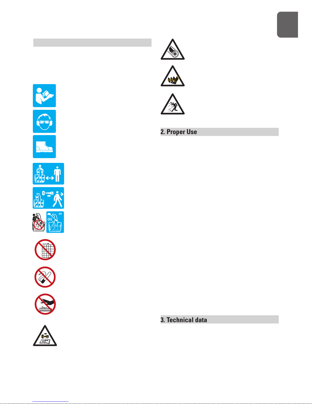
1. Notes on Safety and Warnings
The rating plate on your machine may
show symbols. These represent important
information about the product or instructions
on its use.
Read these instructions for use
carefully.
Wear eye protection.
Wear hearing protection.
Wear safety footwear.
Keep bystanders away.
Stop engine and remove ignition
key prior to leaving the operator’s
position.
Only use clean-out tool to clear
blockage. Never use your hands.
It is forbidden to remove or tamper
with the protection devices and
safety devices.
Do not smoke or have open flames.
Do not touch a hot muffler, gear
housing or cylinder.
Stop engine, remove key, read
manual before making any repairs
or adjustments.
G
B
Keep hands out of the inlet and
discharge openings while machine
is running.
Stay away from rotating augers.
Never direct discharge towards
persons or property.
2. Proper Use
Your new snow thrower will more than satisfy
your expectations. It has been manufactured
under stringent quality standards to meet
superior performance criteria. You will find it
easy and safe to operate, and with proper care, it
will give you many years of dependable service.
Carefully read through this entire operator’s
manual before using your new snow thrower. Take
special care to heed the cautions and warnings.
Your snow thrower has many features that
will make your job faster and easier. Safety,
performance, and dependability have been
given to top priority in the development of this
machine, making it easy to maintain and operate.
The Engine manufacturer is responsible
for all engine-related issues with regards to
performance, power rating, specifications,
warranty and service. Please refer to the Engine
Manufacturer’s owner’s/operator’s manual,
packed separately with your unit, for more
information.
3. Technical data
Clearing Width 56 cm
Intake Height 40.0cm
Auger Dia. 24.0cm
Impeller Dia. 24,3cm
Speed 5F+2R
Page 4

4
4. Notes on Safety
General Safety Rules
Understand your machine
Allow operation only by properly trained adult,
never children.
Read and understand the operator’s manual
and labels affixed to the machine. Learn its
application and limitations as well as the
specific potential hazards peculiar to it.
Be thoroughly familiar with the controls and
their proper operation. Know how to stop the
machine and disengage the controls quickly.
Make sure to read and understand all the
instructions and safety precautions as outlined
in the Engine Manufacturer’s Manual, packed
separately with your unit. Do not attempt to
operate the machine until you fully understand
how to properly operate and maintain the
Engine and how to avoid accidental injuries
and/or property damage.
Work area
Never start or run the engine inside a closed
area. The exhaust fumes are dangerous,
containing carbon monoxide, an odorless and
deadly gas. Operate this unit only in a well
ventilated outdoor area.
Never operate the machine without good
visibility or light.
Never operate the machine on a steep slope.
Personal safety
Do not operate the machine while under the
influence of drugs, alcohol, or any medication
that could affect your ability to use it properly.
Dress properly. Wear heavy long pants, boots
and gloves. Do not wear loose clothing, short
pants, and jewelry of any kind. Secure long
hair so it is above shoulder level. Keep your
hair, clothing and gloves away from moving
parts. Loose clothes, jewelry or long hair can
be caught in moving parts.
Use safety equipment. Always wear eye
protection. Safety equipment such as a dust
mask, hard hat, or hearing protection used for
appropriate conditions will reduce personal
injuries.
Check your machine before starting it. Keep
guards in place and in working order. Make
sure all nuts, bolts, etc. are securely tightened.
Disengage all clutches and shift into neutral
before starting the engine.
Never operate the machine when it is in need
of repair or is in poor mechanical condition.
Replace damaged, missing or failed parts
before using it. Check for fuel leaks. Keep the
machine in safe working condition.
Never tamper with safety device. Check their
proper operation regularly.
Do not use the machine if the engine’s throttle
control does not turn it on or off. Any gasoline
powered machine that can not be controlled
with the engine throttle control is dangerous
and must be replaced.
Form a habit of checking to see that keys
and adjusting wrenches are removed from
machine area before starting it. A wrench or
a key that is left attached to a rotating part of
the machine may result in personal injury.
Stay alert, watch what you are doing and use
common sense when operating the machine.
Do not overreach. Do not operate the machine
while barefoot or when wearing sandals or
similar lightweight footwear. Wear protective
footwear that will protect your feet and
improve your footing on slippery surfaces.
G
B
Page 5

5
Keep proper footing and balance at all times.
This enables better control of the machine in
unexpected situations.
Avoid accidental starting. Be sure the engine’s
throttle control is off before transporting the
machine or performing any maintenance or
service on the unit. Transporting or performing
maintenance or service on a machine with its
throttle control on invites accidents.
Fuel safety
Fuel is highly flammable, and its vapors can
explode if ignited. Take precautions when
using to reduce the chance of serious personal
injury.
When refilling or draining the fuel tank, use
an approved fuel storage container while in
a clean, well-ventilated outdoor area. Do not
smoke, or allow sparks, open flames or other
sources of ignition near the area while adding
fuel or operating the unit. Never fill fuel tank
indoors.
Keep grounded conductive objects, such as
tools, away from exposed, live electrical parts
and connections to avoid sparking or arcing.
These events could ignite fumes or vapors.
Always stop the engine and allow it to cool
before filling the fuel tank. Never remove
the cap of the fuel tank or add fuel while the
engine is running or when the engine is hot.
Do not operate the machine with known leaks
in the fuel system.
When practical, remove the machine from the
truck or trailer and refuel it on the ground. If
this is not possible, then refuel the machine on
a trailer with a portable container, rather than
from a fuel dispenser nozzle.
Loose the fuel tank cap slowly to relieve any
pressure in the tank.
Keep the nozzle in contact with the firm of the
fuel tank or container opening at all times until
fueling is complete. Do not use a nozzle lockopen
device.
Never over fill fuel tank. Fill tank to no more
than 12.5mm (1/2”) below the bottom of the
filler neck to provide space for expansion as
the heat of the engine and/or sun cause fuel
to expand.
Replace all fuel tank and container caps
securely and wipe up spilled fuel. Never
operate the unit without the fuel cap securely
in place.
Avoid creating a source of ignition for spilled
fuel. If fuel is spilled, do not attempt to start
the engine but move the machine away
from the area of spillage and avoid creating
any source of ignition until fuel vapors have
dissipated. Serious personal injury can occur
when fuel is pilled on yourself or your clothes
which can ignite. Wash your skin and change
clothes immediately.
Store fuel in containers specifically designed
and approved for this purpose.
Never fill containers inside a vehicle or on a
truck or trailer bed with a plastic liner. Always
place containers on the ground away from
your vehicle before filling.
Store fuel in a cool, well-ventilated area.
Safely away from sparks, open flames or other
sources of ignition.
Never store fuel or machine with fuel in the
tank inside a building where fumes may
reach a spark, open flame, or other sources
of ignition, such as a water heater, furnace,
clothes dryer and the like. Allow the engine to
cool before storing in any enclosure.
G
B
Page 6

6
Machine use and care
Never pick up or carry a machine while the
engine is running.
Do not force the machine. Use the correct
machine for your application. The correct
machine will do the job better and safer at the
rate for which it was designed.
Do not change the engine governor settings
or over-speed the engine. The governor
controls the maximum safe operating speed
of the engine.
Do not put hands or feet near rotating parts.
Avoid contact with hot fuel, oil, exhaust fumes
and hot surfaces. Do not touch the engine or
muffler. These parts get extremely hot from
operation. They remain hot for a short time
after you turn off the unit. Allow the engine
to cool before doing maintenance or making
adjustments.
After striking a foreign object, stop the
engine, remove the wire from the spark
plug, thoroughly inspect the machine for
any damage, and repair the damage before
restarting and operating the machine.
If the machine should start to make an unusual
noise or vibration, immediately shut off the
engine, disconnect the spark plug wire, and
check for the cause. Unusual noise or vibration
is generally warning of trouble.
Use only attachments and accessories
approved by the manufacturer. Failure to do
so can result in personal injury.
Maintain the machine. Check for misalignment
or binding of moving parts, breakage of parts
and any other condition that may affect the
machine’s operation. If damaged, have the
machine repaired before use. Many accidents
are caused by poorly maintained equipment.
Keep the engine and muffler free of grass,
leaves, excessive grease or carbon build up to
reduce the chance of a fire hazard.
Never douse or squirt the unit with water or
any other liquid. Keep handles dry, clean and
free from debris. Clean after each use.
Observe proper disposal laws and regulations
for gas, oil, etc. to protect the environment.
Store idle machine out of the reach of children
and do not allow persons unfamiliar with
the machine or these instructions to operate
it. Machine is dangerous in the hands of
untrained users.
Service
Before cleaning, repair, inspecting, or adjusting
shut off the engine and make certain all
moving parts have stopped. Always make
sure the engine’s throttle control is in its STOP
position. Disconnect the spark plug wire, and
keep the wire away from the plug to prevent
accidental starting.
Have your machine serviced by qualified repair
personnel using only identical replacement
parts. This will ensure that the safety of the
machine maintained.
Specific Safety Rules
Do not operate without wearing adequate
winter outer garments.
Do not use the machine on a roof.
Do not run the engine indoors, except when
starting the engine and for transporting
the snow thrower in or out of the building.
Open the outside doors; exhaust fumes are
dangerous.
G
B
Page 7

7
Always check overhead and side clearances
carefully before operation. Always be aware of
traffic when operating along streets or curbs.
Thoroughly inspect the area to be worked.
Keep the working area clean and free of toys,
doormats, newspapers, sleds, boards, wires
and other foreign objects, which could be
tripped over or thrown by the auger/impeller.
Check for weak spots on docks, ramps or
floors.
Plan your snow-throwing pattern to avoid
discharge toward people or areas where
property damage can occur.
Do not operate near drop-offs, ditches, or
embankments. Machine can suddenly turn
over if a wheel is over the edge of a cliff or
ditch, or if an edge caves in.
Keep all bystanders, children, and pets at least
23m (75 feet) away. If you are approached,
stop the unit immediately.
Use a grounded three-wire extension cord and
receptacle for all machines with electric start
engines.
Check clutch and brake operation frequently.
Adjust and service as required. All motion of
drive wheels and auger/impeller must stop
quickly when control levers are released.
Let engine and machine adjust to outdoor
temperature before starting to clear snow.
Stay alert for hidden hazards or traffic.
Do not overload machine capacity by
attempting to clear snow at too fast of a rate.
Do not throw snow any higher than necessary.
Adjust auger housing height to clear gravel
or crushed rock surfaces. Exercise extreme
caution when operating.
Exercise caution to avoid slipping or falling,
especially when operating in reverse. Never
operate machine at high transport speeds
on slippery surfaces. Always look down and
behind before and while backing.
Do not operate on steep slopes. Do not
clear snow across the face of slopes. Keep
all movement on slopes slow and gradual.
Do not make sudden changes in speed or
direction. Use a slow speed to avoid stops or
shifts on slopes. Avoid starting or stopping
on a slope. Do not park machine on a slope
unless absolutely necessary. When parking on
a slope, always block the wheels.
Disengage power to the auger/impeller when
transporting or not in use.
Disengage all control levers and stop engine
before you leave the operating position
(behind the handles). Wait until the auger/
impeller comes to a complete stop before
unclogging the chute assembly, making any
adjustments, or inspections.
Hand contact with the rotating impeller inside
the discharge chute is the most common
cause of injury associated with snow throwers.
Do not unclog chute assembly while engine
is running. Shut off engine and remain behind
handles until all moving parts have stopped
before unclogging. Never put your hand in
the discharge or collector openings. Always
use the clean-out tool provided to unclog the
discharge opening.
G
B
Page 8
8
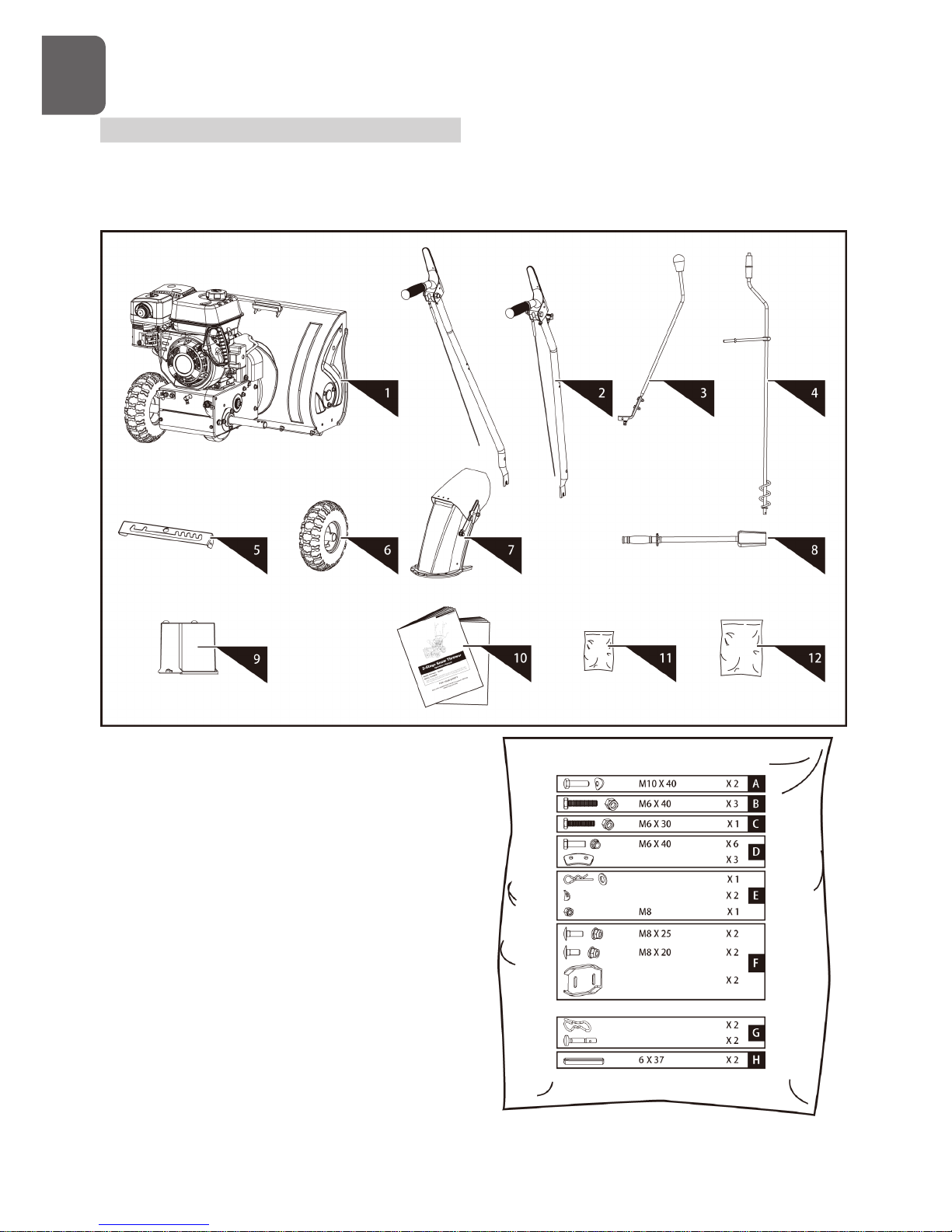
5. Overview Instrument Components
The snow thrower comes partially assembled and is shipped in carefully packed carton. After all
the parts have been removed from the carton, you should have:
Attention : All reference to the left or right side
of the snow thrower are from the operator’s
position.
1. Snow Thrower Unit
2. Handlebars (1 pair)
3. Shift Lever
4. Chute Crank Lever
5. Control Panel
6. Wheel
7. Discharge Chute
8. Chute Clean-Out Tool
9. Battery (if so equipped)
10. Operator’s Manual & Engine Manual
11. Engine Hardware Bag
12. Snow Thrower Hardware Bag, Including
G
B
Page 9
9
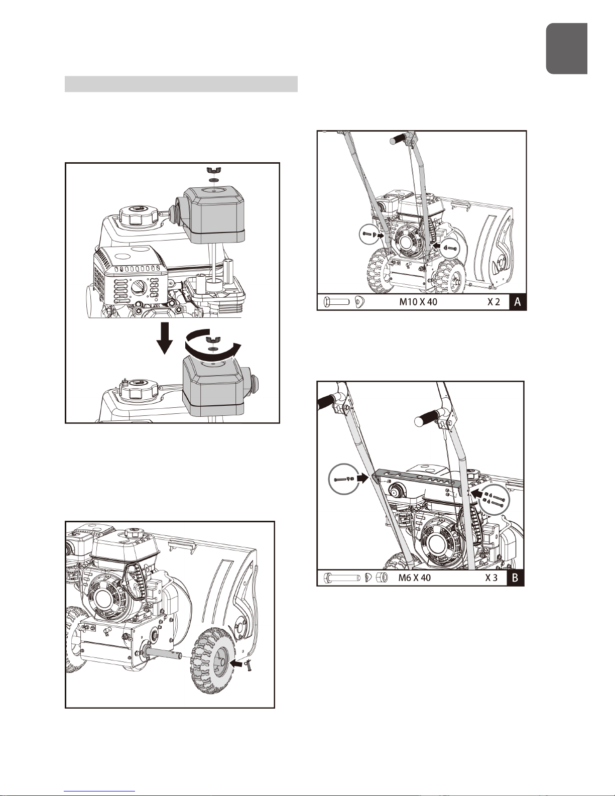
6. Assembly
Following the assembly directions below, you will
assemble the snow thrower in a few minutes
Engine
1. Remove wing nut and washer from the air
filter cover.
2. Rotate the air filter cover by 180o so that
the primer faces outside.
3. Install air filter cover and tighten wing nut.
Handlebars
1. Remove the axle pin and slide the wheel on the
axle. Insert the axle pin through the hole in the
wheel hub and through the hole in the axle.
2. Align the holes in the handlebars with the side
plates and secure handlebars with the screws and
the washers until they are finger tight.
3. Secure control panel to the handlebars with
screws, washers and nuts until they are
finger tight.
4. Ensure that the handles are at the same
height, and then tighten all the fasteners
securely.
G
B
Page 10
10
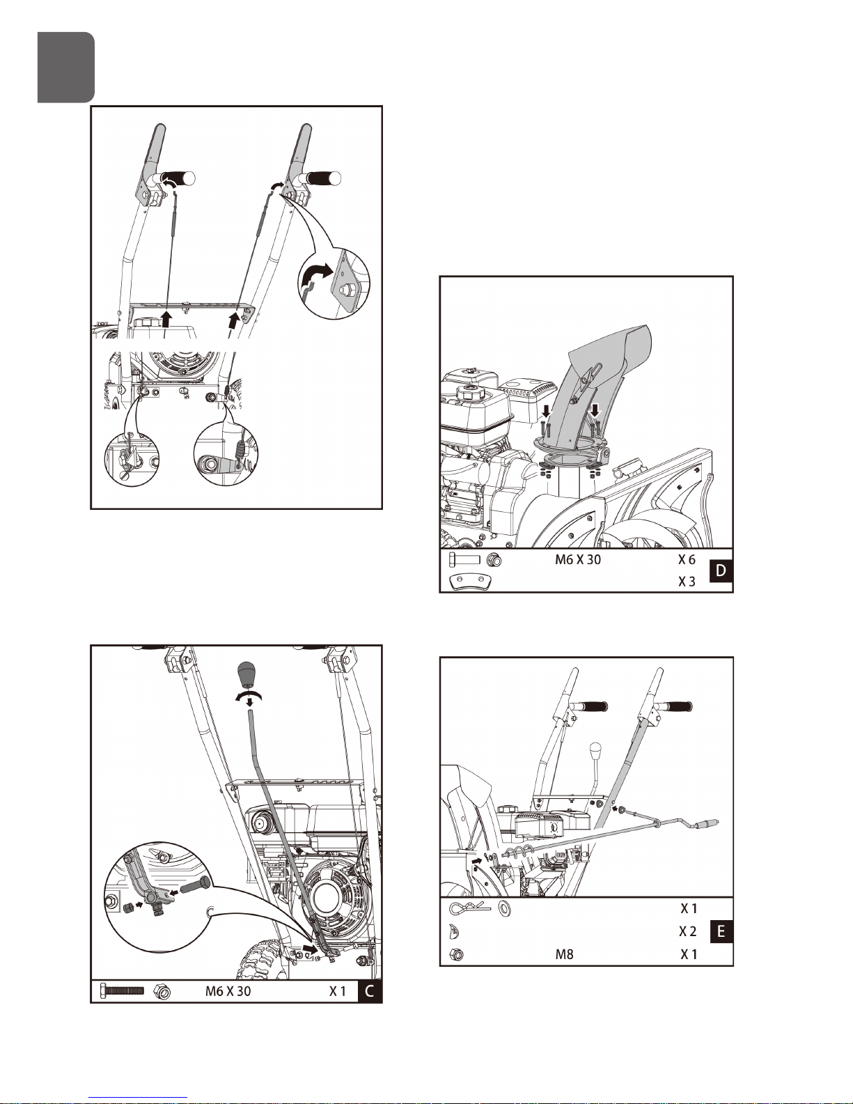
5. Slide the control cables through the holes in
the control panel. Make certain the cables are
seated properly in roller guides when hook the
cables to the clutch levers.
Speed Shift Linkage
Remove the knob to slide the shift lever
through the slot in the control panel. Secure
shift lever to the shift arm with screw and nut.
Replace the knob.
Discharge Chute
1. Grease underside of discharge chute ring (if
not already greased).
2. Install discharge chute over opening in the
auger housing and secure with fasteners.
G
B
Page 11
11
3. Secure the upper crank lever bracket (attached
to the crank lever) to the upper left side of the
handlebar with a locknut and two curved washers.
4. Apply grease to the spiral of the crank lever.
5. Insert the spiral end of the crank lever into the
lower bracket and secure with the flat washer and
clevis pin.
Tires
The tires are over-inflated at factory for
shipping purposes. Check the pressure in the
tires. Reduce or Increase equally in both tires
to the manufacturer’s recommended pressure.
Under any circumstance do not
exceed manufacturer’s recommended
pressure. Excessive pressure when
seating beads may cause tire/rim assembly
to burst with force sufficient to cause serious
injury. Refer to side wall of tire for recommended
pressure.
Equal tire pressure should be maintained
at all times. If the tire pressure is not
equal in both tires, the machine may not
travel in a straight path and the scraper
blade may wear unevenly.
Keep tires free of gasoline and oil,
which can harm rubber.
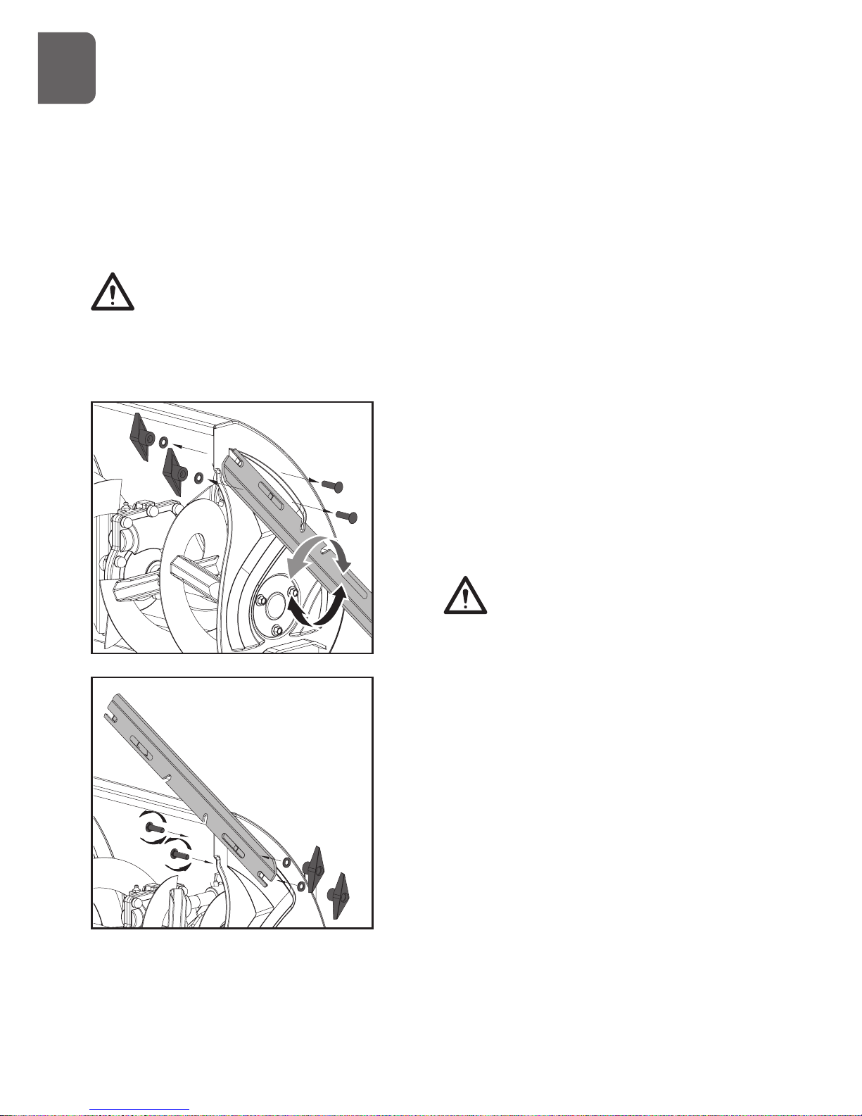
Skid Shoes
1. Move the machine to a level surface.
2. Support the auger blades so that they are 3mm
(1/8”) off the ground.
3. Check the scraper blade adjustment. The scraper
blade should be 3mm (1/8”) above and parallel to
a level ground. To adjust the scraper blade, loosen
the seven mounting screws (two on each side),
level the scraper blade, and tighten the mounting
screws.
4. Attach both skid shoes to the auger side plates
with the screws and nuts. Move the skid shoes
down as far as possible. Be sure both skid shoes
are adjusted evenly. Tighten securely.
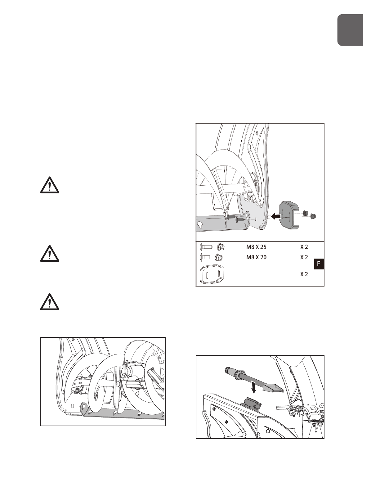
Chute Clean-Out Tool
G
B
Page 12
12
Fasten the clean-out tool to the mounting clip
on the rear of the auger housing.
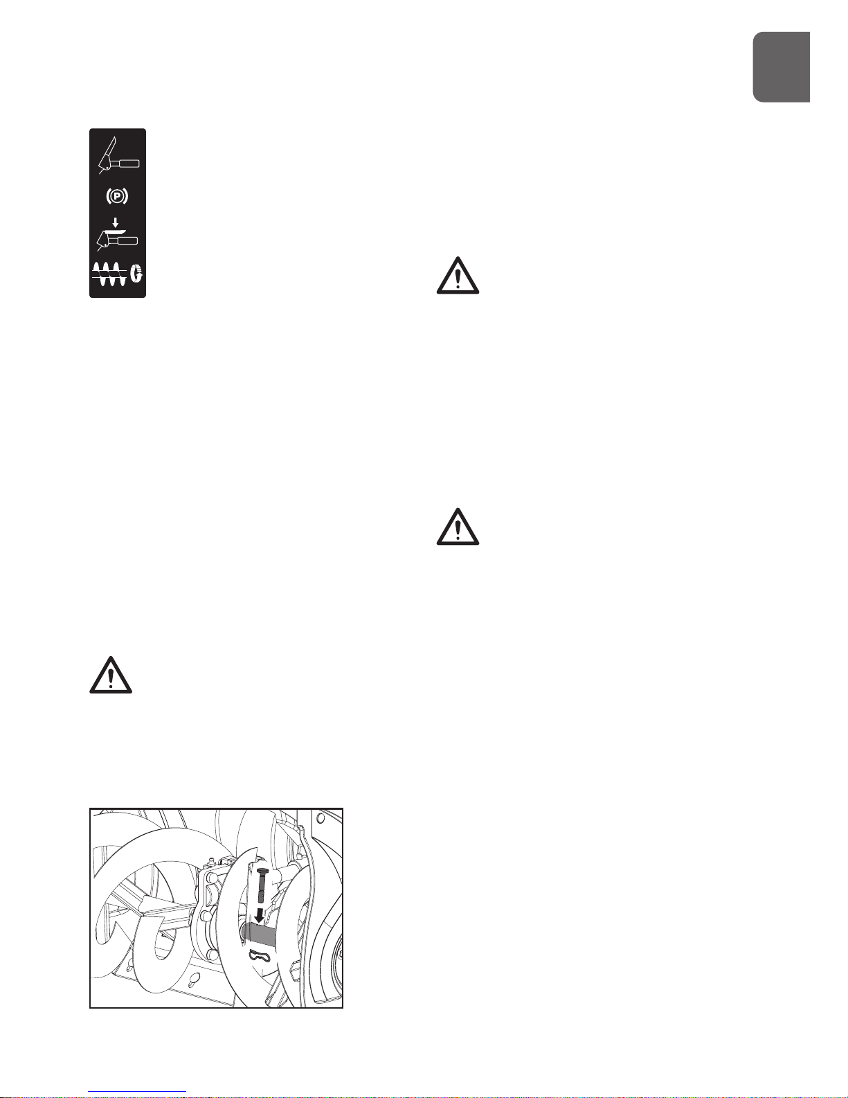
Replacement Shear Pins
A pair of replacement auger shear pins and
clevis pins are included with your snow thrower.
Store them in a safe place until needed.
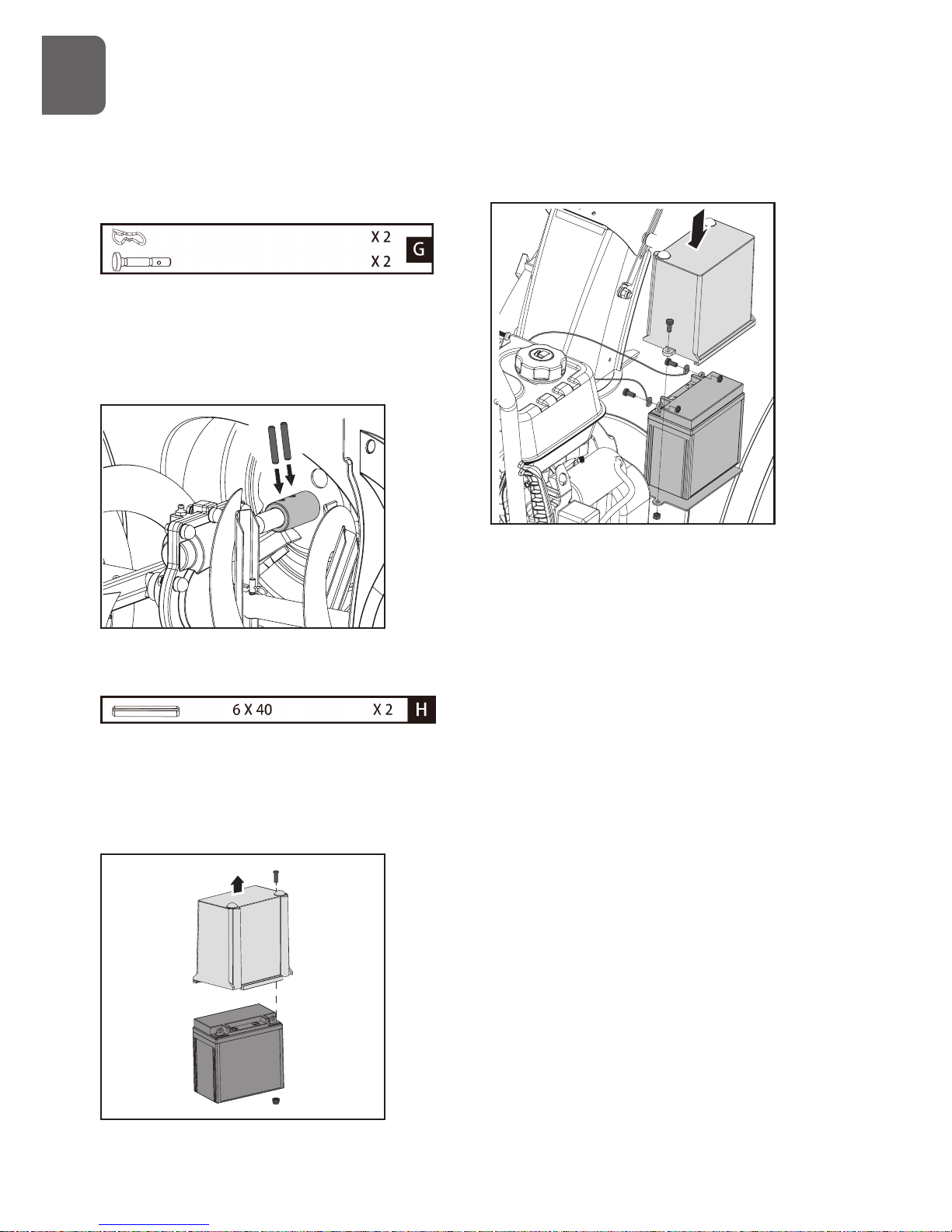
Spare Roll Pins
The impeller is secured to the impeller shaft
with roll pins.
Two 6x40 roll pins for impeller are supplied
as spare in the hardware bag. Store them in a
safe place until needed.
Battery (if so equipped)
1. Remove the battery cover by loosening
the screw and nut.
2. Take battery out of the tray.
3. Replace battery on the tray.
4. Connect positive (red) battery cable to the
battery terminal first, then negative (black) battery
cable. Check that all cable connectors are tight.
5. Reinstall battery cover and tighten the screw and
nut.
G
B
Page 13
13
7. Operation
1
2
3
4
5
6
7
8
9
10
11
12
13
14
15
16
17
18
19
20
21
22
23
24
25
26
27
28
G
B
Page 14
14
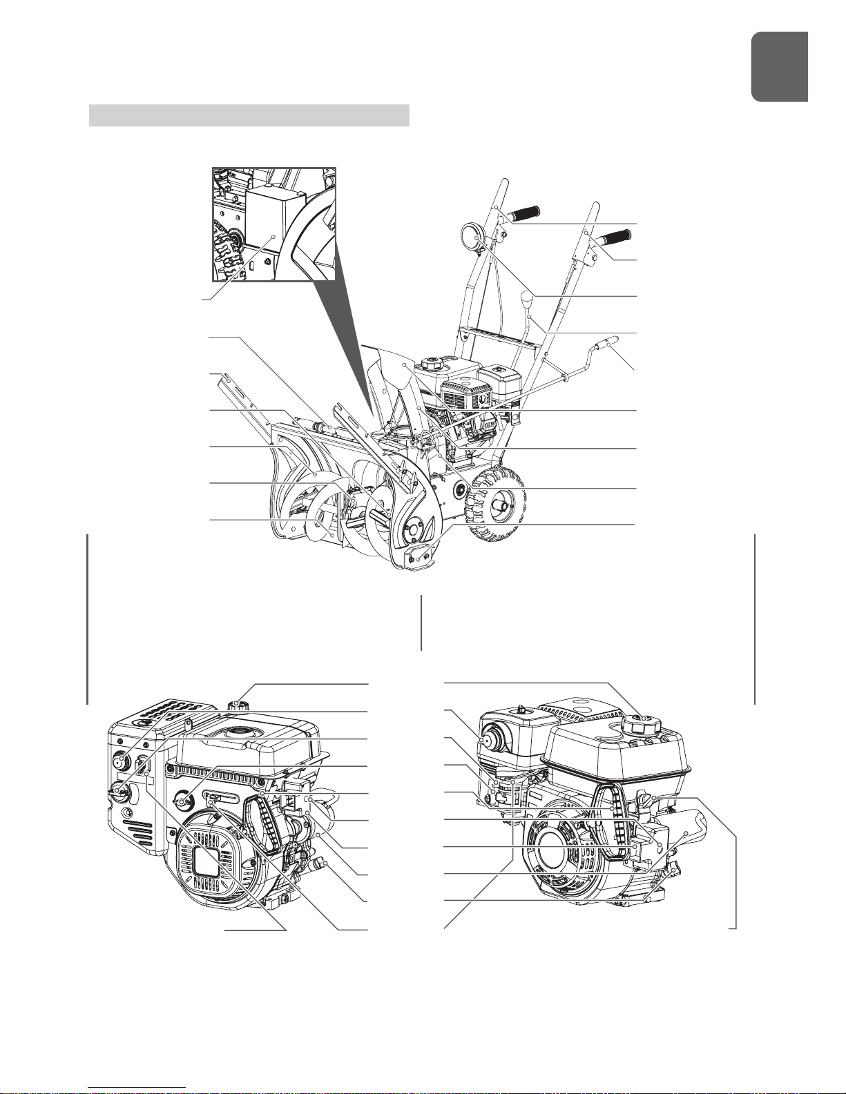
1. Battery
2. Chute Clean-Out Tool
3. Drift Cutters
4. Shear Pins
5. Auger
6. Auger Gearcase
7. Scraper Blade
8. Drive Clutch Lever
9. Auger Clutch Lever
10. Headlight
11. Speed Shift Lever
12. Chute Crank
13. Chute Deflector
14. Discharge Chute
15. Belt Cover
16.Skid Shoes
17. Fuel Filler Cap
18. Primer
19. Choke
20. Fuel Shutoff Valve
21. Recoil Starter
22. Electric Start Button
23. Power Cord Plug
24. Electric Starter
25. Engine Oil Fill Cap w/ Dipstick
26. Throttle Lever
27. Safety Ignition Switch
28. ON/OFF Switch
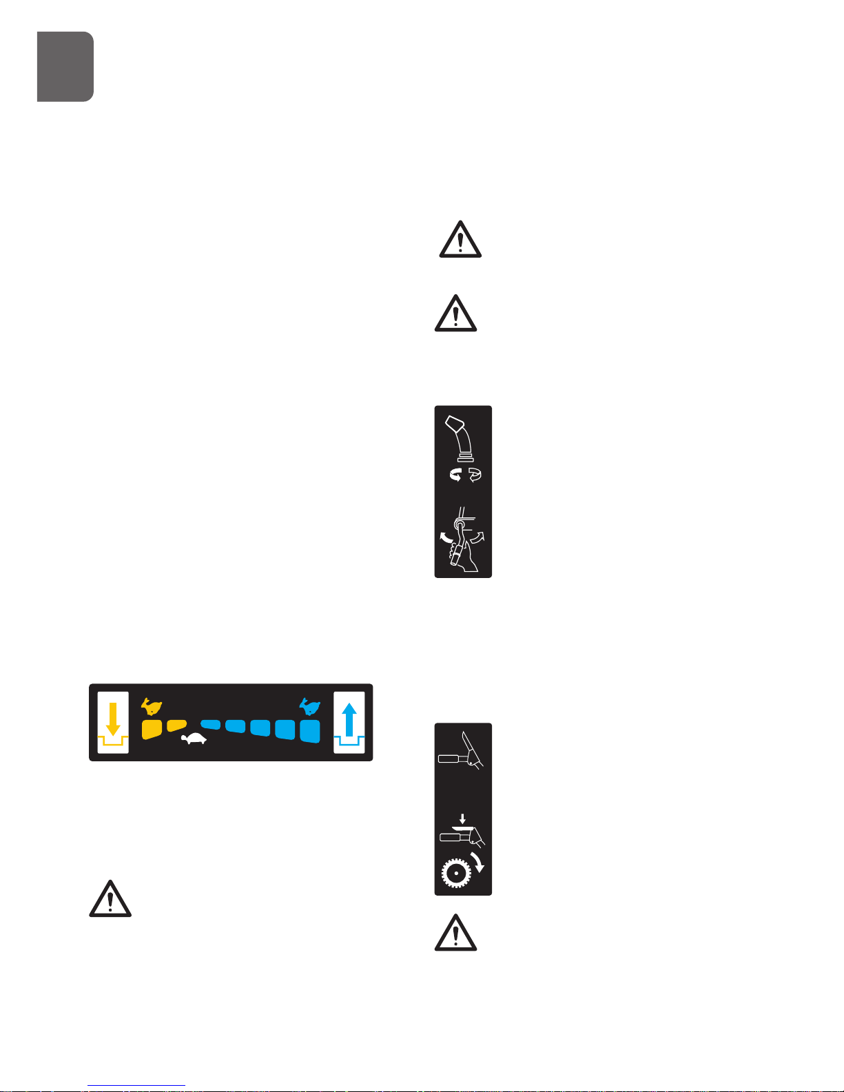
Speed Shift Lever
The speed shift lever has 7 positions: 5 forward
speeds and 2 reverse. To change speeds, move
the speed shift lever to the desired position.
The lever locks in a notch at each speed
selection.
Always release the drive clutch lever
before changing speeds. Failure to
do so will result in damage to the
snow thrower.
Slower speeds are for heavier snow and faster
speeds are for light snow and transporting the
snow thrower. It is recommended that you use
a slower speed until you are familiar with the
operation of the snow thrower.
If the engine slows down under a
load or the wheels slip, shift the
machine into a lower gear.
If the front of the machine rides up,
shift the machine into a lower gear.
If the front continues to ride up, lift
up on the handles.
Discharge Chute Crank Lever
Rotate the discharge crank lever
clockwise to move the discharge
chute to the left; counterclockwise
to move the chute to the right.
Chute Deflector Handle
Move the deflector handle forward to move
the snow stream down; move it rearward to
move the snow stream up.
Drive Clutch Lever
Squeeze the clutch lever against
the handgrip to engage the wheel
drive. Release to disengage
Always release the drive clutch lever
before changing speeds. Failure to
do so will result in damage to the
snow thrower.
G
B
Page 15
15
Auger Clutch Lever
Squeeze the clutch lever against
the handgrip to engage the auger
and start snow throwing action.
Release to disengage.
Scraper Blade & Skid Shoes
The scraper blade allows better contact with
the surface being cleared. It also prevents
damage to the housing from normal use.
The skid shoes are located on each side of
the auger housing and control the distance
between the scraper blade and the ground.
Adjust skid shoes equally to keep the scraper
blade level with the ground.
The scraper blade & skid shoes are subject
to wear and damage. Both scraper blade and
skid shoes are adjustable to compensate for
wear. They should be checked and adjusted
periodically. Replace when necessary.
Damage to auger housing will result
if scraper blade wears down too far.
Both scraper blade and skid shoes have two
wear edges. When one side wears out, they
can be rotated 180o to use the other edge.
Shear Pins
The augers are secured to the auger shaft with
shear pins and clevis pins. If the auger should
strike a foreign object or ice jam, the snow
thrower is designed so that the pins may shear,
preventing damage to any other components. If
augers will not turn, check to see if the pins have
sheared. Replace the shear pins if necessary.
Do not substitute. Use only original
equipment shear pins as supplied
with your snow thrower.
Auger
When engaged, the augers rotate and draw
snow into the auger housing.
Discharge Chute
Snow drawn into the auger housing is
discharged out the discharge chute.
Chute Clean-Out Tool
Never use your hands to clear a
clogged discharge chute . Shut off
engine and remain behind handles
until all moving parts have stopped
before unclogging.
The chute clean-out tool is conveniently
fastened to the rear of the auger housing
with a mounting clip. Should snow and ice
become lodged in the discharge chute during
operation, proceed as follows to safely clean
the discharge chute and chute opening:
1. Release the auger clutch lever and shut off
the engine.
2. Remove the clean-out tool from the clip which
secures it to the rear of the auger housing.
3. Grasp the tool firmly by the handle and
push and twist the tool into the discharge
chute to dislodge the blockage.
4. Refasten the clean-out tool to the mounting
clip on the rear of the auger housing.
5. Make sure the discharge chute is pointed
in a safe direction (no vehicles, buildings,
people, or other objects are in the direction
of discharge). Restart the engine. While
G
B
Page 16
16
standing in the operator’s position (behind
the snow thrower), engage the auger
control for a few seconds to clear any
remaining snow and ice from the auger
housing and the discharge chute.
Headlight (if so equipped)
The headlight provides added
safety in low-visibility conditions.
Turn the headlight switch to the
ON position to activate.
Drift Cutters (if so equipped)
Drift cutters break up snow drifts that are
taller than the auger housing and direct the
snow into the auger. Store the drift cutters on
the auger housing when not in use. Reposition
drift cutters so they face forward as shown.
Wing nuts should be fastened on the outside
of the auger housing.
Fuel Shutoff Valve
Always operate the snow thrower with the
fuel shut-off valve in the OPEN position. Close
the valve when you do not use the machine.
Throttle Lever
Move the throttle lever to the right to increase
the engine speed; move it to the left to
decrease the engine speed. Move the throttle
lever to the STOP position to stop the engine.
Choke
Engage choke by rotating lever to FULL
position whenever you are starting a cold
engine. As engine warms up, gradually rotate
the choke to the OFF position.
Do not use choke to start a warm engine.
Never use choke to stop engine.
Primer
Press the primer to pump additional fuel from
the carburetor to the cylinder for improved
cold weather starting.
Recoil Starter
The recoil starter is on the back side of the
engine. Pull the recoil starter handle to start
the engine.
Safety Ignition Switch (if so equipped)
Insert the safety ignition key for engine to
start and run. To stop the engine, remove the
key.
ON/OFF switch (if so equipped)
Used to stop the engine. Move switch to OFF
G
B
Page 17
17
position to stop engine. Place switch in ON
position for engine to start and run.
Ignition Switch (12V DC electric start)
The ignition switch is operated by a removable
key which has 3 positions of STOP, RUN and
START.
Electric Starter & Start Button (if so equipped)
The electric starter will start a properly choked
and cranked engine when the key is turned
(12V DC) or start button (120V or 230V AC) is
pushed.
To start the machine, connect the electric
starter to an electric power source with an
approved extension cord and press the start
button.
Thoroughly inspect the electrical cord
before using the machine. If the cord is
damaged, do not operate the machine. Replace or
repair the damaged cord immediately.
Connect extension cord to the electric
starter plug-in first and then to a power
outlet; disconnect the extension cord from
the power outlet first and then from the machine.
To prevent damaging the electric starter, do
not run it more than 5 continuous seconds
each time you try to start. Wait 10 seconds
between each attempt.
Adjustments
Skid Shoes
Position the skid shoes based on surface
conditions. For removal of snow in normal
conditions, such as a paved driveway or
sidewalk, place skid shoes in the higher
position to give a 3mm (1/8”) clearance
between the scraper blade and the ground.
Use a middle or lower position when the area
to be cleared is uneven, such as a gravel
driveway.
It is not recommended to operate the snow
thrower on gravel as it can easily pick up
and throw by the impeller, causing personal
injury or damage to the snow thrower and
surrounding property.
If you choose to operate the snow thrower
on a gravel surface, use extra caution and
keep the skid shoes in position for maximum
clearance between the ground and the scraper
blade.
Always adjust skid shoes after
adjusting scraper blade to prevent
premature wear to scraper blade or
damage to auger housing.
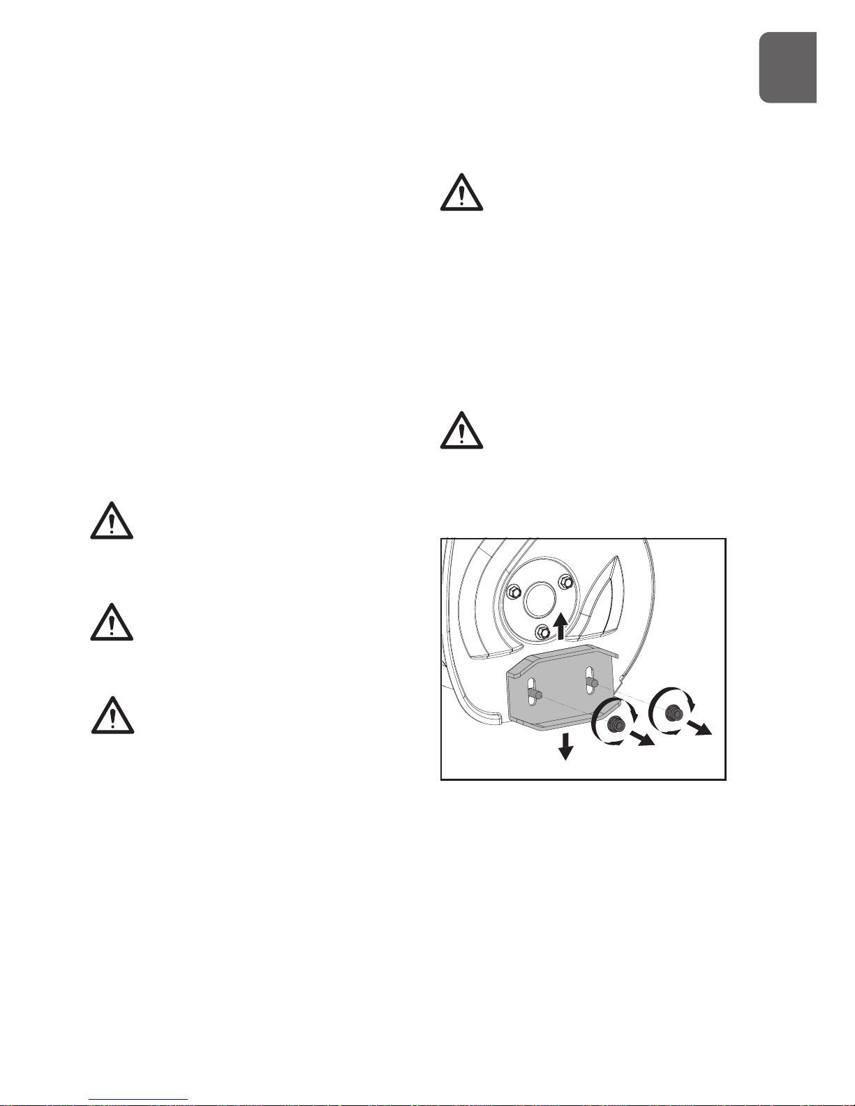
To adjust the skid shoes:
1. Loosen the four hex nuts (two on each
side) and carriage bolts. Move skid shoes
to desired position.
2. Make sure the entire bottom surface of
skid shoe is against the ground to avoid
uneven wear on the skid shoes.
3. Retighten nuts and bolts securely.
Auger Clutch and Drive Clutch
When auger clutch lever or drive clutch lever
G
B
Page 18
18
is released and in the disengaged position, the
cable should have very little slack.
Auger must stop within 5 seconds when the
auger clutch lever is released. If auger clutch
does not engage or disengage properly, adjust
auger clutch before operation.
If the snow thrower’s drive is disengaging
intermittently during operation, or it drives
when you release the drive clutch lever, adjust
the drive clutch before operation.
Both auger clutch and drive clutch can be
adjusted as follows:
1. Loosen jam nut on adjustment turnbuckle.
Turn the adjustment turnbuckle up and
down to increase cable tension or provide
more slack.
2. Retighten jam nut.
Chute Bracket
If the spiral at the bottom of the chute crank
lever is not fully engaging with the chute
assembly, the chute bracket can be adjusted.
To do so:
1. Loose the two nuts which secure the chute
bracket and reposition it slightly.
2. Retighten the nuts.
Freewheeling and Self-Propelling
Use the axle lock pin to lock or unlock the
right or left wheel. Lock both wheels to
increase traction; unlock one wheel to allow
for easier turning of the unit; unlock both
wheels for freewheeling.
G
B
Page 19

19
To unlock wheel, slide it inward and insert the
axle pin through the outer axle hole, but not
through the wheel hub.
To lock wheel, slide it outward and insert the
axle pin through the hole in the wheel hub and
the outer axle hole.
Starting and Stopping the Engine
Before starting the engine, check engine
oil level and ensure the engine is served as
described in the Engine Manual with the
snow blower.
Cold Start – Electric Starter (120V or 230 AC)
(if so equipped)
The engine is equipped with both A.C. electric
starter and a recoil starter. The electric starter
is equipped with a three-wire power cord and
plug and is designed to operate at the voltage
shown in the label.
Do not use the electric starter if your
household voltage different from the one
shown on the electric starter.
1. Insert safety ignition key into ignition slot
until it clicks. Do not turn the key.
2. Be sure fuel shutoff valve is in the OPEN
position.
3. Move choke control to FULL position.
4. Push the primer 2 or 3 times. When temperature
is below -25oC (15oF), additional priming may
be needed. When temperature is above 10oC
(50oF), priming is not necessary.
Over priming may cause flooding,
preventing the engine from starting.
If you do flood the engine, wait a few
minutes before attempting to start and do not push
the primer.
Some snow engine is not equipped with
primer as priming is not needed for such
engine.
5. Connect the extension cord to the engine.
6. Plug the other end of the extension cord
into a three-wire grounded receptacle.
7. Push starter button until engine starts.
To prevent damaging the electric starter, do
not run it more than 5 continuous seconds
each time you try to start. Wait 10 seconds
between each attempt.
8. When the engine starts, release the starter
button and slowly move the choke control
to the OFF position.
9. Disconnect the extension cord from the
receptacle first, then from the engine.
Cold Start – Electric Starter (12V DC) (if so
equipped)
1. Be sure fuel shutoff valve is in the OPEN position.
2. Move choke control to FULL position.
3. Push the primer 2 or 3 times. When temperature
is below -25oC (15oF), additional priming may be
needed. When temperature is above 10oC (50oF),
priming is not necessary.
Over priming may cause flooding,
preventing the engine from starting. If you
do flood the engine, wait a few minutes
G
B
Page 20

20
before attempting to start and do not push the
primer.
Some snow engine is not equipped with
primer as priming is not needed for such
engine.
4. Turn ignition key to the START position
until engine starts.
To prevent damaging the electric starter, do
not run it more than 5 continuous seconds
each time you try to start. Wait 10 seconds
between each attempt.
5. When the engine starts, release the ignition
key into RUN position and slowly move the
choke control to the OFF position.
Cold Start – Recoil Starter
1. Be sure fuel shutoff valve is in the OPEN
position.
2. Place ON / OFF switch in ON position.
3. Rotate choke control to FULL position.
4. Push the primer 2 or 3 times. When
temperature is below -25oC (15oF),
additional priming may be needed. When
temperature is above 10oC (50oF), priming
is not necessary.
Over priming may cause flooding,
preventing the engine from starting. If you
do flood the engine, wait a few minutes
before attempting to start and do not push the
primer.
5. Grasp recoil starter handle and pull rope
out slowly until it pulls harder. Let rope
rewind slowly.
6. Pull rope with a rapid continuous full arm
stroke. Do not allow starter rope to snap
back.
7. Repeat steps 5 and 6 until engine starts.
8. When the engine starts, release the recoil
starter handle and slowly move the choke
control to the OFF position.
Warm Start
Follow the steps above, keeping the choke
control in the OFF position and do not use
primer.
Allow the engine to warm up for a few
minutes, engine will not develop full power
until it has reached normal operating
temperature.
In snowy and cold conditions, some
controls and moving parts may freeze. Do
not use excessive force when trying to
operate frozen controls. If you have difficulty
operating any control or part, start the engine and
let is run for a few minutes.
Snow Throwing Tips
It is easier and more efficient to remove snow
immediately after it falls.
The best time to remove snow is the early
morning. At this time the snow is usually dry
and has not been exposed to the direct sun
and warming temperatures.
Slightly overlap each successive path to
ensure all snow will be removed.
For large areas, start in the middle and throw
snow to each side, so snow is not cleared
more than once.
For extremely heavy snow, reduce the width
of snow removal by overlapping previous path
and moving slowly.
Throw snow downwind whenever possible.
Keep engine clean and clear of snow during
use. This will help air flow and extend engine
life.
After snow-throwing is completed, let the
engine run for a few minutes to help dry
off the moisture on the engine and prevent
G
B
Page 21

21
moving parts from freezing. Engage the auger
to clear any remaining snow from inside
the housing. Rotate the discharge chute to
prevent it from freezing. Stop the engine, wait
for all moving parts to stop, and remove all
ice and snow from the snow thrower. With
the engine off, pull the recoil starter handle
several times to prevent the recoil starter from
freezing up.
8. Maintenance and Care
Engine
Refer to the Engine Operator’s Manual.
Lubrication
Auger Gearbox
The gearbox was filled with lubricant to the
proper level at the factory. Unless there is
evidence of leakage or service has been
performed on the gearbox, no additional
lubricant should be required. If lubricant is
required, use GL-5 or GL-6, SAE85-95, EP
gear oil lubricant. Do not use synthetic oil.
General Lubrication
Lightly lubricate all moving parts of the
machine at the end of the season or every 25
operating hours.
Do not allow grease or oil get on friction
disc, friction plate or belts. Do not
excessively oil the machine; extra oil may
enter the traction drive and cause the traction
drive belt to slip.
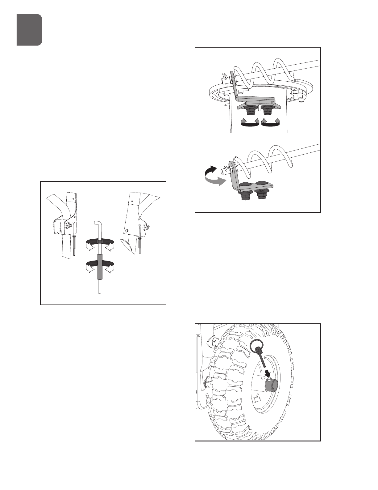
When lubricating auger shaft, remove shear
pins to apply oil inside the shaft and around
spacers and flange bearings found at either
end of the shaft.
Remove the wheels to apply grease
the wheel shaft.
Battery (if so equipped)
Battery is maintenance-free. Do not tamper with or
attempt to open battery.
Keep battery and its terminals clean.
1. Remove battery cover.
2. Detach the negative (black) battery cable from
the battery first to prevent a short circuit, then the
positive (red) battery cable.
3. Take the battery out of the tray.
G
B
Page 22

22
4. Remove corrosion from battery terminals
and cable connections with a wire brush,
then wash with weak baking soda solution.
5. Apply a thin coat of grease or petroleum
jelly to terminals and cable ends to retard
corrosion.
6. Attach and tighten the positive (red)
battery cab first, then the negative (black)
battery cable.
7. Place the battery on the tray and Install
the cover.
Off-Season Storage
Refer to the Engine Manual for
information on storing your engine
At the end of the season or if the snow
thrower will not be used for 30 days longer,
follow the storage instructions below.
1. Run the engine until the fuel lines and
carburetor are empty and it stops due to
lack of fuel.
2. Remove the safety ignition key and allow
the engine to cool.
3. Lubricate the machine as instructed.
4. Clean the exterior of the engine and the
snow thrower thoroughly.
5. Touch up all rusted or chipped paint
surfaces; sand affected areas before
painting, and use a rust preventative to
prevent the metal parts from rusting.
6. Tighten all loose screws, bolts, and
locknuts. Repair or replace any damaged
parts.
7. Cover the machine and store it in a clean,
dry place out of the reach of children.
Belt Replacement
Auger Belt
If the auger belt becomes worn, oil-soaked,
or otherwise damaged, proceed as follows to
replace the belt.
1. To prevent spillage, remove all fuel from
tank by running engine until it stops.
Remove the key to avoid unintended
starting and allow unit to cool completely.
2. Remove the two screws that hold the belt
cover in place and set the cover aside.
3. Roll the auger belt(s) off the engine pulley.
4. Carefully pivot the snow thrower up and
forward so that it rests on the auger housing.
G
B
Page 23

23
5. Remove the frame cover from the underside
of the snow thrower by removing the screws
which secure the cover.
6. Remove the belt(s) from around the auger
pulley, and slip the belt(s) between the
support bracket and the auger pulley.
7. Replace the auger belt(s) by following
instructions in reverse order.
Drive Belt
If the drive belt becomes worn, oil-soaked, or
otherwise damaged, proceed as follows to
replace the belt.
1. To prevent spillage, remove all fuel from
tank by running engine until it stops.
Remove the key to avoid unintended
starting and allow unit to cool completely.
2. Remove the two screws that hold the belt
cover in place and set the cover aside.
3. Remove the belt as follows.
a. Roll the auger belt off the engine pulley.
b. Pivot the idler pulley toward the right
to relieve tension.
c. Lift the drive belt off engine pulley.
4. Carefully pivot the snow thrower up and
forward so that it rests on the auger housing.
5. Remove the frame cover from the underside
of the snow thrower by removing the screws
which secure the cover.
G
B
Page 24

24
6. Slip the drive belt off the pulley and between
friction wheel and friction wheel disc.
7. Remove and replace belt in the reverse order.
Holding down the drive clutch lever
will ease reinstallation of the belt.
If an assistant is available, you can also
separate the auger housing from the frame
assembly to replace belts.
1. Shut off engine, remove key, disconnect spark
plug wire and allow unit to cool completely.
2. Remove belt cover.
3. Remove the clevis pin and washer from
the chute crank lever to remove it from the
lower branket.
4. Remove bottom cover to avoid bending it
when tipping unit apart.
5. Remove the screws securing auger
housing to the frame (two on each side).
Tip auger housing and frame apart.
6. Replace auger belt or drive belt.
7. Tip auger housing and frame back together
and secure with screws.
Holding down the auger clutch lever
will ease reconnection of the auger
housing and frame.
8. Place belt(s) onto engine sheave(s).
9. Reinstall the chute crank lever.
Friction Wheel Replacement
If the snow thrower fails to drive with the drive
clutch engaged, and performing the clutch
control cable adjustment fails to correct the
problem, the friction wheel may need to be
replaced.
1. To prevent spillage, remove all fuel from tank by
running engine until it stops. Remove the key to
avoid unintended starting and allow unit to cool
completely.
2. Carefully pivot the snow thrower up and forward
so that it rests on the auger housing.
3. Remove the frame cover(s) from the underside of
the snow thrower by removing the screws which
secure the cover(s).
3. Remove the right-hand wheel by removing
the axle lock pin.
G
B
Page 25

25
5. Carefully remove the hex nut which secures the
hex shaft to the snow thrower frame and lightly tap
the shaft’s end to dislodge the ball bearing from the
right side of the frame. Be careful not to damage
the threads on the shaft.
6. Remove the other bearing from the left side
of the frame by removing the snap ring.
7. Carefully position the hex shaft downward
and to the left before carefully sliding the
friction wheel assembly off the shaft.
8. Follow the previous steps in reverse order
to reassemble.
If you only want to replace the rubber ring,
proceed as follows:
1. Remove the six screws which secure the
friction wheel’s side plates together.
2. Remove the rubber ring from between the
plates.
3. Reassemble the side plates with a new
rubber ring.
G
B
Page 26

26
When reassembling the friction wheel
assembly, make sure that rubber ring is
centered and seated properly between the
side plates. Tighten each screw only one rotation
before turning the wheel clockwise and
proceeding with the next screw on the other side
of the wheel. Repeat this process several times to
ensure the plates are secured with equal force
between 90N.m(6 ft-lbs) and 130N.m(9 ft-lbs).
4. Slide the friction wheel assembly back
onto the hex shaft. Make sure the shift
lever pin is in place in the bearing housing.
Follow the steps above in reverse order to
reassemble components.
Charging Battery (if so equipped)
Follow the instructions below to charge
battery:
1. Remove battery cover.
2. Disconnect negative (black) battery cable
first, then positive (red) battery cable.
3. Take battery out of the tray and place it on
bench or other well-ventilated place.
4. Connect positive (+) lead of charger to
positive (+) terminal, and negative (-) lead
to negative (-) terminal.
5. Charge the battery at two and a half amps
for ten hours.
6. Reinstall battery into unit.
9 . Transport
To travel from one work area to another:
Always shut off engine, remove key, and
close fuel shut-off valve when transporting
unit on a truck or trailer. Do not transport
machine while engine is running.
Use extra care when loading or unloading unit
onto trailer or truck.
Secure unit chassis to transport vehicle. Never
secure from rods or linkages that could be
damaged.
G
B
10. ENVIRONMENTAL
Recycle unwanted materials instead
of disposing of them as waste. All
tools, hoses and packaging should
be resorted, taken to the local
recycling center and disposed off in
an environment-friendly safe way.
Page 27

27
11. TROUBLE SHOOTING
Problem Cause Remedy
Electric starter does not
turn(on models so equipped)
1. Extension cord not connected.
2. The extension cord is worn,
corroded, or damaged.
3.The power outlet is not energized.
1. Connect the extension cord to
the outlet and/or the machine.
2.Replace the extension cord.
3. Have a qualified electrician
energize the outlet.
Engine fails to start 1. Choke not in CHOKE position.
2.Engine not primed.
3.Engine is flooded.
4.Fuel shut-off valve closed.
5. Throttle in STOP position or ON/
OFF switch is OFF.
6. Spark plug wire loose or
disconnected.
7.Fuel tank empty or stale fuel.
8.Faulty spark plug.
9.Safety ignition key is not inserted.
10. The engine oil level in the engine
crankcase is too low or too high
1. Move choke to CHOKE position.
2. Prime engine as instructed in
this manual.
3. Wait a few minutes before
restarting, do not prime.
4.Open fuel shut-off valve.
5. Move throttle to FAST position
or ON/OFF switch to ON Position.
6. Connect or tighten spark plug
wire.
7. Fill tank with clean, fresh
gasoline.
8. Clean, adjust gap, or replace.
9. Insert safety ignition key.
10. Add or drain oil to adjust the oil
level in the engine crankcase.
Engine idles or runs
roughly
1. Engine running on CHOKE.
2. Fuel tank is nearly empty or stale
fuel.
3.Contaminated fuel supply.
4.Carburetor out of adjustment.
5.Engine over-governed.
6. The fuel shutoff valve is not
completely open or blockage in
fuel line.
7.Spark plug wire loose.
8.Faulty spark plug.
9. The engine oil level in the engine
crankcase is too low or too high.
1. Move choke lever to RUN
position.
2. Fill tank with clean, fresh
gasoline.
3. Replace with clean fuel.
4 . Contact a qualified repair
personnel.
5. Contact a qualified repair
personnel.
6. Open the fuel shutoff valve or
clean fuel line.
7. Tighten spark plug wire.
8. Clean, adjust gap, or replace.
9. Add or drain oil to adjust the oil
level in the engine crankcase.
The engine overheats Carburetor not adjusted properly. Contact a qualified repair
personnel.
Excessive vibration Loose parts or damaged parts. Tighten all fasteners or replace
damaged parts.
G
B
Page 28

28
Loss of power 1. Spark plug wire loose.
2.Gas gap vent hole plugged.
3.Dirty or clogged muffler.
1. Tighten spark plug wire.
2.Clean or replace fuel cap.
3.Clean or replace muffler.
Loss of traction drive 1. Drive control cable not adjusted
properly.
2.Drive belt loose or damaged.
3.Friction wheel worn.
1. Adjust drive control cable.
2.Replace drive belt.
3.Replace friction wheel.
Loss of snow discharge or
slowing of snow discharge
1. Discharge chute clogged.
2.Augers or impeller jammed.
3. Auger control cable not adjusted
properly.
4.Auger belt loose or damaged.
5.Shear pin(s) sheared.
6. Throttle not in FAST position
when throwing snow.
7.Moving too fast to clear the snow.
8.Throwing too much snow.
9. Trying to remove extremely heavy
or wet snow.
10.Auger is frozen in place.
1. Unclog discharge chute.
2. Remove debris or foreign object
from augers or impeller.
3.Adjust auger control cable.
4.Replace auger belt.
5.Replace with new shear pin(s).
6.Move throttle to FAST position.
7.Shift into a lower gear.
8.Reduce speed and width of
swath.
9. Do not overload with extremely
heavy or wet snow.
10. Move unit to a warm place to
thaw.
Discharge chute either
does not lock into place or
does not move
1. The discharge chute control not
adjusted properly.
2.Chute assembly incorrectly
1. Adjust the discharge chute
control.
2. Disassemble chute control and
reassemble as instructed in this
manual.
Machine does not properly
clear the snow of the surface
1. The skid shoes and/or scraper
blade not adjusted properly.
2.The pressure in the tires not equal.
1. Adjust the skid shoes and/or the
scraper blade.
2. Check and adjust the pressure
in one or both tires.
G
B
Page 29

29
E
E
1. SÜMBOLID
Seadme andmesildil võidakse kasutada sümboleid.
Need näitavad olulist infot toote või selle
kasutamise kohta.
Need juhised tuleb tähelepanelikult läbi
lugeda.
Kanda tuleb kaitseprille.
Kasutada kuulmekaitsevahendeid.
Jalga tuleb panna kaitsejalatsid.
Läheduses ei tohi viibida kõrvalisi
isikuid.
Kasutaja peab enne seadme
juurest lahkumist seiskama mootori
ja eemaldama süütevõtme.
Ummistuse kõrvaldamiseks tuleb
alati kasutada puhastustööriista.
Seda ei tohi kunagi teha käega.
Keelatud on eemaldada kaitse- ja
ohutusseadiseid või muuta nende
konstruktsiooni.
Seadme lähedal ei tohi suitsetada ega
kasutada lahtist tuld.
Kuuma summutit, reduktori korpust või
silindrit ei tohi puudutada.
Enne seadme remontimist või
reguleerimist tuleb alati seisata mootor
ja eemaldada süütevõti. Vt juhendit.
Seadme töötamise ajal tuleb jälgida, et
kätt ei panda sissevõtu- ja väljutuskoha
juurde.
Hoida pöörlevast tigumehhanismist
eemale.
Lund ei tohi kunagi väljutada inimeste
või asjade suunas.
2. SISSEJUHATUS
See lumepuhur ületab kõik teie ootused. Selle
seadme tootmisel on parimate tööomaduste
tagamiseks järgitud rangeid kvaliteedistandardeid.
Seda on lihtne ja ohutu kasutada ning õige
hooldamise korral töötab see veel palju aastaid.
Enne lumepuhuri kasutuselevõtmist tuleb
kogu kasutusjuhend tähelepanelikult läbi
lugeda. Eriti tuleb tähelepanu pöörata
ettevaatusmeetmetele ja hoiatustele.
Lumepuhuril on palju omadusi, mis teevad selle
kasutamise kiiremaks ja kergemaks. Selle seadme
väljatöötamisel seati eesmärgiks ohutus, jõudlus ja
töökindlus, nii et hooldamine ja kasutamine on
lihtne.
Mootori tootja vastutab kõige eest, mis on seotud
mootoriga: jõudlus, nimivõimsus, tehnilised
andmed, garantii ja hooldus. Lisateave on esitatud
mootori tootja koostatud kasutusjuhendis, mis on
eraldi pakendis seadmega kaasas.
3. Tehnilised andmed
Puhastuslaius 56 cm
Sissevõtu kõrgus 40,0 cm
Teo läbimõõt 24,0 cm
Rootori läbimõõt 24,3 cm
Käik 5 edasi + 2 tagasi
Page 30

30
4. OHUTUS
Üldised ohutusnõuded
Seadme tundmaõppimine
Seadmega on lubatud töötada ainult täiskasvanutel,
kes seda tunnevad. Kunagi ei tohi seda seadet
kasutada lapsed.
Kasutusjuhend ja seadmel paiknevad sildid tuleb
läbi lugeda, nii et neist on aru saadud. Tundma
tuleb õppida nii seadme kasutamist ja piiranguid
kui ka võimalikke ohte.
Põhjalikult tuleb tutvuda juhtseadiste ja nende õige
kasutamisega. Õppida selgeks, kuidas saab
seadme peatada ja juhtseadised kiiresti vabastada.
Seadme komplekti kuuluvast mootori tootja
kasutusjuhendist tuleb kindlasti läbi lugeda kõik
juhiseid ja ohutusnõuded. Seadet ei tohi kasutama
hakata enne, kui olete täielikult aru saanud sellest,
kuidas mootor õigesti tööle rakendada ja kuidas
seda hooldada.
Samuti tuleb teada, kuidas vältida kehavigastusi ja/
või varalist kahju.
Tööpiirkond
Mootorit ei tohi kunagi käivitada ega lasta sellel
töötada kinnises ruumis. Heitgaas on ohtlik,
sisaldades vingugaasi, mis on lõhnatu ja eluohtlikult
mürgine gaas.
Seda seadet tohib kasutada ainult hea
õhuvahetusega välistingimustes.
Seadmega ei tohi kunagi töötada halva nähtavuse
korral või pimedas.
Seadet ei tohi kunagi kasutada järsul kallakul.
Kasutaja ohutus
Seadmega ei tohi töötada narkootiliste ainete,
alkoholi või mistahes ravimi mõju all olles, mis võib
mõjutada kasutaja võimet seadet õigesti kasutada.
Kanda tuleb asjakohast riietust. Kasutada tuleb
tugevaid pikki pükse, saapaid ja kindaid. Rõivad ei
tohi olla liiga avarad, kanda ei tohi lühikesi pükse
ega mingeid ehteid. Pikad juuksed tuleb kinni
panna, et need oleksid õlgadest kõrgemal. Hoida
juuksed, rõivad ja kindad liikuvatest osadest eemal.
Liiga avarad rõivad, ehted ja pikad juuksed võivad
takerduda seadme liikuvate osade vahele.
Kasutada tuleb kaitsevarustust. Töötades
tuleb alati kanda kaitseprille. Asjakohane
kaitsevarustus (nt tolmurespiraator, kaitsekiiver
või kuulmekaitsevahendid) aitab vähendada
tervisekahjustuste ohtu.
Enne töölerakendamist tuleb seade üle kontrollida.
Kaitsekatted peavad olema oma kohale paigaldatud
ja töökorras. Kontrollida, et kõik mutrid, poldid jms
on tugevalt kinni. Enne mootori käivitamist tuleb
vabastada kõik sidurid ja seada käiguvahetushoob
neutraalasendisse.
Seadet ei tohi kunagi kasutada, kui see vajab
remonti või on tehniliselt halvas seisukorras.
Kahjustunud, puuduvad või rikkis osad tuleb enne
seadme kasutamist uutega asendada. Kontrollida,
et ei esine kütuseleket. Jälgida, et seade on alati
töökorras ja ohutu.
Kunagi ei tohi omavoliliselt muuta ohutusseadiseid.
Regulaarselt tuleb kontrollida, et need
funktsioneerivad õigesti.
Seadet ei tohi kasutada, kui mootori seguklapi
hoova abil ei saa seda sisse ja välja lülitada.
Bensiinimootoriga seade on alati ohtlik, kui seda
ei saa seguklapi hoova abil lülitada. Sel juhul tuleb
seguklapi hoob enne seadme kasutamist välja
vahetada.
Harjumuseks peab saama, et enne
käivitamist kontrollitakse, kas mutrivõtmed
ja reguleerimistööriistad on seadme juurest
eemaldatud. Seadme pöörleva osa külge jäetud
E
E
Page 31

31
tööriist või mutrivõti võib põhjustada kehavigastuse.
Seadmega töötades tuleb olla tähelepanelik, jälgida
oma tegevust ja kasutada tervet mõistust.
Liiga palju ei tohi ette kummarduda. Seadmega ei
tohi töötada paljajalu ega kandes sandaale vms
kergeid jalatseid. Kanda tuleb turvajalatseid, mis
kaitsevad jalgu ja pakuvad libedatel pindadel
kindlamat jalgealust. Alati tuleb seista kindlal
pinnal ja töötada stabiilses asendis. See võimaldab
seadet ootamatus olukorras paremini kontrollida.
Vältida tuleb tahtmatut käivitumist. Enne seadme
transportimist, reguleerimist või hooldustööde
tegemist tuleb alati üle kontrollida, et seguklapi
hoob on väljalülitatud asendis. See, kui seguklapi
hoob on transportimise, reguleerimise või
hooldustööde ajal sisselülitatud asendis, võib
põhjustada õnnetusjuhtumi.
Kütuse ohutu käitlemine
Kütus on väga tuleohtlik ja selle aur võib süttimisel
plahvatada. Raskete kehavigastuste
ohu vähendamiseks tuleb rakendada
ettevaatusmeetmeid.
Kütusepaaki on lubatud täita või tühjendada ainult
välistingimustes, puhtas ja hea õhuvahetusega
kohas, kasutades nõuetekohast kütusekanistrit.
Selle koha lähedal, kus kütust lisatakse või
seadet kasutatakse, ei tohi suitsetada ega
tekitada sädemeid, kasutada lahtist tuld või muid
süütamisohtlikke asju.
Kunagi ei tohi kütust lisada sisetingimustes.
Sädemete või elektrikaare vältimiseks tuleb
maandatud pingealtid esemed (näiteks tööriistad)
hoida eemal pingestatud elektriahelatest ja
ühendustest, mis on katmata. Muidu tekib heitgaasi
või bensiiniauru süttimise oht.
Enne kütusepaagi täitmist tuleb mootor alati seisata
ja lasta sellel jahtuda. Siis, kui mootor töötab või on
töötamisest veel soe, ei tohi eemaldada ütusepaagi
korki ega lisada paaki kütust. Seadet ei tohi
kasutada, kui kütusesüsteemis on leke.
Kui see on võimalik, tuleb seade kütuse lisamiseks
veokilt või haagiselt maapinnale tõsta. Kui see ei
ole võimalik, tuleb haagisel olevasse seadmesse
kütust lisada teisaldatavast kanistrist, mitte tankuri
püstolist.
Kütusepaagi kork tuleb lahti keerata aeglaselt, et
kütusepaak jõuaks rõhu alt vabaneda.
Tankuri püstolit tuleb kuni täitmise lõpetamiseni
hoida pidevalt kokkupuutes kütusepaagi või kanistri
ava servaga. Kasutada ei ole lubatud fikseeritava
avamisseadisega püstolit.
Kunagi ei tohi kütusepaaki panna liiga täis. Paaki ei
tohi lisada rohkem kütust kui kuni 12,5 mm (1/2“)
allpool täiteava, et jätta ruumi kütuse paisumiseks
mootori ja/või päikese soojuse mõjul.
Seejärel tuleb kütusepaagi ja kanistri kork taas
kindlalt kinni keerata ning pühkida mahaloksunud
kütus ära. Seadet ei tohi kasutada, kui kütusepaagi
kork ei ole kindlalt kinni.
Vältida tuleb süütamisohtlike asjade sattumist mahaloksunud kütuse lähedale. Kui kütust on maha
loksunud, siis ei tohi mootorit käivitada, vaid seade
tuleb kütuseloigust eemale viia ja vältida igasugust
süttimisohtu, kuni kütuseaur on hajunud. Nahale või
riietele loksunud kütus võib süttida ja põhjustada
raskeid kehavigastusi. Nahk tuleb kohe puhtaks
pesta ja riided vahetada.
Kütust tuleb hoida spetsiaalsetes kanistrites, mis
on selleks otstarbeks lubatud.
Kanistreid ei tohi kunagi täita sõiduki sees ega
veoki või haagise plastkattega kastis. Kanistrid
tuleb enne täitmist alati paigutada sõidukist eemal
maapinnale.
Kütust tuleb hoida jahedas, hea õhuvahetusega
kohas, ohutult eemal sädemetest, lahtisest tulest
või muudest süütamisohtlikest asjadest.
E
E
Page 32

32
Kütust või seadet, mille paagis on kütust, ei tohi
kunagi hoida hoones, kus kütuseaur võib kokku
puutuda sädemete, lahtise tule või süütamisohtlike
asjadega (boiler, küttekolle, pesukuivati jms). Enne
seadme hoiulepanekut kinnisesse ruumi tuleb
mootoril alati lasta jahtuda.
Seadme kasutamine ja hooldamine
Seadet ei tohi kunagi üles tõsta ega kanda, kui
selle mootor töötab.
Seadet ei tohi üle koormata. Kasutada tuleb
konkreetseks tööks sobivat seadet. Seade töötab
kõige paremini ja ohutumalt, kui seda kasutatakse
ettenähtud koormusel.
Mootori pöörlemissageduse regulaatori seadistust
ei tohi muuta, samuti ei tohi mootorit käitada liiga
suurel kiirusel. Mootori pöörlemissageduse
regulaator tagab mootori maksimaalse ohutu
töökiiruse.
Käsi ja jalgu ei tohi panna seadme pöörlevate
osade lähedale.
Vältida tuleb kokkupuutumist kuuma kütuse, õli,
heitgaasi ja kuumade pindadega. Mootorit ja
summutit ei tohi puudutada. Need osad lähevad
töötamise ajal väga kuumaks ja on mõnda aega
kuumad ka pärast seadme väljalülitamist. Enne
hooldustööde tegemist või reguleerimist tuleb
mootoril lasta jahtuda.
Kui põrgatakse millegi vastu, siis tuleb mootor
seisata, võtta juhe süüteküünla küljest lahti ja
kontrollida põhjalikult üle, et seade ei ole saanud
kahjustada.
Enne taaskäivitamist ja tööleasumist tuleb
kahjustused ära parandada.
Kui seade hakkab tegema ebaharilikku müra
või vibreerima, tuleb mootor kohe välja lülitada,
ühendada süüteküünla juhe lahti ja selgitada välja
müra või vibratsiooni põhjus. Ebatavaline müra või
vibratsioon annab tavaliselt märku rikkest.
Kasutada võib ainult neid lisaseadiseid ja tarvikuid,
mida tootja on lubanud. Selle nõude eiramine võib
põhjustada kehavigastusi.
Seade tuleb hoida töökorras. Kontrollida, et liikuvad
osad on õiges asendis ja saavad vabalt liikuda.
Samuti tuleb kontrollida, et osad ei ole purunenud,
ning jälgida kõike muud, mis võib mõjutada seadme
tööd. Seadet võib kasutada alles siis, kui
kahjustused on parandatud. Paljud õnnetused
juhtuvad halvasti hooldatud seadme tõttu.
Mootor ja summuti tuleb tuleohu vähendamiseks
hoida puhas rohust, lehtedest, liigsest määrdest ja
tahmast.
Seadme peale ei tohi kunagi pritsida ega valada
vett ega muud vedelikku. Käepidemed tuleb hoida
kuivad, puhtad ja prahist vabad. Pärast iga
kasutuskorda tuleb seade puhastada.
Keskkonna kaitsmiseks tuleb jälgida bensiini, õli
jms jäätmekäitluse kohta kehtivaid õigusnorme.
Kui seadet ei kasutata, tuleb seda hoida sellises
kohas, kus lapsed seda kätte ei saa. Seadet ei tohi
lubada kasutada isikutel, kes seda ei tunne ega ole
tutvunud selle kasutusjuhendiga. Väljaõppeta
kasutaja käes on seade ohtlik.
Hooldus
Enne seadme puhastamist, remontimist,
ülevaatamist või reguleerimist tuleb mootor välja
lülitada ja kontrollida, et kõik liikuvad osad on
seiskunud. Alati tuleb üle kontrollida, et mootori
seguklapi hoob on asendis STOP. Ühendada
süüteküünla juhe lahti ning hoida juhe juhusliku
käivitumise vältimiseks süüteküünlast eemal.
Seadet võib lasta hooldada ainult asjakohase
kvalifikatsiooniga tehnikul, kes kasutab identseid
varuosi. Nii on seadme ohutus tagatud.
Seadmekohased ohutusnõuded
Seadmega ei tohi töötada isik, kes ei kanna
E
E
Page 33

33
sobivaid talverõivaid.
Seadet ei ole lubatud kasutada katusel.
Mootoril ei tohi lasta töötada siseruumis, välja
arvatud mootori käivitamise ajal ja lumepuhurit
hoonesse või välja teisaldades. Sel juhul tuleb
avada välisuksed, sest heitgaas on ohtlik.
Enne seadme kasutamist tuleb alati tähelepanelikult
kontrollida, et üleval ja külgedel jääb piisavalt vaba
ruumi. Tänavatel või teepeenardel töötades tuleb
alati jälgida liiklust.
Tööpiirkond tuleb põhjalikult üle vaadata.
Tööpiirkond tuleb hoida puhas, seal ei tohi olla
mänguasju, uksematte, ajalehti, kelke, lumelaudu,
juhtmeid ega mingeid muid esemeid, millele
lumepuhur võib otsa sõita või mille võib teo/
rootoriga eemale paisata.
Kontrollida tuleb nõrku kohti sildadel, kaldteedel ja
põrandatel.
Lumekoristuse marsruut tuleb plaanida nii, et
välditakse lume heitmist inimeste poole või
kohtadesse, kus võib tekkida varakahju.
Töötada ei tohi järsakute, kraavide või
kaldapealsete läheduses. Kui ratas liigub üle
järsaku või kraavi serva või serv variseb, võib
seade ootamatult ümber minna.
Kõik kõrvalised isikud, lapsed ja loomad tuleb hoida
vähemalt 23 m kaugusel. Kui keegi läheneb, tuleb
seade kohe seisata.
Elektrilise käivitiga mootori korral tuleb alati
kasutada kolmesoonelist maandatud pikendusjuhet
ja pistikupesa.
Regulaarselt tuleb kontrollida, et sidur ja pidur on
töökorras. Vajaduse korral tuleb neid reguleerida ja
hooldada. Veorataste ja teo/rootori liikumine peab
kiiresti lõppema, kui juhthoovad vabastatakse.
Enne lumekoristuse alustamist tuleb mootoril ja
seadmel lasta kohanduda välistemperatuuriga.
Tähelepanelik tuleb olla varjatud ohtude ja liikluse
suhtes.
Seadet ei tohi üle koormata, koristades lund liiga
suurel kiirusel.
Lund ei tohi heita kõrgemale, kui on vajalik.
Kruusa- või killustikupinna puhastamiseks tuleb teo
korpus seada kõrgemale ja seadmega töötades olla
väga ettevaatlik.
Töötades tuleb olla ettevaatlik, et vältida libisemist
ja kukkumist, eriti tagasikäigu korral. Libeda pinna
korral ei tohi seadmega kunagi liikuda liiga suurel
kiirusel. Enne tagurdamist ja tagurdamise ajal tuleb
vaadata alla ja tahapoole.
Järsul kallakul ei tohi seda seadet kasutada. Lund
ei tohi koristada kallakuga risti. Mistahes liikumine
peab kallakutel olema aeglane ja sujuv. Seadme
kiirust ja suunda ei tohi järsult muuta. Kasutada
tuleb aeglast käiku, et vältida kallakul peatumist ja
käiguvahetust.
Mootori käivitamist ja seiskamist tuleb kallakul
vältida.
Ilma hädavajaduseta ei tohi seadet kallakul parkida.
Kallakul parkimiseks tuleb rattad alati tõkestada.
Kui seadet ei kasutata või seda teisaldatakse, tuleb
vabastada teo/rootori jõuülekanne.
Enne seadme juhthoobade juurest lahkumist tuleb
kõik juhthoovad vabastada ja seisata mootor. Enne
ummistuste kõrvaldamist rennisüsteemist,
reguleerimist või kontrollimist tuleb alati oodata,
kuni tigu/rootor on täielikult seiskunud.
Lumepuhuri korral on kõige levinum vigastus, mis
saadakse, puudutades käega väljutusrennis
pöörlevat rootorit. Väljutusrennisüsteemi ei tohi
puhastada sel ajal, kui mootor töötab. Ummistuse
kõrvaldamiseks tuleb kõigepealt lülitada mootor
välja ja seejärel oodata käepidemete taga, kuni
liikuvad osad on seiskunud.
Kunagi ei tohi kätt panna väljutusavasse või koguri
avasse. Väljutusava ummistuse kõrvaldamiseks
tuleb alati kasutada puhastustööriista.
E
E
Page 34

34
5. TARNEKOMPLEKT
Lumepuhur tarnitakse osaliselt kokkupanduna ja korralikult pappkasti pakituna. Pärast kõigi osade kastist
väljavõtmist tuleb kontrollida, et kõik allnimetatud osad on olemas.
Tähelepanu.: Kõik viited lumepuhuri vasakule või
paremale küljele on tehtud kasutaja kohalt
vaadates.
1. Lumepuhur
2. Suunamiskäepidemed (1 paar)
3. Käiguvahetushoob
4. Renni tõstehoob
5. Juhtpaneel
6. Ratas
7. Väljutusrenn
8. Väljutusrenni puhastustööriist
9. Aku (kui kuulub komplekti)
10. Seadme kasutusjuhend ja mootori
kasutusjuhend
11. Mootori tarvikute kott
12. Lumepuhuri tarvikute kott, mis sisaldab järgmist:
E
E
Page 35

35
6. KOKKUPANEK
Kui järgitakse alljärgnevaid juhiseid, võtab
lumepuhuri kokkupanek vaid mõne minuti.
Mootor
1. Õhufiltri kattelt tuleb eemaldada tiibmutter ja
seib.
2. Keerata õhufiltri katet 180o võrra, nii et
eeltäitenupp jääb väljapoole.
3. Paigaldada õhufiltri kate ja keerata tiibmutter
kinni.
Suunamiskäepidemed
1. Eemaldada telje tihvt ja lükata ratas telje otsa.
Panna telje tihvt läbi rattarummus oleva ava ja
läbi teljes oleva ava.
2. Suunamiskäepidemete ja küljeplaatide avad
tuleb kohakuti seada ning keerata käepidemed
poltide ja seibidega käe jõul kinni.
3. Kinnitada juhtpaneel suunamiskäepidemete
külge, keerates poldid, seibid ja mutrid käe jõul
kinni.
4. Kontrollida, et käepidemed on ühel kõrgusel, ja
seejärel keerata kõik kinnitusdetailid tugevasti
kinni.
E
E
Page 36

36
5. Panna juhttrossid läbi juhtpaneeli avade. Trosside
ühendamisel sidurihoobadega tuleb kontrollida,
et trossid paiknevad juhtrullikutel õigesti.
Käiguvahetushoovastik
Käiguvahetushoova lükkamiseks läbi juhtpaneeli
pilu tuleb eemaldada nupp. Käiguvahetushoob
tuleb käiguvarda külge kinnitada poldi ja mutriga.
Panna nupp tagasi.
Väljutusrenn
1. Määrida väljutusrenni võru alumine pool (kui
see ei ole juba määritud).
2. Väljutusrenn tuleb paigaldada teo korpuses oleva
ava kohale ja kinnitada kinnitusdetailidega.
E
E
Page 37

37
3. Tõstehoova ülemine tugi (kinnitatud tõstehoova
külge) tuleb lukustusmutri ja kahe lainelise seibiga
kinnitada üleval suunamiskäepideme vasaku
poole külge.
4. Määrida tõstehoova spiraal.
5. Tõstehoova spiraali ots tuleb panna alumise toe
sisse ning kinnitada lameseibi ja splindi abil.
Rehvid
Transportimiseks on rehvides suurem rõhk.
Rehvirõhku tuleb kontrollida ja mõlemas rattas
võrdselt vajadust mööda alandada või tõsta.
Mingil juhul ei tohi ületada tootja soovitatud
rõhku. Liigne rõhk võib põhjustada
rehvi/ velje koostu lõhkemise jõuga, mis võib
tekitada raskeid vigastusi. Kontrollida rehvi
külgseinalt, et rõhk on soovitatud piirides.
Rehvide rõhk peab alati olema võrdne. Kui
mõlema ratta rehvirõhk ei ole sama, siis
ei pruugi seade liikuda sirgjooneliselt ja
kaabitera võib kuluda ebaühtlaselt.
Vältida tuleb bensiini või õli sattumist
rehvidele, sest need võivad kummit
kahjustada.
Juhttallad
1. Seade tuleb paigutada ühetasasele pinnale.
2. Teo terad tuleb toestada, et need jääksid
maapinnast 3 mm (1/8“) kõrgusele.
3. Kontrollida tuleb kaabitera seadistust. Kaabitera
peab paiknema maapinnast 3 mm (1/8“) kõrgusel
ja olema sellega paralleelne. Kaabitera
reguleerimiseks tuleb lahti keerata 7 kinnituskruvi
(kaks igal küljel), seada kaabitera horisontaalseks
ja seejärel keerata kinnituskruvid taas kinni.
4. Mõlemad juhttallad tuleb poltide ja mutritega
kinnitada teo küljeplaatide külge. Liigutada
juhttallad nii alla, kui on võimalik. Kontrollida, et
mõlemad juhttallad on seatud ühekaugele. Keerata
tugevasti kinni.
Väljutusrenni puhastustööriist
E
E
Page 38

38
Puhastustööriist tuleb kinnitada teokorpuse
tagaküljel oleva kinnitusklambri külge.
Varu-lõiketihvtid
Üks varupaar teo tihvte ja lõiketihvte on
lumepuhuriga kaasas. Need tuleb edaspidiseks
kindlas kohas alles hoida.
Varutihvtid
Rootor on võlli külge kinnitatud tihvtidega.
Kaks 6x40 mm tihvti on tarvikute kotis rootori jaoks
varuosana olemas. Need tuleb edaspidiseks
kindlas kohas alles hoida.
Aku (kui kuulub komplekti)
1. Eemaldada akukate, keerates poldi ja mutri lahti.
2. Võtta aku aluselt ära.
3. Panna aku alusele tagasi.
4. Aku klemmiga tuleb kõigepealt ühendada
plussjuhe (punane), seejärel miinusjuhe (must).
Kontrollida, et kõik elektrijuhtmed on kindlalt
kinnitatud.
5. Panna tagasi akukate ning keerata polt ja mutter
kinni.
E
E
Page 39

39
7. SEADME TUNDMAÕPPIMINE
1
2
3
4
5
6
7
8
9
10
11
12
13
14
15
16
17
18
19
20
21
22
23
24
25
26
27
28
E
E
Page 40

40
1. Aku
2. Väljutusrenni puhastustööriist
3. Hangelõikurid
4. Lõiketihvtid
5. Tigu
6. Teo reduktori korpus
7. Kaabitera
8. Veo sidurihoob
9. Teo sidurihoob
10. Esituli
11. Käiguvahetushoob
12. Renni tõstehoob
13. Renni suunamiskate
14. Väljutusrenn
15. Rihmakate
16. Juhttallad
17. Kütusepaagi täiteava kork
18. Eeltäitenupp
19. Õhuklapp
20. Kütuse sulgeventiil
21. Nöörkäiviti
22. Elektrikäiviti nupp
23. Toitejuhtme pistik
24. Elektriline käiviti
25. Mootori õlitäiteava kork / ja mõõtevarras
26. Seguklapi hoob
27. Ohutus-süütelukk
28. SISSE/VÄLJA lüliti
Käiguvahetushoob
Käiguvahetushooval on 7 asendit: 5 käiku edasi ja 2
tagasi. Käigu vahetamiseks tuleb käiguvahetushoob
seada soovitud asendisse. Käigu valimisel
fikseerub hoob vastavas sälgus.
Enne käiguvahetust tuleb alati vabastada
veo sidurihoob. Selle nõude
eiramine võib lumepuhurit kahjustada.
Aeglasemad käigud on raskema lume jaoks ning
kiiremad käigud kergema lume jaoks ja lumepuhuri
teisaldamiseks. Soovitatav on kasutada
aeglasemaid käike, kuni lumepuhuri kasutamisega
harjutakse.
Kui mootori pöörded koormuse
korral vähenevad või rattad libisevad,
siis tuleb sisse lülitada aeglasem käik.
Kui seadme esiosa tõuseb üles, siis
tuleb sisse lülitada aeglasem käik. Kui
esiosa tõuseb ikkagi üles, siis tuleb
seadet tõsta käepidemetest.
Väljutusrenni tõstehoob
Väljutusrenni vasakule pööramiseks
tuleb tõstehooba keerata päripäeva,
paremale pööramiseks aga vastupäeva.
Renni suunamiskatte käepide
Lumejoa madalamale suunamiseks tuleb
suunamiskatte käepide seada ettepoole, lumejoa
kõrgemale suunamiseks aga tahapoole.
Veo sidurihoob
Rataste veo sisselülitamiseks tuleb
sidurihoob vajutada vastu käepidet.
Väljalülitamiseks lasta lahti.
Enne käiguvahetust tuleb alati vabastada
veo sidurihoob. Selle nõude eiramine võib
lumepuhurit kahjustada.
E
E
Page 41

41
Teo sidurihoob
Teo sisselülitamiseks ja lume heitmise
alustamiseks tuleb sidurihoob vajutada
vastu käepidet. Väljalülitamiseks lasta
lahti.
Kaabitera ja juhttallad
Kaabitera võimaldab saavutada parema kontakti
puhastatava pinnaga. Samuti hoiab see tavapärase
kasutamise korral ära korpuse kahjustumist.
Juhttallad paiknevad teokorpuse kummalgi poolel
ning kontrollivad kaabitera ja maapinna
vahekaugust. Juhttaldasid tuleb reguleerida
võrdselt, et hoida kaabitera maapinnaga
paralleelsena.
Kaabitera ja juhttallad on kuluvad osad ja saavad
kahjustusi. Nii kaabitera kui ka juhttaldu saab
kulumise kompenseerimiseks reguleerida. Neid
tuleb regulaarselt kontrollida ja reguleerida.
Vajaduse korral välja vahetada.
Kui kaabitera on liialt kulunud, võib
teokorpus kahjustuda.
Nii kaabiteral kui juhttaldadel on kaks kulumisserva.
Kui üks serv kulub ära, saab neid pöörata 180o
võrra, et kasutada teist serva.
Lõiketihvtid
Teod on võlli külge kinnitatud tihvtide ja
lõiketihvtidega. Lumepuhur on konstrueeritud nii, et
kui tigu läheb millegi vastu või blokeerib selle jää,
siis võivad tihvtid murduda, hoides ära muude
komponentide kahjustumise. Kui teod ei pöörle,
siis tuleb kontrollida, ega tihvtid ei ole murdunud.
Vajaduse korral tuleb lõiketihvtid välja vahetada.
Neid ei tohi asendada. Kasutada on
lubatud ainult lumepuhuriga kaasas
olnud originaal-lõiketihvte.
Tigu
Sisselülitatud teod pöörlevad ja kannavad lund
teokorpusesse.
Väljutusrenn
Teokorpusse toodud lumi heidetakse välja
väljutusrenni kaudu.
Väljutusrenni puhastustööriist
Kunagi ei tohi ummistunud väljutusrenni
puhastada käega. Ummistuse
kõrvaldamiseks tuleb kõigepealt lülitada
mootor välja ja seejärel oodata käepidemete taga,
kuni liikuvad osad on seiskunud.
Renni puhastustööriist on kinnitusklambri abil
mugavalt kinnitatud teokorpuse taha. Kui lumi ja jää
kogunevad töö ajal väljutusrenni, siis tuleb
väljutusrenni ja renniava ohutuks puhastamiseks
tegutseda järgmisel viisil:
1. Teo sidurihoob tuleb vabastada ja mootor välja
lülitada.
2. Võtta teokorpuse tagaseina küljes olevast
kinnitusklambrist välja puhastustööriist.
3. Tugevalt käepidemest hoides lükata tööriist
väljutusrenni ja keerata seal ringi, et kõrvaldada
ummistus.
4. Puhastustööriist tuleb teokorpuse tagaküljel
oleva kinnitusklambri külge tagasi kinnitada.
5. Jälgida, et väljutusrenn on suunatud ohutus
suunas (väljutuspoolel ei ole sõidukeid, hooneid,
inimesi vms). Taaskäivitada mootor. Juhthoobade
juures (lumepuhuri taga) seistes tuleb
teo juhthoob lülitada mõneks sekundiks sisse, et
teokorpusest ja väljutusrennist eemaldada
allesjäänud lumi ja jää.
E
E
Page 42

42
Esituli (kui kuulub komplekti)
Halva nähtavuse tingimustes aitab tuli
suurendada ohutust. Tule sisselülitamiseks
tuleb tulelüliti seada asendisse ON.
Hangelõikurid (kui kuulub komplekti)
Hangelõikurid lõhuvad teokorpusest kõrgemaid
lumehangi ja suunavad lume teole. Kui
hangelõikureid ei ole vaja kasutada, siis tasub
neid hoida teokorpuse küljes. Hangelõikurid tuleb
paigutada nii, et need on joonisel näidatud viisil
suunatud ettepoole. Tiibmutrid peavad olema
kinnitatud väljapoole teokorpust.
Kütuse sulgeventiil
Seadme kasutamise ajal peab kütuse sulgeventiil
olema alati avatud asendis OPEN. Kui seadet ei
kasutata, tuleb ventiil sulgeda.
Seguklapi hoob
Mootori pöörete tõstmiseks tuleb seguklapi hooba
liigutada paremale, pöörete langetamiseks aga
vasakule. Mootori seiskamiseks tuleb seguklapi
hoob seada asendisse STOP.
Õhuklapp
Külma mootori käivitamisel tuleb sulgeda õhuklapp,
keerates õhuklapi sulgemise hoova asendisse
FULL. Mootori soojenedes tuleb õhuklapp järkjärgult seada avatud asendisse OFF.
Sooja mootori käivitamisel ei tohi õhuklappi
sulgeda.
Õhuklappi ei tohi kunagi kasutada
mootori seiskamiseks.
Eeltäitenupp
Külma ilma korral tuleb käivitamise hõlbustamiseks
vajutada eeltäitenuppu, et pumbata bensiini
karburaatorist silindrisse.
Nöörkäiviti
Nöörkäiviti paikneb mootori tagaküljel. Mootori
käivitamiseks tuleb tõmmata nöörkäiviti
käepidemest.
Ohutus-süütelukk (kui kuulub komplekti)
Mootori käivitamiseks ja töötamiseks tuleb
ohutussüütevõti panna süütelukku. Mootori
seiskamiseks tuleb võti välja võtta.
SISSE/VÄLJA lüliti (kui kuulub komplekti)
Kasutatakse mootori seiskamiseks. Mootori
seiskamiseks tuleb lüliti seada väljalülitatud
E
E
Page 43

43
asendisse OFF.
Mootori käivitamiseks ja töötamiseks tuleb lüliti
seada sisselülitatud asendisse ON.
Süütelukk (12 V alalispinge, elektriline käivitus)
Süütelukk töötab eemaldatava võtmega, millel on
kolm asendit – STOP, RUN ja START.
Elektriline käiviti ja käivitusnupp (kui kuulub
komplekti)
Võtme keeramisel (12 V alalispinge) või käivitusnupu
vajutamisel (120 V või 230 V vahelduvpinge) käivitab
elektriline käiviti mootori õhuklapi õiges asendis ja
õigetel pööretel.
Seadme töölerakendamiseks tuleb elektrikäiviti
lubatud pikendusjuhtme abil ühendada
elektritoitega ja vajutada käivitusnuppu.
Enne seadme kasutamist tuleb
elektritoitekaabel põhjalikult üle
kontrollida. Kui toitekaabel on kahjustatud,
ei tohi seadet kasutada. Kahjustatud toitekaabel
tuleb kohe välja vahetada või parandada.
Pikendusjuhe tuleb kõigepealt
ühendada elektrikäiviti pistikuga ja
seejärel pistikupesaga, pikendusjuhtme
lahtiühendamisel aga kõigepealt võtta lahti lahti
pistikupesast ja seejärel seadme küljest.
Et vältida elektrikäiviti kahjustusi, ei
tohi sellel iga käivituskatse korral järjest
lasta töötada kauem kui 5 sekundit.
Katsete vahel tuleb alati oodata 10 sekundit.
Reguleerimine
Juhttallad
Juhttaldade asendi seadmisel tuleb lähtuda
pinnase omadustest. Lume koristamiseks
tavatingimustes (nt sillutatud sõidu- või kõnnitee)
tuleb juhttallad seada ülemisse asendisse, et jätta
kaabitera ja maapinna vahele 3 mm (1/8“) vahe. Kui
puhastatav ala on ebatasane (nt kruusatee), siis
tuleb kasutada keskmist või alumist asendit.
Kruusapinna korral ei ole lumepuhurit
soovitatav kasutada, sest see võib
kergesti kaasa haarata kive. Kui rootor
neid välja heidab, võivad tagajärjeks
olla kehavigastused või lumepuhuri ja
ümbritseva vara kahjustused.
Kui lumepuhurit kasutatakse kruusapinnal, tuleb
töötades olla eriti ettevaatlik ja hoida juhttallad
asendis, mis tagab maapinna ja kaabitera vahel
maksimaalse kauguse.
Pärast kaabitera reguleerimist tuleb alati
reguleerida ka juhttaldu, et vältida
kaabitera enneaegset kulumist või teo
korpuse kahjustamist.
Juhttaldade reguleerimine:
1. Lahti tuleb keerata neli kuuskantmutrit (kaks
kummalgi poolel) ja kandepoldid. Juhttallad seada
soovitud asendisse.
2. Juhttaldade ebaühtlase kulumise vältimiseks
tuleb üle kontrollida, et kogu juhttalla alumine pind
on vastu maapinda.
3. Keerata mutrid ja poldid kinni.
E
E
Page 44

44
Teo sidur ja veosidur
Kui teo siduri hoob või veosiduri hoob on
vabastatud ja sidur on väljalülitatud asendis, peab
trossil olema väga väike lõdve.
Tigu peab seiskuma 5 sekundi jooksul pärast teo
siduri hoova vabastamist. Kui teo sidur ei ühenda
või vabasta korralikult, tuleb enne kasutamist
sidurit reguleerida.
Kui lumepuhur seiskub töötamise ajal aeg-ajalt või
liigub pärast veosiduri hoova vabastamist, tuleb
veosidurit reguleerida.
Nii teo sidurit kui ka veosidurit reguleeritakse
järgmiselt:
1. Pinguti lukustusmutter tuleb lahti keerata.
2. Trossi pingsuse või lõtve suurendamiseks tuleb
pingutit keerata üles või alla.
3. Keerata lukustusmutter taas kinni.
Renni tugi
Juhul kui väljutusrenni tõstehoova alumises otsas
olev spiraal ei haaku täielikult rennisüsteemiga,
saab renni tuge reguleerida.
Selleks tuleb teha järgmist:
1. Keerata lahti kaks mutrit, mis hoiavad renni
tuge, ja nihutada seda pisut.
2. Keerata mutrid taas kinni.
Vabaveeremine ja iseliikumine
Vasak- või parempoolse ratta lukustamiseks või
vabastamiseks tuleb kasutada telje lukustustihvti.
Veojõu suurendamiseks tuleb mõlemad rattad
lukustada, seadme kergemaks pööramiseks tuleb
vabastada üks ratas ja vabaks veeremiseks
mõlemad rattad.
E
E
Page 45

45
4. Vajutada 2 või 3 korda eeltäitenuppu. Kui
temperatuur on alla -25oC (15oF), siis võidakse
vajada eeltäitmist. Kui temperatuur on üle 10oC
(50oF), siis ei lähe eeltäitmist vaja.
Liigse eeltäitmise korral võib mootoris olla
liiga palju kütust, mis takistab mootorit
käivitumast. Kui mootor on üle ujutatud,
tuleb enne käivituskatset mõni minut oodata
ja hoiduda eeltäitenupule vajutamast.
Mõnede lumepuhurite mootorid ei
ole varustatud eeltäitenupuga, kui
selline mootor ei vaja eeltäitmist.
5. Ühendada pikendusjuhe mootoriga.
6. Pikendusjuhtme teine ots tuleb ühendada
kolmekontaktilise maandatud pistikupesaga.
7. Vajutada käivitinuppu, kuni mootor käivitub.
Et vältida elektrikäiviti kahjustusi, ei tohi
sellel iga käivituskatse korral järjest lasta
töötada kauem kui 5 sekundit. Katsete
vahel tuleb alati oodata 10 sekundit.
8. Kui mootor käivitub, tuleb käivitusnupp vabastada
ja seada õhuklapi sulgemishoob aeglaselt
asendisse OFF.
9. Pikendusjuhe tuleb kõigepealt lahti ühendada
pistikupesast ja seejärel mootori küljest.
Külmkäivitus elektrikäiviti korral (12 V alalispinge)
(kui kuulub komplekti)
1. Kontrollida üle, et kütuse sulgeventiil on avatud
asendis OPEN.
2. Seada õhuklapi sulgemishoob asendisse FULL.
3. Vajutada 2 või 3 korda eeltäitenuppu. Kui
temperatuur on alla -25oC (15oF), siis võidakse
vajada eeltäitmist. Kui temperatuur on üle 10oC
(50oF), siis ei lähe eeltäitmist vaja.
Liigse eeltäitmise korral võib mootoris olla
liiga palju kütust, mis takistab mootorit
käivitumast. Kui mootor on üle ujutatud,
tuleb enne käivituskatset mõni minut oodata
ja hoiduda eeltäitenupule vajutamast.
Vabastamiseks tuleb ratast lükata sissepoole ja
panna telje tihvt läbi telje välimise ava, kuid mitte
läbi rattarummu.
Lukustamiseks tuleb ratast lükata väljapoole ja
panna telje tihvt läbi rattarummus oleva ava ja telje
välimise ava.
Mootori käivitamine ja seiskamine
Enne mootori käivitamist tuleb kontrollida
õlitaset ja veenduda, et mootorit on
hooldatud vastavalt mootori
kasutusjuhendile, mis tarniti koos lumepuhuriga.
Külmkäivitus elektrikäiviti korral (120 V või 230 V
vahelduvpinge) (kui kuulub komplekti)
Mootor on varustatud nii vahelduvvooluelektrikäivitiga kui ka nöörkäivitiga. Elektrikäivitil on
kolmesooneline elektritoitekaabel koos pistikuga ja
see on ette nähtud töötama andmesildil näidatud
pingeg
Elektrikäivitit ei tohi kasutada, kui teie
elektripinge erineb elektrikäivitil näidatud
pingest.
1. Panna ohutus-süütevõti süütelukku, kuni see
kohale klõpsab. Võtit ei tohi keerata.
2. Kontrollida üle, et kütuse sulgeventiil on avatud
asendis OPEN.
3. Seada õhuklapi sulgemishoob asendisse FULL.
E
E
Page 46

46
Mõnede lumepuhurite mootorid ei
ole varustatud eeltäitenupuga, kui
selline mootor ei vaja eeltäitmist.
4. Keerata süütevõti asendisse START, kuni
mootor käivitub.
Et vältida elektrikäiviti kahjustusi, ei tohi
sellel iga käivituskatse korral järjest lasta
töötada kauem kui 5 sekundit. Katsete
vahel tuleb alati oodata 10 sekundit.
5. Kui mootor käivitub, tuleb süütevõti seada
asendisse RUN ja liigutada õhuklapi sulgemishoob
aeglaselt asendisse OFF.
Külmkäivitus nöörkäiviti korral
1. Kontrollida üle, et kütuse sulgeventiil on avatud
asendis OPEN.
2. Seada SISSE/VÄLJA lüliti sisselülitatud
asendisse ON.
3. Keerata õhuklapi sulgemishoob asendisse FULL.
4. Vajutada 2 või 3 korda eeltäitenuppu. Kui
temperatuur on alla -25oC (15oF), siis võidakse
vajada eeltäitmist. Kui temperatuur on üle 10oC
(50oF), siis ei lähe eeltäitmist vaja.
Liigse eeltäitmise korral võib mootoris olla
liiga palju kütust, mis takistab mootorit
käivitumast. Kui mootor on üle ujutatud,
tuleb enne käivituskatset mõni minut oodata
ja hoiduda eeltäitenupule vajutamast.
5. Võtta kinni nöörkäiviti käepidemest ja tõmmata
aeglaselt nööri, kuni tõmbamine muutub raskemaks.
Lasta nööril aeglaselt tagasi kerida.
6. Tõmmata järjest nööri kogu käe pikkuses järsult.
Käiviti nööril ei tohi lasta tagasi tõmbuda.
7. Korrata punkte 5 ja 6, kuni mootor käivitub.
8. Kui mootor käivitub, tuleb nöörkäiviti käepide
vabastada ja seada õhuklapi sulgemishoob
aeglaselt asendisse OFF.
Sooja mootori käivitamine
Korrata ülalnimetatud punkte, hoides õhuklapi
sulgemishooba asendis OFF ja eeltäitenuppu mitte
vajutades.
Mootoril tuleb mõne minuti lasta soojeneda.
Mootor ei saavuta täit võimsust enne, kui
on saavutanud tavalise töötemperatuuri.
Lumistes ja külmades tingimustes
võivad mõned juhtseadised ja liikuvad
osad kinni külmuda. Külmunud
juhtseadiseid kasutada püüdes ei tohi rakendada
ülemäärast jõudu. Kui esineb raskusi mingi
juhtseadise või osa töölerakendamisel, tuleb
käivitada mootor ja lasta sellel mõne minuti
töötada.
Lumekoristuse nõuanded
Lume koristamine on kergem ja tõhusam vahetult
pärast sadamist.
Parim lumekoristusaeg on varahommikul. Siis on
lumi tavaliselt kuiv ja sellele ei ole veel jõudnud
mõju avaldada otsene päikesekiirgus ning
soojendav temperatuur.
Lume täielikuks koristamiseks peavad koristusrajad
olema väikese ülekattega.
Suurema territooriumi korral tuleb alustada keskelt
ja heita lund mõlemale poole, et lund ei peaks
teisaldama rohkem kui korra.
Väga paksu lume korral tuleb vähendada
lumekoristusraja laiust, suurendada kattumist
eelmise rajaga ja liikuda aeglaselt.
Kui on võimalik, tuleb lumi heita allatuult.
Töötamise ajal tuleb mootor hoida puhas ja
lumevaba. See parandab õhuvoolu ja pikendab
mootori kasutuskestust.
Pärast lumekoristuse lõpetamist tuleb mootoril
lasta veel mõne minuti töötada, et mootoril olev
niiskus kuivaks – see aitab vältida liikuvate osade
kinnikülmumist.
E
E
Page 47

47
Lumejääkide eemaldamiseks teokorpusest
tuleb tigu sisse lülitada. Keerata väljumisrenni
edasi-tagasi, et vältida selle külmumist. Peatada
mootor, oodata kuni kõik liikuvad osad seiskuvad.
Siis eemaldada lumepuhurilt kogu jää ja lumi. Et
vältida käiviti külmumist, tuleb tõmmata mõne korra
nöörkäiviti käepidet, kui mootor on välja lülitatud.
8. HOOLDUS
Mootor
Vt mootori kasutusjuhendit.
Määrimine
Teo reduktor
Reduktor on tehases õliga piisava tasemeni
täidetud.
Kui ei ole märgata leket ja reduktorit ei ole
remonditud, siis ei ole õli vaja lisada. Vajaduse
korral tuleb kasutada GL-5 või GL-6, SAE85-95, EP
käigukastiõli. Sünteetilist õli ei tohi kasutada.
Üldine määrimine
Kõiki liikuvaid osi tuleb hooaja lõpus või iga 25
töötunni järel kergelt määrida.
Määrdel või õlil ei tohi lasta sattuda
hõõrdrattale, hõõrdkettale ega rihmadele.
Seadet ei tohi liigselt määrida, üleliigne õli
võib sattuda jõuülekandesse ja põhjustada
jõuülekande rihma libisemist.
Teo võlli määrimiseks tuleb eemaldada
lõiketihvtid, et õli läheks võlli sisse ja
seibide vahele ning võlli mõlemas otsas
olevatele ääriklaagritele.
Ratta telje määrimiseks tuleb rattad
eemaldada.
Aku (kui kuulub komplekti)
Aku on hooldusvaba. Akut ei tohi muuta
ega püüda avada.
Aku ja selle klemmid tuleb hoida puhtad.
1. Aku kaas tuleb eemaldada.
2. Kõigepealt tuleb aku küljest lahti ühendada
miinusjuhe (must), et vältida lühist, ja seejärel
plussjuhe (punane).
3. Võtta aku aluselt ära.
E
E
Page 48

48
4. Aku klemmid ja juhtmete ühendused tuleb
terasharja abil puhastada korrosioonist, seejärel
pesta lahja söögisoodalahusega.
5. Aku klemmidele ja juhtmeotstele tuleb kanda
õhuke kiht määret või vaseliini, et aeglustada
korrodeerumist.
6. Kõigepealt tuleb ühendada ja kinnitada plussjuhe
(punane) ja seejärel miinusjuhe (must).
7. Panna aku alusele ja paigaldada akukaas.
Pikemaks ajaks seismajätmine
Info mootori hoidmise kohta on esitatud
mootori kasutusjuhendis.
Hooaja lõpus või kui lumepuhur jäetakse seisma
enam kui 30 päevaks tuleb rakendada alljärgnevad
meetmed.
1. Lasta mootoril töötada, kuni kütusevoolikud ja
karburaator on tühjad ja mootor peatub kütuse
puudumise tõttu.
2. Võtta ohutus-süütevõti välja ja lasta mootoril
jahtuda.
3. Seadet tuleb määrida, järgides juhendit.
4. Mootori ja lumepuhuri välispinnad tuleb
põhjalikult puhastada.
5. Töödelda tuleb kõiki roostes või kriimustatud
värviga pindu: need tuleb enne värvimist puhastada
liivapaberiga ja töödelda roostetõrjevahendiga,
et vältida metallpindade korrodeerumist.
6. Kõik lõdvaks läinud kruvid, poldid ja
lukustusmutrid tuleb kinni keerata. Kõik kahjustunud
osad tuleb parandada või välja vahetada.
7. Katta seade kinni. Seda tuleb hoida puhtas ja
kuivas kohas, kus lapsed seda kätte ei saa.
Rihma vahetamine
Teo rihm
Kui teo rihm on kulunud, õlist läbi imbunud või muul
viisil kahjustatud, tuleb rihma vahetamiseks teha
järgmist:
1. Kütuse mahaloksumise vältimiseks tuleb kütus
paagist täielikult eemaldada, lastes mootoril kuni
seiskumiseni töötada. Tahtmatu käivitumise
vältimiseks tuleb süütevõti välja võtta ja lasta
seadmel täielikult jahtuda.
2. Võtta ära kaks kruvi, mis hoiavad rihmakatet
oma kohal, ja panna kate kõrvale.
3. Rullida teo rihm(ad) mootori rihmarattalt ära.
4. Lumepuhur tuleb ettevaatlikult üles ja ettepoole
pöörata, et see jääks toetuma teo korpusele.
E
E
Page 49

49
5. Eemaldada lumepuhuri alumiselt küljelt raami
kate, milleks tuleb lahti keerata katte kinnituskruvid.
6. Võtta rihm(ad) teo rihmarattalt ära ja lükata
rihm(ad) toe ja teo rihmaratta vahelt läbi.
7. Panna kohale uus teo rihm (või rihmad), järgides
juhiseid vastupidises järjestuses.
Veorihm
Kui veorihm on kulunud, õlist läbi imbunud või muul
viisil kahjustatud, tuleb rihma vahetamiseks teha
järgmist:
1. Kütuse mahaloksumise vältimiseks tuleb kütus
paagist täielikult eemaldada, lastes mootoril kuni
seiskumiseni töötada. Tahtmatu käivitumise
vältimiseks tuleb süütevõti välja võtta ja lasta
seadmel täielikult jahtuda.
2. Võtta ära kaks kruvi, mis hoiavad rihmakatet
oma kohal, ja panna kate kõrvale.
3. Rihma eemaldamiseks tuleb teha järgmist.
a. Rullida teo rihm mootori rihmarattalt ära.
b. Pingutusrulli tuleb paremale, et oleks vähem
pingul.
c. Tõsta veorihm mootori rihmarattalt ära.
4. Lumepuhur tuleb ettevaatlikult üles ja ettepoole
pöörata, et see jääks toetuma teo korpusele.
5. Eemaldada lumepuhuri alumiselt küljelt raami
kate, milleks tuleb lahti keerata katte kinnituskruvid.
E
E
Page 50

50
6. Lükata veorihm rihmarattalt ära ning hõõrdratta
ja hõõrdketta vahelt läbi.
7. Võtta rihm ära. Uus rihm tuleb paigaldada
vastupidises järjestuses.
Uue rihma kohalepaigutamist hõlbustab
veosiduri hoova hoidmine allavajutatud
asendis.
Kui keegi on abiks, võib rihmade vahetamiseks ka
teo korpuse raamilt eemaldada.
1. Mootor tuleb seisata, võti välja võtta, süüteküünla
pealt juhe lahti ühendada ja lasta seadmel täielikult
jahtuda.
2. Eemaldada rihma kate.
3. Eemaldada renni tõstehoova otsast tihvt ja seib,
et selle saaks alumisest toest välja võtta.
4. Alumine kate tuleb ära võtta, et vältida selle
painutamist seadme lahtikallutamisel.
5. Eemaldada kruvid, mis kinnitavad teo korpuse
raami külge (kaks kummalgi poolel). Kallutada
teo korpus raamilt ära.
6. Vahetada teo rihm või veorihm.
7. Lükata teo korpus ja raam uuesti kokku ning
kinnitada kruvidega.
Teo korpuse ja raami tagasiühendamist
hõlbustab veosiduri hoova hoidmine
allavajutatud asendis.
8. Panna rihm(ad) mootori rihmarattale
(rihmaratastele).
9. Panna tagasi renni tõstehoob.
Hõõrdratta vahetamine
Kui veosidur on ühendatud, kuid lumepuhur ei liigu
ja siduri trossi reguleerimisega ei õnnestu
probleemi lahendada, võib vajalikuks osutuda
hõõrdratta vahetamine.
1. Kütuse mahaloksumise vältimiseks tuleb kütus
paagist täielikult eemaldada, lastes mootoril kuni
seiskumiseni töötada. Tahtmatu käivitumise
vältimiseks tuleb süütevõti välja võtta ja lasta
seadmel täielikult jahtuda.
2. Lumepuhur tuleb ettevaatlikult üles ja ettepoole
pöörata, et see jääks toetuma teo korpusele.
3. Eemaldada lumepuhuri alumiselt küljelt raami
kate (katted), milleks tuleb lahti keerata katte
kinnituskruvid.
4. Eemaldada parempoolne ratas, milleks tuleb
ära võtta telje lukustustihvt.
E
E
Page 51

51
5. Eemaldada ettevaatlikult kuuskantmutter, mis
kinnitab kuuskantvõlli lumepuhuri raami külge, ja
koputage kergelt võlli otsale, et eemaldada
kuullaager raami paremalt poolelt. Seejuures tuleb
olla ettevaatlik, et mitte kahjustada võlli keermeid.
6. Eemalda laager ka võlli teisest otsast, võttes
ära lukustusrõnga.
7. Kuuskantvõlli tuleb ettevaatlikult lükata allapoole
ja vasakule, seejärel libistada hõõrdratta koost
võlli pealt ettevaatlikult ära.
8. Kokkupanemiseks tuleb need punktid täita
vastupidises järjestuses.
Kui soovitakse vahetada ainult kummirõngas, siis
tuleb teha järgmist:
1. Võtta ära kuus kruvi, mis ühendavad hõõrdratta
küljeplaate omavahel.
2. Eemaldada plaatide vahelt kummirõngas.
3. Panna küljeplaadid koos uue kummirõngaga
uuesti kokku.
E
E
Page 52

52
Hõõrdratta koostu kokkupanemisel
tuleb jälgida, et kummirõngas on
tsentreeritud ja paikneb korralikult
küljeplaatide vahel. Igat kruvi tuleb vaid ühe
pöörde võrra kinni keerata, seejärel keerata ratast
päripäeva ja jätkata järgmise kruviga ratta teisel
küljel. Seda tuleb mitu korda korrata, olemaks
kindel selles, et plaadid on kinnitatud ühesuguse
jõumomendiga vahemikus 90 Nm kuni 130 Nm.
4. Lükata hõõrdratta koost tagasi kuuskantvõllile.
Kontrollida üle, et käiguvahetushoova tihvt on
laagrikorpuses oma kohal. Komponentide
kokkupanemiseks tuleb ülalnimetatud sammud
läbida vastupidises järjestuses.
Aku laadimine (kui kuulub komplekti)
Aku laadimisel tuleb järgida alljärgnevaid juhiseid:
1. Aku kaas tuleb eemaldada.
2. Kõigepealt tuleb lahti ühendada aku miinusjuhe
(must), seejärel plussjuhe (punane).
3. Aku tuleb aluselt ära võtta ja panna töölauale
või mujale hea õhuvahetusega kohta.
4. Ühendada laaduri plussjuhe (+) plussklemmiga
(+) ja miinusjuhe (-) miinusklemmiga (-).
5. Akut tuleb 2,5 A vooluga laadida kümme tundi.
6. Paigaldada aku tagasi seadme külge.
9. Teisaldamine
Ühest tööpiirkonnast teise liikumiseks tuleb teha
järgmist:
1. Seguklapi hoob tuleb seada aeglastele pööretele
või osagaasile.
2. Ratastega mudeli korral tuleb
suunamiskäepidemed vajutada piisavalt alla, et
tõsta esiots kergelt maapinnalt lahti; roomikutega
mudeli korral tuleb roomikute lukustushoob seada
transpordiasendisse.
3. Ühendada veosidur ilma teo sidurit ühendamata.
Sõidukil või järelkärul transportimiseks
tuleb seadme mootor välja lülitada, võtta
süütevõti välja ja sulgeda kütuse
sulgeventiil. Transportida ei ole lubatud
töötava mootoriga seadet.
Seadme haagisele või veokile peale- ja
mahalaadimisel tuleb olla eriti ettevaatlik.
Seadme raam tuleb kinnitada transportiva sõiduki
külge. Kunagi ei tohi kinnitamiseks kasutada
vardaid või mehhanisme, mis võivad kahjustada.
10. KESKKONNAHOID
Mittevajalikud materjalid tuleb
äraviskamise asemel anda taaskasutusse.
Kõik tööriistad, voolikud ja pakendid tuleb
sorteerida ning keskkonnahoidlikuks õrvaldamiseks
viia jäätmekäitluskohta.
E
E
Page 53

53
11. TÕRGETE KÕRVALDAMINE
Tõrge Põhjus Kõrvaldamine
Elektrikäiviti ei tööta
(sellega varustatud
mudelite
korral)
1. Pikendusjuhe ei ole ühendatud.
2. Pikendusjuhe on kulunud,
korrodeerunud
või kahjustatud.
3. Pistikupesas ei ole elektrit.
1. Ühendada pikendusjuhe pistikupesa
ja/või seadmega.
2. Vahetada pikendusjuhe välja.
3. Lasta pädeval elektrikul ühendada
pistikupesa elektritoide.
Mootor ei käivitu 1. Õhuklapp ei ole suletud.
2. Mootorile ei tehtud eeltäitmist.
3. Mootoris on liiga palju kütust.
4. Kütuse sulgeventiil on suletud.
5. Seguklapi hoob on asendis STOP või
SISSE/VÄLJA lüliti väljalülitatud
asendis OFF.
6. Süüteküünla juhe on halvasti
ühendatud või lahti.
7. Kütusepaak on tühi või kütus
riknenud.
8. Süüteküünal on defektne.
9. Ohutus-süütevõti ei ole lukus.
10. Mootori õlitase on mootori karteris
liiga madal või liiga kõrge.
1. Sulgeda õhuklapp.
2. Eeltäita mootor, nagu selles
kasutusjuhendis on juhendatud.
3. Enne taaskäivitamist tuleb mõni
minut oodata, hoiduda eeltäitmast.
4. Avada kütuse sulgeventiil.
5. Seada seguklapi hoob asendisse
FAST (kiire) või SISSE/VÄLJA lüliti
sisselülitatud asendisse ON.
6. Ühendada või kinnitada paremini
süüteküünla juhe.
7. Täita paak puhta, värske bensiiniga.
8. Puhastada, reguleerida kontaktide
vahet või vahetada välja.
9. Panna ohutus-süütevõti süütelukku.
10. Lisada õli või lasta seda välja, et
mootori karteris saavutada õige õlitase.
Mootor töötab tühikäigul
või ebaühtlaselt
1. Mootor töötab suletud õhuklapiga.
2. Kütusepaak on tühi või kütus
riknenud.
3. Kütus on saastunud.
4. Karburaator on valesti reguleeritud.
5. Mootori pöörded on liiga suured.
6. Kütuse sulgeventiil ei ole täiesti
avatud või on kütusevoolik ummistunud.
7. Süüteküünla juhe on halvasti
ühendatud.
8. Süüteküünal on defektne.
9. Mootori õlitase on mootori karteris
liiga madal või liiga kõrge.
1. Avada õhuklapp (seada asendisse
RUN).
2. Täita paak puhta, värske bensiiniga.
3. Vahetada välja puhta kütuse vastu.
4. Võtta ühendust asjakohase
kvalifikatsiooniga remondipersonaliga.
5. Võtta ühendust asjakohase
kvalifikatsiooniga remondipersonaliga.
6. Avada kütuse sulgeventiil või
puhastada kütusevoolik.
7. Ühendada süüteküünla juhe
tugevamini.
8. Puhastada, reguleerida kontaktide
vahet või vahetada välja.
9. Lisada õli või lasta seda välja, et
mootori karteris saavutada õige õlitase.
Mootor kuumeneb üle Karburaator ei ole õigesti reguleeritud. Võtta ühendust asjakohase
kvalifikatsiooniga remondipersonaliga.
Ülemäärane vibratsioon Korralikult kinnitamata osad või
kahjustatud osad.
Keerata kõik kinnitusvahendid kinni või
vahetada kahjustunud osad välja.
E
E
Page 54

54
Võimsuskadu 1. Süüteküünla juhe on halvasti
ühendatud.
2. Kütusepaagi korgi õhuava on umbes.
3. Summuti on must või ummistunud.
1. Ühendada süüteküünla juhe
tugevamini.
2. Puhastada või vahetada kütusepaagi
kork välja.
3. Puhastada summuti või vahetada
välja.
Veojõu kadumine 1. Veo juhttross ei ole õigesti
reguleeritud.
2. Veorihm on lõtv või kahjustunud.
3. Hõõrdratas on kulunud.
1. Reguleerida veo juhttrossi.
2. Vahetada veorihm välja.
3. Vahetada hõõrdratas välja.
Lund ei väljutata või
väljutamine väheneb
1. Väljutusrenn on ummistunud.
2. Teod või rootor on kinni kiildunud.
3. Teo juhttross ei ole õigesti
reguleeritud.
4. Teo rihm on lõtv või kahjustunud.
5. Lõiketihvt(id) on murdunud.
6. Seguklapp ei ole lumekoristuse ajal
asendis FAST.
7. Lund koristades liigutakse liiga
kiiresti.
8. Väljutatakse liiga palju lund.
9. Püütakse väljutada väga rasket või
märga lund.
10. Tigu on oma kohale kinni külmunud.
1. Kõrvaldada väljutusrenni ummistus.
2. Eemaldada praht vm tigude või
rootori vahelt.
3. Reguleerida teo juhttrossi.
4. Vahetada välja teo rihm.
5. Panna kohale uus lõiketihvt (uued
lõiketihvtid).
6. Seada seguklapi hoob asendisse
FAST.
7. Vahetada käik madalamaks.
8. Vähendada kiirust ja puhastuslaiust.
9. Hoiduda seadme ülekoormamisest
väga raske või märja lumega.
10. Viia seade sooja kohta sulama.
Väljutusrenn ei fikseeru
kohale või ei liigu
1. Väljutusrenni hoob ei ole õigesti
reguleeritud.
2. Väljutusrenn ei ole õigesti kokku
pandud.
1. Reguleerida väljutusrenni hooba.
2. Võtta väljutusrenni hoob koost lahti
ja panna uuesti kokku, järgides selles
kasutusjuhendis esitatud juhiseid.
Seade ei korista
maapinnalt
lund korralikult
1. Juhttallad ja/või kaabitera ei ole
õigesti reguleeritud.
2. Rehvide rõhk ei ole ühesugune.
1. Reguleerida juhttaldu ja/või
kaabitera.
2. Kontrollida ühe või mõlema rehvi
rõhku ja seada see õigeks.
E
E
Page 55

55
Matrix GmbH
Postauer Str. 26
D-84109 Wörth/Isar
Germany
Fax: +49 (0) 8702/45338 98
E-Mail: info@matrix-direct.net
The conformity evaluation procedure employed is compliant with appendix VI of 2000/14/EC_2005/88/EC
Guaranteed sound power level: LWA=103 dB (A)
Registered Office: TÜV SÜD Product Service GmbH. Zertifizierstelle. Ridlerstraße 65 . 80339 München .
Germany
Wörth/Isar, den 25.08.2016
Art.-Nr.: 604.500.010
The technical documentation is kept by our authorized representative:
Matrix GmbH
Postauer Str. 26
D-84109 Wörth/Isar
Germany
Petrol snow thrower /SPT-163-560
2006/42/EC
R&TTED 1999/5/EC
2000/14/EC_2005/88/EC
95/54/EC
97/68/EC_2012/46/EC
93/68/EEC
2014/30/EU
2002/96/EC
Joachim Lichtl (Geschäftsführer)
GB
hereby declares the following conformity
under the EU Directive and standards for
the following article
Original Declaration of Conformity
EE
deklareerib vastavuse järgnevatele EL
direktiividele ja normidele
Page 56

56
GARANTIE
Guarantee
GB
This appliance is a quality product. It was designed in compliance with
current technical standards and made carefully using normal, good quality
materials.
The warranty period is 24 months and commences on the date of purchase,
which can be verified by the receipt, invoice or delivery note. During this
warranty period all functional errors, which, despite the careful treatment
described in our operating manual, are verifiably due to material aws, will
be rectified by our after-sales service staff.
The warranty takes the form that defective parts will be repaired or replaced
with perfect parts free of charge at our discretion. Replaced parts will
become our property. Repair work or the replacement of individual parts
will not extend the warranty period not will it result in a new warranty period
being commenced for the appliance. No separate warranty period will
commence for spare parts that may be fitted. We cannot offer a warranty for
damage and defects on appliances or their parts caused by the use of excessive
force, improper treatment and servicing.
This also applies for failures to comply with the operating manual and the
installation or spare and accessory parts that are not included in our range of
products. In the event of interference with of modifications to the appliance by unauthorised
persons, the warranty will be rendered void.
Damages that are attributable to improper handling, over loading, or natural wear and tear
are excluded from the guarantee.
Damages caused by the manufacturer or by a material defect will be corrected at no
charge by repair or by providing spare parts.
The prerequisite is that the equipment is handed over assembled, and complete with
the proof of sale and guarantee.
For a guarantee claim, only use the original packaging.
That way, we can guarantee quick and smooth guarantee processing.
Please send us the appliances post-paid or request a Freeway sticker.
Unfortunately we will be unable to accept appliances that are not postpaid.
The warranty does not cover parts that are subject to natural wear and tear.
If you wish to make a warranty claim, report faults or order spare parts or
accessories, please contact the after-sales centre below:
Subject to change without prior notice.
210 Bath Road; Slough, Berks SL1 3YD
www.stanleytools.co.uk
Tel: +44 (0)1753 511234
Fax: +44 (0)1753 512365
GARANTII
EE
Käesolev seade on kvaliteettoode. See on kavandatud kooskõlas kehtivate tehniliste
standarditega ja selle valmistamiseks on kasutatud standardseid kvaliteetseid materjale.
Garantiiaeg on 24 kuud ja jõustub alates ostukuupäevast, mida tõendatakse ostukviitungi,
arve või üleandmisaktiga. Garantiiperioodi ajal kõrvaldab meie müügijärgne teenindus
seadme mis tahes funktsionaalse rikke, mis on tekkinud materjalivigade tõttu, vaatamata
seadme nõuetekohasele käsitlemisele, nagu kirjeldatud meie kasutusjuhendis.
Garantii raames parandame defektsed osad või asendame need töökorras osadega tasuta
oma äranägemise järgi. Väljavahetatud osad jäävad meie omandisse.
Remonditööd või üksikosade vahetamine ei pikenda garantiiperioodi ja selle tulemusena
ei anta seadmele uut garantiid. Sisseehitatud varuosadele ei kehti eraldi garantiid. Me ei
saa anda garantiid seadmete või osade kahjustustele või defektidele, mis on põhjustatud
ülemäärase jõu rakendamisest seadme kallal ja seadme ebaõigest kasutamisest või
hooldamisest.
See kehtib ka kasutusjuhendi mittejärgimise korral ning varuosade ja lisatarvikute
paigaldamisel, mis ei pärine meie tootevalikust. Seadme omavolilise muutmise korral
volitamata isikute poolt kaotab garantii kehtivuse. Garantii ei kehti kahjustuste korral, mis
on tingitud seadme ebaõigest käsitlemisest, ülekoormamisest või loomulikust kulumisest.
Tootja põhjustatud või materjalivigadest tingitud kahjustused parandatakse või asendatakse
uute varuosadega ilma selle eest tasu nõudmata.
Eelduseks on, et seade antakse üle kokkumonteeritult ja tervikuna ning ostu- ja
garantiitõendiga.
Garantiinõude esitamisel kasutage ainult originaalpakendit.
Sellisel juhul saame me tagada kiire ja sujuva garantiimenetluse. Palun saatke meile
seade, tasudes ise saatekulud või nõudke Freeway-kleebist.
Kahjuks ei saa me aktsepteerida seadmeid, mille saatmise eest ei ole tasutud.
Garantii ei laiene osadele, mis on purunenud loomuliku kulumise tõttu.
Kui te soovite esitada garantiinõude, teatada riketest või tellida varuosi või
lisatarvikuid, siis palun võtke ühendust alltoodud müügijärgse teeninduskeskusega:
Käesolevat teavet võidakse muuta ilma ette teatamata.
AS Tallmac
Mustame tee 44,
EE-10621 Tallinn
www.tallmac.ee/est
T: +372 6562999
F: +372 6562855
Page 57

57
GB
WARRANTY
Purchased at:
in (city, street):
Name of customer:
Street address:
Postal code, city:
Telephone:
Date, signature:
Fault description:
Petrol snow thrower /SPT-163-560
EE
GARANTII
Ostetud:
Linn, tänav:
Kliendi nimi:
Aadress (tänav):
Postiindeks, linn:
Telefon:
Kuupäev, allkiri:
Rikke kirjeldus:
 Loading...