

Page 1
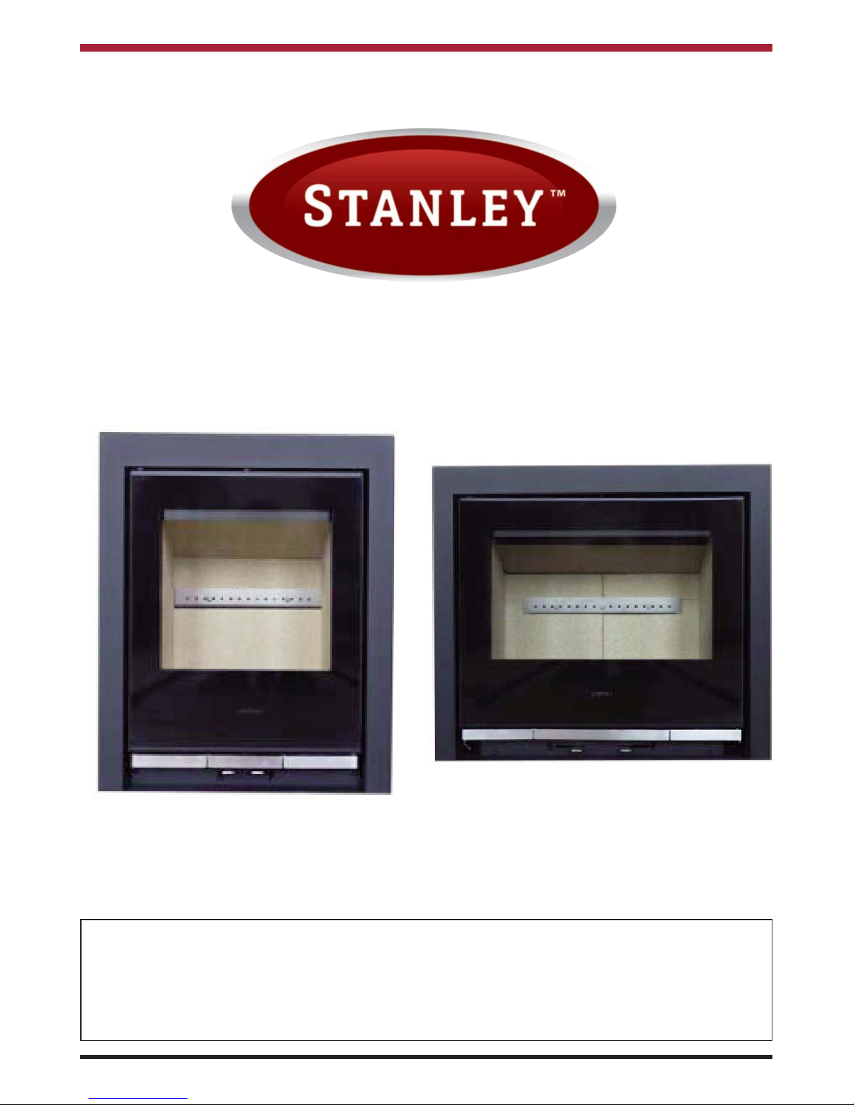
Solis Inset 500 & 900
INSTALLATION AND OPERATING INSTRUCTIONS
This appliance is hot while in operation and retains its heat for a long period of time after use. Children,
aged or infirm persons should be supervised at all times and should not be allowed to touch the hot
working surfaces while in use or until the appliance has thoroughly cooled.
When using the stove in situations where children, aged and/or infirm persons are present a fireguard
must be used to prevent accidental contact with the stove. The fireguard should be
manufactured in accordance with BS 8423:2010.
PLEASE RETAIN
Page 2

TABLE OF CONTENTS
PAGE NO.
1. Stanley Stove Warranty . . . . . . . . . . . . . . . . . . . . . . . . . . . . . . . . . . . . . . . . . . . . . . . . . . . . . . . . . . . 4
2. Installation Checklist . . . . . . . . . . . . . . . . . . . . . . . . . . . . . . . . . . . . . . . . . . . . . . . . . . . . . . . . . . . . . 5
3. Important Operation/ Maintenance Notes . . . . . . . . . . . . . . . . . . . . . . . . . . . . . . . . . . . . . . . . . . . .6
4. Installation & Operating Instructions . . . . . . . . . . . . . . . . . . . . . . . . . . . . . . . . . . . . . . . . . . . . . . . . . 7
5. General . . . . . . . . . . . . . . . . . . . . . . . . . . . . . . . . . . . . . . . . . . . . . . . . . . . . . . . . . . . . . . . . . . . . . . . 7
6. The Clean Air Act 1993 & Smoke Control Areas . . . . . . . . . . . . . . . . . . . . . . . . . . . . . . . . . . . . . . . 7
6. Flues . . . . . . . . . . . . . . . . . . . . . . . . . . . . . . . . . . . . . . . . . . . . . . . . . . . . . . . . . . . . . . . . . . . . . . . . . 8
7. Chimney . . . . . . . . . . . . . . . . . . . . . . . . . . . . . . . . . . . . . . . . . . . . . . . . . . . . . . . . . . . . . . . . . . . . . . 8
8. Fitting Instructions . . . . . . . . . . . . . . . . . . . . . . . . . . . . . . . . . . . . . . . . . . . . . . . . . . . . . . . . . . . . . . . 8
9. Flue Lined Chimney . . . . . . . . . . . . . . . . . . . . . . . . . . . . . . . . . . . . . . . . . . . . . . . . . . . . . . . . . . . . . 8
10. Non Flue Lined Chimney . . . . . . . . . . . . . . . . . . . . . . . . . . . . . . . . . . . . . . . . . . . . . . . . . . . . . . . . . 10
11. Down Draughts . . . . . . . . . . . . . . . . . . . . . . . . . . . . . . . . . . . . . . . . . . . . . . . . . . . . . . . . . . . . . . . . . 11
12. Ventilation & Combustion Air Requirements . . . . . . . . . . . . . . . . . . . . . . . . . . . . . . . . . . . . . . . . . . . 11
13. External Ducted Air . . . . . . . . . . . . . . . . . . . . . . . . . . . . . . . . . . . . . . . . . . . . . . . . . . . . . . . . . . . . . . 12
14. Heat Recovery Ventilation (HRV) . . . . . . . . . . . . . . . . . . . . . . . . . . . . . . . . . . . . . . . . . . . . . . . . . . . 13
15. Location . . . . . . . . . . . . . . . . . . . . . . . . . . . . . . . . . . . . . . . . . . . . . . . . . . . . . . . . . . . . . . . . . . . . . . . 13
16. Clearance To Combustibles . . . . . . . . . . . . . . . . . . . . . . . . . . . . . . . . . . . . . . . . . . . . . . . . . . . . . . . 13
17. Technical Data . . . . . . . . . . . . . . . . . . . . . . . . . . . . . . . . . . . . . . . . . . . . . . . . . . . . . . . . . . . . . . . . . . 14
18. Floor Protection . . . . . . . . . . . . . . . . . . . . . . . . . . . . . . . . . . . . . . . . . . . . . . . . . . . . . . . . . . . . . . . . . 15
19. Stove Dimensions 500 Model . . . . . . . . . . . . . . . . . . . . . . . . . . . . . . . . . . . . . . . . . . . . . . . . . . . . . . 16
20. Stove Dimensions 900 Model . . . . . . . . . . . . . . . . . . . . . . . . . . . . . . . . . . . . . . . . . . . . . . . . . . . . . . 17
21. Commissioning and Handover . . . . . . . . . . . . . . . . . . . . . . . . . . . . . . . . . . . . . . . . . . . . . . . . . . . . . 18
22. Operation . . . . . . . . . . . . . . . . . . . . . . . . . . . . . . . . . . . . . . . . . . . . . . . . . . . . . . . . . . . . . . . . . . . . . . 18
23. Air Controls . . . . . . . . . . . . . . . . . . . . . . . . . . . . . . . . . . . . . . . . . . . . . . . . . . . . . . . . . . . . . . . . . . . . 18
24. Recommended Fuels . . . . . . . . . . . . . . . . . . . . . . . . . . . . . . . . . . . . . . . . . . . . . . . . . . . . . . . . . . . . 18
25. Technical Data . . . . . . . . . . . . . . . . . . . . . . . . . . . . . . . . . . . . . . . . . . . . . . . . . . . . . . . . . . . . . . . . . . 19
26. Lighting . . . . . . . . . . . . . . . . . . . . . . . . . . . . . . . . . . . . . . . . . . . . . . . . . . . . . . . . . . . . . . . . . . . . . . . 19
27. Installing the Solid Fuel Kit - 500 & 900 Models . . . . . . . . . . . . . . . . . . . . . . . . . . . . . . . . . . . . . . . . 20
28. Lighting The Stove . . . . . . . . . . . . . . . . . . . . . . . . . . . . . . . . . . . . . . . . . . . . . . . . . . . . . . . . . . . . . . 20
29. Air Controls . . . . . . . . . . . . . . . . . . . . . . . . . . . . . . . . . . . . . . . . . . . . . . . . . . . . . . . . . . . . . . . . . . . . 21
30. Refuelling . . . . . . . . . . . . . . . . . . . . . . . . . . . . . . . . . . . . . . . . . . . . . . . . . . . . . . . . . . . . . . . . . . . . . 21
30. Operation With Door Left Open . . . . . . . . . . . . . . . . . . . . . . . . . . . . . . . . . . . . . . . . . . . . . . . . . . . . 21
30. Dampers Left Open . . . . . . . . . . . . . . . . . . . . . . . . . . . . . . . . . . . . . . . . . . . . . . . . . . . . . . . . . . . . . . 21
31. Slow Burning . . . . . . . . . . . . . . . . . . . . . . . . . . . . . . . . . . . . . . . . . . . . . . . . . . . . . . . . . . . . . . . . . . . 21
32. Disposal of Ashes . . . . . . . . . . . . . . . . . . . . . . . . . . . . . . . . . . . . . . . . . . . . . . . . . . . . . . . . . . . . . . . 21
33. Monthly Maintenance . . . . . . . . . . . . . . . . . . . . . . . . . . . . . . . . . . . . . . . . . . . . . . . . . . . . . . . . . . . . 21
34. Chimney Cleaning . . . . . . . . . . . . . . . . . . . . . . . . . . . . . . . . . . . . . . . . . . . . . . . . . . . . . . . . . . . . . . 22
35. Glass Cleaning . . . . . . . . . . . . . . . . . . . . . . . . . . . . . . . . . . . . . . . . . . . . . . . . . . . . . . . . . . . . . . . . . 22
36. Cleaning a Matt Black/ Senotherm Stove . . . . . . . . . . . . . . . . . . . . . . . . . . . . . . . . . . . . . . . . . . . . . 22
37. Prolonged Periods of Non Use . . . . . . . . . . . . . . . . . . . . . . . . . . . . . . . . . . . . . . . . . . . . . . . . . . . . . 22
2
Page 3

3
TABLE OF CONTENTS
PAGE NO.
38. Fire Safety . . . . . . . . . . . . . . . . . . . . . . . . . . . . . . . . . . . . . . . . . . . . . . . . . . . . . . . . . . . . . . . . . . . . . 22
39. Glass Replacement . . . . . . . . . . . . . . . . . . . . . . . . . . . . . . . . . . . . . . . . . . . . . . . . . . . . . . . . . . . . . . 23
40. CO Alarm . . . . . . . . . . . . . . . . . . . . . . . . . . . . . . . . . . . . . . . . . . . . . . . . . . . . . . . . . . . . . . . . . . . . . . 23
41. Exploded View 500 Model . . . . . . . . . . . . . . . . . . . . . . . . . . . . . . . . . . . . . . . . . . . . . . . . . . . . . . . . 24
42. Exploded View 900 Model . . . . . . . . . . . . . . . . . . . . . . . . . . . . . . . . . . . . . . . . . . . . . . . . . . . . . . . . 25
Page 4
4
STANLEY STOVE WARRANTY
CONDITIONS OF WARRANTY
Your Stanley Stove is guaranteed against any part that fails (under normal operating conditions) as detailed in the following table with timelines specified from the date of installation of the appliance. If the unit is not installed within six
months of date of purchase, the warranty will commence six months from the date of purchase.
Warranty Period Parts Covered (Parts & Labour unless Stated)
Up to 1 Year • Refractory materials (supply only)
• Rope seals, glass seals and cement seals.
• Surface Finish on Seno models.
• Grates and fire bars.
• Ceramic glass is covered for Thermal breakage (supply only).
• Rust (if reported before installation)
• Aesthetic Damage (provided reported on date of receipt)
Up to 5 Years • All external castings (excluding impact damage or damage caused by
overfiring). Pictures of damage must be submitted to WS Service
Department.
All warranty claims must be reported to the Waterford Stanley Service Department and must be submitted with the product serial number (located on the rating plate on the back of the firedoor), date of purchase, proof of purchase (if
requested) and details of the specific nature of the problem.
The warranty is given only to the original consumer/purchaser only and is non- transferable. The appliance must be
installed by a suitable qualified person and installed as per the requirements of the manual. Failure to comply with the
Installation requirements or Building Regulations will void your warranty. Waterford Stanley reserve the right to replace
any part due to manufacturing defect that fails within the warranty period under the terms of the warranty. The unit must
be used for normal domestic purposes only and in accordance with manufacturer's operation instructions.
LIMITS OF LIABILITY
The warranty does not cover:
* Special, incidental or consequential damages, injury to persons or Property, or any other consequential loss.
* Any issue caused by negligence, misuse, abuse or circumstances beyond Waterford Stanley’s control.
* Any issue with wear and tear, modification, alteration, or servicing by anyone other than an authorized service
engineer.
* Installation and operational related problems such as draught related issues external to the stove, inadequate
venting or ventilation, excessive flue offsets, negative air pressure caused by insufficient burning of improper
fuel.
* Damage caused to the unit while in transit.
* Stress fractures on bricks.
* Rust on cast iron parts unless reported prior to unit being installed.
* Aesthetic damage, rust & missing parts on units purchased off display.
Note: Adequate clearance must be maintained around the appliance to ensure the ease of part removal in the possible event of their damage/failure. Waterford Stanley are not responsible for any costs incurred in the removal of items
installed in the vicinity of the appliance that have to be moved to facilitate a part replacement.
Page 5
INSTALLATION CHECK LIST
Flue System
1. Minimum Flue Height of 4.6 metres (15 feet).
2. Appliance should be connected to a 125mm (5”) flue pipe within a metre and then
the flue size increased to a minimum of 150mm (6”) diameter (500 Models).
2A. Appliance should be connected to a 1.8m (6 feet) of 150mm (6”) flue pipe (900 Models).
3. The horizontal flue run should not exceed 150mm (6”)
4. All flue pipework passing through walls must be sleeved & adequately insulated in line
with current Building Regulations.
5. Appliance should be connected to a chimney of less than 200mm (8”) in diameter
(otherwise the chimney must be lined with a 6” flue liner).
6. The chimney/ flue termination must be located in accordance with building regulations part J.
7. The chimney serving this appliance should not serve any other appliance.
8. Access should be provided to the chimney serving the appliance to allow for cleaning. (This
can be done through the stove).
9. It is a requirement by Building Regulations to have a carbon monoxide alarm
fitted to any room with a solid fuel appliance.
Location
10. Clearance to combustible materials must be adhered to as described in the Clearance
to Combustible section.
11. The stove must be installed in a solid non combustible recess with a hearth or suitable non
combustible floor protector that extends 225mm to the front of the appliance and 150mm to
either side.
12. Clearance must be maintained to allow for maintenance and part replacement.
Ventilation & Combustion Air Requirements
13. The room in which the appliance is located should have an air vent of adequate size to
support correct combustion (see Ventilation & Combustion Air Requirement Section for
specific details).
14. The stove must not be installed in the same room as an extractor fan.
Tick
5
Page 6
IMPORTANT OPERATION / MAINTENANCE NOTES
Now that your Stanley Stove is installed and no doubt you are looking forward to many comforts it will provide,
we would like to give you some tips on how to get the best results from your stove.
1. We would like if you could take some time to read the operating instructions/hints, which we are
confident, will be of great benefit to you.
2. Do not burn fuel with a high moisture content, such as a damp peat or unseasoned timber. This will
only result in a build up of tar in the stove and in the chimney.
3. IMPORTANT: The first few fires should be relatively small to permit the refractory to set properly and
season the stove. During these firings it is recommended to ventilate the room as an unpleasant
(not toxic) odour may be emitted as the paint is completing curement.
LEAVE THE DOOR SLIGHTLY AJAR DURING THE FIRST FIRING TO PREVENT THE ROPE FROM STICKING TO THE PAINT DURING THE CURING PROCESS.
4. Inspect the flue-ways of the stove weekly and ensure that there are no blockages. Check flue
ways before lighting especially after a shut down period. Please see chimney cleaning section.
5. Before loading fresh fuel into the firebox, riddle fully to remove all ashes. This will allow better and
cleaner burning. See Re-Fuelling section.
6. Never allow a build up of ashes in the ash pan, as this will cause the grate to burn out prematurely.
Empty the ashpan when refuelling.
7. Avoid slow burning of damp or unseasoned fuel as this will result in tarring flue ways and chimney i.e. peat or timber.
8. Allow adequate air ventilation to ensure plenty of air for combustion.
9. Do not burn rubbish/household plastic.
10. Clean the chimney at least twice a year.
11. Burning soft fuels such as timber and peat will stain the glass. Regular cleaning will prevent
permanent staining. Clean with soapy water when cool.
12. Keep all combustible materials a safe distance away from unit, please see section for clearances
to combustibles.
13. Never use aerosol spray near the appliance when it is in operation.
14. For safety reasons never leave children or the elderly unaccompanied while stove is in use. Use a
fire guard.
15. Avoid contact with the appliance when in use as stove reaches very high operating temperatures.
16. This appliance should be regularly maintained by a competent service engineer.
FUEL CALORIFIC VALUES - SOLID FUELS
Anthracite 25-50mm C.V.: 8.2kW/Kg 14,000 BTUs/lb
House Coal 25-75mm C.V.: 7.2kW/Kg 12,000 BTUs/lb
Timber - Firebox size C.V.: 5.0kW/Kg 8,600 BTUs/lb
Peat Briquettes C.V.: 4.8kW/Kg 8,300 BTUs/lb
6
Page 7

7
INSTALLATION & OPERATING INSTRUCTIONS
GENERAL
THE CLEAN AIR ACT 1993 AND SMOKE
CONTROL AREAS
Under the Clean Air Act local authorities may
declare the whole or part of the district of the authority to be a smoke control area. It is an offence to emit
smoke from a chimney of a building, from a furnace
or from any fixed boiler if located in a designated
smoke control area. It is also an offence to acquire
an "unauthorised fuel" for use within a smoke control
area unless it is used in an "exempt" appliance
("exempted" from the controls which generally apply
in the smoke control area).
In England appliances are exempted by publication
on a list by the Secretary of State in accordance with
changes made to sections 20 and 21 of the Clean
Air Act 1993 by section 15 of the Deregulation Act
2015. Similarly in Scotland appliances are exempted by publication on a list by Scottish Ministers
under section 50 of the Regulatory Reform
(Scotland) Act 2014.
In Northern Ireland appliances are exempted by
publication on a list by the Department of
Agriculture, Environment and Rural Affairs under
Section 16 of the Environmental Better regulation
Act (Northern Ireland) 2016.
In Wales appliances are exempted by regulations
made by Welsh Ministers.
Further information on the requirements of the
Clean Air Act can be found here:
https://www.gov.uk/smoke-control-area-rules
Your local authority is responsible for implementing
the Clean Air Act 1993 including designation and
supervision of smoke control areas and you can
contact them for details of Clean Air Act requirements.
The Solis 500 and 900 stoves have been recommended as suitable for use in smoke control areas
when burning wood logs.
When installing, operating and maintaining your
Solis Inset respect basic standards of fire safety.
Read these instructions carefully before commencing the installation. Failure to do so may result in
damage to persons and property. Consult your local
Municipal office and your insurance representative
to determine what regulations are in force. Save
these instructions for future reference.
Please note that it is a legal requirement under
England & Wales Building Regulations that the
installation of the stove is either carried out under
Local Authority Building Control approval or is
installed by a Competent Person registered with a
Government approved Competent Persons
Scheme. HETAS Ltd operate such a scheme and a
listing of their Registered Competent Persons can
be found on their website at www.hetas.co.uk.
Special care must be taken when installing the stove
such that the requirements of the Health & Safety at
Work Act are met.
Handling
Adequate facilities must be available for loading,
unloading and site handling.
Fire Cement
Some types of fire cement are caustic and should
not be allowed to come into contact with the skin. In
case of contact with the skin wash immediately with
plenty of water.
Asbestos
This stove contains no asbestos. If there is a possibility of disturbing any asbestos in the course of
installation then please seek specialist guidance and
use appropriate protective equipment.
Metal Parts
When installing or servicing this stove care should
be taken to avoid the possibility of personal injury.
“IMPORTANT WARNING”
This stove must not be installed into a chimney that
serves any other heating appliance.
The complete installation must be done in accordance with current Standards and Local Codes. It
should be noted that the requirements and these
publications may be superseded during the life of
this manual.
Please refer to the current standards, BS EN 152871:2007 Design, Installation and Commissioning of
chimneys. BS EN 14336:2004: Heating Systems in
Buildings. Installation & Commissioning of Water
Based Heating Systems. BS EN 12828: 2003;
Heating Systems in Buildings. Design of Water
Based Heating Systems. BS EN 12831: 2003;
Heating Systems in Buildings. method for
calculation of the design heat load.
Page 8
8
Your Solis Inset stove is supplied with the following
items:
• Ashpan
• Glove
• OSA Connection
FLUES
Flues should be vertical wherever possible and
where a bend is necessary, it should not make an
angle of more than 45
o
with the vertical. Horizontal
flue runs should be avoided in order to minimise flue
resistance and to make sweeping easier it is recommended to use 2 x 45
o
bends rather than a 90
o
bend.
CHIMNEY
Do not connect to a chimney serving another
appliance.
The stove is a radiant room heater and must be connected to a chimney of the proper size and type.
The chimney must have a cross-sectional area of at
least 30 square inches 19350sq. mm or a diameter
of at least 6” (150mm). It is best to connect to a
chimney of the same size, as connection to a larger
size may result in a somewhat less draught.
A flue that has proved to be unsatisfactory, particularly with regard to down draught should not be used
for venting this appliance until it has been examined
and any faults corrected. An existing masonry chimney should be inspected and if necessary repaired
by a competent mason or relined using an approved
lining system.
The stove must be connected to a chimney with a
minimum continuous draught of 0.06 w.g. Poor
draught conditions will result in poor performance.
All register plates, restrictor plates, damper etc.,
which could obstruct the flue at a future date should
be removed before connecting this appliance.
If connecting to an existing chimney with a flue
diameter of more that 8” it is recommend to line the
flue using a suitable stainless steel flue liner.
Where a masonry chimney is not available a proprietary type of 6”/150mm - twin wall, fully insulated
pipe may be used.
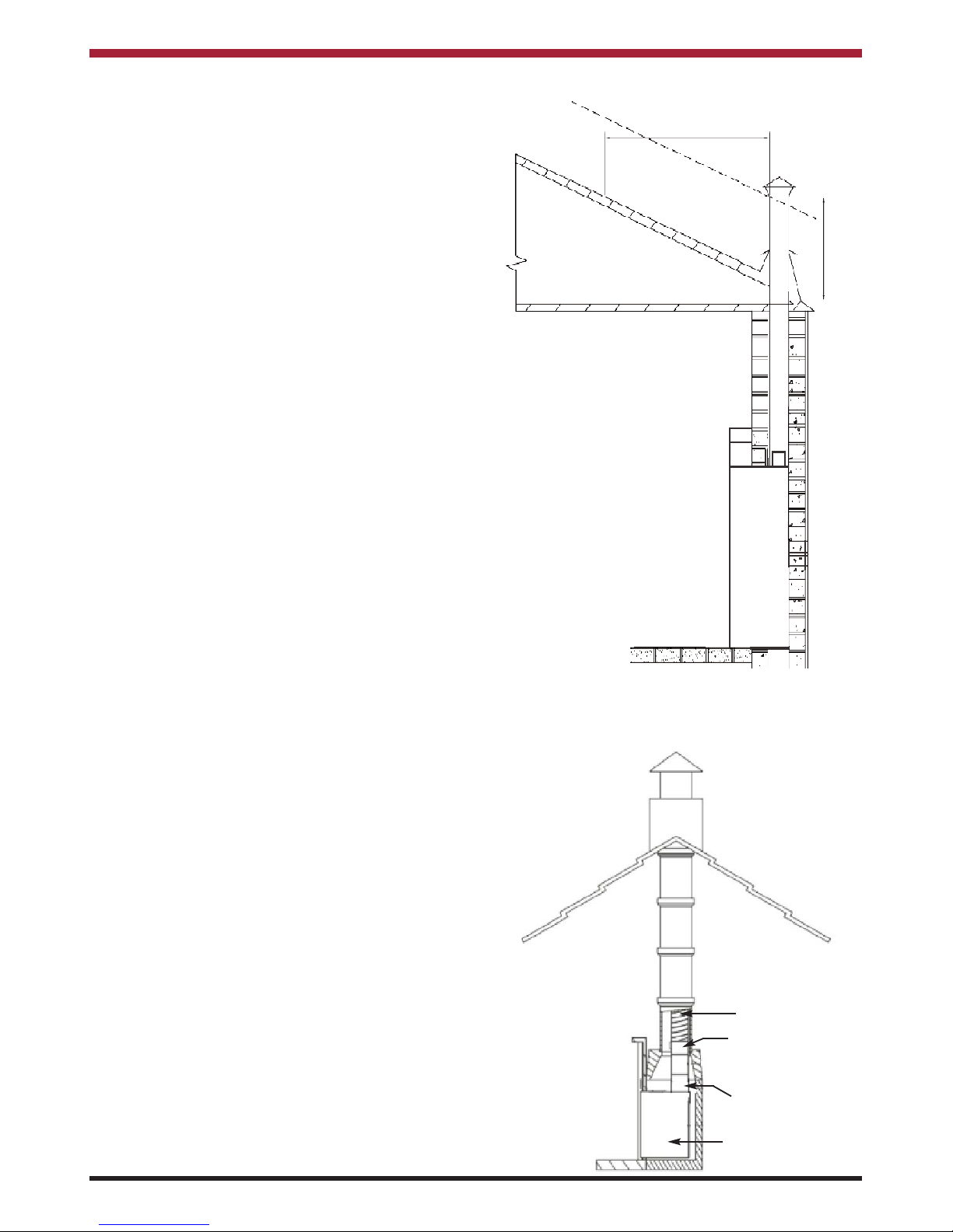
A chimney / flue termination must be located to minimise wind effects, a basic guide is that the distance
from the termination to the roof should be at least
2300mm when measured horizontally and at least
1000mm when measured vertically, (see Fig.1). In
circumstances where there are adjoining buildings/
structures/ roof openings there are additional
requirements, please refer to building regulations
part J.
Fig.1
2300
1000
FITTING INSTRUCTIONS
FLUE LINED CHIMNEY (See fig. 2)
Fig.2
Flexi Liner
Adaptor 6” flexi to
extension pipe
Extension Pipe
Inset Stove
Page 9
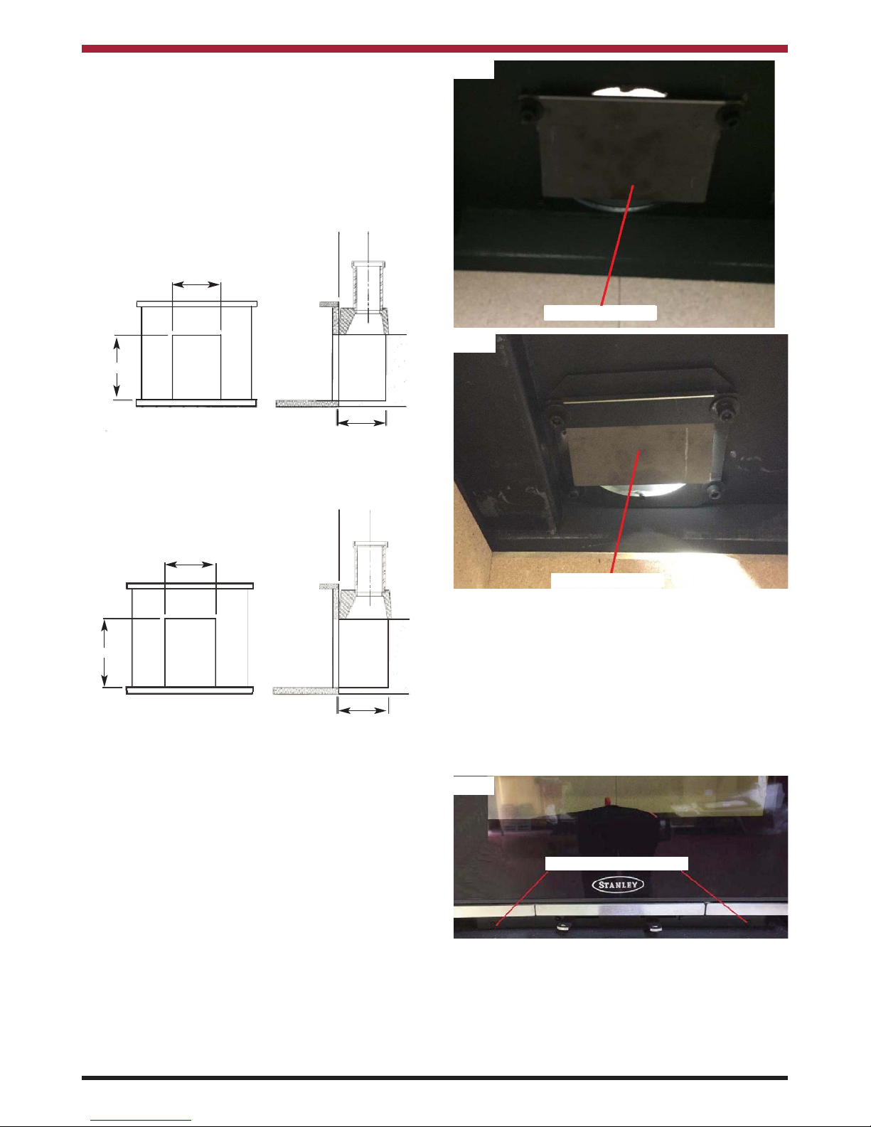
1. Ensure that the opening is suitable for fitting
of the inset stove (Fig 3 shows 500 Model &
Fig 4 shows 900 Model).
2. Ensure that the floor area is level.
3. Remove the top baffle from the firebox by
pulling it forward and lifting it up on the RHS
to allow the LHS of the baffle to drop into the
firebox so that it can be removed through the
fire door opening.
9
Fig.3 - Required opening Solis 500
* Can be reduced to 375mm if OSA connection is
not fitted.
555-585
405-450
* Min 450mm
Fig.4 - Required opening Solis 900
595-640
* Min 450mm
555-585
* Can be reduced to 375mm if OSA connection is
not fitted.
4. For the 500 model, remove the Flue
Restrictor Plate by pulling it towards the fire
door (see Figure 5) and for the 900 model,
loosen the two front spigot fixing bolts (see
Figure 6).
Fig.5
5. Remove the Flue Spigot by removing the
four M8 Allen Screws and washers.
6. Remove the Firebox Shell from the outer
casing by loosening the two M6 Allen Head
Screws and washers as shown in Figure 7
and pull the shell out from the casing.
7. Drop the flue liner down the chimney into the
fireplace and fit the flexi flue adaptor and
length of rigid pipe as required by flexible flue
manufactured to the end of the flue liner.
Fig.7
Firebox Shell Fixing Screws
Flue Restrictor Plate
Fig.6
Flue Restrictor Plate
8. Place the outer casing temporarily into its
final position to determine what length of
extension pipe is required between the adaptor & flue spigot. Cut the extension pipe to
the required length.
Page 10

10
9. Connect the extension pipe to the adaptor
and seal the joint using the appropriate fire
cement.
10. Fit the flue spigot to the extension pipe and
seal the joint using the appropriate fire
cement.
11. Position the outer casing into the fireplace
opening so that the front lip on the casing
sits against the front of the opening.
12. Mark the fixing hole locations in the base of
the outer casing and fix in place using a suitable concrete screw anchor.
13. Lift the firebox shell approximately 75mm
into the outer casing so that it can then be
pushed into the final position while taking
care to lift the front edge so that it doesn’t
damage the hearth.
14. Secure the flue spigot to the firebox shell and
secure the firebox shell to the outer casing.
15. Refit the Flue Restrictor Plate and refit the
top baffle.
16. Fit the frame by inserting the bottom lip on
the frame under the air control levers and
engaging the cut-outs on the back of the
frame into the fixing points on the shell using
the M6 screws (see Fig. 8)
Fig.8
Fixing Screws
Fig.9
NON FLUE LINED CHIMNEY (See Fig. 9)
1. Ensure that the opening is suitable for fitting
of the inset stove (Fig 3 shows 500 Model &
Fig 4 shows 900 Model).
2. Ensure that the floor area is level.
3. Remove the top baffle from the firebox by
pulling it forward and lifting it up on the RHS
to allow the LHS of the baffle to drop into
the firebox so that it can be removed through
the fire door opening.
4. For the 500 model, remove the Flue
Restrictor Plate by pulling it towards the fire
door (see Figure 5) and for the 900 model,
loosen the two front spigot fixing bolts (see
Figure 6).
5. Remove the Flue Spigot by removing the
four M8 Allen Screws and washers.
6. Remove the Firebox Shell from the outer
casing by loosening the two M6 Allen Head
Screws and washers as shown in Figure 7
and pull the shell out from the casing.
7. Fit a clay pot adaptor to the clay liner
ensuring that it is sealed using the
appropriate fire cement. Before sealing the
adaptor in position it may be best to fit the
outer casing into position so as to ensure
that the clay pot adaptor and flue spigot are
all in line and to determine what length of
extension pipe is required between the
adaptor & flue spigot.
8. Connect the extension pipe to the adaptor
and seal the joint using the appropriate fire
cement.
Page 11

11
9. Fit the flue spigot to the extension pipe and
seal the joint using the appropriate fire
cement.
10. Position the outer casing into the fireplace
opening so that the front lip on the casing
sits against the front of the opening.
11. Mark the fixing hole locations in the base of
the outer casing and fix in place using a suitable concrete screw anchor.
12. Lift the firebox shell approximately 75mm
into the outer casing so that it can then be
pushed into the final position while taking
care to lift the front edge so that it doesn’t
damage the hearth.
13. Secure the flue spigot to the firebox shell
and secure the firebox shell to the outer
casing.
14. Refit the Flue Restrictor Plate and refit the
top baffle.
15. Fit the frame by inserting the bottom lip on
the frame under the air control levers and
engaging the cut-outs on the back of the
frame into the fixing points on the shell.
16. Secure the frame to the shell using the M6
screws (see Fig. 8).
DOWN DRAUGHTS
However well designed constructed and positioned,
the satisfactory performance of the flue can be
adversely affected by down draught caused by nearby hills, adjacent tall buildings or trees. These can
deflect wind to blow directly down the flue or create
a zone of low pressure over the terminal.
A suitable terminal or cowl will usually effectively
combat direct down blow but no cowl is likely to prevent down draught due to a low pressure zone.
(See Fig.10).
Direction of wind
Pressure zone
Direction of wind
Suction zone
Pressure zone
Direction of wind
Pressure zone
Suction zone
Suction zone
Fig.10
VENTILATION & COMBUSTION AIR REQUIREMENTS
It is imperative that there is sufficient air supply to
the stove in order to support correct combustion.
The air supply to this appliance must comply with
current Building Regulations Part J, Heat Providing
Appliances. If another appliance is fitted in an adjacent room it will be necessary to calculate an additional air supply.
The minimum effective air requirement for 500
model is 5cm² and for the 900 model is 22cm².
When calculating combustion air requirements for
this appliance use the following equation:
550mm² per each kw of rated output above 5kw
should be provided, where a flue draught stabiliser is
used the total free area shall be increased by
300mm² for each kw of rated output.
Note:
There must not be an extractor fan fitted in the same
room as the stove as this can cause the stove to
emit smoke and fumes into the room.
All materials used in the manufacture of air vents
should be such that the vent is dimensionally stable,
corrosion resistant, and no provision for closure.
Page 12

12
The effective free area of any vent should be ascertained before installation. The effect of any grills
should be allowed for when determining the effective
free area of any vent.
Air vents should be positioned so that they are not
liable to blockage.
Air vents direct to the outside of the building should
be located so that any air current produced will not
pass through normally occupied areas of the room.
An air vent outside the building should not be located less than the dimensions specified within the
Building Regulations and B.S. 8303: Part 1 from any
part of any flue terminal. These air vents must also
be satisfactorily fire proofed as per Building
Regulations and B.S. 8303: Part 1.
Air vents in internal walls should not communicate
with bedrooms, bedsits, toilets, bathrooms or rooms
containing a shower.
Air vents traversing cavity walls should include a
continuous duct across the cavity. The duct should
be installed in such a manner as not to impair the
weather resistance of the cavity.
Joints between air vents and outside walls should be
sealed to prevent the ingress of moisture. Existing
air vents should be of the correct size and unobstructed for the appliance in use.
If there is an extraction fan fitted in adjacent rooms
where this appliance is fitted, additional air vents
may be required to alleviate the possibility of
spillage of products of combustion from the appliance/flue while the fan is in operation. Refer to B.S.
8303 Part 1.
Where such an installation exists, a test for spillage
should be made with the fan or fans and other appliances using air in operation at full rate, (i.e.extraction fans, tumble dryers) with all external doors and
windows closed.
If spillage occurs following the above operation, an
additional air vent of sufficient size to prevent this
occurrence should be installed.
Especially Airtight Properties:-
If the stove is being fitted in a property where the
design air permeability is less than 5m
3
/ (h.m2) (normally newer properties built from 2006), then a permanent ventilation must be fitted to provide 550mm
2
of ventilation for each kW of rated output. If a
draught stabiliser is also fitted then the requirement
is 850mm
2
per kW of rated output.
EXTERNAL DUCTED AIR
Where required the primary air supply can be ducted from outside.
It is recommended to bring the air supply for the
stove into the house using a 4” plastic pipe. Where
the pipe meets the outside wall make sure a vent
cover is fitted properly to ensure no rodents can
enter via the vent pipe.
The vent pipe should be located to prevent the
ingress of moisture and in a location where it will not
get blocked with leaves or any other debris. As wind
effects can create suction and pressure zones of
opposite sides of the dwelling it is recommended to
run the air vent from opposite poles (North, South,
East & West) of the dwelling and tee off for the air
supply to the stove. This should negate the effect
of suction and pressure zones. See Fig. 11
‘HETAS product approval covers this appliance
when installed in accordance with the manufacturer’s instructions and relevant standards. As there is
currently no standard for Ducted Combustion Air
Supply this does not fall within the remit for HETAS
product approval. Responsibility for the specification
of this and for appropriate manufacturer’s instructions is carried by the appliance manufacturer, as
allowed for under the Building Regulations.’
Page 13

13
Note: When Installing
outside air pipe adhere
to ‘Clearance to
Combustible’ Section.
Fig.11
4” ID ALUMINIUM
FLEXIBLE DUCT
PIPE ENDS TO BE
COVERED WITH MESH
4” OD CONNECTOR SADDLE
HEAT RECOVERY VENTILATION
Where a stove is to be installed in a dwelling with
Heat Recovery Ventilation (HRV) a number of precautionary measures must be undertaken:
Where the product is to be installed with a
Mechanical ventilation, the stove must be connected
to an external air supply, The ductwork for the external air supply must be no longer than 6 metres and
the air inlet terminal to the ductwork must have a
cross sectional area of at least 80cm2.
LOCATION
There are several conditions to be considered in
selecting a location for your Solis Inset.
a. Position in the area to be heated, central
locations are usually best.
b. Allowances for proper clearances to
combustibles.
c. Allowances for proper clearances for mainte-
nance work.
Clearances to Combustibles
This appliance must be installed in a recess, the
recess should not contain any combustible material.
Wood battens and plaster board should not be used
within the clearance to combustibles. The minimum
clearance to combustibles required is as follows:
500
Model
900
Model
To p A 550mm 550mm
Sides B 250mm 250mm
Front C 800mm 1200mm
Combustible Flooring Front
D 225mm 225mm
Combustible Flooring Side
- 150mm 150mm
Back - 100mm 100mm
Fig.12
A
B B
Page 14

14
Fig.13
C
D
If the appliance recess is close to any combustible
material, it must be adequately protected using a
suitable insulation material (See table 1) and configured as showing in Fig. 14.
MATERIAL DESCRIPTION
SILCA 250KM
Approval in Germany
National technical approval no Z-43.14-117 valid for
fireplace and tiled stove construction
Approval in Switzerland Fire Prevention Approval no. 15202
Fire resistance DIN EN 13501-2 El 120 (8O mm)
CE-Certificate
0432-CPD-420002242/2-6
Construction material class DIN 4102 Non-combustible A1
Bulk density (± 10 %) DIN EN 1094-4 250 kg/m3
Porosity DIN EN 1094-4
Approx. 90 %
Compressive strength DIN EN 1094-5 > 1.4 MPa
Thermal conductivity at 200 °C DIN EN 993-14 <0.1 W/mK
Thermal expansion at 500 °C DIN EN 993-8
< 0.2 %
Standard dimensions in mm 3,000 x 1,250, 1,250 x 1,000; 1,250 x 500; 1,000 x
625; 625 x 500
Standard thicknesses in mm 30-100
TECHNICAL DATA
Page 15

15
The insulation material must be at least 120mm in
thickness and must be situated at least 100mm
away from the rear and sides of the appliance.
Fig.14
Convection Air
Outlet
Combustible
Wall
12 cm
10 cm
Convection
Air Inlet
Combustible
Floor
Heat (thermal)
Insulation
FLOOR PROTECTION
It is recommended that the appliance is installed on
a solid, level, concrete base of non combustible
hearth conforming to the current Building
Regulations which must extend 225mm in front of
the unit and 150mm from the sides of the front edge.
This will provide protection from sparks and embers
which may fall out when stoking on refuelling.
Page 16

16
STOVE DIMENSIONS
490
590
100
400
500 Model
Fig.15
105
THREE SIDED FRAME
550
425
350
105
100
105
FOUR SIDED FRAME
490
645
550
425
350
100
105
Page 17

900 Model
THREE SIDED FRAME
675
590
585
95
75
425
555
95
350
85
100
FOUR SIDED FRAME
17
WARNING: DO NOT OBSTRUCT PRIMARY AIR SUPPLY TO THE STOVE
Note: Dimensions stated are in millimetres unless otherwise stated and may be subject to a slight +/- variation.
645
675
425
350
555
100
85
Page 18

COMMISSIONING AND HANDOVER
On completion of the installation allow a suitable
period of time for any fire cement and mortar to dry
out, when a small fire may be lit and checked to
ensure the smoke and fumes are taken from the
stove up the chimney and emitted safely to the
atmosphere. Do not run at full output for at least
24 hours.
Ensure that the operating instructions for the stove
are left with the customer. Ensure to advise the customer on the correct use of the appliance with the
fuels likely to be used on the stove and warn them to
use only the recommended fuels for the stove.
Advise the user what to do should smoke or fumes
be emitted from the stove. The customer should be
warned to use a fireguard to BS 8423: 2010 in the
presence of children, aged and/or infirm persons.
OPERATION
Check that all dampers and catches are operating
correctly and ensure that all flue connections are
thoroughly sealed.
AIR CONTROLS
The Solis Inset has two independent air controls
(See fig. 16)
1. The primary air control lever is the right
hand lever located under the fire door. Push
right to open and left to close.
2. The secondary air control lever is the left
hand lever located under the fire door. Push
left to open and right to close.
Secondary
Air
Primary
Air
Fig.16
RECOMMENDED FUELS
All fuels should be stored under cover and kept
as dry as possible prior to use.
This appliance has been tested using seasoned
wood logs.
If opting to burn solid fuel, a solid fuel kit must be
installed. (See Installing Solid Fuel Kit section)
Do not use fuels with a Petro-coke ingredient as this
may cause the grate to overheat, causing damage.
Reduced outputs will result when fuels of lower
calorific values are used. Never use gasoline or
gasoline type lantern fuel, kerosene, charcoal lighter
fluid or similar liquids to start or freshen up a fire in
this heater. Keep all such liquid well away from the
heater at all times. Operate the stove only with the
fuelling door closed except for re-fuelling.
This stove has obtained HETAS Ltd approval for
burning seasoned wood logs as detailed in recommended fuels below. HETAS Approval does not
cover the use of other fuels either alone or mixed
with the recommended fuels listed, nor does it cover
instructions for the use of other fuels.
18
Page 19

19
TECHNICAL DATA
MANUFACTURED
SMOKELESS FUEL WOOD
MANUFACTURED
SMOKELESS FUEL WOOD
Nominal Output: (kW) Room 5kW Room 5kW Room 9kW Room 9kW
Typical refuelling
intervals to obtain
nominal outputs:
MSF 1 hour Wood .75 hours MSF 1 hour Wood .75 hours
Mean Flue Gas
Temperature
o
C
205 253 328 296
Flue Gas Mass Flue 4.3 4.3 7 7
Flue Outlet:
Efficiency 81% 82% 75% 80%
Flue Draught:
Max Log Size N/A Ø100mm x 260 mm N/A Ø100mm x 440 mm
127 mm
152 mm
12 PA
Model
Energy
Efficiency
Class
Heat Output
to Room
Heat Output
to Water
Energy
Efficiency
Index
Preferred
Fuel
Nominal
Heat
Output Net Efficiency
Solis
Inset
500
A
+
5 N/A 110 Wood 5 82
Solis
Inset
900
A
+
9 N/A 107 Wood 9 80
LIGHTING
Before lighting the stove check with the installer that the installation work and commissioning checks described
previously have been carried out correctly and that the chimney has been swept clean, is sound and free from
any obstructions. As part of the stoves commissioning and handover the installer should demonstrate how to
operate the stove correctly.
LEAVE THE DOOR SLIGHTLY AJAR DURING THE FIRST FIRING TO PREVENT THE ROPE FROM STICKING TO THE PAINT DURING THE CURING PROCESS.
SOLIS INSET 500
SOLIS INSET 900
Page 20

LIGHTING THE STOVE
1. Open the fire door and open the primary air inlet by pushing the primary air control lever to the right.
2. Open the secondary air inlet by pushing the secondary air control lever to the left.
3. Cover the grate with crumpled pieces of paper and lay 10-12 pieces of kindling on top of the paper
towards the back of the firebox.
4. lgnite and close the fire door.
5. When the kindling is well alight open the fire door and add more kindling of a larger size
to sustain the fire. Close the fire door.
6. When a hot fire bed is established add the normal fuel.
7. When well lighted, adjust the air controls as required depending on the fuel type being used & the heat
output required (see Table). Both controls should be adjusted in conjunction with each other to
get the appropriate burn rate with exact settings on each control depending on the draught conditions
of the chimney to which the unit is connected.
8. If there is insufficient burning material in the firebed to light a new fuel charge, excessive smoke emis-
sion can occur. Refuelling must be carried out onto a sufficient quantity of glowing embers and ash that
the new fuel charge will ignite in a reasonable period. If there are too few embers in the fire bed, add
suitable kindling to prevent excessive smoke.
9. The maximum amount of fuel specified in this manual should not be exceeded, overloading can cause
excess smoke.
INSTALLING SOLID FUEL KIT - 500 MODEL
IF OPTING TO BURN SOLID FUEL, A SOLID FUEL
KIT MUST BE INSTALLED.
1. Open the firedoor and remove the ashpan.
2. Lift out the grate by pushing it upwards
through the ash compartment.
3. Remove the base bricks (see Fig. 17).
20
Fig.17
4. Refit the grate.
5. Fit the two refractory bricks as shown in fig.
19.
Fig.19
INSTALLING SOLID FUEL KIT - 900 MODEL
IF OPTING TO BURN SOLID FUEL, A SOLID FUEL
KIT MUST BE INSTALLED.
1. Open the firedoor and remove the ashpan.
2. Lift out the grate by pushing upwards
through the ash compartment.
3. Remove the two floor bricks.
4. Lay the two refractory bricks into the
firebox as shown in fig. 20.
5. Refit the grate.
Fig.20
Fig.18
Base Bricks
Refractory Bricks
Page 21

REFUELLING
Before opening the door, open the primary air control fully as this will help to eliminate any smoke or
fly ash resident in the combustion chamber. Add fuel
to fire, close fire door and re-set the air controls to
the required setting.
OPERATION WITH DOOR LEFT OPEN
Operation with the door open can cause excess
smoke. The appliance must not be operated with the
appliance door left open except as directed in the
instructions.
DAMPERS LEFT OPEN
Operation with the air controls or appliance dampers
open can cause excess smoke. The appliance must
not be operated with air controls, appliance dampers
or door left open except as directed in the instructions.
SLOW BURNING
Slow burning will cause the window glass to blacken
and should not be used for a long period. It should
only be done after the fire has been established and
been running at nominal output for a period of time.
For a prolonged slow burn, fill the firebox of fuel up
to a maximum height just below the top of the fire
fence at the front of the door opening. Close the primary air control and the secondary air control.
DISPOSAL OF ASHES
Your stove is provided with an ashpan which should
be emptied every day.
If ashes are allowed to build to grate level you could
damage the grate by overheating. We recommend
that you remove ashes after you have riddled the fire
when the stove is thoroughly cooled.
21
AIR CONTROLS
Fuel
Primary Air Secondary Air Primary Air Secondary Air
Anthracite/
Smokeless Coal
Fully Open Fully Closed 0-80% Open Fully Closed
Ignition Controlled Burn
Wood/ Turf Fully Closed Fully Open Fully Closed 0-80% Open
MONTHLY MAINTENANCE
Cleaning Stove Flue Pathways
It is recommended that the flue pathways in the
stove are cleaned on a monthly basis (or less
depending on the soot build-up created by the fuel
being used) and the chimney cleaned annually. To
access the chimney pathways, use the following
procedure:
1. Remove the top baffle from the firebox by
pulling it forward and lifting it up on the RHS
to allow the LHS of the baffle to drop into the
firebox so that it can be removed through the
firedoor opening.
2. Remove the Flue Restriction Plate by pulling
it towards the firedoor (see Fig. 21).
Fig.21
Flue Restrictor Plate
Ashes should be placed in a metal or other noncombustible container with a tight fitting lid. The
closed container of ashes should be placed on a
non-combustible material, pending final disposal. If
ashes are buried in soil, or otherwise dumped they
should be retained in the closed container until they
are thoroughly cooled.
Open the firedoor and remove the ashpan using the
glove provided. Close the firedoor. When the ash is
disposed of, replace the ashpan.
Page 22

22
CHIMNEY CLEANING
The chimney should be cleaned twice annually or if
the stove is not used for a prolonged period during
the summer period, it should be cleaned prior to
commencement of usage. The chimney can be
cleaned through the stove depending on the flue
configuration and the flue liner should be cleaned in
accordance with manufacturer's instructions. Always
use a brush with plastic bristles that is the correct
size to reach all areas of the flue.
GLASS CLEANING
The stove glass will self-clean when there is sufficient heat generated by the burning fuel i.e. when
the unit is operated at the maximum air settings. If a
build-up of creosote occurs on the glass it may be
due to low draft conditions, poor quality fuel or operating the stove at the minimum air settings for long
periods of time. The glass should be cleaned when
cool and cleaned with a non-abrasive cloth using
warm soapy water. For stubborn deposits, a grade 0
steel wool can be used whilst taking care not to
scratch the glass with any coal/ash deposits.
CLEANING A MATT BLACK/SENOTHERM
STOVE
Cleaning should be done when the stove is cold by
removing any dust or dirt using a dry cloth. Do not
use any water on the matt black/senotherm finish as
this will cause it to rust.
PROLONGED PERIODS OF NON USE
If the stove is to be left unused for a prolonged period of time then it should be given a thorough clean
to remove ash and unburned fuel residues. To
enable a good flow of air through the appliance to
reduce condensation and subsequent damage,
leave the air controls fully open.
It is important that the flue connection, any appliance
baffles or throat plates and the chimney are swept
prior to lighting up after a prolonged shutdown
period.
WARNING NOTE:
Properly installed, operated and maintained this
stove will not emit fumes into the dwelling.
Occasional fumes from the de-ashing and refuelling may occur. However, persistent fume emission is potentially dangerous and must not be tolerated. If fume emission does persist, then the following immediate action should be taken:
(a) Open doors and windows to ventilate room.
(b) Let the fire out or eject and safely dispose of
fuel from the stove.
(c) Check for flue or chimney blockage and clean if
required.
(d) Do not attempt to relight the fire until the cause
of the fume emission has been identified and
corrected. If necessary seek expert advice.
The most common cause of fume emission is flueway or chimney blockage. For you own safety these
must be kept clean at all times.
FIRE SAFETY
To provide reasonable fire safety, the following
should be given serious consideration.
1. Do not over fire the stove.
2. Over-firing will also damage painted or enamel
finish.
3. Install a smoke detector in the room.
4. A conveniently located class A fire extinguisher to
contend with small fires resulting from burning
embers.
5. A practical evacuation plan.
6. A plan to deal with a chimney fire as follows:-
(a) Notify the fire department.
(b) Prepare occupants for immediate evacua-
tion.
(c) Close all openings into the stove.
(d) While awaiting the fire department watch for
ignition to adjacent combustibles from over-
heated flue pipe or from embers or sparks
from the chimney.
Page 23

GLASS REPLACEMENT
(a) Open the firedoor fully.
(b) Remove the top glass retaining bracket by
removing the two fixing screws (see Fig. 22).
(c) Lift the glass free off the bottom retaining brack-
et.
(d) Before fitting the new glass, check the glass
sealing on the door frame and replace if necessary.
CO ALARM
The fitting of CO Alarms in the same room as the
appliance is a compulsory requirement under current Building Regulations. For ROI an additional CO
Alarm must be fitted either inside each bedroom or
within 5 metres of the bedroom door, refer to
Building Regulations Part J. Further guidance on the
installation of a carbon monoxide alarm is available
in BS EN 50292:2002 and from the alarm manufacturers instructions.
Provision of an alarm must not be considered a
substitute for either installing the appliance
correctly or ensuring regular servicing and
maintenance of the appliance and chimney
system.
WARNING:-
If the CO Alarm sounds unexpectedly:-
1. Open Doors and windows to ventilate the
room and then leave the premises.
2. Let the fire go out.
23
Fig.22
Glass Retaining Bracket Screws
Page 24

STANLEY SOLIS INSET 500 EXPLODED VIEW
24
1. GRATE - 9825001
2. DOOR LOCKING SYSTEM - 093-01-060
3. DOOR SUBASSEMBLY - 093-01-010
4. DOOR GLASS - 093-01-070
5. ASH PAN - 093-06-000
6A. THREE SIDE FRAME - 093-07-000
6B. FOUR SIDED FRAME - 093-07-000A
7. TOP BAFFLE - 093-30-006
8. AIR CONTROL CHAMBER - 093-09-000
9. FLUE SPIGOT - 093-05-040
10. OSA CONNECTION - 093-05-010
11. LH SIDE BRICK - 093-30-008
12. RH SIDE BRICK - 093-30-007
13. LH BASE BRICK - 093-30-001
14. REAR BASE BRICK - 093-30-003
15. RH BASE BRICK - 093-30-002
16. BOTTOM BACK BRICK - 093-30-004
17. TOP BACK BRICK - 093-30-005
18. BOTTOM BACK BRICK FIXING BRACKET - 093-30-009
19. CHROME DOOR TRIM - 093-01-040
20. FLUE RESTRICTOR PLATE - 093-00-005
21. FLUE RESTRICTOR PLATE FIXING BRACKET - 093-08-000
22. SPRING LOADED LOCKING MECHANISM - SET - 093-02-070
23. PRIMARY AIR CONTROL LEVER - 093-09-030
24. SECONDARY AIR CONTROL LEVER - 093-09-020
DOOR GLASS GASKET (3X25 MM) - 10001619
DOOR GASKET (Ø12 MM) - 30000248
Page 25

25
STANLEY SOLIS INSET 900 EXPLODED VIEW
1. DOOR GLASS I-G9I - 098-00-012
2. DOOR SUBASSEMBLY I-G9I - 098-01-000
3. DOOR LOCKING SYSTEM - 099-03-015
4. ASH PAN - 099-00-005
5A. THREE SIDE FRAME - F01326AXX
5B. FOUR SIDED FRAME - 093-07-000
6. GRATE - 30000328
7. TOP BAFFLE - 099-09-003
8. AIR CONTROL CHAMBER - 099-05-000
9. OSA CONNECTION - 099-06-000
10. FLUE SPIGOT - 099-06-005
11. LH SIDE BRICK - 099-09-001
12. RH SIDE BRICK - 099-09-002
13. LH BASE BRICK - 099-09-004
14. RH BASE BRICK - 099-09-004
15. LH BACK BRICK - 099-09-005
16. RH BACK BRICK - 099-09-006
17. AIR CONTROL LEVER PRIM / SET - 099-05-023
19. STAINLESS DOOR TRIM - 099-03-019
20. FLUE RESTRICTOR PLATE - 099-10-004
21. FLUE RESTRICTOR PLATE FIXING BRACKET - 099-10-002
22. SPRING LOADED LOCKING MECHANISM - SET - 099-13-000
DOOR GLASS GASKET (Ø6 MM) - 10000972
DOOR GASKET (Ø12 MM) - 30000248
Page 26

26
NOTES
Page 27

27
NOTES
Page 28

28
Manufactured by
Waterford Stanley Ltd.,
Unit 401-403, IDA Industrial Estate, Cork Road,
Waterford, Ireland.
Tel: (051) 302300 Fax (051) 302315
Rev: 005
SG 051018
 Loading...