

Page 1
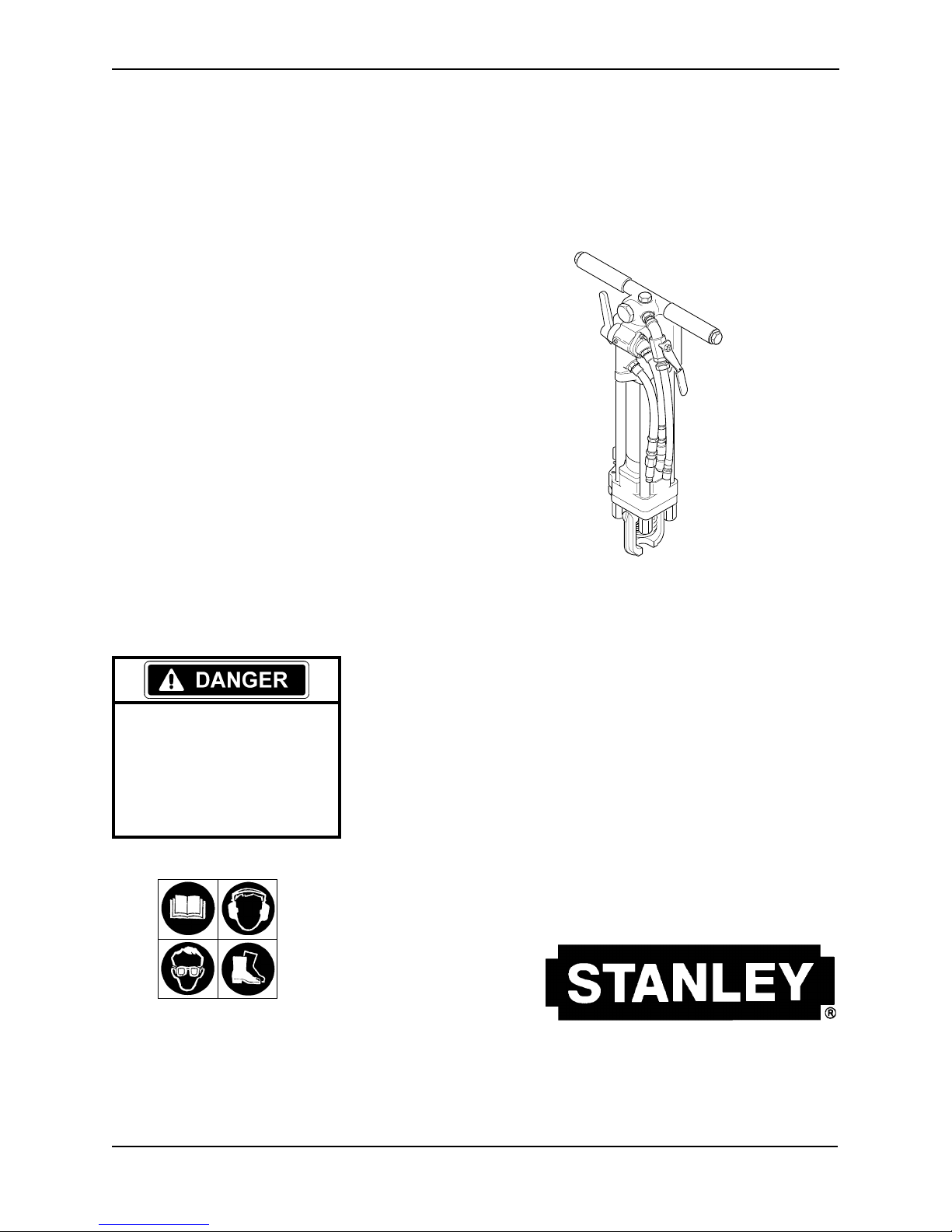
SK58
Hydraulic Sinker Drill
SERIOUS INJURY OR DEA TH COULD
RESULT FROM THE IMPROPER REPAIR OR SERVICE OF THIS T OOL.
REPAIRS AND / OR SER VICE TO THIS
TOOL MUST ONLY BE DONE BY AN
AUTHORIZED AND CERTIFIED
DEALER.
SafetySafety
Safety
SafetySafety
, Operation and Maintenance, Operation and Maintenance
, Operation and Maintenance
, Operation and Maintenance, Operation and Maintenance
Service ManualService Manual
Service Manual
Service ManualService Manual
Copyright © 1999 The Stanley WCopyright © 1999 The Stanley W
Copyright © 1999 The Stanley W
Copyright © 1999 The Stanley WCopyright © 1999 The Stanley W
OPS/MAINT USA VERSION
05449 03/99 Ver 2
orksorks
orks
orksorks
Stanley Hydraulic TStanley Hydraulic T
Stanley Hydraulic T
Stanley Hydraulic TStanley Hydraulic T
3810 SE Naef Road
Milwaukie, OR 97267-5698 USA
Phone: (503) 659-5660
Fax: (503) 652-1780
oolsools
ools
oolsools
Page 2

SAFETY FIRST
It is the responsibility of the operator
and service technician to read rules and
instructions for safe and proper
operation and maintenance.
A cautious worker
using common sense
is the greatest safety device
COPYRIGHT© 1999 The Stanley Works. All rights reserved.
Under copyright law, this document may not be copied in whole or in
part without the prior written consent of The Stanley Works. This exception does not permit copies to be made for others, whether or not sold.
Under the law, copying includes translating into another language,
format, or medium. This copyright notice must appear on any permitted
copies.
Page 3

CONTENTS
Accessories ........................................................................................................ 18
Hydraulic Hose Requirements ............................................................................. 5
Hydraulic Requirements....................................................................................... 6
Model Descriptions............................................................................................. 20
Operation ........................................................................................................ 7 - 8
Principle of Operation ............................................................................ 6
Safety Precautions .......................................................................................... 2 - 3
Service Instructions ....................................................................................... 9 - 15
Accumulator Charging ......................................................................... 15
Accumulator Housing , Accumulator, Flow Sleeve, Piston,
and Automatice Valve Service...................................................... 12 - 14
Hydraulic Motor Service................................................................ 10 - 12
Latch and Spring Service....................................................................... 9
Parts Illustration ................................................................................... 20
Parts Illustration for Anti-Vibration Handle Models .............................. 21
Parts Lists ............................................................................................ 19
Special Tools ........................................................................................ 1 8
Throttle Valve Service..................................................................... 9 - 10
Specifications ..................................................................................................... 18
Tool Stickers and Tags ......................................................................................... 4
Troubleshooting .......................................................................................... 16 - 17
Warranty............................................................................................................. 21
SERVICING THE SK58 SINKER DRILL: This manual contains safety, operation, and detailed
maintenance instructions. Stanley Hydraulic Tools recommends that servicing of hydraulic tools,
other than routine maintenance, must be performed by an authorized and certified dealer. Please
read the following warning.
SERIOUS INJURY OR DEASERIOUS INJURY OR DEA
SERIOUS INJURY OR DEA
SERIOUS INJURY OR DEASERIOUS INJURY OR DEA
IMPROPER REPIMPROPER REP
IMPROPER REP
IMPROPER REPIMPROPER REP
REPREP
AIRS AND / OR SERVICE TO THIS TOOL MUST ONLAIRS AND / OR SERVICE TO THIS TOOL MUST ONL
REP
AIRS AND / OR SERVICE TO THIS TOOL MUST ONL
REPREP
AIRS AND / OR SERVICE TO THIS TOOL MUST ONLAIRS AND / OR SERVICE TO THIS TOOL MUST ONL
BE DONE BBE DONE B
BE DONE B
BE DONE BBE DONE B
For the nearest authorized and certified dealer, call Stanley Hydraulic Tools at 1-503-659-5660 and
ask for a Customer Service Representative.
AIR OR SERVICE OF THIS TOOLAIR OR SERVICE OF THIS TOOL
AIR OR SERVICE OF THIS TOOL
AIR OR SERVICE OF THIS TOOLAIR OR SERVICE OF THIS TOOL
Y AN AY AN A
Y AN A
Y AN AY AN A
UTHORIZED AND CERTIFIED DEALERUTHORIZED AND CERTIFIED DEALER
UTHORIZED AND CERTIFIED DEALER
UTHORIZED AND CERTIFIED DEALERUTHORIZED AND CERTIFIED DEALER
TH COULD RESULTH COULD RESUL
TH COULD RESUL
TH COULD RESULTH COULD RESUL
T FROM THET FROM THE
T FROM THE
T FROM THET FROM THE
..
.
..
YY
Y
YY
..
.
..
1
Page 4

SAFETY
The SK58 Hydraulic Sinker Drill will provide safe and dependable service if
operated in accordance with the instructions given in this manual. Read and
understand this manual and any stickers and tags attached to the tool and hoses
before operation. Failure to do so could result in personal injury or equipment
damage.
Tool operators and maintenance personnel must always comply with the safety
precautions given in this manual and on the stickers and tags attached to the tool
and hose.
These safety precautions are given for your safety. Review them carefully before operating the tool and before
performing general maintenance or repairs.
Supervising personnel should develop additional precautions relating to the specific work area and local safety
regulations. If so, place the added precautions in the space provided on page 3.
SAFETY
GENERAL SAFETY PRECAUTIONS
• Operator must start in a work area without bystanders. The operator must be familiar with all prohibited work
areas such as excessive slopes and dangerous terrain conditions.
• Establish a training program for all operators to ensure safe operation.
• Do not operate the tool unless thoroughly trained or under the supervision of an instructor.
• Always wear safety equipment such as goggles, ear and head protection, and safety shoes at all times when
operating the tool.
• Know the location of buried or covered underground utilities before begining any work.
• Do not inspect or clean the tool while the hydraulic power source is connected. Accidental engagement of the
tool can cause serious injury.
• Always connect hoses to the tool hose couplers before energizing the hydraulic power source. Be sure all hose
connections are tight.
• Do not operate the tool at oil temperatures above 140°F/60°C. Operation at higher oil temperatures can cause
higher than normal temperatures at the tool which can result in operator discomfort.
• Do not operate a damaged, improperly adjusted, or incompletely assembled breaker.
• Do not weld, cut with an acetylene torch, or hard face the drill bit.
• To avoid personal injury or equipment damage, all tool repair, maintenance and service must only be performed
by authorized and properly trained personnel.
2
Page 5

SAFETY Continued . . .
• Always replace parts with replacement parts recommended by Stanley Hydraulic T ools.
• Check fastener tightness often and before each use daily.
SAFETY SYMBOLS
Safety symbols are used to emphasize all operator, maintenance and repair actions which, if not strictly followed,
could result in a life-threatening situation, bodily injury or damage to equipment.
This safety symbol may appear
on the tool. It is used to alert
the operator of an action that
could place him/her or others
in a life threatening situation.
This safety symbol appears in
these instructions to identify
an action that could cause
bodily injury to the operator or
other personnel.
This safety symbol appears in
these instructions to identify
an action or condition that
could result in damage to the
tool or other equipment.
Always observe safety symbols. They are included for your safety and for the protection of the tool.
LOCAL SAFETY REGULATIONS
Enter any local safety regulations here. Keep these instructions in an area accessible to the operator and maintenance personnel.
3
Page 6
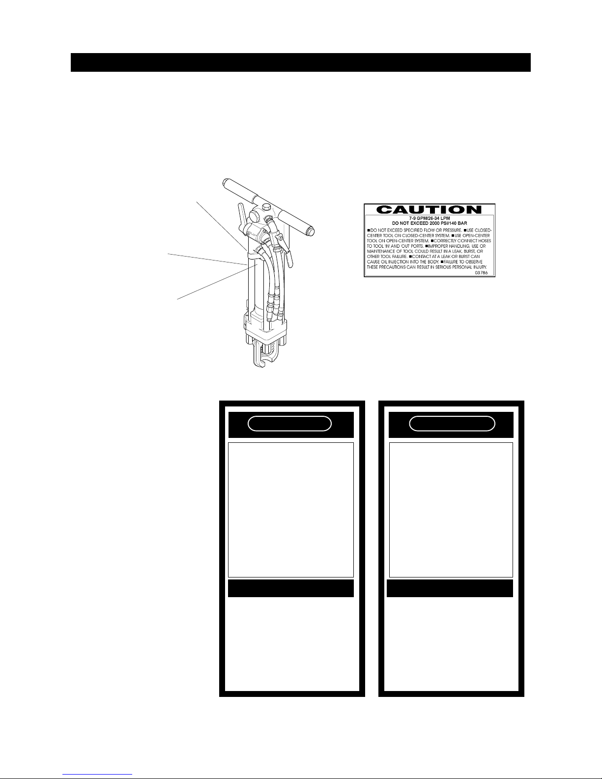
TOOL STICKERS & TAGS
Stickers and decals placed on the tool at time of manufacture are shown below and on the next page. These stickers
and decals have been placed on the tool to aid the operator with safety and general maintenance.
The information listed on these stickers and decals must be legible at all times.
Always replace any sticker or decal that has become worn or damaged. Replacements are available from your
Stanley distributor.
SERIAL NO. STAMPING
04796 Name Tag
03786 GPM STICKER
03786 GPM Sticker
The safety tag (p/n
15875) at right is attached
to the tool when shipped
from the factory. Read
and understand the safety
instructions listed on this
tag before removal. We
suggest you retain this
tag and attach it to the
tool when not in use.
DANGER
1. FAILURE TO USE HYDRAULIC HOSE LABELED AND CERTIFIED AS NON-CONDUCTIVE WHEN USING HYDRAULIC TOOLS
ON OR NEAR ELECTRICAL LINES MAY RESULT IN DEATH OR
SERIOUS INJURY.
BEFORE USING HOSE LABELED AND CERTIFIED AS NON-
CONDUCTIVE ON OR NEAR ELECTRIC LINES BE SURE THE
HOSE IS MAINTAINED AS NON-CONDUCTIVE. THE HOSE
SHOULD BE REGULARLY TESTED FOR ELECTRIC CURRENT
LEAKAGE IN ACCORDANCE WITH YOUR SAFETY DEPARTMENT INSTRUCTIONS.
2. A HYDRAULIC LEAK OR BURST MAY CAUSE OIL INJECTION
INTO THE BODY OR CAUSE OTHER SEVERE PERSONAL INJURY.
A DO NOT EXCEED SPECIFIED FLOW AND PRESSURE FOR
THIS TOOL. EXCESS FLOW OR PRESSURE MAY CAUSE A
LEAK OR BURST.
B DO NOT EXCEED RATED WORKING PRESSURE OF HYDRAU
LIC HOSE USED WITH THIS TOOL. EXCESS PRESSURE MAY
CAUSE A LEAK OR BURST.
C CHECK TOOL HOSE COUPLERS AND CONNECTORS DAILY
FOR LEAKS. DO NOT FEEL FOR LEAKS WITH YOUR HANDS.
CONTACT WITH A LEAK MAY RESULT IN SEVERE PERSONAL
INJURY.
IMPORTANT
READ OPERATION MANUAL AND
SAFETY INSTRUCTIONS FOR THIS
TOOL BEFORE USING IT.
USE ONLY PARTS AND REPAIR
PROCEDURES APPROVED BY
STANLEY AND DESCRIBED IN THE
OPERATION MANUAL.
TAG TO BE REMOVED ONLY BY
TOOL OPERATOR.
SEE OTHER SIDE
SAFETY TAG P/N 15875
(shown smaller than actual size)
15875
DANGER
D DO NOT LIFT OR CARRY TOOL BY THE HOSES. DO NOT
ABUSE HOSE. DO NOT USE KINKED, TORN OR DAMAGED
HOSE.
3. MAKE SURE HYDRAULIC HOSES ARE PROPERLY CONNECTED
TO THE TOOL BEFORE PRESSURING SYSTEM. SYSTEM
PRESSURE HOSE MUST ALWAYS BE CONNECTED TO TOOL
"IN" PORT. SYSTEM RETURN HOSE MUST ALWAYS BE CONNECTED TO TOOL "OUT" PORT. REVERSING CONNECTIONS
MAY CAUSE REVERSE TOOL OPERATION WHICH CAN RESULT IN SEVERE PERSONAL INJURY.
4. DO NOT CONNECT OPEN-CENTER TOOLS TO CLOSED-CENTER HYDRAULIC SYSTEMS. THIS MAY RESULT IN LOSS OF
OTHER HYDRAULIC FUNCTIONS POWERED BY THE SAME
SYSTEM AND/OR SEVERE PERSONAL INJURY.
5. BYSTANDERS MAY BE INJURED IN YOUR WORK AREA. KEEP
BYSTANDERS CLEAR OF YOUR WORK AREA.
6. WEAR HEARING, EYE, FOOT, HAND AND HEAD PROTECTION.
7. TO AVOID PERSONAL INJURY OR EQUIPMENT DAMAGE, ALL
TOOL REPAIR MAINTENANCE AND SERVICE MUST ONLY BE
PERFORMED BY AUTHORIZED AND PROPERLY TRAINED
PERSONNEL.
IMPORTANT
READ OPERATION MANUAL AND
SAFETY INSTRUCTIONS FOR THIS
TOOL BEFORE USING IT.
USE ONLY PARTS AND REPAIR
PROCEDURES APPROVED BY
STANLEY AND DESCRIBED IN THE
OPERATION MANUAL.
TAG TO BE REMOVED ONLY BY
TOOL OPERATOR.
SEE OTHER SIDE
15875
4
Page 7

HYDRAULIC HOSE REQUIREMENTS
HOSE TYPESHOSE TYPES
HOSE TYPES
HOSE TYPESHOSE TYPES
Hydraulic hose types authorized for use with Stanley Hydraulic Tools are as follows:
Certified non-conductive
!!
!
!!
Wire-braided (conductive)
""
"
""
Fabric-braided (not certified or labeled non-conductive)
##
#
##
Hose
Hoses
HOSE SAFETY THOSE SAFETY T
HOSE SAFETY T
HOSE SAFETY THOSE SAFETY T
listed above is the only hose authorized for use near electrical conductors.
!!
!
!!
""
"
""
and
listed above are conductive and must never be used near electrical conductors.
##
#
##
AGSAGS
AGS
AGSAGS
To help ensure your safety, the following DANGER tags are attached to all hose purchased from Stanley Hydraulic
Tools. DO NOT REMOVE THESE TAGS.
If the information on a tag is illegible because of wear or damage, replace the tag immediately. A new tag may be
obtained at no charge from your Stanley Distributor.
The tag shown below is attached to "certified non-conductive" hose.
D A N G E R
1 FAILURE TO USE HYDRAULIC HOSE LABELED AND CERTIFIED AS NON-CONDUCTIVE
WHEN USING HYDRAULIC TOOLS ON OR NEAR ELECTRIC LINES MAYRESULT IN DEATH
OR SERIOUS INJURY.
FOR PROPER AND SAFE OPERATION MAKE SURE THAT YOU HAVE BEEN PROPERLY
TRAINED IN CORRECT PROCEDURES REQUIRED FOR WORK ON OR AROUND ELECTRIC
LINES.
2. BEFORE USING HYDRAULIC HOSE LABELED AND CERTIFIED AS NON-CONDUCTIVE ON
OR NEAR ELECTRIC LINES. WIPE THE ENTIRE LENGTH OF THE HOSE AND FITTING WITH
A CLEAN DRY ABSORBENT CLOTH TO REMOVE DIRT AND MOSISTURE AND TEST HOSE
FOR MAXIMUM ALLOWABLE CURRENT LEAKAGE IN ACCORDANCE WITH SAFETY
DEPARTMENT INSTRUCTIONS.
DO NOT REMOVE THIS TAG
SEE OTHER SIDE
3. DO NOT EXCEED HOSE WORKING PRESSURE OR ABUSE HOSE. IMPROPER USE OR
HANDLING OF HOSE COULD RESULT IN BURST OR OTHER HOSE FAILURE. KEEP HOSE
AS FAR AWAY AS POSSIBLE FROM BODY AND DO NOT PERMIT DIRECT CONTACT
DURING USE. CONTACT AT THE BURST CAN CAUSE BODILY INJECTION AND SEVERE
PERSONAL INJURY.
4. HANDLE AND ROUTE HOSE CAREFULLY TO AVOID KINKING, ABRASION, CUTTING, OR
CONTACT WITH HIGH TEMPERATURE SURFACES. DO NOT USE IF KINKED. DO NOT USE
HOSE TO PULL OR LIFT TOOLS, POWER UNITS, ETC.
5. CHECK ENTIRE HOSE FOR CUTS CRACKS LEAKS ABRASIONS, BULGES, OR DAMAGE TO
COUPLINGS IF ANY OF THESE CONDITIONS EXIST, REPLACE THE HOSE IMMEDIATELY.
NEVER USE TAPE OR ANY DEVICE TO ATTEMPT TO MEND THE HOSE.
6. AFTER EACH USE STORE IN A CLEAN DRY AREA.
D A N G E R
SEE OTHER SIDE
DO NOT REMOVE THIS TAG
3
SIDE 1 SIDE 2
(shown smaller than actual size)
The tag shown below is attached to "conductive" hose.
D A N G E R
SEE OTHER SIDE
1 DO NOT USE THIS HYDRAULIC HOSE ON OR NEAR ELECTRIC LINES. THIS HOSE IS NOT
LABELED OR CERTIFIED AS NON-CONDUCTIVE. USING THIS HOSE ON OR NEAR
ELECTRICAL LINES MAY RESULT IN DEATH OR SERIOUS INJURY.
2. FOR PROPER AND SAFE OPERATION MAKE SURE THAT YOU HAVE BEEN PROPERLY
TRAINED IN CORRECT PROCEDURES REQUIRED FOR WORK ON OR AROUND ELECTRIC
LINES.
3. DO NOT EXCEED HOSE WORKING PRESSURE OR ABUSE HOSE. IMPROPER USE OR
HANDLING OF HOSE COULD RESULT IN BURST OR OTHER HOSE FAILURE. KEEP HOSE
AS FAR AWAY AS POSSIBLE FROM BODY AND DO NOT PERMIT DIRECT CONTACT
DURING USE. CONTACT AT THE BURST CAN CAUSE BODILY INJECTION AND SEVERE
PERSONAL INJURY.
4. HANDLE AND ROUTE HOSE CAREFULLY TO AVOID KINKING, CUTTING, OR CONTACT
WITH HIGH TEMPERATURE SURFACES. DO NOT USE IF KINKED. DO NOT USE HOSE TO
PULL OR LIFT TOOLS, POWER UNITS, ETC.
DO NOT REMOVE THIS TAG
HOSE PRESHOSE PRES
HOSE PRES
HOSE PRESHOSE PRES
D A N G E R
5. CHECK ENTIRE HOSE FOR CUTS CRACKS LEAKS ABRASIONS, BULGES, OR DAMAGE TO
COUPLINGS IF ANY OF THESE CONDITIONS EXIST, REPLACE THE HOSE IMMEDIATELY.
NEVER USE TAPE OR ANY DEVICE TO ATTEMPT TO MEND THE HOSE.
6. AFTER EACH USE STORE IN A CLEAN DRY AREA.
SEE OTHER SIDE
SIDE 1 SIDE 2
SURE RASURE RA
SURE RA
SURE RASURE RA
TINGTING
TING
TINGTING
(shown smaller than actual size)
The rated working pressure of the hydraulic hose must be equal to or higher than the relief valve setting on the
hydraulic system.
5
DO NOT REMOVE THIS TAG
Page 8

HYDRAULIC SYSTEM REQUIREMENTS
• The hydraulic system should provide a flow of 7-9
gpm/26-34 lpm at an operating pressure of 2000 psi/140
bar. Recommended relief valve setting is 2100-2250
psi/145-155 bar.
• The system should have no more than 250 psi/17 bar
backpressure measured at the tool end of the operating
hoses. The system conditions for measurement are at
maximum fluid viscosity of 400 ssu/82 centistokes
(minimum operating temperatures).
• The hydraulic system should have enough heat
rejection capacity to limit the maximum oil temperature
to 140°F/60°C at the maximum expected ambient
temperature.
• The hydraulic system should have a minimum of 25
micron filtration. Stanley recommends using filter
The SK58 Sinker Drill is designed to be used to drill
holes in rock such as blast holes.
A rock bit containing carbides is attached to drill steel
which is inserted into the tool. The tool incorporates a
reciprocating piston and a varible speed hydraulic
motor. During the drilling process, the piston hammers
on the drill steel and the hydraulic motor rotates the drill
steel. It is the pounding and rotating motion of the rock
bit that causes the rock to fracture into small cuttings.
It is necessary to extract the rock shavings during the
drilling process. If the rock shavings are not extracted,
the rock bit will sit on top of the shavings, which in
turn, will prevent the rock bit from penetrating into the
rock.
On SK58110, SK58120, and SK58310 models, air is
introduced into the drill steel via a valve in the tool to
blow the rock cuttings out of the hole. On the SK58130
model, water is used to flush out the rock cuttings.
elements sized for a flow of at least 30 gpm/114 lpm for
cold temperature startup and maximum dirt holding
capacity.
• The hydraulic fluid used should have a viscosity
between 100 and 400 ssu/20 and 82 centistokes at the
maximum and minimum expected operating temperatures. Petroleum base hydraulic fluids with antiwear
properties and a viscosity index over 140 ssu/28
centistokes will meet the recommended requirements
over a wide range of operating temperatures.
• The recommended hose size is .500 inch/12 mm I.D.
up to 50 ft/15 m long and .625 inch/16 mm I.D. minimum up to 100 ft/30 m long.
• Quick disconnect couplings must conform to NFPA
T3.20,15/EHTMA specifications.
PRINCIPLE OF OPERATION
factor for the particular application. Incorrect rotation
speed and/or inadequate extraction of the rock cuttings
will significantly reduce drilling effectiveness and result
in substantially increased drilling time.
The tool can drill up to a 3 in./75 mm hole up to 20 feet/
6 meters deep in rock. The tool has been used for other
applications such as dowel drilling and gas leak detection.
Because the tool has been specifically designed to be
operated by an individual, it should never be mounted to
and operated from a machine such as a drilling rig or
small excavator. If a requirement exists to machine
mount the tool, the application must first be approved by
Stanley Engineering. Failure to obtain this approval can
result in tool failure and void the warranty.
See the "OPERATING INSTRUCTIONS" section of this
manual for specific operating instructions.
The air requirements for effective drilling are 30 cfm at
120 psi. The air supply is furnished by an air compressor.
SK58 Sinker Drills are designed to be operated and
controlled by one individual. The rotation speed of the
drill steel and amount of air introduced into the drill
steel is adjusted by the operator based on an experience
6
Page 9

PREOPERATION PROCEDURES
Preparation For Initial Use
The tool, as shipped, has no special unpacking or
assembly requirements prior to usage. Inspection to
assure the tool was not damaged in shipping and does
not contain packing debris is all that is required.
OPERATING INSTRUCTIONS
1. Thread a rock bit onto the drill steel.
2. Rotate the latch (61) out and up.
3. Slide the drill steel into the tool.
4. Rotate the latch down being careful not to pinch
your fingers. When correctly installed, the collar on
the drill steel should be above the bottom of the
latch.
Check Hydraulic Power Source
1. Using a calibrated flowmeter and pressure gauge,
check that the hydraulic power source develops a
flow of 7-9 gpm/26-34 lpm at 1500-2000 psi/105140 bar.
2. Make certain the hydraulic power source is equipped
with a relief valve set to open at 2100-2250 psi/145155 bar minimum.
3. Check that the hydraulic circuit matches the tool for
open-center (OC) operation.
Check Tool
1. Make sure all tool accessories are correctly installed.
Failure to install tool accessories properly can result
in damage to the tool or personal injury.
2. There should be no signs of leaks.
3. The tool should be clean, with all fittings and
fasteners tight.
Connect Hoses
1. Wipe all hose couplers with a clean lint-free cloth
before making connections.
2. Connect the hoses from the hydraulic power source
to the hose couplers on the tool. It is a good practice
to connect the return hose first and disconnect it last
to minimize or avoid trapped pressure within the
tool.
3. Observe flow indicators stamped on hose couplers
to be sure that oil will flow in the proper direction.
The female coupler is the inlet coupler.
NOTE: The pressure increase in uncoupled
hoses left in the sun may result in making
them difficult to connect. When possible,
connect the free ends of operating hoses
together.
4. Connect the hose from the air supply to the hose on
the tool.
Check Trigger Mechanism
1. Check that the trigger operates smoothly and is free
to travel between the "ON" and "OFF" positions.
Install Drill Steel & Rock Bit
Use standard 4-1/4 inch shank by 1 inch hex drill steel
for SK58110, SK58120 and SK58310 models. Use 4-1/
4 inch shank by 7/8 inch hex drill steel for the SK58130
model.
Drill steels are available in a variety of lengths. Start
with a short length so that the tool may be operated at a
normal standing position. The tool handles should
never exceed chest height during operation.
7
The air supply must be minimum 30 cfm at
120 psi. Supplying less than these specifications may result in inadequate extraction
of rock cuttings; cause cuttings to migrate
up the drill steel and into the tool and result
in tool damage; diminish drilling time; and
cause premature wear of the drill bit.
OPERATING PROCEDURES
1. Observe all safety precautions. Make sure you are
wearing eye protection, earing protection, foot
protection, and head protection.
Page 10

2. Start the hydraulic supply and turn the circuit
control valve to the "ON" position.
COLD WEATHER OPERATION
3. Open the air valve on the tool just enough to permit
a small amount of air to flow from the rock bit.
Air flow must be continuous during drilling to avoid clogging of air passages and/
or backflushing of waste products into the
drill.
4. Place the rock bit firmly on the surface to be drilled.
5. Grip the handles on the tool firmly and open the
hydraulic valve lever slightly to start the tool at a
slow speed. Adequate down pressure is very
important.
6. Ensure the rock bit is rotating at a moderate speed
(not too fast, not too slow). When starting the hole,
it is best to start at a slow impact and rotation speed
until the rock bit has carved out a depression in the
material being drilled. If the rock bit is not rotating
open the hydraulic valve lever further. If the rock bit
still does not rotate adjust the motor control knob
until rotation is achieved.
If the tool is to be used during cold weather, preheat the
hydraulic fluid at low engine speed. When using the
normally recommended fluids, fluid temperature should
be at or above 50° F/10° C (400 ssu/82 centistokes)
before use.
ROUTINE MAINTENANCE
A very important maintenance practice is to keep the
hydraulic fluid clean at all times. Contaminated hydraulic fluid causes rapid wear and/or failure of internal
parts.
Periodically apply a light coat of WD40™ between the
throttle lever and throttle valve and the motor control
knob and motor control valve.
Check the nitrogen charge in the accumulator. If low,
recharge the accumulator. See the section titled "ACCUMULATOR CHARGING" found later in this manual.
7. After the rock bit has carved out a depression in the
material being drilled, open the hydraulic valve
lever fully. Readjust the motor control knob to
obtain a good drilling speed. Adjust the air valve to
ensure the cuttings are being extracted from the drill
hole.
8. When the bottom of the tool comes within 6 inches
of the drill hole, it is time to either add another
section of drill steel or replace the existing drill steel
with a longer section. Close the hydraulic valve
lever but leave the air valve "ON" and then lift the
tool with drill steel and rock bit out of the hole.
Leaving the air valve "ON" helps prevent cuttings
from falling around the bit while the bit is lifted
from the hole.
9. When the tool, drill steel and bit have been removed
from the drill hole, turn the valve lever "OFF" and
turn the hydraulic supply circuit control valve
"OFF" before changing the drill steel or rock bit.
STORAGE
Disconnect all hoses and wipe the tool clean. Spray the
interior of the drive hex and motor plate with WD40™.
Also apply a light coat of WD40™ between the throttle
lever and throttle valve and the motor control knob and
motor control valve.
Store in a clean, dry place.
8
Page 11

SERVICE INSTRUCTIONS
Good maintenance practices will keep the tool on the
job and increase its service life.
A very important maintenance practice is to keep the
hydraulic fluid clean at all times. Contaminated hydraulic fluid causes rapid wear and/or failure of internal
parts.
Follow the procedures contained in the HYDRAULIC
SYSTEM REQUIREMENTS section of this manual to
ensure peak performance from the tool. Never disassemble the tool unless proper troubleshooting procedures have isolated the problem to an internal part.
Then, only disassemble it to the extent necessary to
replace the defective part.
KEEP CONTAMINANTS SUCH AS DIRT AND GRIT AWAY
FROM INTERNAL PARTS AT ALL TIMES.
DO NOT ATTEMPT TO SERVICE THIS TOOL IF YOU
ARE NOT THOROUGHL Y TRAINED IN THE PROPER
DISASSEMBL Y AND ASSEMBLY OF THIS TOOL.
IMPROPER DISASSEMBL Y OR ASSEMBLY MAY
RESULT IN BODILY INJURY AND DAMAGE TO THE
TOOL. ALWAYS REFER ALL MAINTENANCE TO A
QUALIFIED AND TRAINED TECHNICIAN.
2. Swing the latch (61) away from the motor plate (68).
Install the latch removal tool over the retaining ring
(62), spring back-up (63).
3. Use 2 "C" clamps or bar clamps to squeeze the latch
removal tool against the spring so that the spring
back-up and spring are depressed enough to expose
the retaining ring. Pry the retaining ring out.
4. Slowly release the clamps and remove them.
Remove the spring back-up, spring, latch washer
(65), and latch.
LATCH RE-ASSEMBLY
1. Install the latch, latch washer, spring and spring
back-up onto the motor plate with orientation as
shown in the parts drawing.
2. Place the retaining ring in the groove in the latch
removal tool. Install the latch installation tool into
the recessed bore of the latch removal tool. The
retaining ring should now be between the latch
removal tool and the latch installation tool. Place
this assembly over the spring back-up with the
protuding end of the latch installation tool inserted
into the bore of the motor plate.
3. Using a large mallet, strike the face of the latch
removal tool with one swift blow. This should push
the retaining ring into place.
Always determine and correct the cause of the problem
prior to reassembly. Further wear and tool failure can
result if the original cause is not corrected.
PRIOR TO DISASSEMBLY
• Clean the exterior of the tool.
• Obtain a seal kit to replace all seals exposed during
disassembly. Note the orientation of seals before
removing them. Install new seals in the same
position as original seals.
LATCH AND SPRING SERVICE
1. Obtain Stanley special tools latch removal tool (p/n
05045) and latch installation tool (p/n 05062).
9
THROTTLE VALVE SERVICE
The throttle valve can be serviced without disassembling
the entire tool. Follow the instructions below.
1. Remove the valve lever (8) by unscrewing the
locknut (7). Lift out the key (47).
2. Remove the retaining ring (9), washer (10), kap seal
(11) and o-ring (6).
3. Remove the inlet flange (35) by unscrewing and
removing the 2 capscrews (36). Push the throttle
valve (42) out of the accumulator housing toward
the inlet flange side. Remove the o-ring (38) and
kap seal (37), washer (39), kap seal (40) and o-ring
(41).
4. Inspect the surface of the throttle valve and the
Page 12

throttle valve bore of the accumulator housing for
damage. A light surface scuffing is normal. If deep
scratches or nicks are noticed, replace the part(s).
3. Lift off the drive motor control block (82).
4. Unscrew and remove the 2 capscrews (67).
THROTTLE VALVE RE-ASSEMBLY
1. Apply grease and install a new o-ring (41) into the
channel in the kap seal (40) and then install the
assembly into the throttle valve bore of the accumulator housing. When correctly installed, the o-ring
faces the wall of the bore. Apply grease and install
the washer (39).
2. Lubricate the throttle valve with clean hydraulic
fluid and install it into the throttle valve bore of the
accumulator housing with the key way facing
upward toward the handles on the accumulator
housing.
3. Apply grease and install a new kap seal (37) into the
groove located on the inlet flange (35) (throttle
valve side). Ensure the channel in the kap seal is
facing outward. Apply grease and install a new
o-ring (38) into the channel in the kap seal. Install
the inlet flange and secure with 2 capscrews (36).
4. Apply grease and install a new o-ring (6) into the
channel in the kap seal (11). Install the assembly,
followed by the washer (10), over the throttle valve
and into the bore. Press on the washer with the
appropriate o-ring tool to aid in the assembly. When
correctly installed, the o-ring faces the wall of the
bore.
5. Install the retaining ring (9), key (47), valve lever
(8), and secure with the locknut (7).
5. Lift off the motor plate (68) being careful to prevent
the gears from falling out.
6. Lift out the idler gear (72) and drive gear (99).
7. Remove the woodruff key (77) and push the drive
hex (76) out of the drive motor chamber (75).
8. If it is necessary to remove the latch, refer to the
section titled "LATCH AND SPRING SERVICE".
9. If it is necessary to remove the bushings (70 & 71),
obtain the following Stanley special tools.
Collet, p/n 05871 - used to remove item 71.
Actuator Pin, p/n 05067 - used with p/n 05871
Collet, p/n 5068 - used to remove item 70.
Actuator Pin, p/n 05067 - used with p/n 05068
Bearing Installation Tool, p/n 05061
Bearing Installation Tool, p/n 05044
A collet is inserted into the bearing until the lip on
the collet is under the bearing. The actuator pin is
then inserted into the collet to cause the collet to
spread. A puller is installed to the actuator to apply
force to pull the bearing out.
Bearing installation tools are inserted into the
bearing and then used with an arbor press to press
the bearing into the bore. Use of a bearing installation tool ensures a straight bearing to bore installation and correct depth.
6. Test the function of the throttle valve by rotating the
valve lever back and forth. The lever should rotate
with ease. If it seems the throttle valve is binding,
disassemble the throttle valve and inspect the parts
for damage. If damage is noted, replace the part(s).
HYDRAULIC MOTOR SERVICE
The hydraulic motor assembly can be serviced without
disassembling the entire tool. Follow the instructions
below.
1. Complete steps 1, 2, 6, and 7 under "ACCUMULATOR HOUSING, FLOW SLEEVE, PISTON, &
AUTOMATIC VALVE SERVICE".
2. Unscrew and remove the 3 capscrews (95).
10. Loosen the set screw (86) in the knob (87) and
remove the knob. Unscrew and remove the valve
guide (88). Reinstall the knob and setscrew and then
unscrew the motor control valve (89) to remove it.
INSPECTION AND CLEANING
Inspect and clean all parts as follows:
Cleaning
Clean all parts with a degreasing solvent. Blow dry with
compressed air and wipe clean. Use only lint-free
cloths.
Drive Motor Chamber
The chamber bores and bottoms around the bushings
should be polished and not rough or grooved. If the
10
Page 13

bushing bores are yellow-bronze, replace them and
investigate the cause of wear.
4. Install the woodruff key (77) into the slot in the
drive hex.
The flat surfaces around the chamber and bolt holes
should be flat and free of nicks or burrs that could cause
misalignment or leaks.
Bushings
The inside of the bushings should be gray with
some bronze showing through. If significant yellowbronze shows, replace the bushings. Inspect the drive
hex and idler gear for corresponding wear and replace as
required.
Gears
The drive and idler gears should have straight tips
without nicks; square tooth ends and a smooth even
polish on the teeth and end faces. Check for cracks
between the drive gear keyway and gear tooth root.
Replace the gear if cracks are present.
Motor Plate
The surface near the gears should show two interconnecting polished circles without a step.
Drive Hex and Idler Gear Shaft
The surface diameter at the bushing and seal locations
must be smooth. Grooves, roughness or a reduced
diameter indicate fluid contamination or damaged
bushings. If abnormal wear as above occurs (more than
normal polishing), replace the drive hex, idler gear and
associated bushings.
Also check the hydraulic system for excess contamination in the fluid and for filter condition.
MOTOR RE-ASSEMBLY
5. Lubricate the idler gear (72) and drive gear (99)
with clean hydraulic fluid and then install them into
the drive motor chamber.
6. Apply grease and install a new o-ring (73) into the
groove in the drive motor chamber.
7. Install the motor plate to the drive motor chamber
and secure with 2 capscrews (67). Check that the
drive hex rotates freely.
8. Install the thrust washer (98) and thrust back-up
washer (97) over the drive hex and against the drive
motor chamber.
9. Install a new gasket (79) onto the drive motor
chamber.
10. Install the drive motor control block to the drive
motor chamber and secure with 3 capscrews (95).
Check that the drive hex rotates freely.
11. Apply grease and install a new cup seal (93) into the
drive motor control block, lips facing down. Install
the seal washer (92) on top of the cup seal. Apply
grease and install a new rod seal (91) on top of the
washer, lips facing up.
12. Apply grease and install a new o-ring (90) into the
groove on the drive motor control block.
13. Apply grease and install a new o-ring (84) into the
groove in the motor control valve (89). Install new
nylon cap locks (83) to the motor control valve.
Install the knob (86) and tighten the set screw.
Thread the motor control valve into the drive motor
control block. Loosen the set screw and remove the
knob.
1. If new bushings were installed (see paragraph 9
under "HYDRAULIC MOTOR SERVICE", ensure each
bushing is flush with the surface of the part the bushing
is installed into. If the bushing sits higher than the
surface of the part, it will cause binding of related
components.
2. Apply grease and install a new back-up ring (81)
and a new quad ring (80) into the motor plate (68)
and into the drive motor control block (82).
3. Lubricate the drive hex (76) with clean hydraulic
fluid and install it into the drive motor chamber
(75).
11
14. Apply grease and install a new o-ring (85) onto the
valve guide (88). Place the valve guide over the
motor control valve and thread it into the drive
motor control block. Tighten it securely. Re-install
the knob and tighten the setscrew.
15. Install the motor over the side rods and into the flow
sleeve tube ensuring the roll pin is correctly aligned
with the hole in the flow sleeve (31) and the motor
control valve is oriented correctly with the handles.
16. Install the 4 side rod nuts. Tighten in 20 ft lb/25 Nm
increments to 75 ft lb/100 Nm in a cross pattern.
Page 14

MOTOR BREAK-IN
Motor break-in is required whenever major components
of the motor have been replaced. Break-in the motor by
operating the tool with the motor control valve fully
open for approximately 15 minutes. Do not attempt to
drill with the tool during the break-in period.
ACCUMULATOR HOUSING,
ACCUMULATOR, FLOW SLEEVE,
PISTON, AND AUTOMATIC VALVE
SERVICE
1. Secure the tool in a bench vise, with the “IN” and
“OUT” ports up, clamping on the flow sleeve tube
between the side rods. Soft vise jaws are recommended.
2. Remove the pigtail hose assemblies.
b. If the valve body remains in the flow sleeve
tube when the accumulator housing is separated
from the tube, proceed with step 9.
9. Skip this step if the valve body remained with the
accumulator housing assembly when separated from
the flow sleeve tube. Grasp the valve body with one
hand and slide the valve body off of the piston and
away from the flow sleeve. Use your other hand to
prevent the washer, automatic valve, and push pins
from falling out. Remove the washer, automatic
valve, and 2 push pins. Do not use a magnet to
remove the push pins.
10. Slide the piston (29) out of the flow sleeve (31).
Slide it toward the accumulator housing end of the
flow sleeve.
11. Remove the flow sleeve tube from the vise and
position it over a work bench so as to allow the push
pins (58) to drop out. Hold a finger over the flow
sleeve to prevent it from sliding out of the flow
sleeve tube.
Note: The tool is full of fluid and will drip from the
ports when the hoses are removed.
3. Remove the charge valve cap (12) (1-3/8 inch hex). .
Loosen the 5/8 inch hex lock nut on the charging
valve (14) 1-1/2 turns. Using a small punch, depress
the stem in the charge valve to discharge the
accumulator completely.
4. Remove the charge valve.
5. Remove the blower tube nut (43).
6. Remove the four side rod nuts (66) (1 inch hex).
7. Using a soft faced mallet, tap on the edges of the
motor assembly to drive it from the flow sleeve tube
(30).
8. Remove the accumulator housing assembly (46)
from the flow sleeve tube by tapping on alternate
ends of the side rods (78) with a soft faced mallet.
Be careful to prevent the washer (27), valve body
(56), automatic valve (32), and push pins (57) from
falling out when the accumulator housing assembly
is separated from the flow sleeve tube.
a. If the valve body remains in the accumulator
housing assembly, lift the automatic valve and
push pins out immediately after the accumulator
housing assembly separates from the flow
sleeve tube. Set the accumulator housing
assembly aside.
12. Holding the flow sleeve tube in one hand, push on
the flow sleeve to slide it out of the flow sleeve tube.
The flow sleeve may be removed from the flow
sleeve tube from either end of the tube. Use extreme
care in handling the flow sleeve as it contains very
sharp edges which can cut you. If the flow sleeve
does not seem to be easily removeable from the flow
sleeve tube, do not remove it unless necessary. To
assist in the removal of a flow sleeve that has proven
difficult to remove, use the following procedures.
a. Place the Stanley special split ring tool (p/n
04908) on top of the Stanley special flow
sleeve removal tool (p/n 04910). Place the flow
sleeve tube on top of the split rings. Using an
arbor press and the Stanley special accumulator cylinder puller tool (p/n 05640) to protect
the flow sleeve, push the flow sleeve out of the
tube.
13. Obtain the accumulator housing assembly. Insert
Stanley special accumulator removal tool (p/n
05639) or a 1/2-20 long threaded rod through the
blower tube nut hole and thread it into the top of the
accumulator. Tap on the special tool or rod with a
mallet to drive the accumulator assembly (22, 23,
24, 25, & 26) out of the accumulator housing. If the
valve body is in the accumulator housing it will be
driven out along with the accumulator assembly.
Make sure the washer (27) between the valve body
and accumulator is properly located in its
counterbore before driving out the valve body and
12
Page 15

accumulator. If the washer is not properly located,
the parts will be damaged. If the entire accumulator
assembly is removed, proceed to step 14. If the
accumulator cylinder (22) remains in the accumulator housing, it can be removed using the following
procedures.
a. If the entire accumulator assembly was re-
moved, skip this step and proceed to step 14.
Assemble the Stanley special accumulator
cylinder puller tool (p/n 05640) to a slide
hammer containing a 1/2 inch diameter shank.
Insert the puller tool into the bottom of the
accumulator cylinder so that it seats on the
inside lower contour of the cylinder. Hammer
the cylinder out of the accumulator housing.
are seated correctly to the accumulator chamber
before completing the assembly. Use an arbor press
to completely seat the assembly using short movements during the last 1/2 inch/12 mm of travel to
gently seat the diaphragm.
4. Apply grease and install a new o-ring (21) into the
groove on the accumulator cylinder.
5. Apply grease and install the back-up washer (25)
and a new cup seal (26) (lips facing out) in the
accumulator chamber counterbore.
6. Apply grease and install new o-rings (101) into the
grooves on the tube connector. Install the tube
connector into the accumulator chamber.
14. Remove the tube connector (102) by pulling it out of
the accumulator chamber.
15. To remove the accumulator chamber and
diaphragem (23) from the accumulator cylinder,
place the accumulator assembly on Stanley special
disassembly tools (p/n 05508 ring and p/n 04910
tube). Place a rag in the bottom of the tube to protect
the accumulator chamber when it is removed. Drive
the chamber and diaphragm out of the cylinder by
tapping on the charge valve end of the chamber with
a maller or pushing on it with an arbor press.
16. Squeeze the accumulator diaphragm and slide it off
the charge valve end of the accumulator chamber.
17. Remove the cup seal (26) and back-up washer (25)
from the accumulator chamber.
18. Remove the air tube (1) (or water tube if applicable).
ACCUMULATOR RE-ASSEMBLY
1. Apply grease and install a new o-ring (100) into the
groove on the accumulator chamber. NOTE: This oring was only used on early models. It was eliminated on later models.
FLOW SLEEVE, PISTON, & AUTOMATIC
VALVE RE-ASSEMBLY
The best way to assemble the flow sleeve (31), automatic valve body (56) and piston (29) is by using an
assembly fixture such as that shown in figure 1. The
fixture permits the parts to be stacked vertically during
the assembly process. After the parts are stacked, the
handle assembly can then be placed on top of the
stacked parts and tapped into place.
The assembly fixture shown in figure 1 should be
constructed of aluminum or brass and should be at least
3-1/2 in/88 mm high but no more than 8 in/203 mm
high.
2. Apply a light coating of WD-40™ to the accumulator diaphragm (23) and accumulator chamber (24).
Slide the accumulator diaphragm onto the accumulator chamber from the tube connector (102) end.
3. Use grease or rubber lubricant on the inside of the
accumulator cylinder (22) and the outside diameter
of the diaphragm. Push the accumulator chamber
and diaphragm, tube connector end first, halfway
into the accumulator cylinder. Be sure the accumulator diaphragm is free of wrinkles and the seal beads
13
Figure 1.
1. Lubricate the flow sleeve with clean hydraulic fluid
and install it into the flow sleeve tube (30). The flow
sleeve has a wide groove around the outside of one
end. Install this end first. Then place the flow sleeve
tube and flow sleeve on top of the assembly fixture
shown in figure 1.
Page 16

2. Apply grease and install an o-ring (21) onto the flow
sleeve tube.
3. Apply clean hydraulic fluid and install 4 push pins
(58) into the holes in the top of the flow sleeve tube.
One end of each push pin contains a machined
surface. This surface must be facing up as each push
pin is installed. Each push pin must slide freely in or
out of the hole. If a push pin does not slide freely or
seems to stick, the hole may contain contamination
or the top edge of the hole contains a burr. Remove
burrs with a deburring tool, clean the hole thoroughly and try the push pin again.
4. Tap the roll pin (33) into the hole on the automatic
valve body (56).
11. Install the accumulator assembly over the stem of
the piston and down to the top of the automatic
valve body.
12. Insert the air tube (1) (or water tube if applicable)
into the top of the accumulator ensuring it aligns
with the hole in the piston.
13. Use a felt tip marker to place a mark on the accumulator cylinder and the accumulator housing to align
the tube connector with the port in the accumulator
housing.
14. Apply grease liberally to the o-ring surfaces on the
accumulator, automatic valve body, flow sleeve tube
and to the bore of the accumulator housing.
5. Apply grease and install an o-ring (21) onto the
automatic valve body.
6. Lubricate with clean hydraulic fluid and install 2
push pins (57) into the holes in the valve body. One
end of each push pin contains a machined surface.
This surface must be facing up as each push pin is
installed. Each push pin must slide freely in or out
of the hole. If a push pin does not slide freely or
seems to stick, the hole may contain contamination
or the top edge of the hole contains a burr. Remove
burrs with a deburring tool, clean the hole thoroughly and try the push pin again.
7. Lubricate the automatic valve (32) with clean
hydraulic fluid and install it into the valve body.
The automatic valve must freely slide back and
forth. If it does not, the valve body or valve may
contain contaminants or the bore of the valve body
contains burrs. Remove the push pins and scrub the
bore of the valve body with emery cloth and then
thoroughly clean the bore, push pin holes and valve.
Reinstall the push pins and valve.
8. Grasp the automatic valve body and valve so that
one or more fingers are gripping the valve to prevent
it and the push pins from falling out when the valve
body and valve are turned upside down (roll pin
facing down). Place the assembly on top of the flow
sleeve making sure the roll pin aligns with the
appropriate hole in the flow sleeve.
15. Place the accumulator housing over the top of the
accumulator, ensure that the felt pen marks are
alligned, and then tap it down until the lower part of
the housing covers the o-ring on the flow sleeve
tube.
16. Lay the completed assembly on its side being careful
to prevent movement of the flow sleeve. Remove the
assembly fixture.
17. Place the completed assembly horizontally in a vice
with soft jaws, oil ports up, and clamp on the flow
sleeve tube.
18. Apply grease and Install a new cup seal (93) with
lips facing down, the washer (92), new rod seal (91)
with lips facing up, and a new o-ring (90).
19. Install the motor over the side rods and into the flow
sleeve tube ensuring the roll pin is correctly aligned
with the hole in the flow sleeve and the motor
control valve is oriented correctly with the handles.
20. Install the 4 side rod nuts. Tighten in 20 ft lb/25 Nm
increments to 75 ft lb/100 Nm in a cross pattern.
21. Apply grease and install new o-rings (44 & 45) to
the blower tube nut. Install the blower tube nut to
the accumulator housing.
22. Install the charge valve (14).
9. Lubricate the piston (29) with clean hydraulic fluid
and install into the top of the automatic valve body.
Apply grease and install a new o-ring (28) into the
groove in the piston (water flush models only).
10. Install the washer (27), smaller diameter first, over
the stem of the piston and onto the automatic valve
body.
23. Charge the accumulator with 600 psi/42 bar nitrogen
as described in the "CHARGING THE ACCUMULATOR" section of this manual.
24. Apply grease and install a new o-ring (13) onto the
charge valve cap (12). Install the charge valve cap.
14
Page 17

CHARGING THE ACCUMULA TOR
ACCUMULATOR CHARGING
To check or charge the accumulator the following
equipment is required:
• Accumulator tester (Part Number 02835).
• Charging assembly (Part Number 06545) (includes a
regulator, hose and fitting).
• NITROGEN bottle with a 800 psi/56 bar minimum
charge.
1. On charge valves containing 5/8 inch hex locking
nuts, first loosen the locking nut 1-1/2 turns.
2. Holding the chuck end of the Stanley tester (p/n
02835), turn the gauge fully counterclockwise to
ensure the stem inside the chuck is completely
retracted.
3. Thread the tester onto the charging valve of the tool
accumulator (do not advance the gauge-end into the
chuck end. Turn as a unit). Seat the chuck on the
accumulator charging valve and hand tighten only.
4. Advance the valve stem by turning the gauge- end
clockwise.
5. Connect the charging assembly to the valve on the
tester.
6. Adjust the regulator on the nitrogen bottle to 600
psi/42 bar.
NOTE: It may be necessary to set the regulator at
650-700 psi/45-48 bar to overcome any pressure
drop through the charging system.
7. Open the valve on the charging assembly hose.
When the tester gauge reads 600 to 700 psi/42 to 48
bar, close the valve on the charging assembly hose
and remove the charging assembly.
8. Turn the gauge end of the tester fully counterclockwise to retract the plunger in the chuck. Remove the
tester from the charge valve.
9. On charge valves containing 5/8 inch hex locking
nuts, tighten the locking nut.
TESTING THE ACCUMULATOR
PRESSURE
1. Follow instructions 1 through 4 under "CHARGING
THE ACCUMULATOR".
2. Read the pressure on the gauge (pressure should be
between 500 & 600 psi/35 & 42 bar.
3. If the pressure is low, recharge the tool.
Regulator
06545 ACCUMULA TOR
CHARGE KIT
Includes: Regulator, hose
and charge fitting.
Nitrogen Tank
Hose w/
Charge Fitting
Gauge
Charging Valve
Chuck
02835 TESTER
15
Page 18

TROUBLE SHOOTING
If symptoms of poor performance develop, the following chart can be used as a guide to correct the problem.
When diagnosing faults in operation of the tool, always
check that the hydraulic power source is supplying the
correct hydraulic flow and pressure to the tool as listed
PROBLEM CAUSE SOLUTION
Tool doesn’t run. Power unit not functioning. Check power unit for proper
Couplers or hoses blocked. Remove obstruction.
Pressure and return line hoses Be sure hoses are connected to
reversed at ports. the proper ports.
Mechanical failure of piston or Disassemble drill and inspect
automatic valve. for damaged parts.
Tool doesn’t drill effectively. Power unit not functioning. Check power unit for proper
in the table. Use a flowmeter known to be accurate.
Check the flow with the hydraulic oil temperature at
least 80°F/27°C.
flow and pressure (7-9 gpm
@ 1500-2000 psi).
flow and pressure (7-9 gpm @
1500-2000 psi).
Couplers or hoses blocked. Remove obstruction.
Insufficient air or water 20 cmf minimum.
Accumulator charge (pressure Recharge accumulator. Replace
hose pulses more than normal). diaphragm if charge loss
continues.
Oil too hot (above 140°F). Provide cooler to maintain
proper oil temperature
(under 140°F).
continued
16
Page 19

PROBLEM CAUSE SOLUTION
Tool operates slow Low gpm supply from power unit. Check power unit for proper
flow (7-9 gpm)
High backpressure. Check hydraulic system for
excessive backpressure
(over 250 psi).
Couplers or hoses blocked. Remove obstruction.
Orifice plug blocked. Remove restriction.
Oil too hot (above 140°F) Check power unit for proper oil
or cold (below 60°). temperature. Bypass cooler to
warm oil up, or provide cooler to
maintain proper temperature.
Relief valve set too low. Adjust relief valve to
2100-2250 psi.
Tool gets hot. Hot oil going through tool. Check power unit. Be sure flow
rate is not too high causing part
of the oil to go through the
relief valve. Provide cooler to
maintain proper oil temperature
(under 140°F).
Check relief valve setting.
Oil leakage on drill steel. Lower piston or drive hex Replace seals.
seal failure.
Oil leakage through charge Upper piston seal failure or Replace seals, recharge or
valve cap. accumulator or o-ring failure replace accumulator
or accumulator charge loss diaphragm.
or failure.
Oil leakage around trigger. Valve spool seal failure. Replace seals.
Low rotation torque. Motor not completely broken in. Continue operation to break in
motor.
Excessive oil temperature Provide cooler to maintain oil
causes operating pressure loss. temperature (under 140°F).
Damage to motor clearances. Repair as required.
Insufficient air or water. 20 CFM minimum.
Mechanical binding during drilling. Take care to guide drill straight.
17
Page 20

SPECIFICATIONS
Pressure Range ............................................................................................................................................ 1500-2000 psi/104-140 bar
Shank Size (SK58110 (Air) ,SK58120 (Water) , & SK58310 UW (Air)........................................................................4-1/4 in. x 1 in. hex
Shank Size (SK58130(Air ) ................................................................................................................................4-1/4 in. x 7/8 in. hex
Maximum Back Pressure .................................................................................................................................................. 250 psi/17 bar
Flow Range ................................................................................................................................................................ 7-9 gpm/26-34 lpm
Porting................................................................................................................................................................................-8 SAE O-ring
Couplers............................................................................................................................................................................... Not Included
Connect Size and Type................................................................................................................................... 3/8 in. Male Pipe Adapter
Hose Whips ................................................................................................................................................................................Included
Weight ......................................................................................................................................................................... 67 lbs / 30 kg
Overall Length ................................................................................................................................................................... 26 in. / 66 cm
Overall Width - Standard Handle....................................................................................................................................... 18 in. / 46 cm
Maximum Fluid Temperature .............................................................................................................................................. 140° F/60° C
ACCESSORIES
DESCRIPTION PART NUMBER
Drill Steels for Use with Air
1 in. Hex x 4-1/4 in. H thread, 12 in./30 cm U/C 05168
1 in. Hex x 4-1/4 in. H thread, 18 in./46 cm U/C 05169
1 in. Hex x 4-1/4 in. H thread, 24 in./61 cm U/C 05170
1 in. Hex x 4-1/4 in. H thread, 36 in./91 cm U/C 04915
1 in. Hex x 4-1/4 in. H thread, 48 in./122 cm U/C 05171
1 in. Hex x 4-1/4 in. H thread, 72 in./183 cm U/C 08905
1 in. Hex x 4-1/4 in. H thread, 96 in./244 cm U/C 08906
7/8 in. Hex x 4-1/4 in. H thread, 12 in./30 cm U/C 05172
7/8 in. Hex x 4-1/4 in. H thread, 24 in./61 cm U/C 05174
7/8 in. Hex x 4-1/4 in. H thread, 36 in./91 cm U/C 05175
7/8 in. Hex x 4-1/4 in. H thread, 48 in./122 cm U/C 05176
Drill Steels for Use with Water
1 in. Hex x 4-1/4 in. 125 Rope Thread, 48 in./122 cm U/C 05189
1 in. Hex x 4-1/4 in. 125 Rope Thread, 60 in./152 cm U/C 05184
Striking Bar, 1 in. Hex x 4-1/4 in. 125 Rope Thread 05192
Coupling, 125 Rope Thread 05193
Replacement Cup Seal for Striking Bar 06929
Carbide Rock Bits for Use with Air (Shoulder Design)
1-3/8 in. Diameter, H thread 05177
1-1/2 in. Diameter, H thread 05178
Carbide Rock Bits for Use with Water
2 in. Diameter, 125 Rope Thread 05189
2-1/4 in. Diameter, 125 Rope Thread 05190
2-1/2 in. Diameter, 125 Rope Thread 05191
SPECIAL SERVICE TOOLS
DESCRIPTION PART NUMBER USAGE
O-ring Tool Kit 04337 General Service of Seals
Spil Ring (Auto Valve Removal) 04908 Auto Valve Removal - Requires 04910
Flow Sleeve Removal Tube 04910 Used with 04908 & 05508
Bearing Puller Kit 05064 General Bearing Pulling
Bearing Installation T ool 05044 Install Motor Bushings
Bearing Installation T ool 05061 Install Motor Bushings
Latch Removal Tool 05045 Removal of Retaining Ring and Latch
Latch Installation Tool 05879 Installation of Retaining Ring and Latch
Accumulator Disassembly Tool 05508 Removal of Chamber from Cylinder
Accumulator Cylinder Puller 05640 Removal of Cylinder from Accumulator Housing
Collet, 7/8 inch 05871 Removal of Motor Bushings
Collet 05068 Removal of Motor Bushings
Accumulator Removal Tool 05639 Removal of Accumulator from Accumulator Housing
18
Page 21

PARTS LIST
Item Part
No No
1 04763 1 AIR TUBE (SK58110, SK58 130 &
04965 1 WATER TUBE (SK58120 MODEL
2 07064 1 VENT PLUG
3 04964 2 HANDLE GRIP ASSEMBLY
4 01714 1 NUT HEAVY HEX JAM
5 04786 2 WASHER 5/8 TYPE A N
6 04794 1 O-RING 2-214 R16
7 04147 1 LOCKNUT 1/2-20
8 04718 1 VALVE LEVER
9 04902 1 RETAINING RING
10 04751 1 WASHER
11 04793 1 KAP SEAL
12 04775 1 CHARGE VALVE CAP
13 04052 1 O-RING 3-914 R17
14 04051 1 CHARGING VALVE
15 ——- 1 O-RING (INCLD WITH ITEM 14)
16 00955 1 PIPE PLUG
17 00955 1 PIPE PLUG
18 01411 1 O-RING 3-906 R17
19 04772 1 ORIFICE PLUG
20 01605 2 O-RING
21 04054 3 O-RING 2-233 R17
22 04060 1 ACCUMULATOR CYLINDER
23 04059 1 ACCUMULATOR DIAPHRAG
24 04779 1 ACCUMULATOR CHAMBER
25 04780 1 BACK UP WASHER
26 04386 1 CUP SEAL
27 04750 1 WASHER
28 06268 1 TUBE SEAL (SK58120 & SK58130
29 04734 1 PISTON (SK58110 MODEL ONLY)
06265 1 PISTON (SK58120, SK58130 &
30 04068 1 FLOW SLEEVE TUBE
31 07889 1 FLOW SLEEVE
32 04065 1 AUTOMATIC VALVE
33 07890 1 ROLL PIN 3/16 X 1.5
34 01652 2 PIGTAIL HOSE ASSEMBLY
35 04781 1 INLET FLANGE
36 02688 2 CAPSCREW
37 04792 1 KAP SEAL
38 02003 1 O-RING 2-113 R16
39 04771 1 WASHER
40 04791 1 KAP SEAL
41 04795 1 O-RING 2-218 R16
42 04777 1 THROTTLE VALVE
43 04778 1 BLOWER TUBE NUT
44 00016 1 O-RING 2-015 R16
45 00175 1 O-RING 2-014 R17
46 04660 1 HOUSING
47 00772 1 KEY
48 07291 1 MODIFIED CAPSCREW
49 04512 1 RETAINING RING
50 04764 1 SWIVEL FITTING
51 00106 1 O-RING 2-012 R16
52 04765 1 INLET SWIVEL BODY
53 04767 1 STREET ELBOW 45° 3/8
54 05202 1 VALVE-AIR ONLY (SK58110,
55 04801 1 HOSE ASSEMBLY
Qty Description
SK58310 MODELS ONLY)
ONLY)
•
•
•
•
•
•
MODELS ONLY)
SK58310 MODELS ONLY)
•
•
•
•
•
•
•
SK58130 & SK58310 MODELS
ONLY)
Item Part
No No
56 04066 1 AUTOMATIC VALVE BODY
57 04571 2 PUSH PIN
58 04067 4 PUSH PIN
59 03786 1 GPM STICKER 7-9 2000P
60 05152 1 STANLEY STICKER
61 04721 1 LATCH CASTING
62 04761 1 RETAINING RING
63 04759 1 SPRING BACK-UP
64 04758 1 COIL SPRING
65 04756 1 LATCH WASHER
66 04075 4 SIDE ROD NUT
67 01217 2 CAPSCREW 3/8-16UNCX2-1/4
68 04748 1 MOTOR PLATE
69 00783 2 PIPEPLUG 1/16-27X.242
70 04788 2 DU BEARING
71 03826 2 DU BEARING
72 04033 1 IDLER GEAR
•
73 01277 1 O-RING 2-044 R17
74 00713 2 DOWEL PIN
75 04744 1 DRIVE MOTOR CHAMBER
76 04784 1 DRIVE HEX (SK58110 MODEL ONLY)
06267 1 DRIVE HEX (SK58120 & SK58310
05195 1 DRIVE HEX (SK58130 MODEL ONLY)
77 04787 1 WOODRUFF KEY
78 04373 4 SIDE ROD
79 04774 1 GASKET
80 23395 2 QUAD RING -327
81 23399 2 BACK-UP RING
82 04769 1 DRIVE MOTOR CONTROL BLOCK
06266 1 DRIVE MOTOR CONTROL BLOCK
83 00634 2 NYLON CAP LOCK
84 01362 1 O-RING 2-011 R16
85 01605 1 O-RING 3-908 R17
86 18643 1 SETSCREW 10-24 X 1/4
87 04753 1 MOTOR CONTROL KNOB
88 04773 1 VALVE GUIDE
89 04783 1 MOTOR CONTROL VALVE
90 04073 1 O-RING 2-231 R17
91 30890 1 ROD SEAL
92 04755 1 SEAL WASHER
93 04790 1 CUP SEAL
94 03009 1 ROLL PIN
95 02688 1 HSHCS 5/16-18UNCX3/4
96 03047 2 ROLL PIN 3/16DIAX3/4
97 04754 1 THRUST BACK-UP WASHER
98 04789 1 THRUST WASHER
99 04752 1 DRIVE GEAR
100 05641 1 O-RING 2-3/8X2-1/2X1/16 90D (USED
101 00026 2 O-RING 2-008 R16
102 04776 1 TUBE CONNECTOR
103 04796 1 NAME TAG-SK58 (NOT A SERVICE
104 04768 1 WATER VALVE (SK58120 MODEL
Qty Description
•
MODELS ONLY)
•
•
•
(SK58110, SK58130 & SK58310
MODELS ONLY)
(SK58120 MODEL ONLY)
•
•
•
•
•
ON EARLY MODELS ONLY)
•
ITEM)
ONLY)
SEAL KIT P/N 04805
MODEL DESIGNA TIONS
SK58110 1 in. x 4-1/4 hex shank, air
SK58120 1 in. x 4-1/4 hex shank, water
SK58130 7/8 in. x 4-1/4 hex shank, air
SK58310 1 in. x 4-1/4 hex shank, air,
under water use
19
NOTE: Use Part Number, Part Name when
ordering.
• Denotes Part Furnished in Seal Kit 04805.
Page 22

SK58 SINKER DRILL MODELS
SK58110, SK58120, SK58130, & SK58310
March 1999
20
Page 23

WARRANTY
Stanley Hydraulic Tools (hereinafter called “Stanley”), subject to the exceptions contained below, warrants new hydraulic tools for a period of one year
from the date of sale to the first retail purchaser, or for a period of 2 years from the shipping date from Stanley, whichever period expires first, to be free
of defects in material and/or workmanship at the time of delivery, and will, at its option, repair or replace any tool or part of a tool, or new part, which is
found upon examination by a Stanley authorized service outlet or by Stanley’s factory in Milwaukie, Oregon to be DEFECTIVE IN MATERIAL AND/OR
WORKMANSHIP.
EXCEPTIONS FROM WARRANTY
NEW PARTS: New parts which are obtained individually are warranted, subject to the exceptions herein, to be free of defects in material and/or
workmanship at the time of delivery and for a period of 6 months after the date of first usage. Seals and diaphragms are warranted to be free of
defects in material and/or workmanship at the time of delivery and for a period of 6 months after the date of first usage or 2 years after the date of
delivery, whichever period expires first. Warranty for new parts is limited to replacement of defective parts only. Labor is not covered.
FREIGHT COSTS: Freight costs to return parts to Stanley, if requested by Stanley for the purpose of evaluating a warranty claim for warranty credit,
are covered under this policy if the claimed part or parts are approved for warranty credit. Freight costs for any part or parts which are not approved for
warranty credit will be the responsibility of the individual.
SEALS & DIAPHRAGMS: Seals and diaphragms installed in new tools are warranted to be free of defects in material and/or workmanship for a period
of 6 months after the date of first usage, or for a period of 2 years from the shipping date from Stanley, whichever period expires first.
CUTTING ACCESSORIES: Cutting accessories such as breaker tool bits are warranted to be free of defects in material and or workmanship at the
time of delivery only.
ITEMS PRODUCED BY OTHER MANUFACTURERS: Components which are not manufactured by Stanley and are warranted by their respective
manufacturers.
a. Costs incurred to remove a Stanley manufactured component in order to service an item manufactured by other
manufacturers.
ALTERATIONS & MODIFICATIONS: Alterations or modifications to any tool or part. All obligations under this warranty shall be terminated if the new
tool or part is altered or modified in any way.
NORMAL WEAR: any failure or performance deficiency attributable to normal wear and tear such as tool bushings, retaining pins, wear plates,
bumpers, retaining rings and plugs, rubber bushings, recoil springs, etc.
INCIDENTAL/CONSEQUENTIAL DAMAGES: To the fullest extent permitted by applicable law, in no event will STANLEY be liable for any incidental,
consequential or special damages and/or expenses.
FREIGHT DAMAGE: Damage caused by improper storage or freight handling.
LOSS TIME: Loss of operating time to the user while the tool(s) is out of service.
IMPROPER OPERATION: Any failure or performance deficiency attributable to a failure to follow the guidelines and/or procedures as outlined in the
tool’s operation and maintenance manual.
MAINTENANCE: Any failure or performance deficiency attributable to not maintaining the tool(s) in good operating condition as outlined in the
Operation and Maintenance Manual.
HYDRAULIC PRESSURE & FLOW, HEAT, TYPE OF FLUID: Any failure or performance deficiency attributable to excess hydraulic pressure, excess
hydraulic back-pressure, excess hydraulic flow, excessive heat, or incorrect hydraulic fluid.
REPAIRS OR AL TERATIONS: Any failure or performance deficiency attributable to repairs by anyone which in Stanley’s sole judgement caused or
contributed to the failure or deficiency.
MIS-APPLICATION: Any failure or performance deficiency attributable to mis-application. “Mis-application” is defined as usage of products for which
they were not originally intended or usage of products in such a matter which exposes them to abuse or accident, without first obtaining the written
consent of Stanley. PERMISSION TO APPLY ANY PRODUCT FOR WHICH IT WAS NOT ORIGINALLY INTENDED CAN ONLY BE OBTAINED
FROM STANLEY ENGINEERING.
WARRANTY REGISTRATION: STANLEY ASSUMES NO LIABILITY FOR WARRANTY CLAIMS SUBMITTED FOR WHICH NO TOOL REGISTRATION IS ON RECORD. In the event a warranty claim is submitted and no tool registration is on record, no warranty credit will be issued without first
receiving documentation which proves the sale of the tool or the tools’ first date of usage. The term “DOCUMENTATION” as used in this paragraph is
defined as a bill of sale, or letter of intent from the first retail customer. A WARRANTY REGISTRATION FORM THAT IS NOT ALSO ON RECORD
WITH STANLEY WILL NOT BE ACCEPTED AS “DOCUMENTATION”.
NO ADDITIONAL WARRANTIES OR REPRESENTATIONS
This limited warranty and the obligation of Stanley thereunder is in lieu of all other warranties, expressed or implied including merchantability or fitness
for a particular purpose except for that provided herein. There is no other warranty. This warranty gives
other rights may be available which might vary depending upon applicable law.
the purchaser specific legal rights and
21
Page 24

Stanley Hydraulic Tools • 3810 S.E. Naef Road • Milwaukie, Oregon 97267-5698
Phone: 503/659-5660 • Fax: 503/652-1780
 Loading...