

Page 1
GB
D
F
I
E
PT
NL
DK
SE
FIN
NO
PL
GR
CZ
RU
HU
SK
SI
BG
RO
EE
LV
LT
Please read these instructions before operating the product
RL HW / RL HW+ / RL HGW /
RL HV / RL HVPW/RL HVPW-G
Auto-Levelling Rotary Laser Level
77-496 / 77-429 / 77-439 / 77-497 / 77-427/ 77-441
Auto-Levelling
HR
TR
Page 2
2
77-496 / 77-429 / 77-439 / 77-497 / 77-427 / 77-441
A
B
1
3
4
5
6
2
7
Page 3
3
77-496 / 77-429 / 77-439 / 77-497 / 77-427 / 77-441
RL HW
RL HW+
RL HGW
RL HV /
RL HVPW/RL HVPW-G
C
E
9
8
E
1
E
3
E
2
E
4
C
1
C
2
11
12
12
14
D
1313
10
Page 4
4
77-496 / 77-429 / 77-439 / 77-497 / 77-427 / 77-441
(+)
(-)
(+)
(-)
(+)
(-)
(+)
(-)
F
G
H
15
17
18
19
21
16
20
Page 5
5
77-496 / 77-429 / 77-439 / 77-497 / 77-427 / 77-441
J
K
23
26
24
25
27
28
29
30
31
32
22
33
34
Page 6
6
77-496 / 77-429 / 77-439 / 77-497 / 77-427 / 77-441
X1
X2
Y1
Y2
M
L
Page 7
7
77-496 / 77-429 / 77-439 / 77-497 / 77-427 / 77-441
X1
X2
Y1
D
1
D
2
D
1
D
2
D
0
20 m
20 m
20 m
20 m
2 m
N
N
1
N
2
N
3
N
4
P
D
1
P
1
P
2
1 m
2 m
1 m
D
2
D1D2D
0
P
3
A
B
A
B
Page 8
8
77-496 / 77-429 / 77-439 / 77-497 / 77-427 / 77-441
Contents
• Safety
• Product Overview
• Feature Set
• Keypad, LED, and LCD
• Batteries and Power
• Set Up
• Operation
• Accuracy Check and Calibration
• Specifications
User Safety
WARNING:
• Carefully read the Safety Instructions and
Product Manual before using this product.
The person responsible for the instrument must
ensure that all users understand and adhere to
these instructions.
CAUTION:
• While the laser tool is in operation, be careful
not to expose your eyes to the emitting laser
beam . Exposure to a laser beam for an extended
time may be hazardous to your eyes.
CAUTION:
• Glasses may be supplied in some of the laser
tool kits. These are NOT certified safety glasses.
These glasses are ONLY used to enhance the
visibilty of the beam in brighter environments or
at greater distances from laser source.
Retain all sections of the manual for future reference.
WARNING:
• The following label samples are placed on
your laser tool to inform of the laser class for
your convenience and safety. Please reference
the Product Manual for the specifics on a
particular product model.
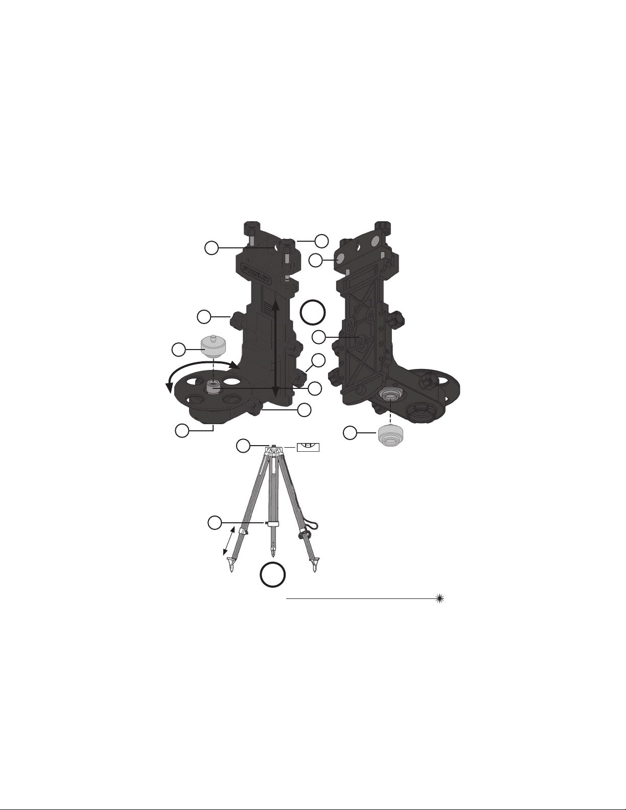
Product Overview
Figure A - Laser Tool in Horizontal Position
1. Alignment Sight
2. Vertical Up Beam Window (RL HV / RL HVPW)/RL
HVPW-G
3. Rotary Laser / Glass Enclosed
4. Charging / Power Adapter Plug Jack
5. Keypad (See Figure E)
6. Vertical Down Beam (RL HVPW/RL HVPW-G)
7. Infrared Sensor for Remote
(RL HW+ / RL HGW / RL HV / RL HVPW/RL HVPW-G)
Figure B - Laser Tool in Vertical Position
Figure C - Laser Tool with Sighting Telescope Accessory
(RL HGW)
8. Sighting Telescope
9. Sighting Telescope Mount Base
Figure D - Sighting Telescope
10. Eyepiece (Shown with Cover ON)
11. Reticle Focus
12. Windage / Elevation Adjustment Covers
(DO NOT OPEN / ADJUST)
13. Locking Screws
14. Objective (Shown with Cover ON)
Figure E - Keypad Configurations
IEC/EN 60825-1
LAS ER R AD IA TI ON - D O NO T
STA RE I NT O TH E BE AM
CLA SS 2 L AS ER P RO DU CT
Max Out put ≤ 1 m W @ 630 - 670 nm
Page 9
9
77-496 / 77-429 / 77-439 / 77-497 / 77-427 / 77-441
Figure F - Laser Tool Battery Location
15. Battery Pack
16. Optional Batteries - 4 x “C”
17. Battery Cartridge for use with 4 x “C” Batteries
Figure G - Remote Control
18. Infrared LED
19. Keypad
Figure H - Remote Control Battery Location
20. Batteries - 2 x “AAA”
21. Battery Compartment
Figure J - Bracket Accessory
22. Key Hole Slot for Wall Hanging
23. Ceiling Grid Clamp
24. Vertical (Up / Down) Fine Adjust Knob
25. Included 5/8 to 1/4 Adapter
26. Vertical Adjust Lock Knob
27. 5/8 Mounting Screw
28. Rotary Fine Adjust Knob
29. Tightening Knob
30. Magnetic Mount
31. Keyhole Mount for Additional Magnet and / or Clamp
Accessories
32. Storage Location for 5/8 to 1/4 Adapter
Figure K - Tripod Mounting
33. 5/8 Center Screw
34. Leg Lock Lever
Figure L - Calibration and / or Slope Axis Direction
Figure M - Spot and / or Scan Rotation Direction
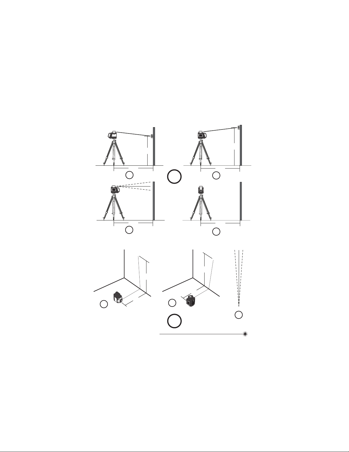
Figure N - Horizontal Check Setup
Figure P - Vertical Check Setup
RL HW RL HW+ RL HGW RL HV
RL
HVPW/-G
Horizontal Auto-Levelling X X X X X
Tilt Warning X X X X X
Manual Mode X X X X X
Calibration Mode X X X X X
IR sensor for remote X X X X
Vertical Auto-Levelling X X X X
Manual Slope Mode (NO Auto-Levelling) X X X X
Speed Select X X X
Spot Mode X X X
Scan Mode X X
Vertical Up Beam X X
Vertical Down Beam X
Digital Slope Mode (with Auto-Levelling) X
Feature Set
Page 10
10
77-496 / 77-429 / 77-439 / 77-497 / 77-427 / 77-441
Keypad, LED, and LCD
(See figure E to reference keypad display for each
laser tool model)
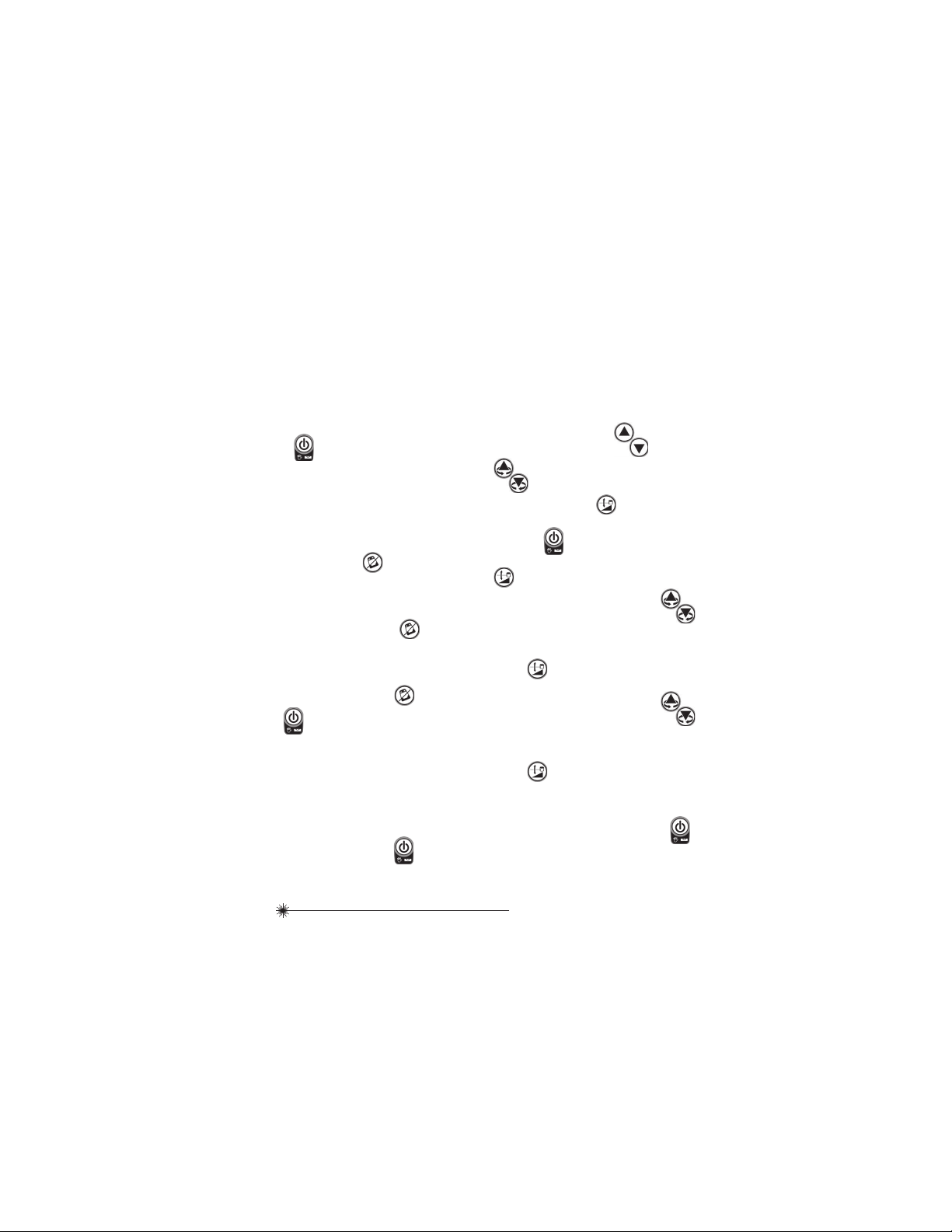
Keypads
RL HW (See Figure
E
1
)
Power ON / OFF Key
Tilt Warning ON / OFF Key
Calibration Mode Key
Calibration Adjust Keys
RL HW+ (See Figure
E
2
)
Power ON / OFF Key
Tilt Warning ON / OFF Key
Manual Slope Mode Key
Calibration Adjust Keys
RL HV / RL HVPW /RLHVPW-G(See Figure
E
3
)
Power ON / OFF Key
Tilt Warning ON / OFF Key
Rotation Speed Key
Scan Mode Key
Manual Slope Mode Key
Scan, Spot, Slope and Calibration Adjust
Keys
RL HGW (See Figure
E
4
)
Power ON / OFF Key
Tilt Warning ON / OFF Key
Rotation Speed Key
Auto-Levelling / Manual Slope Mode Key
Scan, Spot, Slope and Calibration Adjust
Keys
Page 11
11
77-496 / 77-429 / 77-439 / 77-497 / 77-427 / 77-441
LEDs
Power LED - Blinking GREEN
• Laser Tool is Auto-Levelling
• In Calibration and / or Default Tilt Warning
Set Up
Power LED - Solid GREEN
• Auto-Levelling Complete
Power LED - Blinking RED
• Low Battery
Power LED - Solid RED
• Battery Needs Recharging
Manual LED - Blinking RED
• Manual Mode ON (Auto-Levelling OFF)
Manual LED - Blinking RED
with
Power LED - Blinking GREEN
• Out of Compensation Range
Tilt Warning LED - Solid RED
• Tilt Warning ON
Tilt Warning LED - Blinking RED
• Tilt Warning Alarm
X / Y Select LED - Solid GREEN
• X Axis Adjust Slope Mode
X / Y Select LED - Solid RED
• Y Axis Adjust Slope Mode
X / Y Select LED - Blinking GREEN
• X Axis at Maximum Allowed Slope in Slope
Mode
• X axis adjust Calibration Mode
X / Y Select LED - Blinking RED
• Y Axis at Maximum Allowed Slope in Slope
Mode
• Y axis adjust Calibration Mode
LCD Icons
Auto-Levelling Icon - Blinking
• Laser Tool is Auto-Levelling
• In Calibration and / or Default Tilt Warning
Set Up
Manual Icon - Blinking
• Manual Mode ON (Auto-Levelling OFF)
Warning Icon - Blinking
• Out of Compensation Range
• Bumped while Auto-Sloping
Tilt Icon - Solid
• Tilt Warning ON
Tilt Icon - Blinking
• Tilt Warning Alarm
Slope Icon - Solid
• Slope Mode ON
Slope Icon - Blinking
• At Maximum Allowed Slope
Calibration Icon - Solid
• Calibration Mode ON - Horizontal
Calibration Icon - Blinking
• Calibration Mode ON - Vertical
Rotation Icon with Speed Value
• Speed Setting
X / Y Icon Only - Blinking
• Adjust Shown Axis in Manual Slope and / or
Calibration Mode
X / Y Icon with Value - Value Blinking
• Adjust Shown Value in Auto-Levelling Slope
Mode
Vertical Position Icon - Solid
• Shown when Laser Tool is in Vertical Position
Battery Power - Solid
• Approximate Battery Life as Shown
Battery Power - Blinking
• Battery Needs Recharging
Page 12
12
77-496 / 77-429 / 77-439 / 77-497 / 77-427 / 77-441
Batteries and Power
Battery Installation / Removal
(See figure F and G to reference battery location of
laser tool and remote control)
Laser Tool (See figure
F
)
• Press tabs to open battery compartment and slide out.
• Install / Remove batteries. Orient batteries correctly
when placing into laser tool.
• Securely close and lock battery compartment cover.
IR Remote Controller (See figure
G
)
• Open battery compartment by sliding cover off.
• Install / Remove batteries. Orient batteries correctly
when placing into laser tool.
• Securely close and lock battery compartment cover.
WARNING:
• Pay close attention to the battery holder’s (+)
and (-) markings for proper battery insertion.
Batteries must be of same type and capacity. Do
not use a combination of batteries with different
capacities remaining.
Charging Battery
• For best life, the rechargeable battery must be charged for
4 hours before first use.
• Plug charging / power adapter plug into charging jack of
laser tool
• Plug charging / power adapter into power outlet (110 V or
220 V) with appropriate plug receptacle.
• The LED on the charging / power adapter will light RED
during charge.
• Leave battery to charge for approximately 4 hours to reach
full charge.
• When battery is fully charged unplug the charging / power
adapter from laser tool and power outlet.
• The LED on the charging / power adapter will light GREEN
when charge is complete.
WARNING:
• Use charging / power adapter only with Ni-MH
battery pack supplied. Charging any other
type of battery may result in damage and/or
personal harm.
WARNING:
• The battery and charging / power adapter can be
damaged if damp. Always store and charge the
tool in a dry and covered place.
NOTE:
• For best battery life, it is recommended to charge the
battery once it has been fully discharged and avoid letting
charge for > 10 hours at a time.
Operating with Charging / Power
Adapter
• Laser tool can operate while plugged into charging / power
adapter.
• Functions and controls of laser tool are the same as when
not plugged into charging / power adapter.
Set Up
Positioning
(See Feature Set to reference which models offer AutoLevelling in the given positions)
Horizontal Position (See figure A)
• Place laser tool down on its bottom. Be sure surface is
near level. Press
to power ON.
Vertical Position (See figure B)
• Place laser tool down on its side, handle facing up. Be
sure surface is near level. Press
to power ON.
Page 13
13
77-496 / 77-429 / 77-439 / 77-497 / 77-427 / 77-441
At Angle
• Press
to power ON. Press and hold to turn
ON Manual Mode. Laser tool can now be positioned to
various angles with auto-levelling mode OFF.
NOTE:
• To change between horizontal and vertical positions the
laser tool must be powered OFF, repositioned, and then
powered ON in the new position.
Mounting on Accessories
Mounting Bracket (See figure J)
• Securely position wall bracket in a location to be
measured.
• Visually orient the bracket mounting surface so that it is
near horizontal.
• Mount the laser tool to the bracket and tighten the
tightening knob.
Tripod Mount (See figure K)
• Position a tripod in a place where it will not be easily
disturbed and near the central location of the area to
be measured.
• Extend tripod legs as required. Adjust leg positioning to
be sure tripod head is near horizontal.
• Mount the laser tool to the tripod by pushing up the 5/8
center screw and tighten.
CAUTION:
• Do not leave the laser tool unattended on an
accessory without fully tightening the center
screw. Failing to do so may lead to the laser tool
falling and sustaining possible damage.
NOTE:
• Either dome head, flat head or elevator type tripod can be
used with the laser tool.
• It is best practice to always support laser tool with
one hand when placing or removing laser tool from an
accessory.
• If positioning over a target, partially tighten the 5/8 screw
mount, align laser tool, and then fully tighten the 5/8
screw mount.
Sighting Telescope (RL HGW)
(The Alignment Sight on the top cover of the laser tool
can be used for models that do not include the Sighting
Telescope)
Mounting and Use (See figure
C
)
• Loosen both locking screws on sighting telescope. Guide
scope onto the mount base located on top of the laser
tool with the objective (smaller end) towards the target (
C
1
). Securely tighten the locking screws (
C
2
).
• Remove the lens covers from the scope and roughly aim
the laser tool / scope towards the target.
• Look through the eyepiece (larger end) and turn the
reticle focus until the reticle (cross hair) is sharp and
clearly visible.
• Look through the eyepiece to align the vertical line of the
reticle with target. Adjust the distance between the eye
and eyepiece to focus the target.
NOTE:
• Use of the alignment sight / sighting telescope is to
accurately align and square the laser tool to a target when
setting a slope for grade applications.
• The sighting telescope has been sighted-in by the
manufacturer and should not require any additional
adjustments. DO NOT attempt to adjust the windage and
elevation of the sighting telescope. Doing so may cause
inaccuracies in sighting the target and alignment of the
laser tool.
Operation
NOTE:
• See Feature Set to reference which models offer specific
functions / modes.
• See LCD / LED Descriptions for indications during
operation.
• Before operating the laser tool always be sure to check the
laser tool for accuracy.
• In Manual Mode, Auto-Levelling is OFF. The accuracy of the
beam is not guaranteed to be level.
• Laser tool will indicate when it is out of compensation
range. Reference LED / LCD Descriptions. Reposition
laser tool to be closer to level.
• When not in use, please be sure to power OFF the laser
tool.
• Because the laser tool is an instrument with high precision,
Page 14
14
77-496 / 77-429 / 77-439 / 77-497 / 77-427 / 77-441
it is preferable to use the remote whenever possible to
perform functions (when available).
• Laser tool is Auto-Levelling by default.
• Tilt Warning is ON by default when laser tool leaves the
manufacturer.
• Tilt Warning is only available in the Auto-Levelling modes.
Tilt Warning is not available while in Manual Mode.
Power
• Press
to turn laser tool ON / OFF.
• When powered ON, Tilt Warning is ON by default
(default setting can be changed).
• When powered ON, Laser tool begins Auto-Levelling.
• When Auto-Levelling has completed laser will rotate at
last used RPM speed setting.
Tilt Warning (not available in Manual Mode)
• When powered ON, Tilt Warning is ON by default.
• When powered ON, press
to turn Tilt Warning
ON / OFF.
• With Tilt Warning ON, laser tool will indicate with LED
/ LCD and blinking laser beam when the laser tool has
sensed any movement.
• If an alarm has been triggered, press
to reset.
• When reset, the laser tool begins Auto-Levelling. Check
alignment with original target.
Tilt Warning Default Setting
• When powered OFF, press and hold
followed
by
.
• Release both keys.
• If Tilt LED / Icon is ON, default setting is ON. If Tilt LED /
Icon is OFF default setting is OFF.
• Laser tool begins Auto-Levelling as done when normally
powered ON.
• Repeating the steps will toggle ON / OFF the Tilt
Warning default setting.
Manual Mode
• When powered ON, press and hold
for ≥ 3
seconds to turn ON / OFF Manual Mode.
• Auto-Levelling is OFF in Manual Mode.
• Laser tool can be manually positioned at any angle.
• When Manual Mode is turned OFF, laser tool begins
Auto-Levelling as done when initially powered ON.
Calibration Mode - see Accuracy Check and
Calibration section
Manual Slope Mode
(For RL HW / RL HW+ substitute where ever
is referenced below)
• When powered ON, press
. Manual Mode turns
ON, Auto-Levelling OFF.
(For RL HGW
needs to be pressed and held for
≥ 3 seconds to enter Manual Mode prior to pressing
noted above)
• LED / LCD will indicate “X” axis adjust. Press
to adjust axis.
• LED / LCD will indicate when at maximum slope angle.
The axis will not move any further in that direction.
• Press
again to set the “X” axis and / or proceed to
the “Y” axis adjust.
• LED / LCD will indicate “Y” axis adjust. Press
to adjust axis.
• LED / LCD will indicate when at maximum slope angle.
The axis will not move any further in that direction.
• Press
again to set the “Y” axis and / or proceed to
use of laser tool in Manual Slope Mode.
• “X” and “Y” axis are now set at manually adjusted
slopes.
• To turn Manual Slope Mode OFF, press and hold
for ≥ 3 seconds.
• When Manual Mode is turned OFF, laser tool begins
Auto-Levelling as done when initially powered ON.
Page 15
15
77-496 / 77-429 / 77-439 / 77-497 / 77-427 / 77-441
NOTE:
• A single press of
will change slope by 0,01%.
• Holding the key down will move the slope axis
continuously, slowly at first, followed by a faster rate
when held for an extended time.
• Reference Figure L for resulting slope direction for
each key.
Speed
• Press
to toggle through the available speed
settings from fastest to slowest to stopped.
Spot Mode
• Press
to stopped (0 RPM) setting.
• Press
to rotate the direction of the spot.
NOTE:
• A single press of
will rotate the direction
by 0,10°.
• Holding down the key will rotate the direction
continuously, slowly at first, followed by a faster rate
when held for an extended time.
• The laser will blink 3 x prior to moving at the faster rate.
• Reference Figure
M
for resulting rotation direction
for each key.
Scan Mode
• Press
to cycle through available scan angles (15°
/ 45° / 90°).
• Press
to rotate the direction of the scan.
• Press
to turn OFF Scan Mode and return to the last
used speed setting.
NOTE:
• A single press of
will rotate the direction
by 2,0°.
• Holding down the key will rotate the direction
continuously, slowly at first, followed by a faster rate
when held for an extended time.
• The laser will blink 3 x prior to moving at the faster rate.
• Reference Figure
M
for resulting rotation direction
for each key.
Digital Slope Mode (with Auto-Levelling)
• When powered ON, press
.
• LCD will indicate “X” axis adjust. Press
to
adjust axis value.
• LCD will indicate when at maximum slope angle. The
value will not continue any further in that direction.
• Press
again to set the “X” axis and / or proceed to
the “Y” axis value adjust.
• LCD will indicate “Y” axis adjust. Press
to
adjust axis value.
• LCD will indicate when at maximum slope angle. The
value will not continue any further in that direction.
• Press
again to set the “Y” axis and / or proceed to
use of laser tool in Digital Slope Mode.
• Laser tool begins Auto-Levelling as done when initially
powered ON and then the “X” and “Y” axis will slope to
the set values.
• To turn Digital Slope Mode OFF, the laser tool power
needs to be cycled. Press
2x to power OFF and
back ON.
NOTE:
• A single press of
will change the value by
0,01%.
• Holding the key down will move the value continuously,
slowly at first, followed by a faster rate when held for
an extended time.
Page 16
16
77-496 / 77-429 / 77-439 / 77-497 / 77-427 / 77-441
• There is no need to adjust calibration if the distance
between reference point “D
1
” and “D2” is < 2,0 mm.
• If the distance measured is ≥ 2,0 mm then a calibration
adjustment is necessary.
• Perform the same steps for the “Y” axis as was done
for the “X” axis. Replace “X1” and “X2” with Y1” and
“Y2” (
N
4
).
Horizontal Calibration (See Figure
N
)
(For RL HW substitute
where ever is
referenced below)
(For RL HW / RL HW+ substitute where ever
is referenced below)
• With laser tool powered OFF, press and hold
followed by
.
• Release
and continue to hold for ≥ 3
seconds.
• Release
.
• The LED/LCD will indicate laser tool is in Calibration
mode.
• If necessary, adjust the “X” axis by pressing
until the laser beam is aligned with “D0”. “D0” is the
halfway point between “D
1
” and “D2” during “X” axis
check.
• Press
again to set the “X” axis and / or proceed to
the “Y” axis adjust.
• If necessary, adjust the “Y” axis by pressing
until the laser beam is aligned with “D0”. “D0” is the
halfway point between “D
1
” and “D2” during “Y” axis
check.
• Press
again to set the “X” axis and / or proceed to
• Reference Figure L for resulting slope direction for
each key.
Remote Control
• The same functions / modes for each specific laser tool
are accessible through use with the keys available on
the remote.
• The laser tool can be powered OFF with the remote by
pressing both
at the same time. The laser tool
can only be powered ON with the power key on the
laser tool.
Accuracy Check and
Calibration
NOTE:
• See Feature Set to reference which models offer specific
functions.
• The laser tools are sealed and calibrated at the factory to
the accuracies specified.
• It is recommended to perform a calibration check prior to
its first use and then periodically during future use.
• Be sure to allow the laser tool adequate time to Auto-Level
(< 60 seconds) prior to a calibration check.
• The laser tool should be checked regularly to ensure its
accuracies, especially for precise layouts.
Horizontal Check (See Figure
N
)
• Set the laser tool on a tripod 20 m away from a wall
with the ”X1” side facing the wall (
N
1
).
• Power ON the laser tool and allow the laser tool to
Auto-Level and be sure laser is rotating.
• Go to the wall and mark a reference point “D
1
” where
the laser line is on the wall. If available, using a
detector may help in locating the beam more easily.
• Loosen the laser tool from the tripod and rotate the
laser tool 180° so that the “X2” side is now facing the
wall (
N
2
).
• Go back to the wall and measure the distance between
the first reference point “D
1
” and the second reference
point “D
2
” (
N
3
).
Page 17
17
77-496 / 77-429 / 77-439 / 77-497 / 77-427 / 77-441
exit Calibration Mode.
• Axis settings are now saved, Calibration Mode is OFF,
and laser tool begins Auto-Levelling as done when
initially powered ON.
NOTE:
• A press of
will slope the axis by 3,5 arc
seconds. Reference Figure
L
for resulting slope direction
for each key.
• If the laser tool can still not be calibrated after
following the Calibration procedure, please send
the laser tool into an Authorized Service Center for
repair.
Vertical Check (See Figure
P
)
(Only necessary on models with Vertical Auto-Levelling)
• Set the laser tool on a stable surface in its vertical
position 1 m away from a wall that extends ≥ 2 m high
with the ”Y1” side facing that wall (
P
1
).
• Power ON the laser tool and allow the laser tool to
Auto-Level and be sure laser is rotating.
• Mark reference points “A” (where laser line is on
floor 1 m away from wall), “B “ (where laser beam
is at corner), and “D1” (where laser beam is 2 m
up the wall).
• Rotate the laser tool 180° so that the “Y2” side is now
facing the wall (
P
2
).
• Align the laser beam with reference points “A” and “B”
and then go back to the wall and measure the distance
between the reference point “D
1
” and “D2” (
P
3
).
• There is no need to adjust calibration if the distance
between reference point “D
1
” and “D2” is < 1,0 mm.
• If the distance measured is ≥ 1,0 mm then a calibration
adjustment is necessary.
Vertical Calibration (See Figure
P
)
(For RL HW+ substitute
where ever is
referenced below)
• With laser tool powered OFF, press and hold
followed by
.
• Release and continue to hold for ≥ 3
seconds.
• Release
.
• The LED/LCD will indicate laser tool is in Calibration
mode.
• If necessary, adjust the vertical “X” axis by pressing
until the laser beam is aligned with “D0”.
“D
0
” is the halfway point between “D
1
” and “D2”
during vertical axis check.
• .
• Press
to set the vertical “X” axis.
• Axis setting is now saved, Calibration Mode is OFF,
and laser tool begins Auto-Levelling as done when
initially powered ON.
NOTE:
• A press of
will slope the axis by 3,5 arc
seconds. Reference Figure L for resulting slope direction
for each key.
• If the laser tool can still not be calibrated after
following the Calibration procedure, please send
the laser tool into an Authorized Service Center for
repair.
Page 18

18
77-496 / 77-429 / 77-439 / 77-497 / 77-427 / 77-441
Specifications
Laser Tool
RL HWRL
HW+
RL HGW RL HV
RL
HVPW
RL HVPW-G
Horizontal Rotary
Accuracy:
±1.5 mm/30 m (±10”)
Vertical Rotary Accuracy: ±3 mm/30 m (±20”)
Vertical Up Beam
Accuracy:
±3 mm/30 m (±20”)
Vertical Down Beam
Accuracy:
±9 mm/30 m (±60”)
Slope Accuracy: +/-15mm/30m (+/-100”)
Compensation Range: ≥ 5°±1° (dual axis)
Slope Range: ±10% (dual axis)
Minimum Increment: 0,01%
Scan Range: 10°/45°/90° ±20%
Working Range Diameter
with Detector:
≤ 600 m
Leveling Time ≤ 20 seconds
Rotation Speed: 600 rpm ±10%
1000/600/300/150/0
rpm ±10%
600/300/150/0 rpm ±10%
Laser Class: Class 2 (IEC/EN 60825-1)
Class 3R (IEC/
EN60825-1)
Laser Wavelength: 635 nm 515-540nm
Operating Time: ≥ 20 hours (Ni-MH) ≥ 12 hours(Ni-MH)
Recharge Time: ≤ 4 hours
Power Source: NI-MH Battery Pack
IP Rating: IP66
Operating Temperature
Range:
-10° C ~ +50° C
Storage Temperature
Range:
-25° C ~ +70° C
Page 19

19
77-496 / 77-429 / 77-439 / 77-497 / 77-427 / 77-441
Remote Controller
Infrared
40 m
2 x AAA Batteries (Alkaline)
Type:
Indoor Operating Range:
Power Source:
Sighting Telescope
2,5 x
5° 36’
8 mm
32 mm
≤ 8°
85 mm
Magnification:
Field of View:
Visual Diameter:
Objective Diameter:
Resolving Power:
Eye Relief:
Notes
Page 20

20
77-496 / 77-429 / 77-439 / 77-497 / 77-427 / 77-441
WARNUNG:
• Die folgenden Beispiele für Etiketten sind
auf Ihrem Lasergerät angebracht, um Sie zu
Ihrer Annehmlichkeit und Sicherheit über die
Laserklasse zu informieren. Bitte wenden Sie
sich an das Produkthandbuch bezüglich
der technischen Daten eines speziellen
Produktmodells.
IEC/EN 60825-1
LASERSTRAHLUNG - NICHT IN DEN
STRAHL BETRACHTEN
LASERPRODUKT DER KLASSE 2
Maximale Leistung ≤ 1 mW @ 630 - 670 nm
Inhaltsverzeichnis
• Sicherheit
• Produktüberblick
• Funktionsumfang
• Tastatur, LED-Anzeige und LCD
• Batterien und Stromversorgung
• Konfiguration
• Bedienung
• Genauigkeitsprüfung und Kalibrierung
• Technische Daten
Produktüberblick
Abbildung A - Lasergerät in horizontaler Position
1. Ausrichtung Sichtweite
2. Fenster für vertikalen Aufwärtsstrahl (RL HV / RL
HVPW/ RL HVPW -G)
3. Rotationslaser / Glasgehäuse
4. Aufladung / Stromadapterstecker
5. Tastatur (Siehe Abbildung
E
)
6. Vertikaler Abwärtsstrahl (RL HVPW / RL HVPW -G)
Abbildung B - Lasergerät in vertikaler Position
Abbildung C - Lasergerät mit Zielfernrohr (RL HGW)
7. Infrarotsensor für Fernbedienung
8. Zielfernrohr
9. Zielfernrohr Aufsatzteil
Abbildung D - Zielfernrohr
10. Sucher (Dargestellt mit aufgesetzter Abdeckung)
11. Fadenkreuz
12. Abdeckungen für Seiten- / Höhenanpassung
(NICHT ÖFFNEN / MODIFIZIEREN)
13. Verschlussschrauben
14. Objektiv (Dargestellt mit aufgesetzter Abdeckung)
Abbildung E - Konfigurationen des Tastenfelds
Abbildung F - Batteriefach im Lasergerät
15. Batteriesatz
16. Geeignete Batterien - 4 x “C”
17. Batteriefach zur Verwendung mit 4 x "C"-Batterien
Benutzersicherheit
WARNUNG:
• Lesen Sie vor Verwendung des Produkts
aufmerksam die Sicherheitsanweisungen und
das Produkthandbuch. Die für das Instrument
verantwortliche Person muss gewährleisten,
dass sämtliche Benutzer die darin enthaltenen
Anweisungen verstehen und befolgen.
ACHTUNG:
• Während das Lasergerät in Betrieb ist, seien
Sie vorsichtig, dass Ihre Augen nicht dem
austretenden Laserstrahl ausgesetzt werden
(rote Lichtquelle). Wenn Ihre Augen dem
Laserstrahl für längere Zeit ausgesetzt sind, kann
das für Ihre Augen gefährlich sein.
ACHTUNG:
• In einigen Ausrüstungssets der Laser sind
Schutzbrillen beigefügt. Diese sind NICHT
als Sicherheitsbrillen zertifziert. Diese Brillen
werden NUR verwendet, um die Sicht auf
den Strahl in helleren Umgebungen oder bei
größeren Entfernungen zur Laserquelle zu
verbessern.
Bewahren Sie alle Abschnitte des Handbuchs auf, um in
Zukunft darauf jederzeit Zugriff zu haben.
D
Page 21

21
77-496 / 77-429 / 77-439 / 77-497 / 77-427 / 77-441
Abbildung G - Fernbedienung
18. Infrarot-LED
19. Tastenfeld
Abbildung H - Batteriefach der Fernbedienung
20. Batterien - 2 x "AAA"
21. Batteriefach
Abbildung J - Zubehörhalterung
22. Schlüssellochschlitz für Wandaufhängung
23. Deckengitterklammer
24. Knauf zur (Aufwärts- / Abwärts-) vertikalen Feinjustierung
25. Einschließlich 5/8- bis 1/4-Adapter
26. Knauf zur vertikalen Einstellsperre
27. 5/8-Aufsatzschraube
28. Knauf zur Feinjustierung der Rotation
29. Knauf zum Festziehen
30. Magnethalterung
31. Schlüssellochaufsatz für zusätzliches Magnet- und / oder
Klammerzubehör
32. Aufbewahrungsort des 5/8- bis 1/4-Adapters.
Abbildung K - Stativaufsatz
33. Zentrale 5/8-Schraube
34. Beinverriegelungshebel
Abbildung L - Kalibrierung und / oder Neigungsachsen-
ausrichtung
Abbildung M - Punkt- und / oder Abtastrotationsaus-
richtung
Abbildung N - Horizontale Prüfungskonfiguration
Abbildung P - Vertikale Prüfungskonfiguration
RL HW RL HW+ RL HGW RL HV
RL
HVPW/-G
Horizontale automatische Nivellierung X X X X X
Verkippungswarnung X X X X X
Manueller Modus X X X X X
Kalibrierungsmodus X X X X X
IR-Sensor für Fernbedienung X X X X
Vertikale automatische Nivellierung X X X X
Manueller Neigungsmodus (OHNE automatische
Nivellierung)
X X X X
Auswahl Geschwindigkeit X X X
Punktmodus X X X
Abtastmodus X X
Vertikaler Aufwärtsstrahl X X
Vertikaler Abwärtsstrahl X
Digitaler Neigungsmodus (mit automatischer
Nivellierung)
X
Funktionsumfang
Page 22

22
77-496 / 77-429 / 77-439 / 77-497 / 77-427 / 77-441
Tastatur, LED-Anzeige und
LCD
(Siehe Abbildung E bezüglich der Nutzung der
Tastaturanzeige für jedes Laser-Modell)
Tastenfelder
(RL HW+
E
2
)
Ein-/Ausschalttaste
Neigungswarnungstaste EIN / AUS
Taste manueller Neigungsmodus
Tasten zur Neigungs- und Kalibrierungsanpassung
(RL HGW
E
4
)
Ein-/Ausschalttaste
Neigungswarnungstaste EIN / AUS
Taste Rotationsgeschwindigkeit
Taste zur automatischen Nivellierung /
manueller Neigungsmodus
Tasten zur Punkt-, Neigungs- und
Kalibrierungsanpassung
(RL HV / RL HVPW / RL HVPW -G
E
3
)
Ein-/Ausschalttaste
Neigungswarnungstaste EIN / AUS
Taste Rotationsgeschwindigkeit
Abtastmodustaste
Taste manueller Neigungsmodus
Tasten zur Abtastungs-, Punkt-, Neigungs- und Kalibrierungsanpassung
(RL HW
E
1
)
Ein-/Ausschalttaste
Neigungswarnungstaste EIN / AUS
Kalibrierungsmodustaste
Kalibrierungsanpassungstaste
Page 23

23
77-496 / 77-429 / 77-439 / 77-497 / 77-427 / 77-441
LEDs
Power LED - Blinkt GRÜN
• Der Laser nivelliert sich automatisch
• Bei der Kalibrierung und / oder der Einrichtung der Standardneigungswarnung
Power LED - Leuchtet GRÜN
• Automatische Nivellierung abgeschlossen
Power LED - Blinkt ROT
• Batterie fast leer
Power LED - Leuchtet ROT
• Die Batterien müssen neu aufgeladen
werden
Manuell-LED - Blinkt ROT
• Manueller Modus EIN (Automatische
Nivellierung AUS)
Manuell-LED - Blinkt ROT
mit
Power LED - Blinkt GRÜN
• Außerhalb des Ausgleichsbereichs
Neigungswarnungs-LED - Leuchtet ROT
• Neigungswarnung EIN
Neigungswarnungs-LED - Blinkt ROT
• Neigungswarnungsalarm
X / Y-Auswahl-LED - Leuchtet GRÜN
• X-Achsenanpassung Neigungsmodus
X / Y-Auswahl-LED - Leuchtet ROT
• Y-Achsenanpassung Neigungsmodus
X / Y-Auswahl-LED - Blinkt GRÜN
• X-Achse bei maximal zulässiger Neigung im
Neigungsmodus
• X-Achsenanpassung Kalibrierungsmodus
X / Y-Auswahl-LED - Blinkt ROT
• Y-Achse bei maximal zulässiger Neigung im
Neigungsmodus
• Y-Achsenanpassung Kalibrierungsmodus
LCD-Symbole
Symbol automatische Nivellierung - Blinkt
• Der Laser nivelliert sich automatisch
• Bei der Kalibrierung und / oder der Einrichtung der Standardneigungswarnung
Symbol manuell - Blinkt
• Manueller Modus EIN (Automatische
Nivellierung AUS)
Symbol Warnung - Blinkt
• Außerhalb des Ausgleichsbereichs
• Zusammenstoß während der automatischen
Neigungseinstellung
Symbol Verkippung - Leuchtet
• Neigungswarnung EIN
Symbol Verkippung - Blinkt
• Neigungswarnungsalarm
Symbol Neigung - Leuchtet
• Neigungsmodus EIN
Symbol Neigung - Blinkt
• Bei maximal zulässiger Neigung
Symbol Kalibrierung - Leuchtet
• Kalibrierungsmodus EIN - Horizontal
Symbol Kalibrierung - Blinkt
• Kalibrierungsmodus EIN - Vertikal
Symbol Rotation mit Geschwindigkeitsangabe
• Geschwindigkeitseinstellung
Nur X / Y Symbol - Blinkt
• Anpassung angezeigte Achse in manueller
Neigung und / oder Kalibrierungsmodus
X / Y Symbol mit Angabe - Angabe blinkt
• Anpassung des angzeigten Werts im Neigungsmodus mit automatischer Nivellierung
Batterieleistung - Leuchtet
• Ungefähre Batterielebensdauer wie
angezeigt
Batterieleistung - Blinkt
• Die Batterien müssen neu aufgeladen
werden
Symbol Vertikale Position - Leuchtet
• Wird angezeigt, wenn das Lasergerät sich in
vertikaler Position befindet
Page 24

24
77-496 / 77-429 / 77-439 / 77-497 / 77-427 / 77-441
Batterien und
Stromversorgung
Einlegen / Entfernen der Batterien
(Siehe Abbildung F und G zum Zugriff auf die
Batterien des Lasergeräts und Fernsteuerung)
• Drücken Sie auf den Verschluss, um das Batteriefach zu
öffnen und diese zu entnehmen.
• Batterien einlegen / entfernen. Batterien beim Einlegen
in das Lasergerät ordnungsgemäß ausrichten.
• Batteriefachabdeckung sicher schließen und verriegeln.
Lasergerät (Siehe Abbildung
F
)
IR-Fernbedienung (Siehe Abbildung
G
)
• Öffnen Sie das Batteriefach, indem Sie die Abdeckung
wegschieben.
• Batterien einlegen / entfernen. Batterien beim Einlegen
in das Lasergerät ordnungsgemäß ausrichten.
• Batteriefachabdeckung sicher schließen und verriegeln.
WARNUNG:
• Achten Sie besonders auf die Markierungen
(+) und (-) der Batterien, so dass diese richtig
eingelegt sind. Die Batterien müssen vom
gleichen Typ sein und die gleiche Spannung
aufweisen. Verwenden Sie keine kombinierten
Batterien mit unterschiedlichen Restladungen.
Batterien aufladen
• Für die größtmögliche Lebensdauer müssen die
wiederaufladbaren Batterien vor dem ersten Gebrauch für 4
Stunden aufgeladen werden.
• Stecken Sie das Ladegerät / den Adapter in die Buchse
des Lasergeräts.
• Verbinden Sie das Ladegerät / den Adapter mit einem
Stromanschluss (110 V oder 220 V) mit einer passenden
Steckdose.
• Die LED auf dem Ladegerät / dem Adapter leuchtet ROT
während des Ladevorgangs.
• Lassen Sie die Batterie für ungefähr 4 Stunden aufladen,
um eine volle Aufladung zu erreichen.
• Sobald die Batterien voll aufgeladen sind, trennen Sie
das Ladegerät / den Adapter vom Lasergerät und von der
Steckdose.
• Die LED auf dem Ladegerät / dem Adapter leuchtet GRÜN,
wenn die Aufladung abgeschlossen ist.
WARNUNG:
• Verwenden Sie das Ladegerät / den Adapter
nur zusammen mit dem mitgelieferten Satz NiMH-Batterien. Beim Laden von Batterien eines
anderen Typs kann dies zu Schäden und/oder
Verletzungen führen.
WARNUNG:
• Die Batterien und das Ladegerät / der Adapter
können Schaden nehmen, wenn Sie Dampf
ausgesetzt werden. Lagern und laden Sie das
Gerät stets an einem trockenen und geschützten
Ort.
HINWEIS:
• Für die größtmögliche Lebensdauer der Batterien wird
empfohlen, die Batterien zu laden, sobald sie vollständig
entladen sind und sie nicht länger als > 10 Stunden
aufzuladen.
Betrieb mit dem Ladegerät /
Stromadapter
• Das Lasergerät kann betrieben werden, während es an das
Ladegerät / den Stromadapter angeschlossen ist.
• Funktionen und die Steuerung des Lasergeräts sind
dieselben, wie wenn es nicht am Ladegerät / am
Stromadapter angeschlossen ist.
Konfiguration
Positionierung
(Siehe Funktionsumfang der einzelnen Modelle
und welche automatische Nivellierung sie in den
vorgegebenen Positionen bieten)
Horizontale Position (Siehe Abbildung
A
)
• Stellen Sie das Lasergerät auf seine Unterseite. Stellen
Sie sicher, dass der Laser auf "Nah" eingestellt ist.
Drücken Sie
um das Gerät EIN zu schalten.
Page 25

25
77-496 / 77-429 / 77-439 / 77-497 / 77-427 / 77-441
Vertikale Position (Siehe Abbildung B)
• Stellen Sie das Lasergerät auf seine Seite, mit dem
Griff nach oben. Stellen Sie sicher, dass der Laser auf
"Nah" eingestellt ist. Drücken Sie
um das Gerät
EIN zu schalten.
Angewinkelt
• Drücken Sie
um das Gerät EIN zu schalten.
Drücken Sie und halten Sie
gedrückt, um den
manuellen Modus EIN zu schalten. Das Lasergerät kann
nun in verschiedenen Winkeln positioniert werden,
wobei der automatische Nivellierungsmodus AUS
geschaltet ist.
HINWEIS:
• Um zwischen horizontalen und vertikalen Positionen zu
wechseln, muss das Lasergerät AUS geschaltet, neu
positioniert und dann in der neuen Position wieder EIN
geschaltet werden.
Aufsetzen auf das Zubehör
Montagebügel (Siehe Abbildung J)
• Positionieren Sie die Wandhalterung sicher an einem
Ort, der ausgemessen werden soll.
• Orientieren Sie die Aufsatzfläche der Halterung nach
Augenmaß so, dass sie nahezu horizontal ausgerichtet
ist.
• Setzen Sie das Lasergerät auf die Halterung und ziehen
Sie den Befestigungsknauf fest.
Stativaufsatz (Siehe Abbildung
K
)
• Positionieren Sie ein Stativ an einem Ort, an dem
keine Störungen vorhanden sind und in der Nähe des
Zentrums des Bereichs, der vermessen werden soll.
• Ziehen Sie die Beine des Stativs aus wie erforderlich.
Passen Sie die Position der Beine so an, um
sicherzustellen, dass der Stativkopf nahezu horizontal
ausgerichtet ist.
• Setzen Sie das Lasergerät auf das Stativ, indem Sie
es auf die zentrale 5/8-Schraube aufsetzen und sie
festziehen.
ACHTUNG:
• Lassen Sie das Lasergerät nicht unbeaufsichtigt
auf einem Zubehör, ohne dass die zentrale
Schraube fest angezogen ist. Das kann dazu
führen, dass das Lasergerät herunterfällt und
möglicherweise langfristige Schäden auftreten.
HINWEIS:
• Mit dem Lasergerät können entweder Stative mit
Kugelkopf, Flachkopf oder Kurbelstative benutzt werden.
• Optimal ist es, das Lasergerät immer mit einer Hand zu
halten, wenn das Lasergerät auf ein Zubehör aufgesetzt
oder davon entfernt wird.
• Wenn Sie das Lasergerät auf ein Ziel ausrichten, ziehen
Sie die 5/8-Schraube des Aufsatzes nur teilweise fest,
richten Sie das Lasergerät aus und ziehen Sie dann erst die
5/8-Schraube vollständig fest.
Zielfernrohr (RL HGW)
(Die Zielausrichtung auf dem oberen Gehäuse des
Lasergeräts kann bei Modellen verwendet werden, die
über kein Zielfernrohr verfügen)
Aufsatz und Verwendung (Siehe Abbildung
C
)
• Lösen Sie beide Verschlussschrauben des Zielfernrohrs.
Schieben Sie das Fernrohr auf die Basis des Aufsatzes
auf dem Lasergerät mit dem Objektiv (schmaleres
Ende) auf das Ziel gerichtet (
C
1
). Ziehen Sie die
Verschlussschrauben wieder fest (
C
2
).
• Entfernen Sie die Objektivabdeckungen vom Fernrohr
und richten Sie das Lasergerät / Fernrohr grob auf das
Ziel aus.
• Blicken Sie durch den Sucher (dickeres Ende) und drehen
Sie die Scharfeinstellung bis das Ziel (Fadenkreuz)
scharf und deutlich sichtbar ist.
• Sehen Sie durch den Sucher zur Ausrichtung der
vertikalen Linie des Fadenkreuzes auf das Ziel.
Stellen Sie den Abstand zwischen dem Auge und der
Sucherlinse ein, um das Ziel zu fokussieren.
HINWEIS:
• Verwendung des Zielfernrohrs / Sucherteleskops ist zur
genauen Ausrichtung und Anwinkelung des Lasergeräts
auf das Ziel, wenn eine Neigung für den Einsatz bei Gefälle
eingestellt wird.
Page 26

26
77-496 / 77-429 / 77-439 / 77-497 / 77-427 / 77-441
Bedienung
HINWEIS:
• Siehe Funktionsumfang der Modelle und welche spezifischen
Funktionen / Modi sie bieten.
• Siehe LCD / LED Beschreibungen der Anzeigen während
des Betriebs.
• Vor Inbetriebnahme des Lasergeräts stellen Sie stets sicher,
das Lasergerät auf Genauigkeit zu überprüfen.
• Im manuellen Modus ist die automatische Nivellierung AUS.
Es ist nicht garantiert, dass der Strahl genau eben ist.
• Das Lasergerät zeigt an, wenn er sich außerhalb
des Toleranzbereichs befindet. Referenz LED / LCD
Beschreibungen. Richten Sie das Lasergerät neu aus, damit
es möglichst eben ist.
• Stellen Sie sicher, dass das Lasergerät AUS geschaltet ist,
wenn es nicht benutzt wird.
• Weil das Lasergerät ein Instrument mit hoher Präzision ist,
ist es vorzuziehen, die Fernbedienung einzusetzen, wann
immer dies zur Ausführung der Funktionen möglich ist (sofern
vorhanden).
• Das Lasergerät nivelliert sich automatisch.
• Neigungswarnung ist standardmäßig EIN geschaltet, wenn
das Lasergerät das Werk verlässt.
• Neigungswarnung ist nur verfügbar in den automatischen
Nivellierungsmodi. Neigungswarnung ist nicht verfügbar im
manuellen Modus.
Einschalten
• Drücken Sie
um das Lasergerät EIN / AUS zu
schalten.
• Wenn es EIN geschaltet ist, ist die Neigungswarnung
standardmäßig EIN (Standard kann verändert werden).
• Wenn es EIN geschaltet ist, beginnt das Lasergerät mit der
automatischen Nivellierung.
• Sobald die automatische Nivellierung abgeschlossen
ist, rotiert der Laser mit der zuletzt verwendeten RPMGeschwindigkeitseinstellung.
Neigungswarnung (nicht verfügbar im manuellen Modus)
• Wenn EIN geschaltet, ist die Neigungswarnung standardmäßig EIN geschaltet.
• Das Zielfernrohr wurde vom Hersteller voreingestellt und
sollte keine zusätzlichen Anpassungen erfordern. Versuchen
Sie NICHT, die Seiten- und Höhenausrichtung des
Zielfernrohrs anzupassen. Das kann zu Ungenauigkeiten bei
der Sicht auf das Ziel und der Ausrichtung des Lasergeräts
führen.
• Wenn EIN geschaltet, drücken Sie um die Neigungswarnung EIN / AUS zu schalten.
• Mit der Neigungswarnung EIN, zeigt das Lasergerät mit LED
/ LCD und blinkendem Laserstrahl, wenn das Lasergerät
irgendeine Bewegung entdeckt hat.
• Wenn ein Alarm ausgelöst wurde, drücken Sie
um
ihn zurückzusetzen.
• Wenn der Alarm zurückgesetzt wurde, beginnt das
Lasergerät mit der automatischen Nivellierung. Prüfen Sie
die Ausrichtung auf das ursprüngliche Ziel.
Neigungswarnung Standardeinstellung
• Wenn sie AUS geschaltet ist, drücken Sie
und halten
Sie sie gedrückt, gefolgt von
.
• Lassen Sie beide Tasten los.
• Wenn Verkippungs-LED / Symbol EIN ist, ist die Standardeinstellung EIN. Wenn Verkippungs-LED / Symbol AUS ist,
ist die Standardeinstellung AUS.
• Das Lasergerät beginnt mit der automatischen Nivellierung,
wie es normalerweise geschieht, wenn das Gerät
eingeschaltet wird.
• Die Schritte zu wiederholen schaltet um zwischen EIN /
AUS der Standardeinstellung der Neigungswarnung.
Manueller Modus
• Wenn EIN geschaltet, drücken Sie
und halten Sie sie
gedrückt für ≥ 3 Sekunden, um den manuellen Modus EIN
/ AUS zu schalten.
• Im manuellen Modus ist die automatische Nivellierung
AUS.
• Das Lasergerät kann manuell in jedem Winkel positioniert
werden.
• Wenn der manuelle Modus AUS geschaltet ist, beginnt
das Lasergerät mit der automatischen Nivellierung, wie es
geschieht, wenn das Gerät erstmals EIN geschaltet wird.
Kalibrierungsmodus - siehe Genauigkeitsprüfungs- und
Kalibrierungs-Abschnitt
Manueller Neigungsmodus
Page 27

27
77-496 / 77-429 / 77-439 / 77-497 / 77-427 / 77-441
(Für RL HW / RL HW+ Ersatz wo immer
unten darauf Bezug genommen wird)
• Wenn EIN geschaltet, drücken Sie
. Manueller
Modus EIN geschaltet, automatische Nivellierung AUS.
(Für RL HGW muss
gedrückt werden und für
≥ 3 Sekunden gedrückt gehalten werden, um in den
manuellen Modus zu gehen, bevor Sie
drücken,
wie oben beschrieben)
• LED / LCD zeigt Anpassung der “X”-Achse. Drücken Sie
zur Anpassung der Achse.
• LED / LCD zeigt an, wenn der maximale Neigungswinkel
erreicht ist. Die Achse wird sich in dieser Richtung nicht
weiter bewegen.
• Drücken Sie noch einmal
um die “X”-Achse zu setzen
und / oder mit der Anpassung der “Y”-Achse fortzufahren.
• LED / LCD zeigt Anpassung der “Y”-Achse. Drücken Sie
zur Anpassung der Achse.
• LED / LCD zeigt an, wenn der maximale Neigungswinkel
erreicht ist. Die Achse wird sich in dieser Richtung nicht
weiter bewegen.
• Drücken Sie noch einmal
um die “Y”-Achse zu
setzen und / oder das Lasergerät weiterhin im manuellen
Neigungswinkel zu verwenden.
• "X"- und "Y"-Achse sind nun auf die manuell ausgerichteten
Neigungen eingestellt.
• Um den manuellen Neigungsmodus AUS zu schalten, drük-
ken Sie
und halten Sie sie für ≥ 3 Sekunden gedrückt.
• Wenn der manuelle Modus AUS geschaltet ist, beginnt
das Lasergerät mit der automatischen Nivellierung, wie es
geschieht, wenn das Gerät erstmals EIN geschaltet wird.
HINWEIS:
• Einmaliges Drücken auf ändert die Neigung
um 0,01%.
• Halten Sie die Taste gedrückt, um die Neigungsachse ununterbrochen zu bewegen, zuerst langsam, dann schneller,
wenn sie für längere Zeit gehalten wird.
• Referenzabbildung
L
mit der resultierenden Neigungs-
richtung für jede Taste.
Geschwindigkeit
• Drücken Sie
um zwischen den verfügbaren Geschwindigkeitseinstellungen von sehr schnell, bis sehr langsam, bis
angehalten, umzuschalten.
Punktmodus
• Drücken Sie
zur Einstellung angehalten (0 RPM).
• Drücken Sie
um die Richtung des Punkts zu
drehen.
HINWEIS:
• Einmaliges Drücken auf
dreht die Richtung
um 0,10°.
• Halten Sie die Taste gedrückt, um die Richtung ununterbrochen zu drehen, zuerst langsam, dann schneller, wenn sie
für längere Zeit gehalten wird.
• Der Laser blinkt 3 x bevor er sich schneller bewegt.
• Referenzabbildung
M
mit der resultierenden Drehrich-
tung für jede Taste.
Abtastmodus
• Drücken Sie um die verfügbaren Abtastwinkel
durchzuschalten (15° / 45° / 90°).
• Drücken Sie
um die Richtung Abtastung zu
drehen.
• Drücken Sie
um den Abtastmodus AUS zu schalten
und zur letzten verwendeten Geschwindigkeitseinstellung
zurückzukehren.
Page 28

28
77-496 / 77-429 / 77-439 / 77-497 / 77-427 / 77-441
HINWEIS:
• Einmaliges Drücken auf
dreht die Richtung
um 2,0°.
• Halten Sie die Taste gedrückt, um die Richtung ununterbrochen zu drehen, zuerst langsam, dann schneller, wenn sie
für längere Zeit gehalten wird.
• Der Laser blinkt 3 x bevor er sich schneller bewegt.
• Referenzabbildung
M
mit der resultierenden Drehrich-
tung für jede Taste.
• Digitaler Neigungsmodus (mit automatischer
Nivellierung)
• Wenn EIN geschaltet, drücken Sie
.
• LCD zeigt Anpassung der “X”-Achse. Drücken Sie
zur Anpassung des Achsenwerts.
• LCD zeigt an, wenn der maximale Neigungswinkel erreicht
ist. Der Wert wird sich in dieser Richtung nicht weiter
bewegen.
• Drücken Sie noch einmal
um die “X”-Achse zu
setzen und / oder mit der Anpassung des “Y”-Achsenwerts
fortzufahren.
• LCD zeigt Anpassung der “Y”-Achse. Drücken Sie
zur Anpassung des Achsenwerts.
• LCD zeigt an, wenn der maximale Neigungswinkel erreicht
ist. Der Wert wird sich in dieser Richtung nicht weiter
bewegen.
• Drücken Sie noch einmal
um die “Y”-Achse zu
setzen und / oder das Lasergerät weiterhin im digitalen
Neigungsmodus zu verwenden.
• Das Lasergerät beginnt mit der automatischen Nivellierung
wie es geschieht, wenn es erstmals EIN geschaltet wird
und dann neigt sich die "X"- und die "Y"-Achse auf die
eingestellten Werte.
• Um den digitalen Neigungsmodus AUS zu schalten, muss
das Lasergerät einmal AUS und wieder EIN geschaltet
werden. Drücken Sie
2x um AUS und wieder EIN
zu schalten.
HINWEIS:
• Einmaliges Drücken auf
ändert den Wert um
0,01%.
• Halten Sie die Taste gedrückt, um den Wert ununterbrochen
zu bewegen, zuerst langsam, dann schneller, wenn sie für
längere Zeit gehalten wird.
• Referenzabbildung
L
mit der resultierenden Neigungs-
richtung für jede Taste.
Fernbedienung
• Auf die gleichen Funktionen / Modi für jedes spezifische
Lasergerät kann durch die Verwendung der auf der Fernbedienung verfügbaren Tasten zugegriffen werden.
• Das Lasergerät kann mit der Fernbedienung EIN geschaltet
werden, wenn beide
zur gleichen Zeit gedrückt
werden. Das Lasergerät kann nur EIN geschaltet werden
mit der Einschalttaste auf dem Lasergerät.
Genauigkeitsprüfung und
Kalibrierung
HINWEIS:
• Siehe Funktionsumfang der Modelle und welche
spezifischen Funktionen sie bieten.
• Die Lasergeräte werden im Werk versiegelt und kalibriert
gemäß den angegebenen Genauigkeiten.
• Es wird empfohlen, vor der ersten Nutzung eine
Kalibrierungsprüfung durchzuführen und dann regelmäßig
während der weiteren Nutzung.
• Stellen Sie sicher, dass Sie dem Lasergerät angemessene
Zeit geben für die automatische Nivellierung (> 60
Sekunden) vor der Kalibrierung.
• Das Lasergerät sollte regelmäßig überprüft werden, um
seine Genauigkeiten, insbesondere für präzise Einsätze,
sicherzustellen.
Horizontale Prüfung (Siehe Abbildung )
• Setzen Sie das Lasergerät auf ein Stativ 20 m entfernt
von einer Wand, wobei die ”X1”-Seite zur Wand hin
weist (
N
1
).
Page 29

29
77-496 / 77-429 / 77-439 / 77-497 / 77-427 / 77-441
• Schalten Sie den Laser EIN, lassen Sie den Laser die
automatische Nivellierung durchführen und stellen Sie
sicher, dass sich der Laser dreht.
• Gehen Sie zur Wand und markieren Sie einen
Referenzpunkt “D
1
” wo sich die Laserlinie auf der
Wand befindet. Wenn verfügbar, verwenden Sie einen
Detektor, der Ihnen dabei helfen kann, den Strahl
leichter zu lokalisieren.
• Lösen Sie den Laser vom Stativ und drehen Sie den
Laser um 180°, so dass die "X2"-Seite nun zur Wand
gerichtet ist (
N
2
).
• Gehen Sie zurück zur Wand und messen Sie den
Abstand zwischen dem ersten Referenzpunkt “D
1
” und
dem zweiten Referenzpunkt “D
2
” (
N
3
).
• Es ist nicht notwendig, die Kalibrierung anzupassen,
wenn der Abstand zwischen dem ersten Referenzpunkt
“D
1
” und “D2” weniger als < 2,0 mm beträgt.
• Wenn der gemessene Abstand mehr als ≥ 2,0 mm
beträgt, ist eine Anpassung der Kalibrierung erforderlich.
• Führen Sie die gleichen Schritte für die “Y”-Achse durch,
wie sie für die “X”-Achse durchgeführt wurden. Ersetzen
Sie “X1” und “X2” mit Y1” und “Y2” (
N
4
).
Horizontale Kalibrierung (Siehe
Abbildung N)
(Für RL HW Ersatz
wo immer unten darauf
Bezug genommen wird)
(Für RL HW / RL HW+ Ersatz
wo immer
unten darauf Bezug genommen wird)
• Wenn das Lasergerät AUS geschaltet ist, drücken Sie
und halten Sie sie gedrückt, gefolgt von .
• Lassen Sie die Taste
los und halten Sie
gedrückt für ≥ 3 Sekunden.
• Loslassen
.
• Die LED/LCD zeigt an, dass das Lasergerät sich im
Kalibrierungsmodus befindet.
• Wenn notwendig, passen Sie die “X”-Achse an, indem
Sie
drücken, bis der Laserstrahl auf “D0”
ausgerichtet ist. “D
0
” liegt auf halber Strecke zwischen
“D
1
” und “D2” während der Prüfung der “X”-Achse.
• Drücken Sie noch einmal
um die “X”-Achse zu
setzen und / oder mit der Anpassung der “Y”-Achse
fortzufahren.
• Wenn notwendig, passen Sie die “Y”-Achse an, indem
Sie
drücken, bis der Laserstrahl auf “D0”
ausgerichtet ist. “D0” liegt auf halber Strecke zwischen
“D
1
” und “D2” während der Prüfung der “Y”-Achse.
• Drücken Sie noch einmal
um die “X”-Achse zu
setzen und / oder mit dem Verlassen des Kalibrierungsmodus fortzufahren.
• Die Achseneinstellungen sind nun gespeichert, der
Kalibrierungsmodus ist AUS, und das Lasergerät beginnt
mit der automatischen Nivellierung, wie es geschieht,
wenn es erstmals EIN geschaltet wird.
HINWEIS:
• Einmaliges Drücken auf
wird die Achse um 3,5
Bogensekunden neigen. Referenzabbildung
L
mit der
resultierenden Neigungsrichtung für jede Taste.
• Wenn der Laser nach Ablauf der Kalibrierungsprozedur noch immer nicht kalibriert werden kann,
schicken Sie das Lasergerät bitte zur Reparatur an
ein autorisiertes Service Center.
Vertikale Prüfung (Siehe Abbildung
P
)
(Nur notwendig bei Modellen mit vertikaler automatischer Nivellierung)
• Stellen Sie das Lasergerät auf eine stabile Oberfläche in
seiner vertikalen Position 1 m entfernt von einer Wand,
die höher ist als ≥ 2 m, wobei die ”Y1”-Seite gegen die
Wand gerichtet istl (
P
1
).
• Schalten Sie den Laser EIN, lassen Sie den Laser die
automatische Nivellierung durchführen und stellen Sie
sicher, dass sich der Laser dreht.
Page 30

30
77-496 / 77-429 / 77-439 / 77-497 / 77-427 / 77-441
• Markieren Sie Referenzpunkte “A” (wo sich die
Laserlinie 1 m entfernt von der Wand befindet), “B
“ (wo sich der Laserstrahl in einer Ecke befindet),
und “D
1
” (wo sich der Laserstrahl 2 m in Höhe der
Wand befindet).
• Drehen Sie das Lasergerät um 180° so dass die “Y2”Seite zur Wand zeigt (
P
2
).
• Richten Sie den Laserstrahl auf die Referenzpunkte
“A” und “B” aus, gehen Sie dann zurück zur Wand und
messen den Abstand zwischen den Referenzpunkten
“D
1
” und “D2” (
P
3
).
• Es ist nicht notwendig, die Kalibrierung anzupassen,
wenn der Abstand zwischen dem ersten Referenzpunkt
“D
1
” und “D2” weniger als < 1,0 mm beträgt.
• Wenn der gemessen Abstand mehr als ≥ 1,0 mm
beträgt, ist eine Anpassung der Kalibrierung erforderlich.
Vertikale Kalibrierung (Siehe Abbildung
P
)
(Für RL HW+ Ersatz
wo immer unten
darauf Bezug genommen wird)
• Wenn das Lasergerät AUS geschaltet ist, drücken Sie
und halten Sie sie gedrückt, gefolgt von .
• Lassen Sie die Taste los und halten Sie sie
gedrückt
für ≥ 3 Sekunden.
• Loslassen
.
• Die LED/LCD zeigt an, dass das Lasergerät sich im
Kalibrierungsmodus befindet.
• Wenn notwendig, passen Sie die vertikale “X”-Achse
an, indem Sie drücken, bis der Laserstrahl auf “D0”
ausgerichtet ist. “D0” liegt auf halber Strecke zwischen
“D
1
” und “D2” während der Prüfung der vertikalen
Achse.
• .
• Drücken Sie
zum Setzen der vertikalen “X”-
Achse.
• Die Achseneinstellungen sind nun gespeichert, der
Kalibrierungsmodus ist AUS, und das Lasergerät
beginnt mit der automatischen Nivellierung, wie es
geschieht, wenn es erstmals EIN geschaltet wird.
HINWEIS:
• Einmaliges Drücken auf
wird die Achse um 3,5
Bogensekunden neigen. Referenzabbildung
L
mit der
resultierenden Neigungsrichtung für jede Taste.
• Wenn der Laser nach Ablauf der Kalibrierungsprozedur noch immer nicht kalibriert werden kann,
schicken Sie das Lasergerät bitte zur Reparatur an
ein autorisiertes Service Center.
Technische Daten
Fernbedienung
Infrarot
40 m
2 x AAA Batterien (Alkali)
Typ:
Reichweite in Gebäuden:
Stromversorgung:
Zielfernrohr
2,5 x
5° 36’
8 mm
32 mm
≤ 8°
85 mm
Vergrößerung:
Sichtfeld:
Sichtdurchmesser:
Objektivdurchmesser:
Auflösungsvermögen:
Augenabstand:
Page 31

31
77-496 / 77-429 / 77-439 / 77-497 / 77-427 / 77-441
Technische Daten
Lasergerät
RL HW
RL
HW+
RL HGW RL HV
RL
HVPW
RL HVPW-G
Horizontale
Rotationsgenauigkeit:
±1.5 mm/30 m (±10”)
Vertikale
Rotationsgenauigkeit:
±3 mm/30 m (±20”)
Vertikale
Aufwärtsstrahlgenauigkeit:
±3 mm/30 m (±20”)
Vertikale
Abwärtsstrahlgenauigkeit:
±9 mm/30 m (±60”)
Neigungsgenauigkeit: +/-15mm/30m (+/-100”)
Kompensierungsbereich: ≥ 5°±1° (Doppelachse)
Neigungsbereich: ±10% (Doppelachse)
Mindestschrittweite: 0,01%
Abtastbereich: 10°/45°/90° ±20%
Arbeitsbereichsdurchmesser
mit Detektor:
≤ 600 m
Nivellierungszeit ≤ 20 Sekunden
Rotationsgeschwindigkeit:
600 U/Min
±10%
1000/600/300/150/0 U/
Min ±10%
600/300/150/0 U/Min ±10%
Laserklasse: Klasse 2 (IEC/EN60825-1)
Klasse 3R (IEC/
EN60825-1)
Laserwellenlänge: 635 nm 515-540nm
Betriebsdauer: ≥ 20 Stunden (Ni-MH)
≥ 20 Stunden
(Ni-MH)
Wiederaufladezeit: ≤ 4 Stunden
Stromversorgung: NI-MH-Batteriesatz
IP-Klasse: IP66
Betriebstemperaturbereich: -10° C ~ +50° C
Lagertemperaturbereich: -25° C ~ +70° C
Page 32

32
77-496 / 77-429 / 77-439 / 77-497 / 77-427 / 77-441
AVERTISSEMENT:
• Les étiquettes suivantes sont collées sur votre
outil laser afin de vous indiquer la classe du
laser pour votre confort et votre sécurité.
Veuillez vous référer au manuel d'utilisation
pour connaître les spécificités d'un modèle en
particulier.
IEC/EN 60825-1
RAYON NE MEN TS LAS ER - NE PAS
FIXE R L E FAIS CE AU DES YE UX
PROD UIT L ASE R D E
CLA SSE 2
Puissance de sortie maximale ≤1mW @ 630 - 670nm
Table des matières
• Sécurité
• Aperçu du produit Fonctionnalités
• Clavier, diodes et écran LCD
• Piles et alimentation
• Configuration
• Fonctionnement
• Vérification de la précision et calibrage
• Spécifications techniques
Aperçu du produit
Figure A - Outil laser en position horizontale
1. Repère d'alignement
2. Fenêtre pour laser à faisceau vertical ascendant(RL HV /
RL HVPW /RL HVPW-G)
3. Laser rotatif / Tête en verre
4. Prise jack pour adaptateur d'alimentation / de
rechargement
5. Clavier(Voir figure E)
6. Faisceau laser vertical descendant (RL HVPW /RL
HVPW-G)
Figure B - Outil laser en position verticale
Figure C - Outil laser avec télescope(RL HGW)
7. Télescope
8. Base de fixation du télescope
Figure D - Télescope
9. Oculaire de visée (présenté avec cache)
10. Molette de mise au point du réticule
11. Couvercles de réglage des fonctions anti-vibrations /
élévation
(NE PAS OUVRIR / RÉGLER)
12. Vis de fixation
13. Objectif (présenté avec cache)
Figure E - Configurations du clavier
14. Capteur infrarouge pour télécommande
Figure F - Emplacement des piles de l'outil laser
15. Bloc-piles
Sécurité de l'utilisateur
AVERTISSEMENT:
• Lisez attentivement les consignes de sécurité
et le manuel d'utilisationavant d'utiliser ce
produit. La personne responsable de l'instrument
doit s'assurer que tous les utilisateurs
comprennent ces instructions et y adhèrent.
MISE EN GARDE:
• Lors de l'utilisation de l'outil laser, veillez à
ne pas exposer vos yeux au faisceau laser.
L'exposition prolongée des yeux au faisceau
laser peut être dangereuse.
MISE EN GARDE:
• Tous les kits d'outils laser ne comprennent
pas de lunettes. Ces lunettes ne sont PAS
des lunettes de protection certifiées. Elles
sont UNIQUEMENT destinées à améliorer la
visibilité du faisceau dans des environnements
très lumineux ou à de grandes distances de la
source du laser.
Conservez l'ensemble des sections de ce manuel pour une
consultation ultérieure.
F
Page 33

33
77-496 / 77-429 / 77-439 / 77-497 / 77-427 / 77-441
16. Piles (non fournies) - 4 x «C»
Cartouche à piles pour utilisation avec des piles 4 x «C»
Figure G - Télécommande
17. Diode infrarouge
18. Clavier
Figure H - Emplacement des piles de la télécommande
19. Piles - 2 x «AAA»
20. Compartiment à piles
Figure J - Support de fixation
21. Encoche en trou de serrure pour fixation
22. Vis de fixation pour grille de plafond
23. Molette de réglage (Haut / Bas)
24. Adaptateur 5/8 à 1/4 intégré
25. Molette de réglage vertical
26. Vis de fixation 5/8
27. Molette de réglage rotative
28. Molette de serrage
29. Fixation à aimant
30. Encoche en trou de serrure pour aimant supplémentaire
et / ou vis de fixation
31. Compartiment de stockage pour adaptateur 5/8 à 1/4
Figure K - Trépied
32. Vis centrale 5/8
33. Levier de verrouillage du pied
Figure L - Calibrage et / ou sens de l'axe de la pente
Figure M - Repère et /ou sens de rotation du balayage
Figure N - Définition de la vérification horizontale
Figure P - Définition de la vérification verticale
RL HW RL HW+ RL HGW RL HV
RL
HVPW/-G
Mise à niveau horizontale automatique X X X X X
Avertisseur d'inclinaison X X X X X
Mode Manuel X X X X X
Mode Calibrage X X X X X
Capteur infrarouge pour télécommande X X X X
Mise à niveau verticale automatique X X X X
Mode Pente manuel (PAS de mise à niveau
automatique)
X X X X
Sélection de la vitesse X X X
Mode Repère X X X
Mode Balayage X X
Faisceau vertical ascendant X X
Faisceau vertical descendant X
Mode Pente numérique(avec mise à niveau
automatique)
X
Fonctionnalités
Page 34

34
77-496 / 77-429 / 77-439 / 77-497 / 77-427 / 77-441
Clavier, diodes et écran LCD
(Voir figure pour de plus amples informations sur l'affichage du clavier pour chaque modèle d'outil laser)
Claviers
(RL HW+ )
Bouton de mise SOUS / HORS TENSION
Bouton MARCHE / ARRÊT de l'avertisseur
d'inclinaison
Touche Mode Pente manuel
Touches de réglage de la pente et du
calibrage
(RL HGW )
Bouton de mise SOUS / HORS TENSION
Bouton MARCHE / ARRÊT de l'avertisseur
d'inclinaison
Touche Vitesse de rotation
Touche Mode Mise à niveau automatique /
Mode Pente manuel
Touches de réglage du repère, de la
pente et du calibrage
(RL HV / RL HVPW /RL HVPW-G )
Bouton de mise SOUS / HORS TENSION
Bouton MARCHE / ARRÊT de l'avertisseur
d'inclinaison
Touche Vitesse de rotation
Touche Mode BALAYAGE
Touche Mode Pente manuel
Touches de réglage du balayage, du
repère, de la pente et du calibrage
(RL HW )
Bouton de mise SOUS / HORS TENSION
Bouton MARCHE / ARRÊT de l'avertisseur
d'inclinaison
Touche Mode Calibrage
Touches de réglage du calibrage
Page 35

35
77-496 / 77-429 / 77-439 / 77-497 / 77-427 / 77-441
Diodes
Témoin lumineux d'alimentation - VERT clignotant
• L'outil laser est équipé d'une fonction de mise à
niveau automatique
• En cours de calibrage et / ou de configuration par
défaut de l'avertisseur d'inclinaison
Témoin lumineux d'alimentation - VERT fixe
• Mise à niveau automatique terminée
Témoin lumineux d'alimentation - ROUGE clignotant
• Piles faibles
Témoin lumineux d'alimentation - ROUGE fixe
• Les piles nécessitent un rechargement
Témoin lumineux du mode manuel - ROUGE
clignotant
• Mode manuel ACTIVÉ (Mise à niveau
automatique DESACTIVÉE)
Témoin lumineux du mode manuel - ROUGE
clignotant
avec
Témoin lumineux d'alimentation - VERT
clignotant
• Plage de compensation dépassée
Témoin lumineux d'avertisseur d'inclinaison
- ROUGE fixe
• Avertisseur d'inclinaison ACTIVÉ
Témoin lumineux d'avertisseur d'inclinaison
- ROUGE clignotant
• Alarme signalant une inclinaison
Témoin lumineux Sélection X / Y - VERT fixe
• Mode Pente - réglage de l'axe des X
(abscisses)
Témoin lumineux Sélection X / Y - ROUGE fixe
• Mode Pente - réglage de l'axe des Y
(ordonnées)
Témoin lumineux Sélection X / Y - VERT
clignotant
• Axe des X réglé au maximum de pente
autorisé en mode Pente
• Mode Calibrage - réglage de l'axe des X
(abscisses)
Témoin lumineux Sélection X / Y - ROUGE
clignotant
• Axe des Y réglé au maximum de pente
autorisé en mode Pente
• Mode Calibrage - réglage de l'axe des Y
(ordonnées)
Icônes de l'écran LCD
Icône Mise à niveau automatique - Clignotante
• L'outil laser est équipé d'une fonction de
mise à niveau automatique
• En cours de calibrage et / ou de configuration par défaut de l'avertisseur d'inclinaison
Icône Mode manuel - clignotante
• Mode manuel ACTIVÉ (Mise à niveau
automatique DÉSACTIVÉE)
Icône Avertissement - clignotante
• Plage de compensation dépassée
• Secousse lors du réglage automatique de
la pente
Icône Inclinaison - fixe
• Avertisseur d'inclinaison ACTIVÉ
Icône Inclinaison - clignotante
• Alarme signalant une inclinaison
Icône Pente - fixe
• Mode Pente ACTIVÉ
Icône Pente - clignotante
• Outil réglé sur la pente maximum autorisée
Icône Calibrage - fixe
• Mode Calibrage ACTIVÉ - Horizontal
Icône Calibrage - clignotante
• Mode Calibrage ACTIVÉ - Vertical
Icône Rotation avec valeur de vitesse
• Paramétrage de la vitesse
Icône X / Y seule - clignotante
• Réglage de l'axe affiché en mode Pente
manuel et / ou en mode Calibrage
Icône X / Y avec valeur- Valeur clignotante
• Réglage de la valeur affichée en mode Pente
avec mise à niveau automatique
Niveau des piles - Fixe
• Durée de vie approximative des piles telle
qu'affichée
Niveau des piles - clignotant
• Les piles nécessitent un rechargement
Icône Position verticale - fixe
• S'affiche lorsque l'outil laser est en position
verticale
Page 36

36
77-496 / 77-429 / 77-439 / 77-497 / 77-427 / 77-441
Piles et alimentation
Installation / Retrait des piles
(Voir figures F et G pour connaître l'emplacement des
piles de l'outil laser et de la télécommande)
• Appuyez sur les languettes pour ouvrir le compartiment
à piles et le faire coulisser.
• Installez/Retirez les piles. Orientez correctement les
piles lors de leur insertion dans l'outil laser.
• Fermez et verrouillez le couvercle du compartiment
à piles.
Outil laser(Voir figure F )
Télécommande infrarouge(Voir figure G)
• Ouvrez le compartiment à piles en faisant coulisser le
couvercle.
• Installez/Retirez les piles. Orientez correctement les
piles lors de leur insertion dans l'outil laser.
• Fermez et verrouillez le couvercle du compartiment
à piles.
AVERTISSEMENT:
• Pour une bonne insertion des piles, prêtez
attention aux symboles (+) et (-) figurant dans le
compartiment à piles. Les piles doivent être du
même type et de la même puissance. N'utilisez
pas de piles de puissances différentes.
Rechargement des piles
• Pour optimiser la durée de vie des piles rechargeables, ces
dernières doivent être rechargées pendant 4heures avant
leur première utilisation.
• Branchez la prise du chargeur / de l'alimentation dans la
prise jack de l'outil laser
• Branchez la prise de l'adaptateur d'alimentation / de
rechargement dans une prise électrique adaptée (110V
ou 220V)
• La diode de l'adaptateur d'alimentation / de rechargement
restera ROUGE pendant toute la durée de chargement.
• Laissez les piles en charge pendant environ 4heures pour
un rechargement total.
• Une fois les piles entièrement rechargées, débranchez
l'adaptateur d'alimentation / de rechargement de l'outil
laser et de la prise électrique.
• La diode de l'adaptateur d'alimentation / de rechargement
deviendra VERTE lorsque le rechargement sera terminé.
AVERTISSEMENT:
• Utilisez l'adaptateur d'alimentation / de
rechargement uniquement avec le bloc-piles
Ni-MH fourni. Le chargement de tout autre type
de piles peut endommager le produit et / ou
provoquer des dommages corporels.
ATTENTION:
• Les piles et l'adaptateur d'alimentation / de
rechargement peuvent être endommagés en
cas de contact avec de l'eau. Entreposez et
rechargez toujours l'outil dans un endroit sec
et couvert.
REMARQUE:
• Pour optimiser la durée de vie des piles, il est
recommandé de ne recharger ces dernières qu'une fois
celles-ci entièrement déchargées ainsi que d'éviter de les
laisser en charge pendant plus de 10heures.
Utilisation de l'outil laser
lorsqu'il est connecté à
l'adaptateur d'alimentation / de
rechargement
• L'outil laser peut être utilisé lorsqu'il est connecté à
l'adaptateur d'alimentation / de rechargement.
• Les fonctions et commandes de l'outil laser sont les
mêmes que lorsque ce dernier n'est pas connecté à
l'adaptateur d'alimentation / de rechargement.
Page 37

37
77-496 / 77-429 / 77-439 / 77-497 / 77-427 / 77-441
Configuration
Positionnement
(Consultez la section Fonctionnalités pour connaître les
modèles permettant une mise à niveau automatique dans
les positions suivantes)
Position horizontale (Voir figure A)
• Posez l'outil laser sur sa partie inférieure. Assurez-vous
que la surface du sol est à niveau (ou presque). Appuyez
sur le bouton
pour mettre l'outil SOUS TENSION.
Position verticale (Voir figure B)
• Posez l'outil laser sur sa face latérale, poignée vers le
haut. Assurez-vous que la surface du sol est à niveau (ou
presque). Appuyez sur le bouton
pour mettre l'outil
SOUS TENSION.
Position avec un angle
• Appuyez sur le bouton
pour mettre l'outil SOUS
TENSION.. Appuyez sur la touche
et maintenez
cette dernière enfoncée pour activer le mode manuel.
Une fois le mode Mise à niveau automatique désactivé,
l'outil laser peut être positionné sous différents angles.
REMARQUE:
• Pour passer de la position horizontale à la position verticale
(et inversement), l'outil laser doit être mis HORS TENSION,
repositionné, puis remis SOUS TENSION dans sa nouvelle
position.
Fixation sur des accessoires
Support de montage (Voir figure J)
• Positionnez le support mural de manière stable dans un
lieu à mesurer.
• Positionnez la surface de la fixation du support de
manière à ce que cette dernière soit proche de
l'horizontal.
• Fixez l'outil laser sur le support et serrez la molette de
serrage.
Trépied(Voir figure K)
• Positionnez le trépied dans un endroit où il ne risque
pas d'être déplacé et à proximité du centre de la zone
à mesurer.
• Allongez les pieds du trépied jusqu'à la longueur requise.
Ajustez la position des pieds de manière à ce que le haut
du trépied soit à l'horizontale.
• Fixez l'outil laser sur le trépied en poussant la vis
centrale 5/8 vers le haut et en la serrant.
MISE EN GARDE:
• Ne laissez pas l'outil laser sans surveillance sur
un accessoire sans avoir complètement serré
la vis centrale. Une tel oubli peut entraîner la
chute de l'outil laser et de possibles dégâts sur
ce dernier.
REMARQUE:
• Les trépieds de type trépied à dôme, trépied plat et trépied
à colonne peuvent tous trois être utilisés avec l'outil laser.
• Il est recommandé de toujours soutenir l'outil laser d'une
main lors de son placement ou de son enlèvement d'un
accessoire.
• Pour un positionnement par-dessus une cible, serrez
partiellement la vis 5/8, alignez l'outil laser, puis serrez
complètement la vis 5/8.
• Télescope (RL HGW)
(Le repère d'alignement situé sur la partie supérieure
de l'outil laser peut être utilisé pour des modèles ne
comprenant pas le télescope)
Montage et utilisation (Voir figure C)
• Desserrez les deux vis de fixation du télescope.
Positionnez le télescope sur la base de fixation situé
sur la partie supérieure de l'outil laser avec l'objectif
(extrémité la plus petite) orienté vers la cible ( C1). Serrez
complètement les vis de fixation (C2 ).
• Retirez les caches du télescope et pointez
approximativement l'outil laser / télescope en direction
de la cible.
• Regardez par l'oculaire de visée (extrémité la plus
grosse) et tournez la molette de mise au point du réticule
jusqu'à ce que le réticule (pointeur en croix) soit net et
clairement visible.
• Regardez par l'oculaire de visée pour aligner la ligne
verticale du réticule avec la cible. Modifiez la distance
entre l'œil et l'oculaire de visée pour voir clairement
la cible.
Page 38

38
77-496 / 77-429 / 77-439 / 77-497 / 77-427 / 77-441
Fonctionnement
REMARQUE:
• Consultez la sectionFonctionnalités pour connaître les modèles
offrant des options / modes spécifiques.
• Consultez les descriptions des écrans LCD et des diodes pour
en savoir plus sur les indications affichées durant l'utilisation.
• Avant d'utiliser l'outil laser, assurez-vous de toujours bien vérifier
la qualité de sa précision.
• En mode manuel, la fonction Mise à niveau automatique est
DÉSACTIVÉE. La précision du faisceau n'est pas garantie d'être
à niveau.
• L'outil laser indiquera si la plage de compensation est dépassée.
Référez-vous aux descriptions des écrans LCD et des diodes.
Repositionnez l'outil laser pour obtenir une meilleure mise à
niveau.
• Lorsqu'il n'est pas utilisé, assurez-vous de bien mettre l'outil laser
HORS TENSION.
• L'outil laser étant un instrument de haute précision, il est
préférable d'utiliser la télécommande pour effectuer les opérations
(si disponibles).
• La fonction Mise à niveau automatique de l'outil laser est activée
par défaut.
• L'avertisseur d'inclinaison de l'outil laser est ACTIVÉ par défaut à
sa sortie de l'usine.
• L'avertisseur d'inclinaison est disponible uniquement en mode
Mise à niveau automatique. L'avertisseur d'inclinaison n'est pas
disponible en mode manuel.
Alimentation
• Appuyez sur le bouton
pour mettre l'outil laser HORS /
SOUS TENSION.
• Lors de la mise SOUS TENSION, l'avertisseur d'inclinaison
est ACTIVÉ par défaut (la configuration par défaut peut être
modifiée).
• Lors de la mise SOUS TENSION, l'outil laser débute la mise à
niveau automatique.
• Une fois terminée la mise à niveau automatique, le laser
tournera à la vitesse (en tr/min) définie lors de la dernière
utilisation.
Avertisseur d'inclinaison (non disponible en mode manuel.)
• Lors de la mise SOUS TENSION, l'avertisseur d'inclinaison est
ACTIVÉ par défaut.
• Lors de la mise SOUS TENSION, appuyez sur la touche
pour ACTIVER / DÉSACTIVER l'avertisseur d'inclinaison.
• Lorsque l'avertisseur d'inclinaison est ACTIVÉ, l'outil laser
indique par l'intermédiaire de l'écran LCD, des diodes et du
faisceau laser clignotant qu'il a ressenti un mouvement.
• Si une alarme se déclenche, appuyez sur la touche
pour
réinitialiser le système.
• Lorsqu'il est réinitialisé, l'outil laser recommence la mise à
niveau automatique. Vérifiez l'alignement avec la cible d'origine.
Configuration par défaut de l'avertisseur d'inclinaison
• Lors de la mise SOUS TENSION, appuyez consécutivement sur
les touches
et et maintenez-les enfoncées.
• Relachez les deux touches.
• Si la diode / icône d'inclinaison est allumée, la configuration par
défaut est ACTIVÉE. Si la diode / icône d'inclinaison est éteinte,
la configuration par défaut est DÉSACTIVÉE.
• L'outil laser commence la mise à niveau automatique telle que
lors d'une mise SOUS TENSION normale.
• La répétition de ces étapes ACTIVERA / DÉSACTIVERA la
configuration par défaut de l'avertisseur d'inclinaison.
Mode Manuel
• Lors de la mise SOUS TENSION, appuyez sur la touche
et maintenez-la enfoncée pendant au moins 3secondes pour
ACTIVER / DÉSACTIVER le mode manuel.
• La fonction Mise à niveau automatique est DÉSACTIVÉE en
mode manuel.
• L'outil laser peut être positionné manuellement pour tout angle.
• Lorsque le mode manuel est DÉSACTIVÉ, l'outil laser commence
la mise à niveau automatique telle que lors de la mise SOUS
TENSION initiale.
Mode Calibrage - consulter la sectionVérification de la
précision et calibrage
Mode Pente manuel
REMARQUE:
• Le repère d'alignement / télescope est destiné à aligner et
quadriller avec précision l'outil laser sur une cible lors de la
définition d'une pente pour des applications de pente.
• Le télescope a été réglé par le fabricant et ne nécessite
pas de réglages supplémentaires. N'essayez PAS de régler
les fonctions anti-vibrations et élévation du télescope.
De telles manipulations sont susceptibles de provoquer
une perte de précision lors de la visée de la cible et de
l'alignement de l'outil laser.
Page 39

39
77-496 / 77-429 / 77-439 / 77-497 / 77-427 / 77-441
(Pour RL HW / RL HW+ substituez la touche à
la touche
chaque fois que cette dernière est
mentionnée)
• Lors de la mise SOUS TENSION, appuyez sur la touche
. Le mode manuel est ACTIVÉ, et le mode Mise à niveau
automatique DÉSACTIVÉ.
(Pour RL HGW la touche
doit être pressée et mainte-
nue enfoncée pendant au moins 3secondes pour ACTIVER
le mode manuel avant d'appuyer sur la touche
mentionnée ci-dessus)
• Les diodes / l'écran LCD indiqueront l'ajustement de l'axe des
«X». Appuyez sur la touche
pour ajuster l'axe.
• Les diodes / l'écran LCD indiqueront si l'angle de pente
maximum autorisé est atteint. L'axe ne pourra se déplacer plus
loin dans cette direction.
• Appuyez à nouveau sur la touche
pour paramétrer l'axe
des «X» et / ou procéder à l'ajustement de l'axe des «Y».
• Les diodes / l'écran LCD indiqueront l'ajustement de l'axe des
«Y». Appuyez sur la touche
pour ajuster l'axe.
• Les diodes / l'écran LCD indiqueront si l'angle de pente
maximum autorisé est atteint. L'axe ne pourra se déplacer plus
loin dans cette direction.
• Appuyez à nouveau sur la touche
pour paramétrer l'axe
des «Y» et / ou utiliser l'outil laser en mode Pente manuel.
• Les axes «X» et «Y» sont à présent définis sur des pentes
ajustées manuellement.
• Pour DÉSACTIVER le mode Pente manuel, appuyez sur la touche
et maintenez-la enfoncée pendant au moins 3secondes.
• Lorsque le mode manuel est DÉSACTIVÉ, l'outil laser commence
la mise à niveau automatique telle que lors de la mise SOUS
TENSION initiale.
REMARQUE:
• Une simple pression sur la touche
modifiera la
pente de 0,01%.
• En maintenant la touche enfoncée, vous déplacerez l'axe
de pente de manière continue, d'abord lentement, puis plus
rapidement si la touche est maintenue enfoncée pendant un
certain temps.
• Voir figure pour connaître le sens de la pente correspondant
à chaque touche.
Vitesse
• Appuyez sur la touche
pour définir la vitesse, de la plus
rapide à la plus lente, ou le réglage «à l'arrêt».
Mode Repère
• Appuyez sur la touche
pour sélectionner le réglage «à
l'arrêt» (0tr/min).
• Appuyez sur la touche
pour faire pivoter le sens
du repère.
REMARQUE:
• Une simple pression sur la touche
modifiera la
direction de 0,10°.
• En maintenant le bouton enfoncé, vous ferez pivotere la
direction de manière continue, d'abord lentement, puis plus
rapidement si le bouton est maintenu enfoncé pendant un
certain temps.
• Le laser clignote 3fois avant de passer à la vitesse supérieure.
• Voir figure pour connaître le sens de la rotation correspondant
à chaque touche.
Mode Balayage
• Appuyez sur
pour choisir parmi les différents angles de
balayage proposés (15° / 45° / 90°).
• Appuyez sur la touche
pour faire pivoter le sens
du balayage.
Page 40

40
77-496 / 77-429 / 77-439 / 77-497 / 77-427 / 77-441
• Appuyez sur la touche pour DÉSACTIVER le mode
Balayage et revenir aux paramètres de vitesse définis lors de la
dernière utilisation.
REMARQUE:
• Une simple pression sur la touche
fera pivoter la
direction de 2,0°.
• En maintenant la touche enfoncée, vous ferez pivoter la
direction de manière continue, d'abord lentement, puis plus
rapidement si la touche est maintenue enfoncée pendant un
certain temps.
• Le laser clignote 3fois avant de passer à la vitesse supérieure.
• Voir figure pour connaître le sens de rotation correspondant
à chaque touche.
• Mode Pente numérique(avec mise à niveau automatique)
• Lors de la mise SOUS TENSION, appuyez sur la touche
.
• L'écran LCD indiquera l'ajustement de l'axe des «X». Appuyez
sur la touche
pour ajuster la valeur de l'axe.
• L'écran LCD indiquera si l'angle de pente maximum autorisé
est atteint. La valeur ne pourra continuer plus loin dans cette
direction.
• Appuyez de nouveau sur la touche
pour paramétrer
l'axe des «X» et / ou procéder à l'ajustement de la valeur de
l'axe des «Y».
• L'écran LCD indiquera l'ajustement de l'axe des «Y». Appuyez
sur la touche
pour ajuster la valeur de l'axe.
• L'écran LCD indiquera si l'angle de pente maximum autorisé
est atteint. La valeur ne pourra continuer plus loin dans cette
direction.
• Appuyez de nouveau sur la touche
pour paramétrer l'axe
des «Y» et / ou utiliser l'outil laser en mode Pente numérique.
• L'outil laser commence la mise à niveau automatique telle que
lors de la mise SOUS TENSION initiale, puis les axes «X» et
«Y» pencheront vers les valeurs définies.
• Pour DÉSACTIVER le mode Pente numérique, l'alimentation de
l'outil laser doit être cyclée. Appuyez deuxfois sur la touche
pour mettre l'outil HORS TENSION puis le remettre
SOUS TENSION.
REMARQUE:
• Une simple pression sur la touche
modifiera la
valeur de 0,01%.
• En maintenant la touche enfoncée, vous déplacerez la valeur de
manière continue, d'abord lentement, puis plus rapidement si la
touche est maintenue enfoncée pendant un certain temps.
• Voir figure pour connaître le sens de la pente correspondant
à chaque touche.
Télécommande
• Les fonctions / modes de chaque outil laser sont accessibles
depuis la télécommande par le biais des mêmes touches.
• L'outil laser peut être mis HORS TENSION depuis la télécommande en appuyant simultanément sur les deuxtouches
. L'outil laser ne peut être mis SOUS TENSION qu'au
moyen de son propre bouton alimentation.
Vérification de la précision
et calibrage
REMARQUE:
• Consultez la sectionFonctionnalités pour connaître les
modèles offrant des options spécifiques.
• Les outils lasers sont scellés et calibrés en usine pour
correspondre aux précisions spécifiées.
• Une vérification du calibrage est recommandée avant
la première utilisation de votre laser puis à intervalles
réguliers.
• Assurez-vous de laisser à l'outil laser le temps de se
mettre à niveau automatiquement (<60secondes) avant de
vérifier le calibrage.
• L'outil laser doit être vérifié régulièrement de manière
à s'assurer de son exactitude, en particulier pour des
topologies précises.
Vérification horizontale (Voir figure N)
Page 41

41
77-496 / 77-429 / 77-439 / 77-497 / 77-427 / 77-441
• Installez l'outil laser sur un trépied à 20m d'un mur
avec le côté «X1» face au mur (N1).
• Mettez l'outil laser SOUS TENSION, laissez-le se mettre
à niveau automatiquement et assurez-vous que le laser
pivote bien.
• Allez jusqu'au mur et marquez un point de référence
«D
1
» à l'endroit où se trouve la ligne du laser sur le
mur. Si vous possédez un détecteur, celui-ci peut être
utilisé pour localiser le faisceau plus facilement.
• Desserrez l'outil laser du trépied et faites-le pivoter de
180° de manière à ce que le côté «X2» se retrouve
face au mur (N2).
• Retournez jusqu'au mur et mesurez la distance entre le
premier point de référence «D
1
» et le second point de
référence «D
2
» (N3).
• Il n'est pas nécessaire d'ajuster le calibrage si la
distance entre le point de référence «D
1
» le point de
référence «D
2
» est <2,0mm.
• Si la distance mesurée est ≥2,0mm alors il est
nécessaire d'ajuster le calibrage.
• Effectuez les mêmes étapes pour l'axe des «Y».
Remplacez «X1» et «X2» par «Y1» et «Y2» (N4).
Calibrage horizontal (Voir figure N)
(Pour RL HW / RL HW+ substituez la touche
à
la touche
chaque fois que cette dernière est
mentionnée)
(Pour RL HW / RL HW+ substituez la touche à
la touche
chaque fois que cette dernière est
mentionnée)
• Lorsque l'outil laser est HORS TENSION, appuyez
consécutivement sur les touches
et et
maintenez-les enfoncées.
• Relâchez la touche
tout en maintenant la touche
enfoncée pendant encore au moins 3secondes.
• Relâchez la touche
.
• La diode / écran LCD indiquera que l'outil laser est en
mode Calibrage.
• Si nécessaire, ajustez l'axe des «X» en appuyant sur la
touche
jusqu'à ce que le faisceau laser soit
aligné avec «D
0
». «D0» est le point intermédiaire entre
«D
1
» et «D2 l»ors de la vérification de l'axe des «X».
• Appuyez de nouveau sur la touche
pour paramétrer l'axe des «X» et / ou procéder à l'ajustement de
l'axe des «Y».
• Si nécessaire, ajustez l'axe des «Y» en appuyant sur la
touche
jusqu'à ce que le faisceau laser soit
aligné avec «D0». «D0» est le point intermédiaire entre
«D
1
» et «D2» lors de la vérification de l'axe des «Y».
• Appuyez de nouveau sur la touche
pour paramétrer l'axe des «X» et / ou quitter le mode calibrage.
• Les paramètres des axes sont à présent enregistrés,
le mode calibrage est DÉSACTIVÉ, et l'outil laser
commence la mise à niveau automatique telle que lors
de la mise SOUS TENSION initiale.
REMARQUE:
• Une pression sur la touche
inclinera l'axe de
3,5arcsecondes. Voir figure L pour connaître le sens de
la pente correspondant à chaque touche.
• Si une fois suivie la procédure de calibrage, l'outil
laser ne peut toujours pas être calibré, veuillez
déposer celui-ci dans un centre agréé où il sera
ensuite réparé.
Vérification verticale (Voir figure P)
(Nécessaire uniquement sur les modèles disposant de
la fonction mise à niveau verticale automatique)
• Installez l'outil laser en position verticale sur une
surface stable, à 1m d'un mur d'une hauteur ≥ à 2m
avec le côté «Y1» face à ce mur (P1).
• Mettez l'outil laser SOUS TENSION, laissez-le se
mettre à niveau automatiquement et assurez-vous que
le laser pivote bien.
• Marquez les points de référence «A» (à
Page 42

42
77-496 / 77-429 / 77-439 / 77-497 / 77-427 / 77-441
l'emplacement de la ligne du laser sur le sol à
1m du mur), «B» (à l'endroit où le faisceau laser
forme un angle), et «D
1
»(à l'endroit du mur où le
faisceau laser se trouve à une hauteur de 2m).
• Faites pivotez le laser de 180° de manière à ce que le
côté «Y2» fasse maintenant face au mur (P2).
• Alignez le faisceau laser avec les points de référence
«A» et «B» puis retournez jusqu'au mur et mesurez
la distance entre les points de référence «D
1
» et
«D
2
»(P3).
• Il n'est pas nécessaire d'ajuster le calibrage si la
distance entre le point de référence «D
1
» et le point de
référence «D
2
» est <1,0 mm.
• Si la distance mesurée est ≥1,0 mm alors il est
nécessaire d'ajuster le calibrage.
Calibrage vertical (Voir figure P)
(Pour RL HW+ substituez la touche à la touche
chaque fois que cette dernière est mentionnée
ci-dessous)
• Lorsque l'outil laser est HORS TENSION, appuyez
consécutivement sur les touches
et et
maintenez-les enfoncées.
• Relâchez la touche
tout en maintenant la touche
enfoncée pendant encore au moins 3secondes.
• Relâchez la touche
.
• La diode / écran LCD indiquera que l'outil laser est en
mode Calibrage.
• Si nécessaire, ajustez l'axe des «X» en appuyant sur
la touche
jusqu'à ce que le faisceau laser
soit aligné avec «D0». «D0» est le point intermédiaire
entre «D
1
» et «D2» lors de la vérification de l'axe
vertical.
• .
• Appuyez sur la touche
pour paramétrer l'axe
des «X».
• Les paramètres des axes sont à présent enregistrés,
le mode calibrage est DÉSACTIVÉ, et l'outil laser
commence la mise à niveau automatique telle que lors
de la mise SOUS TENSION initiale.
REMARQUE:
• Une pression sur la touche
inclinera l'axe de
3,5arcsecondes. Voir figure L pour connaître le sens de la
pente correspondant à chaque touche.
• Si une fois suivie la procédure de calibrage, l'outil
laser ne peut toujours pas être calibré, veuillez
déposer celui-ci dans un centre agréé où il sera
ensuite réparé.
Télécommande
Infrarouge
40m
2piles AAA (alcaline)
Type:
Portée (en intérieur):
Alimentation:
Télescope
x2,5
5° 36’
8mm
32mm
≤ 8°
85mm
Grossissement:
Champs de vision:
Diamètre de vision:
Diamètre de l'objectif:
Pouvoir séparateur:
Distance de l'œil:
Spécifications techniques
Page 43

43
77-496 / 77-429 / 77-439 / 77-497 / 77-427 / 77-441
Spécifications techniques
Outil laser
RL HW
RL
HW+
RL HGW RL HV RL HVPW RL HVPW-G
Précision de la rotation
horizontale:
±1,5mm/30m (±10”)
Précision de la rotation
verticale:
±3mm/30m (±20”)
Précision du faisceau
ascendant:
±3mm/30m (±20”)
Précision du faisceau
descendant:
±9mm/30m (±60”)
Précision de la pente: +/-15mm/30m (+/-100”)
Plage de compensation: ≥5°±1° (double axe)
Plage de la pente: ±10% (double axe)
Incrément minimum: 0,01%
Plage de balayage: 10°/45°/90° ±20%
Diamètre de la portée
de travail
avec détecteur:
≤600m
Durée de mise à niveau ≤20secondes
Vitesse de rotation: 600tr/min ±10%
1000/600/300/150/0tr/
min ±10%
600/300/150/0tr/min ±10%
Classe du laser: Class2 (EN60825-1)
Class 3R (IEC/
EN60825-1)
Longueur d'onde du laser: 635nm 515-540nm
Durée de fonctionnement: ≥20heures (Ni-MH)
≥ 12 hours(NiMH)
Durée de chargement: ≤4heures
Alimentation: NI-MH Bloc-piles
Indice de protection: IP66
Plage de température de
fonctionnement:
-10°C ~ +50°C
Plage de température de
rangement:
-25°C ~ +70°C
Page 44

44
77-496 / 77-429 / 77-439 / 77-497 / 77-427 / 77-441
Indice
• Sicurezza
• Presentazione del prodotto
• Caratteristiche di compatibilità
• Tastiera, LED e schermo LCD
• Batterie e alimentazione
• Montaggio
• Funzionamento
• Controllo della precisione e della
calibrazione
• Specifiche
Presentazione del prodotto
Figura A - Apparecchiatura laser in posizione orizzontale
1. Mirino di allineamento
2. Finestra del raggio superiore verticale (RL HV/RL
HVPW /RL HVPW-G)
3. Laser rotativo/vetro di protezione
4. Ingresso per lo spinotto dell'alimentatore
5. Tastiera (vedere figura
E
)
6. Raggio inferiore verticale (RL HVPW /RL HVPW-G)
Figura B - Apparecchiatura laser in posizione verticale
Figura C - Apparecchiatura laser con cannocchiale (RL
HGW)
7. Sensore a infrarossi per telecomando
8. Cannocchiale
9. Base di supporto del cannocchiale
Figura D - Cannocchiale
10. Oculare (mostrato con coperchio)
11. Manopola di messa a fuoco
12. Coperchio del dispositivo di regolazione alzo/deriva
(NON APRIRE/REGOLARE)
13. Viti di bloccaggio
14. Obiettivo (mostrato con il coperchio)
Figura E - Configurazioni della tastiera
Figura F - Posizione delle batterie dell'apparecchiatura
laser
15. Pacco batteria
16. 4 batterie C opzionali
Sicurezza dell'utente
ATTENZIONE:
• Leggere attentamente le Istruzioni di
sicurezza e il Manuale del prodotto prima
di utilizzare questo prodotto. La persona
responsabile dello strumento deve assicurarsi
che tutti gli utenti comprendano e seguano
queste istruzioni.
PRECAUZIONI:
• Mentre l’apparecchiatura laser è in funzione,
fare attenzione a non esporre gli occhi al raggio
laser emesso (la sorgente luminosa rossa).
L'esposizione prolungata a un raggio laser può
essere pericolosa per gli occhi.
PRECAUZIONI:
• Alcuni kit di apparecchiature laser possono
contenere degli occhiali, i quali NON sono
occhiali di protezione certificati. Tali occhiali
hanno la SOLA funzione di migliorare la visibilità
del raggio in ambienti più luminosi o a distanze
maggiori dalla sorgente laser.
Conservare tutte le sezioni del manuale per consultazioni
future.
ATTENZIONE:
• I seguenti esempi di etichette presenti
sull’apparecchiatura laser forniscono
informazioni sul tipo di laser per facilitarne l’uso
e per la sicurezza. Per le specifiche del prodotto
relative a un modello in particolare, consultare il
Manuale del prodotto.
IEC/EN 60825-1
RADIAZIONE LASER - NON
FISSARE IL RAGGIO O GUARDARLO
DIRETTAMENTE CON
STRUMENTI OTTICI
PRODOTTO LASER DI CLASSE 2
Potenza massima di uscita ≤ 1 mW a 630 - 670 nm
I
Page 45

45
77-496 / 77-429 / 77-439 / 77-497 / 77-427 / 77-441
17. Cartuccia per batterie da usare con 4 batterie C
Figura G - Telecomando
18. LED a infrarossi
19. Tastiera
Figura H - Posizione delle batterie nel telecomando
20. 2 batterie AAA
21. Alloggiamento batterie
Figura J - Supporto
22. Fessura a occhiello per appendere il prodotto alla parete
23. Morsetto da soffitto
24. Manopola di regolazione di precisione verticale
(superiore/inferiore)
25. Incluso adattatore da 5/8 a 1/4
26. Manopola di bloccaggio per la regolazione verticale
27. Vite di supporto 5/8
28. Manopola di regolazione di precisione rotativa
29. Manopola di serraggio
30. Supporto magnetico
31. Foro a occhiello per l'aggiunta di calamite e/o morsetti
32. Innesto per adattatore da 5/8 a 1/4
Figura K - Cavalletto
33. Vite centrale 5/8
34. Leva di bloccaggio delle gambe
Figura L - Calibrazione e/o direzione della pendenza
dell'asse
Figura M - Direzione punto/rotazione della scansione
Figura N - Configurazione controllo orizzontale
Figura P - Configurazione controllo verticale
RL HW RL HW+ RL HGW RL HV
RL
HVPW/-G
Autolivellamento orizzontale X X X X X
Allarme di quota in caso di fuori bolla X X X X X
Modalità manuale X X X X X
Modalità calibrazione X X X X X
Sensore a infrarossi per telecomando X X X X
Autolivellamento verticale X X X X
Modalità pendenza manuale (SENZA autolivel-
lamento)
X X X X
Selezione della velocità X X X
Modalità punto X X X
Modalità scansione X X
Raggio superiore verticale X X
Raggio inferiore verticale X
Modalità pendenza digitale (con autolivellamento) X
Caratteristiche di compatibilità
Page 46

46
77-496 / 77-429 / 77-439 / 77-497 / 77-427 / 77-441
Tastiera, LED e schermo LCD
(Per informazioni sulla tastiera per ogni modello di apparecchiatura laser, vedere figura E)
Tastiere
(RL HW+
E
2
)
Tasto accensione/spegnimento
Tasto attivazione/disattivazione allarme di
quota in caso di fuori bolla
Tasto modalità pendenza manuale
Tasti di regolazione per pendenza e
calibrazione
(RL HGW
E
4
)
Tasto accensione/spegnimento
Tasto attivazione/disattivazione allarme di
quota in caso di fuori bolla
Tasto velocità di rotazione
Tasto modalità autolivellante/pendenza
manuale
Tasti per spostamento del punto e regolazione di pendenza e calibrazione
(RL HV/RL HVPW /RL HVPW-G
E
3
)
Tasto accensione/spegnimento
Tasto attivazione/disattivazione allarme di
quota in caso di fuori bolla
Tasto velocità di rotazione
Tasto modalità scansione
Tasto modalità pendenza manuale
Tasti per spostamento del punto e
regolazione di scansione, pendenza e
calibrazione
(RL HW
E
1
)
Tasto accensione/spegnimento
Tasto attivazione/disattivazione allarme di
quota in caso di fuori bolla
Tasto modalità calibrazione
Tasti di regolazione della calibrazione
Page 47

47
77-496 / 77-429 / 77-439 / 77-497 / 77-427 / 77-441
LED
LED di accensione - VERDE lampeggiante
• L'apparecchiatura laser sta eseguendo
l'autolivellamento
• In modalità calibrazione e/o impostazione
predefinita con allarme di quota in caso di
fuori bolla
LED di accensione - VERDE fisso
• Autolivellamento completato
LED di accensione - ROSSO lampeggiante
• Batteria quasi scarica
LED di accensione - ROSSO fisso
• È necessario ricaricare la batteria
LED manuale - ROSSO lampeggiante
• Modalità manuale attivata (autolivellamento
disattivato)
LED manuale - ROSSO lampeggiante
con
LED di accensione - VERDE lampeggiante
• Fuori dall'intervallo di compensazione
LED allarme di quota in caso di fuori bolla -
ROSSO fisso
• Allarme di quota in caso di fuori bolla attivato
LED allarme di quota in caso di fuori bolla -
ROSSO lampeggiante
• Allarme di quota in caso di fuori bolla
LED selezione X/Y - VERDE fisso
• Modalità pendenza per la regolazione
dell'asse delle X
LED selezione X/Y - ROSSO fisso
• Modalità pendenza per la regolazione
dell'asse delle Y
LED selezione X/Y - VERDE fisso
• Asse delle X alla pendenza massima
consentita in modalità pendenza
• Modalità calibrazione per la regolazione
dell'asse delle X
LED selezione X/Y - ROSSO lampeggiante
• Asse delle Y alla pendenza massima
consentita in modalità pendenza
• Modalità calibrazione per la regolazione
dell'asse delle Y
Simboli sullo schermo LCD
Simbolo autolivellamento - Lampeggiante
• L'apparecchiatura laser sta eseguendo
l'autolivellamento
• In modalità calibrazione e/o impostazione
predefinita con allarme di quota in caso di
fuori bolla
Simbolo modalità manuale - Lampeggiante
• Modalità manuale attivata (autolivellamento
disattivato)
Simbolo di avvertimento - Lampeggiante
• Fuori dall'intervallo di compensazione
• In caso di urto durante l'impostazione
automatica della pendenza
Simbolo allarme di quota in caso di fuori
bolla - Fisso
• Allarme di quota in caso di fuori bolla
attivato
Simbolo allarme di quota in caso di fuori
bolla - Lampeggiante
• Allarme di quota in caso di fuori bolla
Simbolo pendenza - Fisso
• Modalità pendenza attivata
Simbolo pendenza - Lampeggiante
• Alla pendenza massima consentita
Simbolo calibrazione - Fisso
• Modalità calibrazione attivata - Orizzontale
Simbolo calibrazione - Lampeggiante
• Modalità calibrazione attivata - Verticale
Simbolo rotazione con valore della velocità
• Impostazione della velocità
Solo simbolo X/Y - Lampeggiante
• Regolare l'asse indicato in modalità pendenza manuale e/o calibrazione
Simbolo X/Y con valore - Valore lampeggiante
• Regolare il valore indicato in modalità
pendenza autolivellamento
Indicatore di carica della batteria - Fisso
• Livello indicativo di carica residua
Indicatore di carica della batteria - Lampeggiante
• È necessario ricaricare la batteria
Simbolo posizione verticale - Fisso
• Visualizzato quando l'apparecchiatura laser
è in posizione verticale
Page 48

48
77-496 / 77-429 / 77-439 / 77-497 / 77-427 / 77-441
Batterie e alimentazione
Installazione/rimozione delle
batterie
(Per informazioni sulla posizione delle batterie dell'apparecchiatura laser e del telecomando, vedere le figure
F e G)
• Premere le linguette per aprire il coperchio
dell'alloggiamento batterie e farlo scivolare.
• Installare/rimuovere le batterie. Inserire le batterie nella
direzione giusta all'interno dell'apparecchiatura laser.
• Chiudere il coperchio dell'alloggiamento batterie
assicurandosi che sia ben agganciato.
Apparecchiatura laser (vedere figura
F
)
Telecomando a infrarossi (vedere figura
G
)
• Aprire l'alloggiamento batterie facendo scivolare il
coperchio.
• Installare/rimuovere le batterie. Inserire le batterie nella
direzione giusta all'interno dell'apparecchiatura laser.
• Chiudere il coperchio dell'alloggiamento batterie
assicurandosi che sia ben agganciato.
ATTENZIONE:
• Prestare molta attenzione ai segni della polarità
(+) e (-) all'interno del vano batterie, in modo
da inserire queste ultime in modo corretto. Le
batterie devono essere dello stesso tipo e della
stessa capacità. Non usare batterie con diversi
livelli di carica.
Caricare la batteria
• Affinché la batteria ricaricabile duri più a lungo, questa
deve essere caricata per 4 ore prima di essere utilizzata
per la prima volta.
• Inserire lo spinotto dell'alimentatore nell'ingresso di carica
dell'apparecchiatura laser.
• Collegare l'alimentatore a una presa elettrica (110 V o
220 V) adatta.
• Il LED sull'alimentatore diventerà ROSSO durante la carica.
• Lasciare la batteria in carica per circa 4 ore per
raggiungere il livello di carica completo.
• Quando la batteria è completamente carica, scollegare
l'alimentatore dall'apparecchiatura laser e dalla presa
elettrica.
• Il LED sull'alimentatore diventerà VERDE quando il
processo di carica è completo.
ATTENZIONE:
• Usare l'alimentatore solo con il pacco batteria
Ni-MH in dotazione. Caricare qualsiasi altro
tipo di batteria può causare danni all'unità e/o
all'utente.
ATTENZIONE:
• La batteria e l'alimentatore si possono
danneggiare con l'umidità. Conservare e
caricare l'apparecchiatura in un luogo asciutto
e coperto.
NOTA:
• Affinché la batteria duri più a lungo, si consiglia di
ricaricarla solo quando si è completamente scaricata e per
non più di 10 ore ogni volta.
Utilizzo dello strumento durante
la carica
• L'apparecchiatura laser può essere utilizzata anche con
l'alimentatore collegato.
• Le funzioni e i comandi dell'apparecchiatura laser sono gli
stessi di quando l'alimentatore non è collegato.
Montaggio
Posizionamento
(Per informazioni sui modelli che offrono
l'autolivellamento nelle posizioni di seguito specificate,
consultare la sezione Caratteristiche)
Posizione orizzontale (vedere figura
A
)
• Appoggiare l'apparecchiatura sulla parte inferiore.
Assicurarsi che la superficie sia quanto più possibile piana.
Premere
per accenderla.
Posizione verticale(vedere figura
B
)
• Appoggiare l'apparecchiatura sul lato, con la maniglia
rivolta verso l'alto. Assicurarsi che la superficie sia quanto
Page 49

49
77-496 / 77-429 / 77-439 / 77-497 / 77-427 / 77-441
più possibile piana. Premere per accenderla.
Ad angolo
• Premere
per accenderla. Tenere premuto
per attivare la modalità manuale. L'apparecchiatura laser,
a questo punto, può essere posizionata secondo diverse
angolazioni, con la modalità autolivellante disattivata.
NOTA:
• Per passare dalla posizione orizzontale a quella verticale,
l'apparecchiatura laser deve essere spenta, riposizionata,
quindi riaccesa nella nuova posizione.
Montaggio sugli accessori di
supporto
Supporto di montaggio(vedere figura J)
• Posizionare saldamente il supporto a parete sulla superficie
su cui deve essere eseguita la misurazione.
• Orientare a occhio nudo il piano di appoggio del supporto a
muro, in modo che sia quanto più possibile orizzontale.
• Montare l'apparecchiatura laser sul supporto e stringere la
manopola di serraggio.
Montaggio su cavalletto (vedere figura
K
)
• Posizionare il cavalletto in un punto in cui non rischi di
essere urtato, e quanto più possibile al centro dell'area
da misurare.
• Estendere i piedi del cavalletto in base alle necessità.
Regolare la posizione dei piedi in modo che la testa del
cavalletto sia quanto più possibile orizzontale.
• Montare l'apparecchiatura laser sul cavalletto spingendo
verso l'alto la vite centrale 5/8 e serrandola.
PRECAUZIONI:
• Non lasciare l’apparecchiatura laser incustodita su
un accessorio senza aver serrato completamente
la vite centrale per evitarne la caduta e il
danneggiamento.
NOTA:
• Con quest'apparecchiatura laser possono essere utilizzati
cavalletti con testa arrotondata o piatta, o con colonna
centrale elevabile.
• È consigliabile sostenere sempre l'apparecchiatura laser
con una mano mentre viene posizionata o rimossa da un
accessorio.
• Se posizionata sulla superficie da misurare, serrare
parzialmente l'innesto a vite 5/8, allineare l'apparecchiatura
laser, quindi serrare completamente l'innesto a vite 5/8.
Cannocchiale (RL HGW)
(Il mirino di allineamento sulla mascherina superiore
dell'apparecchiatura laser può essere usato per quei
modelli che non sono dotati di cannocchiale)
Montaggio e utilizzo (vedere figura
C
)
• Allentare entrambe le viti di bloccaggio sul cannocchiale.
Inserire il cannocchiale sulla base del supporto situato
sull'apparecchiatura laser, con l'obiettivo (l'estremità più
piccola) rivolto verso l'area da misurare(
C
1
). Serrare
saldamente le viti di bloccaggio (
C
2
).
• Rimuovere i coperchi di protezione delle lenti e orientare
approssimativamente l'apparecchiatura laser o il
cannocchiale verso l'obiettivo.
• Guardare nell'oculare (l'estremità più grande) e girare la
manopola di messa a fuoco finché il reticolo di puntamento
(tipo "cross hair") non offre una visuale nitida e trasparente.
• Guardare nell’oculare per allineare la linea verticale del
reticolo con l'obiettivo. Regolare la distanza tra l'occhio e
l'oculare per mettere a fuoco l'obiettivo.
NOTA:
• Il mirino di allineamento o il cannocchiale ha la
funzione di allineare con precisione e mettere a squadro
l'apparecchiatura laser rispetto a un obiettivo, in applicazioni
in cui si rende necessaria l'impostazione di valori di pendenza.
• Il cannocchiale è stato regolato al momento della
fabbricazione e non necessita di ulteriori regolazioni. NON
cercare di regolare l'alzo e la deriva del cannocchiale. Ciò
può causare imprecisioni nella focalizzazione dell'obiettivo e
nell'allineamento dell'apparecchiatura laser.
Funzionamento
NOTA:
• Per informazioni sui modelli che offrono specifiche
funzioni/modalità, consultare la sezione Caratteristiche.
• Per indicazioni durante il funzionamento, consultare la
sezione LED e schermo LCD.
• Prima di utilizzare l'apparecchiatura laser, controllarne la
precisione.
• In modalità manuale, l'autolivellamento è disattivato. Non
è garantito che la precisione del raggio sia a livello.
Page 50

50
77-496 / 77-429 / 77-439 / 77-497 / 77-427 / 77-441
• L'apparecchiatura laser indicherà quando è fuori
dall'intervallo di compensazione. Consultare la sezione
LED e schermo LCD. Riposizionare l'apparecchiatura
laser per correggere il livellamento.
• Spegnere l’apparecchiatura laser quando non viene
utilizzata.
• Poiché si tratta di uno strumento ad alta precisione, è
preferibile usare il telecomando, se possibile, per eseguire
le varie funzioni (quando sono disponibili).
• L'apparecchiatura laser è impostata di fabbrica sulla
modalità autolivellante.
• L'allarme di quota in caso di fuori bolla è attivato come
impostazione di fabbrica.
• L'allarme di quota in caso di fuori bolla è disponibile
solo quando si utilizza lo strumento nelle modalità
autolivellanti. L'allarme di quota in caso di fuori bolla non
è disponibile quando si utilizza lo strumento in modalità
manuale.
Accensione
• Premere
per accendere/spegnere l'apparecchia-
tura laser.
• Quando l'unità è accesa, l'allarme di quota in caso di
fuori bolla è attivato come impostazione predefinita
(tale impostazione può essere modificata).
• Al momento dell'accensione, l'apparecchiatura laser
esegue l'autolivellamento.
• Quando l'autolivellamento è completo, il laser ruota in
base alle ultime impostazioni di velocità RPM utilizzate.
Allarme di quota in caso di fuori bolla (non disponibile in modalità manuale)
• Al momento dell'accensione, l'allarme di quota in caso
di fuori bolla è attivato come impostazione predefinita.
• Dopo aver acceso l'unità, premere
per attivare/
disattivare l'allarme di quota in caso di fuori bolla.
• Quando l'allarme di quota in caso di fuori bolla è attivato, l'apparecchiatura laser, quando avverte qualsiasi
movimento, lo indicherà con il LED/lo schermo LCD e il
raggio laser lampeggiante.
• Se si è attivato un allarme, premere
per riavviare
l'unità.
• Quando si riavvia, l'apparecchiatura laser esegue
l'autolivellamento. Controllare l'allineamento con
l'obiettivo originale.
Impostazione predefinita dell'allarme di quota in
caso di fuori bolla
• Dopo aver spento l'apparecchiatura laser, tenere
premuto
seguito da .
• Rilasciare entrambi i tasti.
• Se il LED o il simbolo dell'allarme di quota in caso di
fuori bolla è acceso, vuol dire che l'allarme è attivato
come impostazione predefinita. Se il LED o il simbolo
dell'allarme di quota in caso di fuori bolla è spento,
vuol dire che l'allarme è disattivato come impostazione
predefinita.
• L'apparecchiatura laser esegue l'autolivellamento come
quando viene accesa normalmente.
• Ripetendo l'intera procedura, si attiverà/disattiverà
l'impostazione predefinita relativa all'allarme di quota.
Modalità manuale
• Dopo aver acceso l'unità, tenere premuto
per
almeno 3 secondi per attivare/disattivare la modalità
manuale.
• L'autolivellamento è disattivato in modalità manuale.
• L'apparecchiatura laser può essere posizionata manualmente in qualsiasi angolazione.
• Quando la modalità manuale è disattivata, l'apparecchiatura laser esegue l'autolivellamento come quando è
stata accesa all'inizio.
Modalità calibrazione - consultare la sezione Controllo
della precisione e della calibrazione
Modalità pendenza manuale
(Per RL HW/RL HW+ utilizzare
laddove di
seguito si fa riferimento a
)
• Dopo aver acceso l'unità, premere
. La modalità
manuale si attiva e l'autolivellamento si disattiva.
(Per RL HGW, è necessario tenere premuto
per
almeno 3 secondi per attivare la modalità manuale
prima di premere
indicato precedentemente)
• Il LED o lo schermo LCD indicheranno la regolazione
Page 51

51
77-496 / 77-429 / 77-439 / 77-497 / 77-427 / 77-441
dell'asse delle X. Premere per regolare l'asse.
• Il LED o lo schermo LCD indicheranno quando si
raggiunge l'angolo di pendenza massimo. L'asse non si
sposterà ulteriormente in quella direzione.
• Premere di nuovo
per impostare l'asse delle X e/o
passare alla regolazione dell'asse delle Y.
• Il LED o lo schermo LCD indicheranno la regolazione
dell'asse delle Y. Premere
per regolare l'asse.
• Il LED o lo schermo LCD indicheranno quando si
raggiunge l'angolo di pendenza massimo. L'asse non si
sposterà ulteriormente in quella direzione.
• Premere di nuovo
per impostare l'asse delle Y e/o
passare all'uso dell'apparecchiatura laser in modalità
pendenza manuale.
• L'asse delle X e l'asse delle Y, a questo punto, sono
impostati secondo le pendenze regolate manualmente.
• Per disattivare la modalità pendenza manuale, tenere
premuto
per almeno 3 secondi.
• Quando la modalità manuale è disattivata, l'apparecchiatura laser esegue l'autolivellamento come quando è
stata accesa all'inizio.
NOTA:
• Premendo una sola volta
, la pendenza si
modificherà dello 0,01%.
• Tenendo premuto il tasto, l'asse della pendenza si
sposterà continuamente, all'inizio lentamente, in
seguito, se si continua a tenere premuto il tasto, a una
velocità maggiore.
• Per informazioni sulla direzione della pendenza che si
ottiene con ogni tasto, vedere figura
L
.
Velocità
• Premere
per passare da un'impostazione di
velocità all'altra, dalla maggiore alla minore, fino alla
modalità di blocco.
Modalità punto
• Premere
per selezionare la modalità di blocco
(0 RPM).
• Premere
per modificare la rotazione del
punto.
NOTA:
• Premendo una sola volta
, la direzione ruoterà
di 0,10°.
• Tenendo premuto il tasto, il punto ruoterà in maniera
continua, all'inizio lentamente, e in seguito, se si continua a tenere premuto il tasto, a una velocità maggiore.
• Il laser lampeggerà 3 volte prima di muoversi a una
velocità maggiore.
• Per informazioni sulla rotazione che si ottiene con ogni
tasto, vedere figura
M
.
Modalità scansione
• Premere per passare da un angolo di scansione
disponibile all'altro (15°/45°/90°).
• Premere
per modificare la rotazione della
scansione.
• Premere
per disattivare la modalità scansione e
tornare all'ultima impostazione di velocità utilizzata.
NOTA:
• Premendo una sola volta
, la direzione ruoterà
di 2,0°.
• Tenendo premuto il tasto, il punto ruoterà in maniera
continua, all'inizio lentamente, e in seguito, se si continua a tenere premuto il tasto, a una velocità maggiore.
• Il laser lampeggerà 3 volte prima di muoversi a una
velocità maggiore.
• Per informazioni sulla rotazione che si ottiene con ogni
tasto, vedere figura
M
.
Page 52

52
77-496 / 77-429 / 77-439 / 77-497 / 77-427 / 77-441
Modalità pendenza digitale (con autolivellamento)
• Dopo aver acceso l'unità, premere
.
• Lo schermo LCD indicherà la regolazione dell'asse delle
X. Premere
per regolare il valore dell'asse.
• Lo schermo LCD indicherà quando si raggiunge l'angolo
di pendenza massimo. Il valore non aumenterà ulteriormente in quella direzione.
• Premere di nuovo
per impostare l'asse delle X e/o
passare alla regolazione del valore dell'asse delle Y.
• Lo schermo LCD indicherà la regolazione dell'asse delle
Y. Premere
per regolare il valore dell'asse.
• Lo schermo LCD indicherà quando si raggiunge l'angolo
di pendenza massimo. Il valore non aumenterà ulteriormente in quella direzione.
• Premere di nuovo
per impostare l'asse delle Y e/o
passare all'uso dell'apparecchiatura laser in modalità
pendenza digitale.
• L'apparecchiatura laser esegue l'autolivellamento come
quando è stata accesa all'inizio, in seguito gli assi
delle X e delle Y avranno una pendenza pari ai valori
impostati.
• Per disattivare la modalità pendenza digitale, l'apparecchiatura laser deve passare a un'altra modalità. Premere
due volte per spegnere e riaccendere.
NOTA:
• Premendo una sola volta
, il valore si modifi-
cherà dello 0,01%.
• Tenendo premuto il tasto, il valore si modificherà
continuamente, all'inizio lentamente, e in seguito, se
si continua a tenere premuto il tasto, a una velocità
maggiore.
• Per informazioni sulla direzione della pendenza che si
ottiene con ogni tasto, vedere figura
L
.
Telecomando
• Le stesse funzioni/modalità per ogni particolare apparecchiatura laser sono accessibili tramite l'utilizzo degli
appositi tasti presenti sul telecomando.
• L'apparecchiatura laser si può spegnere con il teleco-
mando premendo contemporaneamente i tasti
. L'apparecchiatura laser si può accendere solo con il
tasto di accensione presente su di essa.
Controllo della precisione e
della calibrazione
NOTA:
• Per informazioni sui modelli che offrono funzioni
specifiche, consultare la sezione Caratteristiche di
compatibilità.
• Le apparecchiature laser sono sigillate e calibrate al
momento della fabbricazione secondo i valori specificati.
• Si consiglia di controllare la calibrazione prima di utilizzare
il laser per la prima volta e di ripetere periodicamente
questo controllo per i futuri utilizzi.
• Prima del controllo della calibrazione, attendere il tempo
necessario per consentire all'apparecchiatura laser di
eseguire l’autolivellamento (fino a 60 secondi).
• L'apparecchiatura laser deve essere controllata
regolarmente per garantirne la precisione, in particolar
modo per le tracciature di precisione.
Controllo orizzontale (vedere figura
N
)
• Posizionare l'apparecchiatura laser su un cavalletto
a 20 m da una parete, con il lato X1 rivolto verso la
parete stessa (
N
1
).
• Accendere l'apparecchiatura laser e consentire
l'autolivellamento, verificando che il laser stia
ruotando.
• Segnare sulla parete un punto di riferimento D
1
in
corrispondenza della linea del laser. Se è disponibile
un rilevatore, questo può facilitare la localizzazione
del raggio.
• Allentare l'apparecchiatura laser sul cavalletto e
ruotarla di 180°, in modo che il lato X2 sia rivolto verso
la parete (
N
2
).
• Misurare sulla parete la distanza tra il primo punto di
riferimento D
1
e il secondo punto di riferimento D2 (
Page 53

53
77-496 / 77-429 / 77-439 / 77-497 / 77-427 / 77-441
N
3
).
• Non è necessario regolare la calibrazione, se la
distanza tra il punto di riferimento D
1
e D2 è inferiore
a 2,0 mm.
• Se la distanza misurata è maggiore o uguale a 2,0 mm,
è necessario regolare la calibrazione.
• Eseguire per l'asse delle Y la stessa procedura utilizzata
per l'asse delle X. Sostituire X1 e X2 con Y1 e Y2 (
N
4
).
Calibrazione orizzontale (vedere figura
N)
(Per RL HW utilizzare
laddove di seguito si fa
riferimento a
)
(Per RL HW/RL HW+ utilizzare laddove di
seguito si fa riferimento a
)
• Mentre l'apparecchiatura laser è spenta, tenere
premuto
seguito da .
• Rilasciare
e continuare a tenere premuto
per almeno 3 secondi.
• Rilasciare
.
• Il LED o lo schermo LCD indicheranno che
l'apparecchiatura laser è in modalità calibrazione.
• Se necessario, regolare l'asse delle X premendo
finché il raggio laser non è allineato con D0.
D
0
è il punto intermedio tra D
1
e D2 durante il controllo
dell'asse dele X.
• Premere di nuovo
per impostare l'asse delle X e/o
passare alla regolazione dell'asse delle Y.
• Se necessario, regolare l'asse delle Y premendo
finché il raggio laser non è allineato con D0.
D0 è il punto intermedio tra D
1
e D2 durante il controllo
dell'asse delle Y.
• Premere di nuovo
per impostare l'asse delle X e/o
uscire dalla modalità calibrazione.
• A questo punto, le impostazioni degli assi sono
salvate, la modalità calibrazione è disattivata e
l'apparecchiatura laser esegue l'autolivellamento come
quando è stata accesa all'inizio.
NOTA:
• Premendo
, la pendenza dell'asse si modificherà
di 3,5 arcosecondi. Per informazioni sulla direzione della
pendenza che si ottiene con ogni tasto, vedere figura
L
.
• Se non è ancora possibile calibrare l'apparecchiatura laser dopo aver seguito la procedura di
calibrazione, inviare l'apparecchiatura laser a un
centro assistenza autorizzato affinché vengano
effettuate le dovute riparazioni.
Controllo verticale (vedere figura
P
)
(Necessario solo sui modelli con autolivellamento
verticale)
• Posizionare l'apparecchiatura laser su una superficie
stabile in posizione verticale, a 1 m di distanza da una
parete con altezza ≥ 2 m, con il lato Y1 rivolto verso la
parete stessa (
P
1
).
• Accendere l'apparecchiatura laser e consentire
l'autolivellamento, verificando che il laser stia
ruotando.
• Segnare i punti di riferimento A (linea laser sul
pavimento a un 1 m dalla parete), B (raggio laser
nell'angolo) e D
1
(raggio laser a 2 m sulla parete).
• Ruotare l'apparecchiatura laser di 180°, in modo che il
lato Y2 sia rivolto verso la parete (
P
2
).
• Allineare il raggio laser con i punti di riferimento A
e B e misurare sulla parete la distanza tra i punti di
riferimento D
1
e D2 (
P
3
).
• Non è necessario regolare la calibrazione, se la
distanza tra il punto di riferimento D
1
e D2 è inferiore
a 1,0 mm.
• Se la distanza misurata è maggiore o uguale a 1,0 mm,
è necessario regolare la calibrazione.
Page 54

54
77-496 / 77-429 / 77-439 / 77-497 / 77-427 / 77-441
Calibrazione verticale
(vedere figura P)
(Per RL HW+ utilizzare laddove di seguito si fa
riferimento a
)
• Mentre l'apparecchiatura laser è spenta, tenere
premuto
seguito da .
• Rilasciare
e continuare a tenere premuto
per almeno 3 secondi.
• Rilasciare
.
• Il LED o lo schermo LCD indicheranno che
l'apparecchiatura laser è in modalità calibrazione.
• Se necessario, regolare l'asse verticale delle X
premendo
finché il raggio laser non è
allineato con D
0
. D0 è il punto intermedio tra D
1
e D2
durante il controllo dell'asse verticale.
• Premere
per impostare l'asse verticale delle X.
• A questo punto, l'impostazione dell'asse è salvata, la
modalità calibrazione è disattivata e l'apparecchiatura
laser esegue l'autolivellamento come quando è stata
accesa all'inizio.
NOTA:
• Premendo
, la pendenza dell'asse si modificherà
di 3,5 arcosecondi. Per informazioni sulla direzione della
pendenza che si ottiene con ogni tasto, vedere figura
L
.
• Se non è ancora possibile calibrare l'apparecchiatura laser dopo aver seguito la procedura di
calibrazione, inviare l'apparecchiatura laser a un
centro assistenza autorizzato affinché vengano
effettuate le dovute riparazioni.
Telecomando
Infrarossi
40 m
2 batterie AAA (alcaline)
Tipo:
Intervallo di esercizio in interni:
Alimentazione:
Cannocchiale
2,5 x
5° 36’
8 mm
32 mm
≤ 8°
85 mm
Ingrandimento:
Campo visivo:
Diametro visivo:
Diametro oggettivo:
Potere di risoluzione:
Estrazione pupillare:
Specifiche
Page 55

55
77-496 / 77-429 / 77-439 / 77-497 / 77-427 / 77-441
Specifiche
Apparecchiatura laser
RL HW
RL
HW+
RL HGW RL HV RL HVPW RL HVPW-G
Precisione rotazione
orizzontale:
±1,5 mm/30 m (±10”)
Precisione rotazione
verticale:
±3 mm/30 m (±20”)
Precisione del raggio
superiore verticale:
±3 mm/30 m (±20”)
Precisione del raggio
inferiore verticale:
±9 mm/30 m (±60”)
Precisione pendenza: +/-15mm/30m (+/-100”)
Intervallo di
compensazione:
≥ 5°±1° (doppio asse)
Intervallo pendenza: ±10% (doppio asse)
Incremento minimo: 0,01%
Intervallo scansione: 10°/45°/90° ±20%
Diametro intervallo di
esercizio
con rilevatore:
≤ 600 m
Tempo livellamento ≤ 20 secondi
Velocità di rotazione: 600 rpm ±10%
1000/600/300/150/0
rpm ±10%
600/300/150/0 rpm ±10%
Classe laser: Classe 2 (IEC/EN60825-1)
Classe 3R (IEC/
EN60825-1)
Lunghezza d'onda laser: 635 nm 515-540nm
Autonomia operativa: ≥ 20 ore (Ni-MH)
≥ 12 ore
(Ni-MH)
Tempo di carica: ≤ 4 ore
Alimentazione: Pacco batteria NI-MH
Classe di protezione IP: IP66
Temperatura di esercizio: -10° C ~ +50° C
Temperatura di stoccaggio: -25° C ~ +70° C
 Loading...