

Page 1
Q Option Upgrade Kit Installation Instructions
QSRK5267 / QSVK5268 Conversion Kits
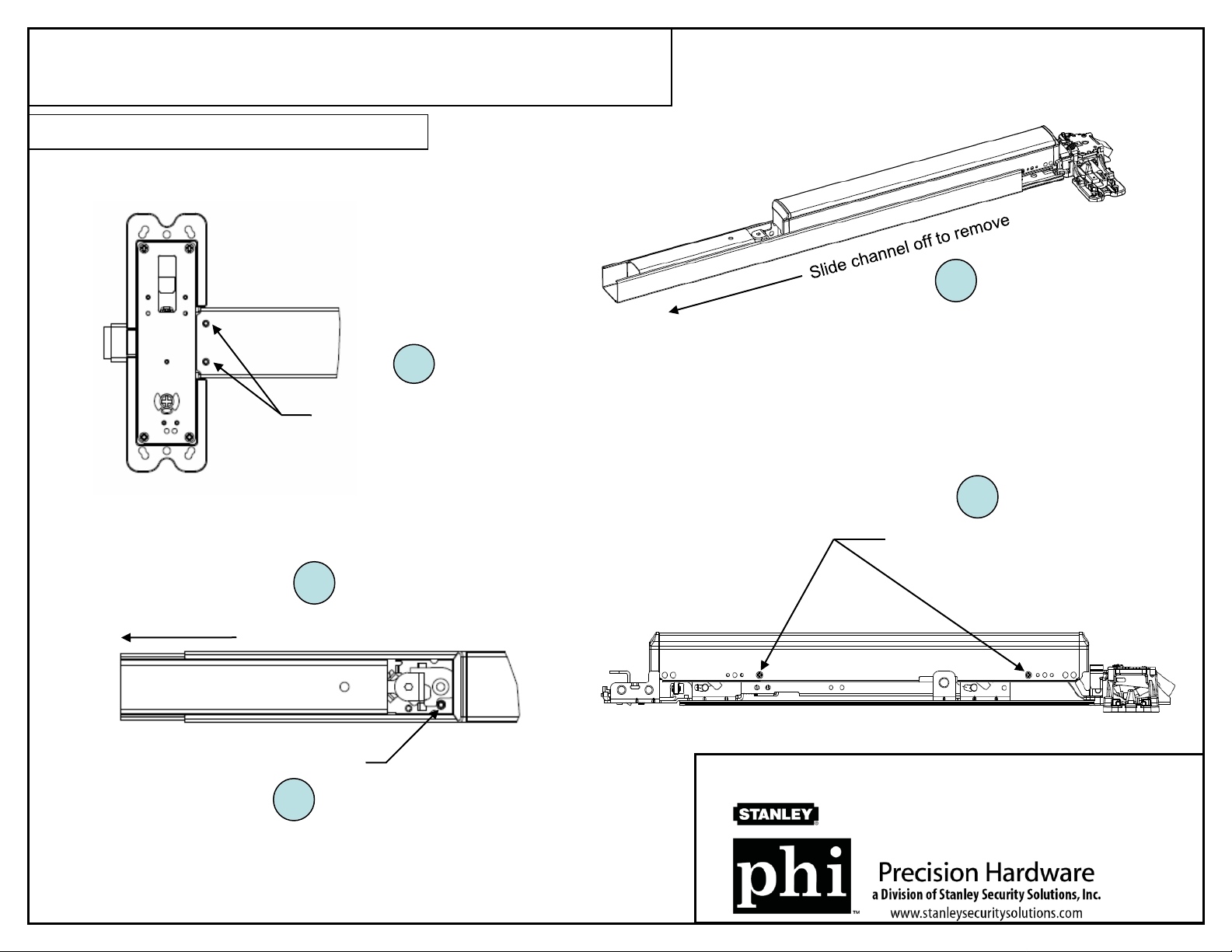
(1) Disassemble Channel and Touchbar
1.1
Remove 2 screws on the bottom
side of the chassis/channel
(#8-32MS)
1.4
1.5
1.2
Slide filler out to allow access
Loosen set screw
1.3
Note: Hex-dogging rim assembly is shown as example only.
Remove 4 touchbar screws
(#8-32MS, 2 screws per side)
Q Option Upgrade Kit Installation Instructions
QSRK5267 / QSVK5268 Conversion Kits Page 1 of 3
REV DATE DRWG
B 12/4/2008 05269-11-000
Page 2
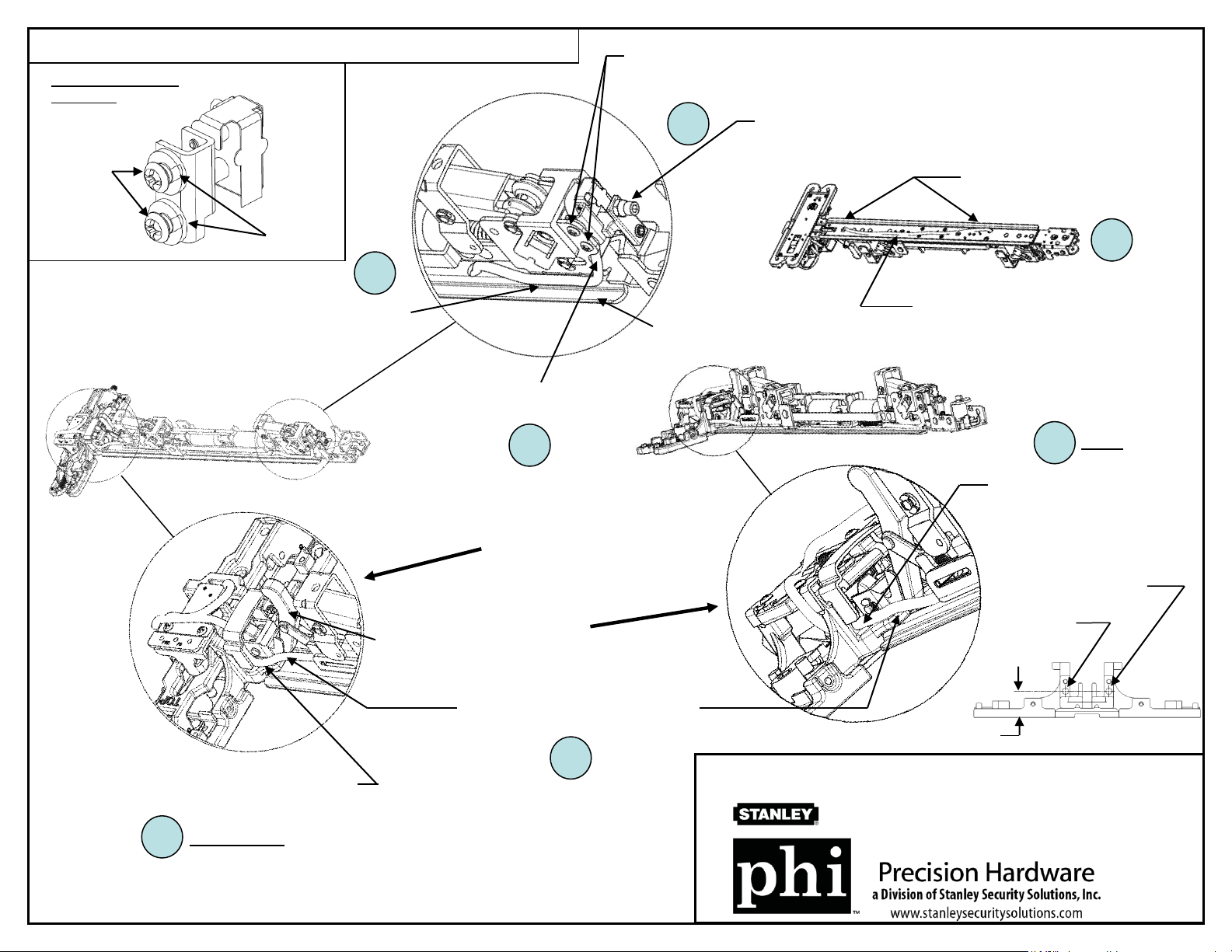
(2) Install Touchbar Switch Assembly and Route Wires
Q Touchbar Switch
Assembly
(wires not shown)
2 Screws
(#8-32MS)
Plastic
Washers
2.3
Mount Q Touchbar Switch with 2 screws (#8-32MS)
provided. Use plastic washers as spacers in-between the
assembly and bracket.
2.1
Mount and adjust Bolt & Nut appropriately
for switch activation.
Route harness through 2 holes at
either end of subplate as shown
and pull it snug.
2.4
Route harness as shown, keeping it
clear of lower lip to avoid pinching.
Lever Arm
Lower Lip
Route harness through
switch bracket.
2.2
VERTICAL
(2203, 2703, 2803)
or
RIM
(2103)
Dress harness clear of lever arm
and lower lip to avoid pinching.
Position harness in center and tape
down underneath subplate.
(RIM)
2.6
*Route harness through wire
hole in chassis. Keep clear
of moving parts.
( * - If no hole in chassis available,
disassemble and drill a thru hole)
#7 Drill (ǿ.201”)
for LHRB device
#7 Drill (ǿ.201”)
for RHRB device
.925”
Route harness up through lock side filler as
shown. Keep clear of moving parts and
cover.
(VERTICAL)
2.6
Note: ELR assembly is shown as example only.
2.5
Q Option Upgrade Kit Installation Instructions
QSRK5267 / QSVK5268 Conversion Kits Page 2 of 3
REV DATE DRWG
B 12/4/2008 05269-11-000
Page 3

For RIM applications (2103)
(3) Install Latchbolt Switch Assembly
Q RIM Latchbolt Switch Assembly
(wires not shown)
3.1
* Mount Q Rim Latchbolt Switch
Assembly to chassis with 2 screws
(#8-32MS) provided.
3.2
For Vertical applications (2203, 2703, 2803)
(3) Install Latchbolt Switch Assembly
Q Vertical Latchbolt Switch
Assembly
(wires not shown)
3.1
** Mount Q Vertical Latchbolt Switch
Assembly to chassis with 2 screws
(#8-32MS) provided. Keep existing
cam bracket assembly held in place
while adding this assembly.
Dress harnesses as
shown, keeping them
clear of moving parts.
Secure harnesses with
cable clamp or tape to
top of chassis.
LHRB handing is shown.
Mount switch on opposite
side for RHRB.
* Note: Switch leaf should be positioned under
backside of latchbolt when mounted.
Note: ELR assembly is shown as example only.
(4) Reassemble device by reversing steps 1.1 to 1.5
Note: Refer to EXQ trim installation instructions for
wire connections.
RHRB handing is shown.
Mount switch on opposite
side for LHRB.
Q Option Upgrade Kit Installation Instructions
QSRK5267 / QSVK5268 Conversion Kits Page 3 of 3
3.2
Dress harnesses as
shown, keeping them
clear of moving parts.
Secure harnesses with
cable clamp or tape to
top of chassis.
** Note: Switch leaf should be positioned in
front of rod carriage features when mounted.
REV DATE DRWG
B 12/4/2008 05269-11-000
 Loading...