

Page 1
EL Series
QEL 200 Electronic Lock
User Guide
www.stanleysecuritysolutions.com/el
Page 2

Information in this document is subject to change without notice and does not represent a commitment on the part
of Stanley Security Solutions, Inc. The software described in this document are furnished under a license agreement or
nondisclosure agreement.
This publication is intended to be an accurate description and set of instructions pertaining to its subject matter.
However, as with any publication of this complexity, errors or omissions are possible. Please call Stanley Security
Solutions, Inc at (855) 365-2407 if you see any errors or have any questions. No part of this user guide may be
reproduced or transmitted in any form or by any means, electronic or mechanical, including photocopying, recording,
or information storage and retrieval systems, for any purpose, without the expressed written permission of Stanley
Security Solutions, Inc.
This document is distributed as is, without warranty of any kind, either expressed or implied, respecting the contents
of this book, including but not limited to implied warranties for the publication’s quality, performance, merchantability,
or tness for any particular purpose. Neither Stanley Security Solutions, Inc, nor its dealers or distributors shall be liable
to the user or any other person or entity with respect to any liability, loss, or damage caused or alleged to be caused
directly or indirectly by this publication.
QEL 200 is a registered trademark of Stanley Security, Inc.
Intelli-M is a registered trademark of Innias Inc.
Microsoft, Windows, and CE are registered trademarks of Microsoft Corporation.
FCC Certication
This equipment has been tested and found to comply with the limits for Class B Digital Device, pursuant to Part
15 of the FCC Rules. These limits are designed to provide reasonable protection against harmful interference in a
residential installation. This equipment generates and can radiate radio frequency energy and, if not installed and used
in accordance with the instructions, may cause harmful interference to radio communications. However, there is no
guarantee that interference will not occur in a particular installation. If this equipment does cause harmful interference
to radio or television reception, which can be determined by turning the equipment off and on, you can try to correct
the interference by taking one or more of the following measures:
Reorient or relocate the receiving antenna
Increase the separation between the equipment and receiver
Connect the equipment into an outlet on a circuit different from that to which the receiver is connected
Consult the dealer or an experienced radio/TV technician for help.
This device complies with Industry Canada license-exempt RSS standard(s). Operation is subject to the following two
conditions: (1) this device may not cause interference, and (2) this device must accept any interference, including
interference that may cause undesired operation of the device.
Under Industry Canada regulations, this radio transmitter may only operate using an antenna of a type and maximum
(or lesser) gain approved for the transmitter by Industry Canada. To reduce potential radio interference to other users,
the antenna type and its gain should be so chosen that the equivalent isotropically radiated power (e.i.r.p.) is not more
than that necessary for successful communication.
This radio transmitter (identify the device by certication number, or model number if Category II) has been approved
by Industry Canada to operate with the antenna types listed below with the maximum permissible gain and required
antenna impedance for each antenna type indicated. Antenna types not included in this list, having a gain greater than
the maximum gain indicated for that type, are strictly prohibited for use with this device. Approved antennas are listed
below.
Approved Antennas
Rubber Duck Antenna (L-Com HG2402RD-RSF, 2.2dBi Gain , 50 Ohms )
Remote Mount Antenna (Maxrad Model MC2400PT, 2.5dBi Gain, 50 Ohms)
Rubber Duck Antenna (Antenna Factor ANT-2.4-CW-RCT-xx, 2.2dBi Gain , 50 Ohms )
This product produces radio frequency energy and was evaluated to and meets the general population / uncontrolled
RF exposure limits at a separation distance of 20cm. Installation of this device must be such that the 20cm is ensured.
IMPORTANT! Any changes or modications not expressly approved by the party responsible for compliance could void
the user’s authority to operate the equipment.
A86094 REV A Copyright© 2013 Stanley Security Solutions, Inc.
Page 3

EL Series3
Contents
4 Glossary
5 Overview
7 Stand-Alone System
8 Setup Steps
8 Needed Tools
8 Install Stand-Alone Locksets
9 Stand-Alone Management
17 Wireless System
18 Setup Steps
18 Needed Tools
19 Conduct Site Survey
22 Access Control Software
23 Congure and Install Gateway
36 Install Wireless Locksets
37 Install QIC
39 Replace, Upgrade, & Update
40 Replace
45 Upgrade
45 Update
47 Troubleshoot
Page 4

4EL Series
Glossary
access control software (ACS) wireless access control management system
ACS Server server where the Intelli-M ACS is already installed
construction key temporary key used during construction
ethernet networking standard
factory reset reseting the lockset or gateway to factory settings
gateway device which securely transfers data signals from
wireless reader locks to/from the Host computer
IP address numeric address (like 192.168.1.1) that identies each
device in a TCP/IP network
MAC address a unique 12-digit number assigned by a device
manufacturer
master programming card card that allows the enrollment or removal of users
normal mode normal operating mode that allows access to users
that have been added to the lockset
operator card card assigned to a user with access credential
operator key key used to unlock and lock lockset
passage mode lockset stays unlocked, allowing access without need
to present operator card.
QIC powerful single door PoE Controller
segment code access information encoded to a card, usually
numerical, and unique to a group of credentials
shadow card copy of operator card to be used to remove a user
from the lockset
site survey kit determines optimum Gateway location to verify
signal strength before installation
stand-alone lockset lockset not connected to an access control system;
accessibility local at door
stand-alone management managing user access for the stand-alone lockset
temporary operator card card used to gain access to factory reset/default
lockset
timezone dened range of time for various access control
activities
user individual with a particular access credential
wireless lockset lockset which controls access at the door and grants
user requests according to how they’re congured in
the ACS
Page 5
EL Series5
Overview
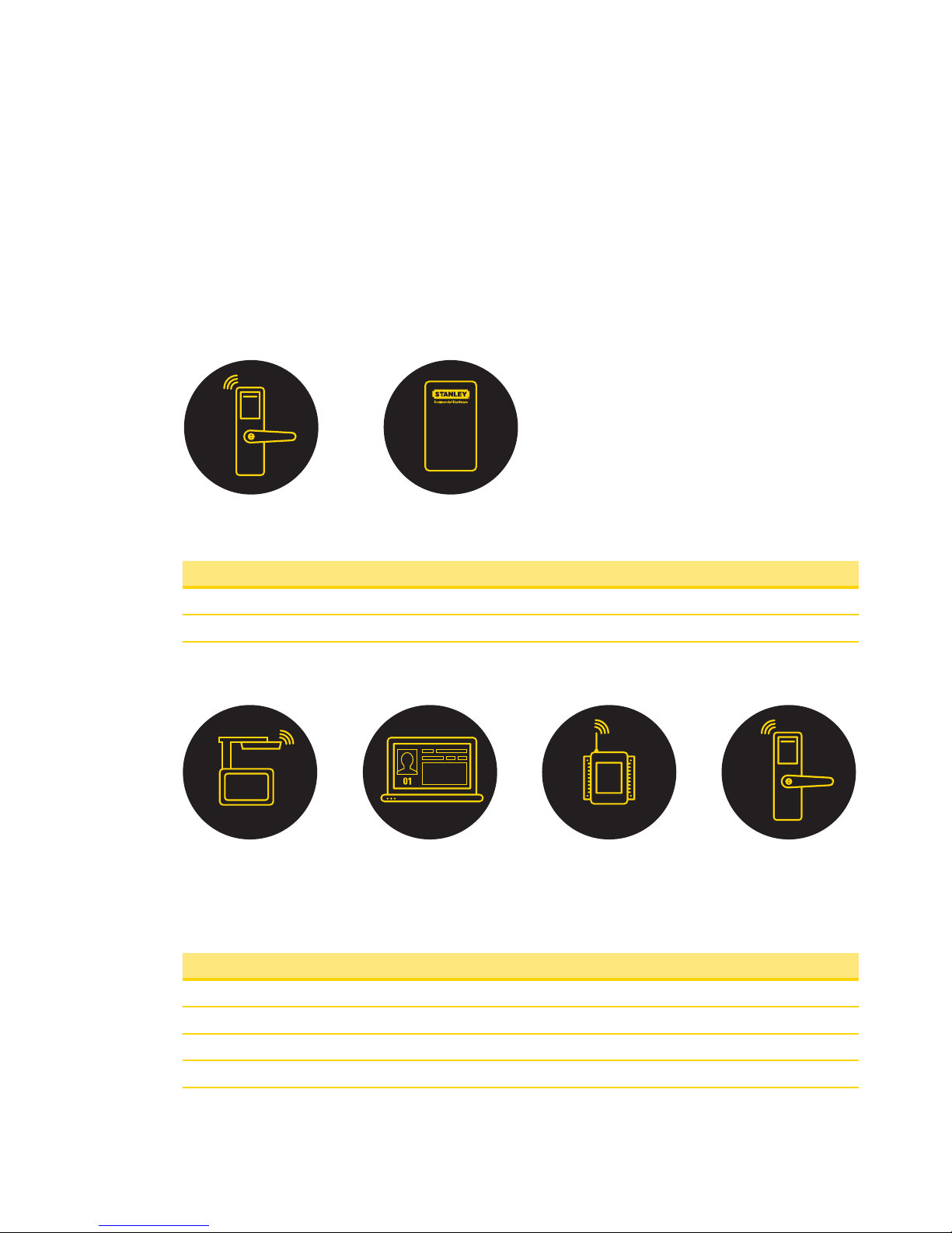
The QEL 200 lockset can function as two separate systems. The Stand-Alone system
allows for Stand-Alone Management at the door. The Wireless system combines
powerful access control software with Gateways and Wireless Locksets to control user
access.
Components
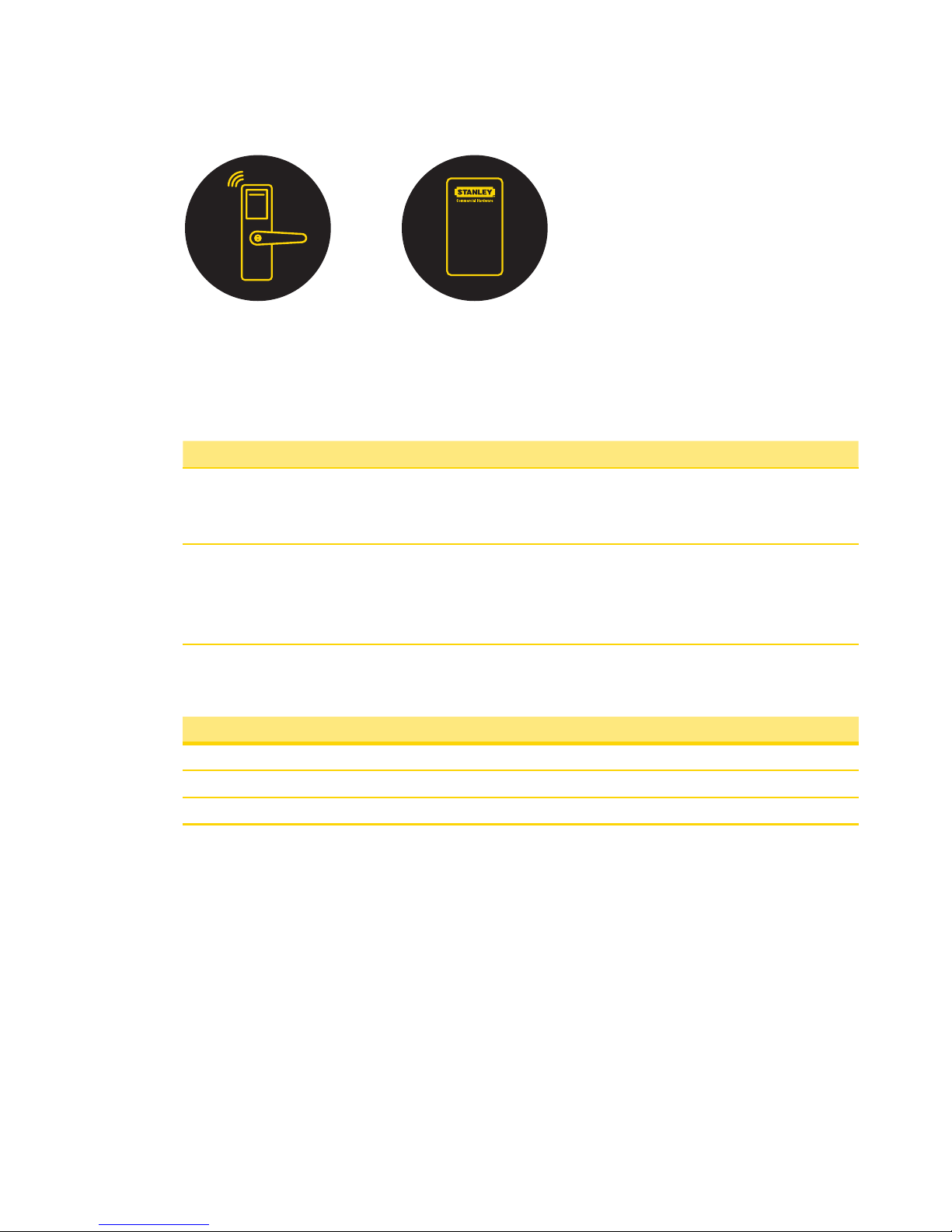
A Stand-Alone system has 2 components:
Components
1 QEL 200 Lockset
2 Stand-Alone Management
A Wireless system has 4 components:
Components
1 QES Site Survey Kit
2 Access Control Software (Wireless Management)
3 QEW Gateway
4 QEL 200 Lockset
21
1 2 3 4
Page 6

Page 7

Stand-Alone System
1
Page 8
8Stand-Alone System
Setup Steps
Needed Tools
Steps Tool s
1 Install Stand-Alone Lockset • Lockset Installation Instructions and
Template
• Core/Key Pack or Construction Core Pack
2 Stand-Alone Management • Core/Key Pack or Construction Core Pack
• Temporary Operator Card
• Operator Card(s)
• Shadow Card(s)
Install Stand-Alone Locksets
Steps
1 Check Installation Settings
2 Prepare Doors
3 Install Locksets
Check Installation Settings
QEL 200 Locksets are for use inside protected areas. Changes or modications not
expressly approved by Stanley Security Solutions could void the user’s authority to
operate the equipment.
Note Locksets work within a temperature range of -31°F to 151°F. Exposure to
extreme temperatures may void the warranty.
21
Page 9
Stand-Alone System9
Prepare Doors
Use the template provided with the lockset package to prepare the installation. You can
also nd the template at www.stanleysecuritysolutions.com/el.
Install Locksets
Use the installation instructions provided with the lockset package. You can also nd
installation instructions at www.stanleysecuritysolutions.com/el.
Stand-Alone Management
Steps
1 Test Functionality
2 Temporary Operation
3 Enrolling Master Programming Card
4 Enrolling Users
5 Removing Users
6 Normal Mode
7 Passage Mode
8 Replacing Batteries
9 Factory Reset
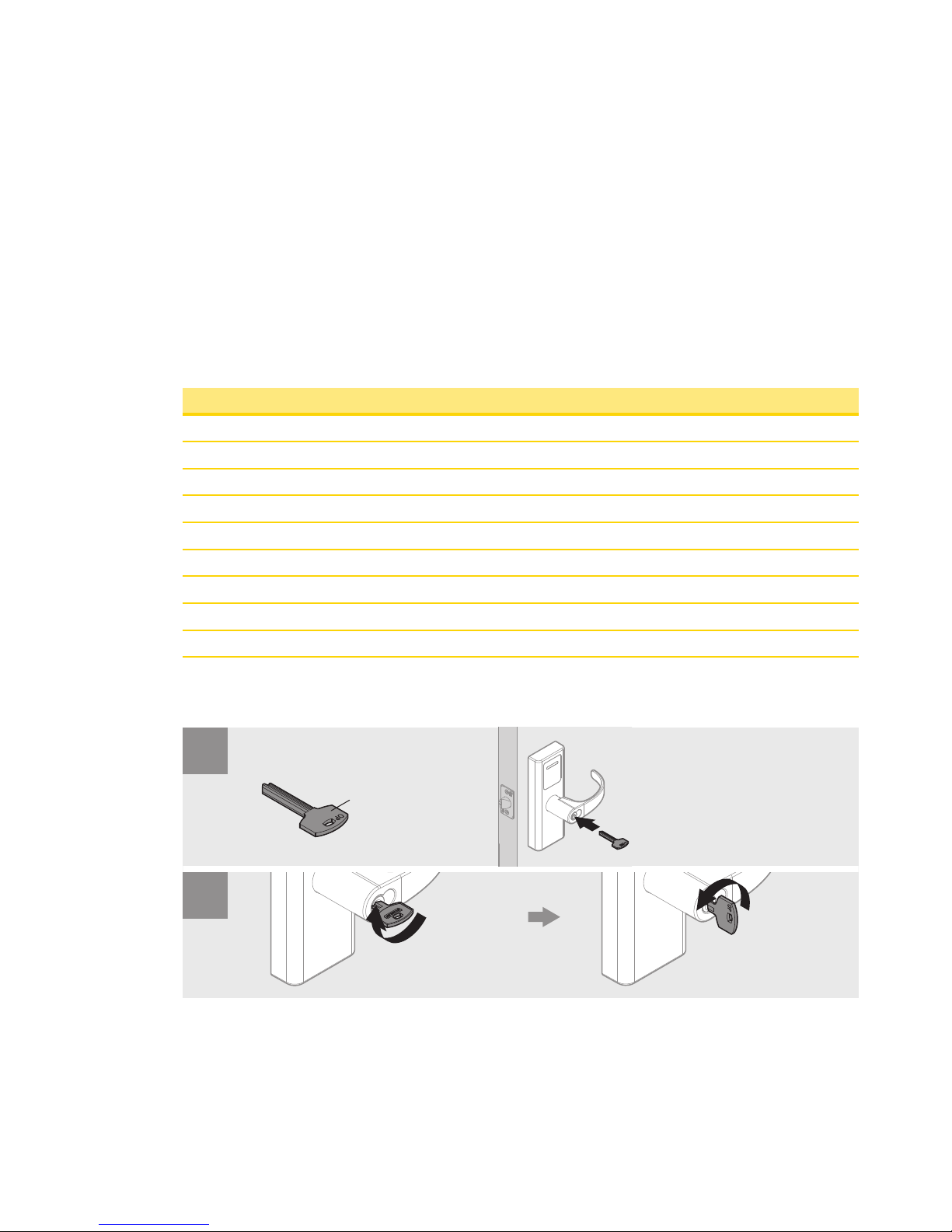
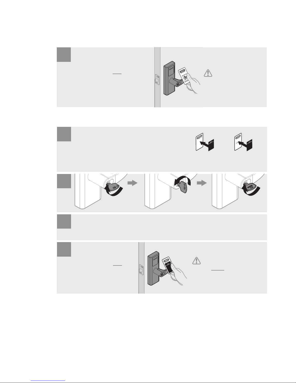
Test Functionality
Operator Key
1
2
Unlock
Lock
Rotate Fully
Rotate Fully
Page 10
10Stand-Alone System
Temporary Operation
Enrolling Master Programming Card
Present Temporary Operator Card ONCE. The lockset
will unlock, accompanied by a green light. Lockset will
relock after 5 seconds.
1
Once the rst Operator Card
is enrolled, the Temporary
Operator Card is void.
((1x))
Rotate Fully Rotate Fully
Rotate Fully
Choose 1 Proximity Card Pack as the Master Programming Card pair. Place Label
(Z3) on both. Store Shadow Card away safely for future use.
The rst card that you add
becomes the Master Programming
Card. DO NOT assign the Master
Programming card to a user.
1
After QEL 200 ashes orange and gives an audio cue, remove key.
2
Present Master Programming Card ONCE and a
green light will conrm that the card has been
accepted.
((1x))
4
3
Page 11
Stand-Alone System11
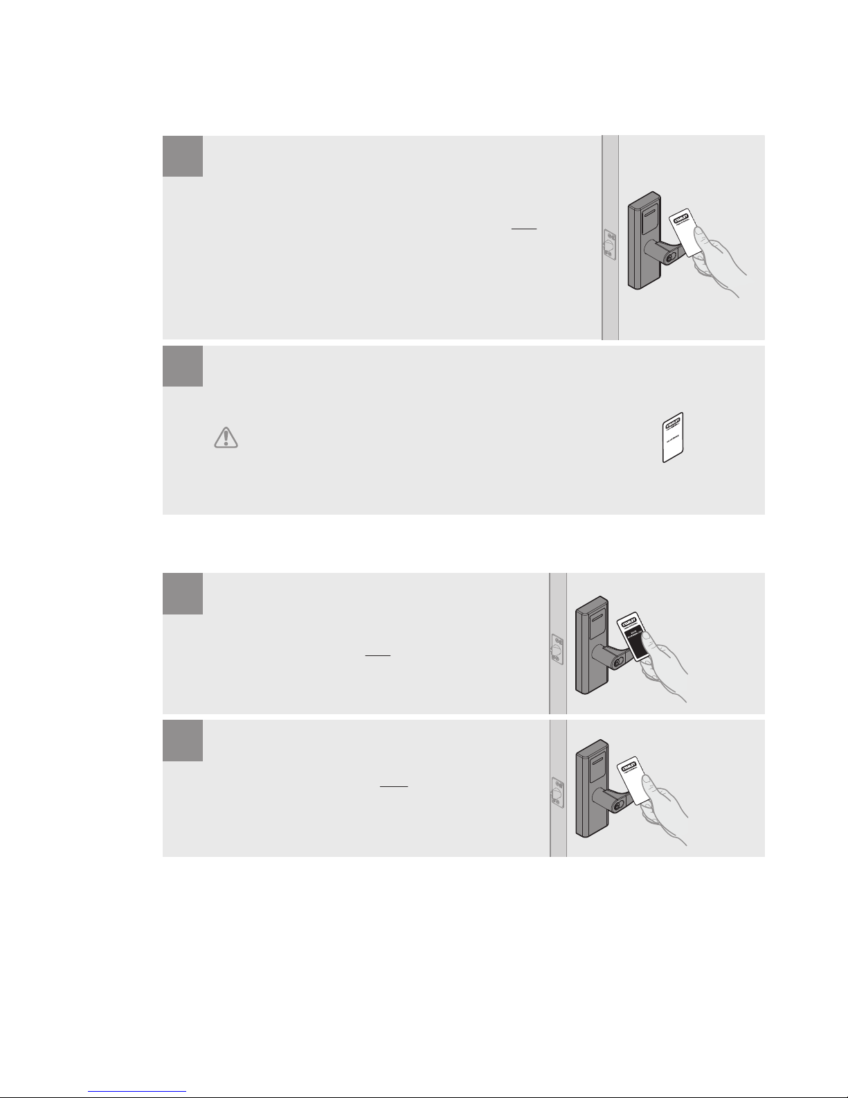
Enrolling Users
Removing Users
Present Master Programming Card rst. Immeditely present new Operator Card ONCE and a
green light will conrm that the user has been added. Continue to add the rest of your Users. If
there is no proximity card interaction for 10 seconds, the mode will time out and return to
Normal Mode.
((1x))
1
The Shadow Card from the pack of the newly added Operator Card is needed if the Operator Card is
lost or destroyed. The administrator may use the Shadow Card to remove the lost or destroyed
Operator Card from QEL 200’s database. It must be stored away safely for future use.
2
If both the Operator Card and the Shadow Card are lost, you will have to reset the lock.
Present Master Programming Card ONCE.
Z1
((2x))
1
((1x))
Immedietly present Operator Card (Z1) TWICE in rapid succession
and a red light will conrm that the user has been removed.
2
Page 12

12Stand-Alone System
Normal Mode
Passage Mode
Present Operator Card ONCE. If the user has been added, the
lockset will enter Normal Mode, accompanied by a green light.
((1x))
1
To EXIT Passage Mode, present
Operator Card TWICE in rapid
succession. A green light will
conrm the end of Passage Mode.
((2x))
Present Operator Card TWICE in rapid succession. If
the user has been added, the lockset will stay
unlocked, accompanied by a green light.
1
Page 13
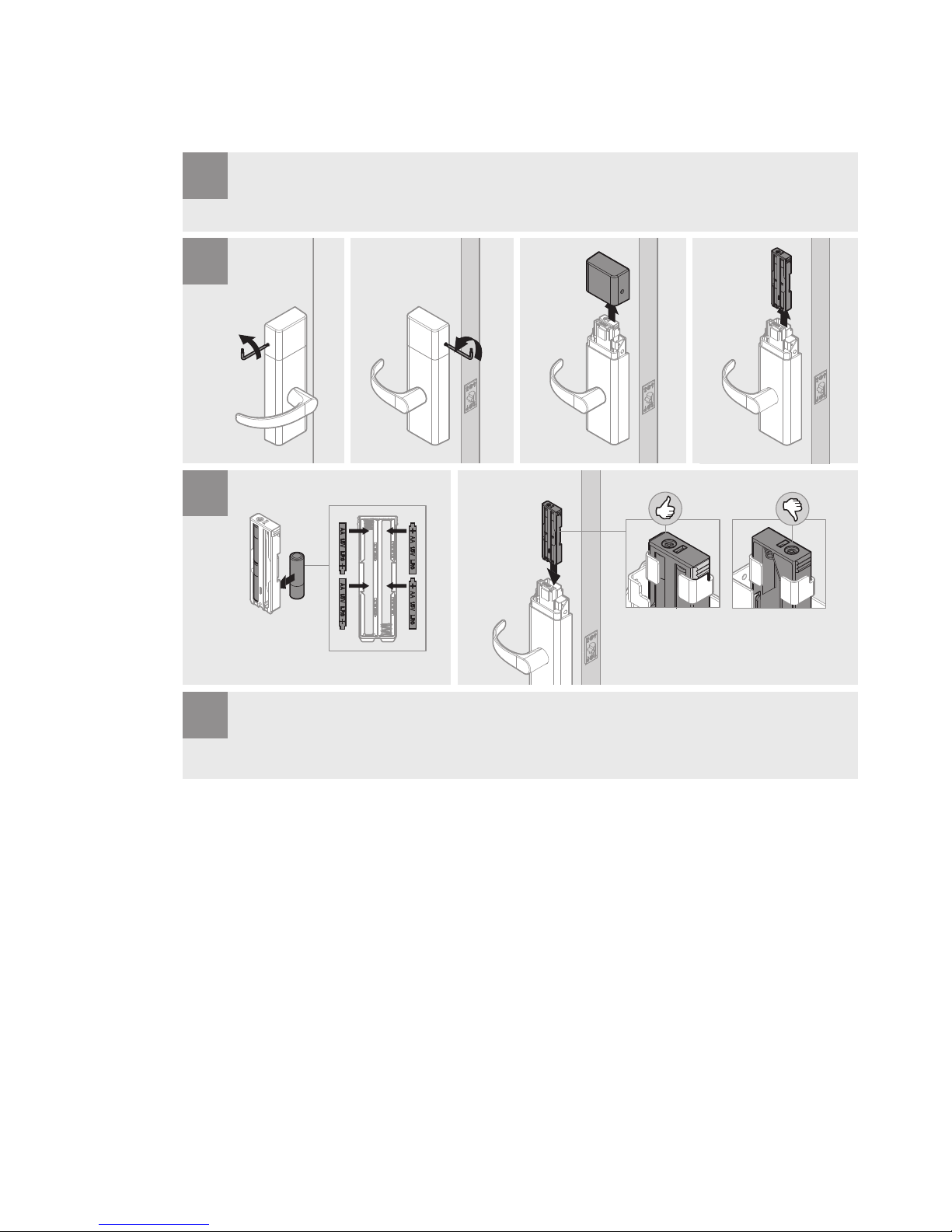
Stand-Alone System13
Replacing Batteries
Low battery will ash a warning orange light every minute until the batteries are replaced.
1
An audio cue will conrm battery connection. Reinstall Battery Cover.
2
3
4
Page 14
14Stand-Alone System
Factory Reset
1
Press and hold the S1 button while inserting
the battery (wait at least 5 seconds of
holding the S1 button before inserting the
battery). Continue to hold the S1 button
until an audio cue conrms reset, then
release. Temporary Operator Card should
now work. Reinstall Interior Escutcheon,
Battery Cover, and Non-Keyed Lever.
2
3
Page 15

Stand-Alone System15
Your Stand-Alone Lockset is now ready for regular use. If you experience any issues,
please visit Chapter 4, Troubleshoot or contact the Stanley Technical Support Team at
(800) 392-5209.
Page 16

Page 17

17
Wireless System
2
Page 18

18Wireless System
Setup Steps
Needed Tools
Steps Tool s
1 Conduct QES Site Survey • Site Survey Kit
• Site Survey Kit Quick Start Guide
2 Download Software or Install ACS
Server
• If you are downloading the software,
you will need a Host Computer (where
you installed the ACS) and the ACS
User Guide
• If you are Installing the ACS Server, see
the ACS Quick Start Guide that came
with the package
3 Congure and Install Gateway • Gateway Installation Instructions and
Template
• PC Computer with Windows 7 or above
• Host Computer’s IP Address, Subnet
Mask, and Gateway Number)
4 Install Wireless Locksets or QIC • If you are installing Wireless Locksets,
you’ll need: Lockset Installation
Instructions, Template, and Quick Start
Guide, Core/Keyset or Construction
Core Pack, Wireless Board, Temporary
Operator Card, Operator Cards
• If you are installing the QIC, you’ll
need: QIC Qick Start Guide
1 2 3 4
Page 19

Wireless System19
Conduct Site Survey
Steps
1 Gateway placement
2 Document gateway and lockset identication
3 Position gateways
Gateway Placement
Prior to the Gateway installation, a technician must perform a QES Site Survey. You can
nd the QES Site Survey Quick Start Guide at www.stanleysecuritysolutions.com/el.
The technician may need you to make a site plan with building dimensions, distances
between buildings, possible obstruction, parking, and other gated access points prior
to the site survey. If one is not available through your facilities maintenance or project
engineer, visit the site to take measurements to create one.
250 ft
150 ft
Patient Room
Surgery Room Patient Room Lobby
ClosetDentist Ofce
Page 20

20Wireless System
The most common installation site is in a protected area such as a locked room or above
ceiling level. Use the template provided with the QEW Gateway package to prepare for
installation. You can also nd the template at www.stanleysecuritysolutions.com/el.
Gateway Range
The Gateway is a wireless device connected to the Host computer through a secure IP
address, similar to the way your computer is connected to the internet. It transfers data
signals from Wireless Locksets to and from the Access Control Software. One Gateway
can control up to 64 Wireless Locksets.
Gateways provide bidirectional radio frequency communication between Wireless Locksets
and the associated Host Computer. All communications are via secure AES 128-Bit encrypted
2.4 GHz using spread spectrum RF Radio technology. The Gateway communicates to the
Host Computer through web services via either Ethernet 10/100 BaseT, or an approved
commercial RF carrier-enabling a wireless solution end-to-end.
Transmit range from Gateway to lockset varies based on building construction and wi
noise. Site characteristics such as reinforced concrete walls could interfere or weaken
the signal; open spaces and low interference can increase signal strength.
Stanley transfers information between devices in the form of data packets over the 2.4
GHz ISM band. This band frequency is very heavily used in many devices such as wireless
computer networks (802.11 b and g) and cordless phones, which increases the risk of
lost packets, that is, packets that do not make it from a lockset to a Gateway because
of interference. Interference can also reduce lockset battery life due to the constant rebroadcasting of packets and lost connections to the gateways. However, the gateway is
a proprietary wireless stack and not the same as a wi router.
Page 21

Wireless System21
To achieve maximum efciency in wireless system, the frequency range must be
managed effectively. Therefore, the installer must know the positions and channels of
all the 2.4 GHz wireless devices in the segment and ensure channels are assigned to each
device so that there is minimum frequency overlap with adjacent or nearby devices.
Note Always use the site survey kit to optimize gateway placement and calculate the
number of gateways needed for optimal signal strength.
Gateway Power Supply
Gateways must be located near lockset and either two options:
AC/DC AdaptorPower Over Ethernet
or
Must have access to a 120VAC wall outlet no more
than 6 ft. away.
Must have access to Ethernet 10/100 Base T
network connection.
Network Cable
(For P.O.E.)
*Ordered
Separately
Network
Cable
AC/DC
Input: 100-240V
50Hz/60Hz 25W
Output: 24V DC 1A
Page 22

22Wireless System
Access Control Software
Steps
1 Download Software/Install ACS Server
2 Collect User Information
3 Congure Access Control Software
Download Software/Install ACS Server
Visit www.stanleysecuritysolutions.com/el to download your Access Control Software.
If you have the ACS Server, please follow the Quick Start Guide that came with your
package.
Collect User Information
You will need to gather the names of users, dene their access requirements, organize
user and time zone groups, and decide how to use other congurable features.
Create a table with information about each user, such as: User Type, User Group, Shift,
etc.
Last First User Type Bldg. User
Group
Time zone
Alverez Alicia Dentist A Admin Default
Bennet Ryan Sr. Technician A Basic Default
Ford Sara Technician A Basic Default
Lee James Receptionist A Basic Default
To organize your data, consider the following issues:
• What User Groups will help manage security?
• Are some shift workers allowed on site only during specic days/hours?
• Are some areas ‘off limits’ to certain groups?
• Do some users need extra time to pass through a door (e.g. because of a food cart or
wheel chair)?
Page 23

Wireless System23
Congure Access Control Software
Please see your Access Control Software User Guide at
www.stanleysecuritysolutions.com/el to congure for the EL Series.
Note You must congure and install the gateway before conguring the Access
Control Software.
Congure and Install Gateway
Steps
1 Connect Gateway
2 Congure Gateway to Network
3 Install Gateway
4 Verify Operation
Connect Gateway
PC User
1 Connect Gateway to PC.
2 Go to Start > Computer > Network
Network Cable
AC/DC Adaptor
A
B
Page 24

24Wireless System
3 Double Click on Stanley QEW Gateway Icon.
Note You may have to wait a 3-5 minutes until the Gateway icon appears. If Gateway
does not appear, see Chapter 4, Troubleshoot.
4 Continue on to Congure Gateway to Network.
Page 25

Wireless System25
Congure Gateway to Network
The Gateway Conguration site creates communication between the locksets and
Access Control Software. Please follow the steps below for setup.
1 Enter Default Password: password
2 Click LOGIN.
3 Stanley recommends changing your administrator password to increase security.
Page 26

26Wireless System
4 Click Next.
5 Choose DHCP or Manual Conguration.
Note Stanley recommends selecting Manual Conguration and the following
instructions will only go over Manual Conguration. If you choose DHCP and
have any issues, please contact Stanley Technical Support at (855) 362-2407.
Page 27

Wireless System27
6 Enter the IP Address that you want this device to have, your computer’s Subnet
Mask, and Gateway.
Page 28

28Wireless System
7 Choose your Time Zone.
8 Click Next.
Page 29

Wireless System29
9 Conrm your Network Congurations by Clicking Save.
Page 30

30Wireless System
10 Follow the instructions indicated in the black square. It may take 3-5 minutes for the
icon to be discovered.
11 Once you have reached the following page, close the window.
Page 31

Wireless System31
12 Disconnect the gateway from the laptop.
13 Connect the Gateway where you intend to install it. It must now be connected to
your network to move forward.
14 Go back to your Gateway Conguration site by Double Clicking on Gateway icon or
typing the assigned IP Address into your browser.
Network Cable
AC/DC Adaptor
A
B
Page 32

32Wireless System
15 Login to the Gateway Conguration Site.
Page 33

Wireless System33
16 Enter the IP Address of your Host Computer. This is where you installed the Access
Control Software.
17 Click Finalize and receive the following screen:
Page 34

34Wireless System
18 Gateway Conguration is complete. Log out and close window.
Page 35

Wireless System35
Install Gateway
Use the installation instructions provided with the QEW Gateway package. You can also
nd installation instructions at www.stanleysecuritysolutions.com/el.
Verify Operation
Once installation has completed, verify that the gateway is operating.
• Power light must be lit to verify operation.
• The Ethernet Activity light blinking veries the connection to the network.
• Wireless Communication light blinking veries the communication between the
wireless locksets and the gateway (this will take place once the locksets have been
installed).
Wireless CommunicationPower
Reset Button
Ethernet Activity
Page 36

36Wireless System
Install Wireless Locksets
Steps
1 Check Installation Settings
2 Document Lockset Identication
3 Prepare Doors
4 Install Wireless Locksets
Check Installation Settings
Locksets are for use inside protected areas. For other applications (such as outdoor use),
contact the factory for the appropriate NEMA enclosure. Changes or modications
not expressly approved by Stanley Security Solutions could void the user’s authority to
operate the equipment. Make sure to check temperature. Stanley locks will work from
-31°F to 151°F.
Note Locksets work within a temperature range of -31°F to 151°F. Extreme heat
reduces wireless signal strength and may cause a loss of connectivity.
Document Lockset Identication
The MAC Address will be needed to locate the lockset in the Gateway and ACS.
Prepare Doors
Use the template provided with the lockset package to prepare the installation. You can
also nd the template at www.stanleysecuritysolutions.com/el.
Record MAC Address (i.e. BDA9) and location of lockset.
W
Model: ZICM357SPO-1
FCC ID: W7Z-ZICM357SPO
IC: 8254A-ZICM357SPO
M:000BDA9
Lot: 121BG
1
Page 37

Wireless System37
Install Wireless Locksets
Use the installation instructions provided with the lockset hardware. You can also nd
installation instructions at www.stanleysecuritysolutions.com/el.
Install QIC
If you have purchased the Stanley QIC, which is a powerful single door PoE Controller,
please follow the quick start guide that came with your package.
Page 38

Page 39

Replace, Upgrade, & Update
3
Page 40

40Replace, Update, & Upgrade
Replace
The following items are the only available parts to replace for the EL Series. Please
contact your Stanley distributor to order or visit www.stanleysecuritysoulutions.com/el.
Site Survey Kit Replaceable Parts
A
73203415 Emulator
B
73203529 6-32 Phillips Screws
C
73203360 Battery Cover
D
73203529 4 AA Batteries
E
73203366 Scepter Battery (not pictured)
F
73203363 Scepter Charger
G
73203338 Battery Case
B
(4x)
D
(4x)
A
G
F
C
Page 41

Replace, Update, & Upgrade41
Gateway Replaceable Parts
A
73203415 Rubber Duck Antenna
B
73203364 Gateway
C
73203529 Ceiling Mount Antenna Kit
D
73203365 AC/DC Adaptor
20 ft Plenum Rated
A
C
B
D
20 ft Plenum Rated
Page 42

42Replace, Update, & Upgrade
Lockset Replaceable Parts
Finish Name PN
A
605 Keyed Lever 73203340
A
626 Keyed Lever 73203341
A
690 Keyed Lever 73203342
B
605 Exterior Lock Assembly 73203385
B
626 Exterior Lock Assembly 73203386
B
690 Exterior Lock Assembly 73203387
C
605 Square Corner Latch 73203343
C
626 Square Corner Latch 73203344
C
690 Square Corner Latch 73203345
E
D
K
P
G
H
(4x)
F
C
Q
R
B
M
A
J
L
W
Wireless Locks Only
N
O
Page 43

Replace, Update, & Upgrade43
605 Round Corner Latch (not pictured) 73203346
626 Round Corner Latch (not pictured) 73203347
690 Round Corner Latch (not pictured) 73203348
D
605 STK Strike 73203352
D
626 STK Strike 73203353
D
690 STK Strike 73203354
605 Extended STK Strike (not pictured) 73203572
626 Extended STK Strike (not pictured) 73203573
690 Extended STK Strike (not pictured) 73203574
E
605 ANSI Strike 73203349
E
626 ANSI Strike 73203350
E
690 ANSI Strike 73203351
605 Extended Lip ANSI Strike (not pictured) 73203569
626 Extended Lip ANSI Strike (not pictured) 73203570
690 Extended Lip ANSI Strike (not pictured) 73203571
F
Interior Lock Assembly 73203383
G
Battery Case 73203338
H
4 AA Batteries 73203366
J
605 Interior Escutcheon 73198547
J
626 Interior Escutcheon 73198548
J
690 Interior Escutcheon 73198549
K
Battery Cover w/ Label 73203707
L
605 Non-Keyed Lever 73198553
L
626 Non-Keyed Lever 73198554
L
690 Non-Keyed Lever 73198555
M
Temporary Operator Card 73203453
N
1 3/8 Thin Door Shim Kit 73203711
O
605 Screw Pack 73198635
O
626 Screw Pack 73198636
O
690 Screw Pack 73198637
Page 44

44Replace, Update, & Upgrade
P
Construction Core Pack 73203355
Q
Keys and Cores
Ordered
through
System
R
Operator and Shadow Card Pair 73203454
W
Wireless Upgrade Kit 73203544
Exterior Escutcheon Gasket (not pictured) 73203575
QIC Replaceable Parts
Finish Name PN
A
QIC 7212678
A
Page 45

Replace, Update, & Upgrade45
ACS Replaceable Parts
Finish Name PN
A
ACS 7212679
B
ACS-ADC 7212680
A
B
Page 46

46Replace, Update, & Upgrade
Upgrade
Stand-Alone System to Wireless System
To upgrade your EL Series from a Stand-Alone system to a Wireless System, please visit
www.stanleysecuritysolutions.com/el or contact your Stanley distributor.
Update
To update your Gateway’s software or to update the Lockset rmware, you must revisit
the Gateway Conguration Site:
1 If you are a PC User, Go to Start > Network and double click on the Stanley QEW
Gateway icon or enter the Gateway’s default IP Address (169.254.10.1) into your
chosen browser.
2 Click on UPDATE.
3 You may either update the Gateway or Lockset.
Note Continue to check online for the most up-to-date instructions, templates, and
guides at www.stanley-securitysolutions.com/el.
Page 47

Page 48

Page 49

Troubleshoot
4
Page 50

50Troubleshoot
Occasionally, you may have problems when working with the EL Series. Read on for
troubleshooting tips. If you need further help, please call Stanley Technical Support at
(800) 392-5209.
Note For Access Control Software troubleshooting, please see your ACS User Guide.
Page 51

Troubleshoot51
Emulator LEDs do
not light up.
Battery Case has
not been dropped
properly into the
Emulator.
Problem Cause Solution
Batteries have
expired.
QES Site Survey
Pull back Retainer Tab
while pushing down on
Battery Holder.
New Batteries
2
3
1
Page 52

52Troubleshoot
Sceptor recieves
red light from
Emulator or no
signal at all.
Problem Cause Solution
Emulator
Batteries have
expired.
Replace Emulator Batteries by following the instructions on the previos page.
Emulators are too
far for proper
signal.
Sceptor needs
charging.
QES Site Survey
If the Scepter (A) displays a red color signal stength, you may need to nd a higher
strength area or may need more than 1 QEW Gateway. A single QEW Gateway
handles up to 64 locksets.
Page 53

Troubleshoot53
Gateway icon
does not appear
in computer
network.
Gateway is not
properly
connected to
computer.
Does not have
the proper
requirements.
QEW Gateway Conguration requires Windows 7 or higher and works with Inernet
Explorer 9 or above, Safari, Chrome, and Firefox. Make sure that you know your Host
Computer’s IP Address, Subnet Mask, and Gateway prior to conguration. The Host
Computer is where you installed the Access Control Software.
Please contact Stanley’s Technical Support Team at (800) 392-5209 for instructions.
Problem Cause Solution
Cannot remember
the Conguration
Login password.
You will have to physically reset the gateway by pushing the Reset Button on the
bottom and then continue to re-congure the gateway to your network.
Using another
web-based device
other than a PC.
QEW Gateway
Network Cable
AC/DC Adaptor
Reset Button
Page 54

54Troubleshoot
Problem Cause Solution
Interior or exterior
assembly does
not seat ush
aganist door.
Interior Assembly
did not correctly
align with Exterior
Assembly.
Spindle is in the
incorrect
position.
Bolts (R) must align and connect with exterior escucheon.
QEL 200 Lockset
Actual Size
Make sure Spindle is in the
Up-Right position.
Back View
Page 55

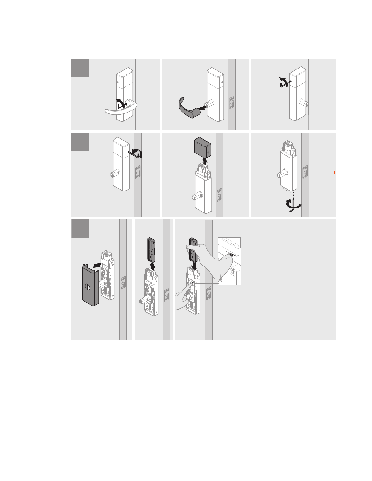
Troubleshoot55
Wireless Lockset
does not connect
to Gateway or
loses connection.
Wireless Card was
not correctly
inserted.
Wiring was not
properly
connected.
Batteries/Battery
Case was not
properly
connected.
(S1) button was
not properly
pressed.
Problem Cause Solution
Wireless locks only.
QEL 200 Lockset
Pins must align.
Connect wire harness.
Tuck wire harness.
Press (S1) TWICE in rapid succession to connect wireless
lockset to gateway.
Gateway must be installed prior to this step.
Page 56

 Loading...