

Page 1

Instruction Manual
QB Expert Alpha Controller
Software Version 5.2.8
English - Original Document - Revision C
© 2016 STANLEY Black and Decker, Inc. All rights reserved.
Page 2

Table of Contents
1 Getting Started . . . . . . . . . . . . . . . . . . . . . . . . 2
1.1 What’s Included . . . . . . . . . . . . . . . . . . . . . . . . . . 2
1.2 Controller Functions and Connections . . . . . . . . . . . . . . . 4
1.3 CE Directives (Europe) . . . . . . . . . . . . . . . . . . . . . . . 4
1.3.1 Machinery Directive Compliance . . . . . . . . . . . . . . . . . . .4
1.3.2 RoHS Compliance . . . . . . . . . . . . . . . . . . . . . . . . . . .5
1.3.3 WEEE Compliance . . . . . . . . . . . . . . . . . . . . . . . . . . .5
1.4 Regulatory Notices for Radio Transmitter . . . . . . . . . . . . . . . 5
1.4.1 FCC Notice (USA) . . . . . . . . . . . . . . . . . . . . . . . . . . .5
1.4.2 Canadian Compliance Notice . . . . . . . . . . . . . . . . . . . . . . .5
1.4.3 CE Notice (Europe) . . . . . . . . . . . . . . . . . . . . . . . . . . .6
1.5 Safety . . . . . . . . . . . . . . . . . . . . . . . . . . . . . . . . . 6
1.5.1 Warnings and Cautions . . . . . . . . . . . . . . . . . . . . . . . . . . .6
1.5.2 General Power Tool Safety Warnings . . . . . . . . . . . . . . . . . . .8
1.5.3 Safety Instructions for QB Expert Alpha Controllers . . . . . . . . . . 10
1.6 Specifications . . . . . . . . . . . . . . . . . . . . . . . . . . . . . . 11
1.6.1 Physical and Environmental Ratings . . . . . . . . . . . . . . . . . . 11
1.6.2 Electric Service Ratings . . . . . . . . . . . . . . . . . . . . . . . . . . 11
1.6.3 E-Stop Precaution . . . . . . . . . . . . . . . . . . . . . . . . . . 11
1.6.4 Tool Speed and Torque Scatter Versus Electric Supply . . . . . . . . . . 11
1.6.5 Tool Temperature Versus Electric Supply . . . . . . . . . . . . . . . . . . 11
1.7 Installation Instructions . . . . . . . . . . . . . . . . . . . . . . . 12
2 QPM QB Expert Alpha Controller . . . . . . . . . . . . 18
2.1 Data Storage . . . . . . . . . . . . . . . . . . . . . . . . . . . . . . 18
2.2 Input and Output Functions . . . . . . . . . . . . . . . . . . . 18
2.3 Software . . . . . . . . . . . . . . . . . . . . . . . . . . . . . . 18
2.4 Embedded PLC . . . . . . . . . . . . . . . . . . . . . . . . . . 18
2.5 Networking . . . . . . . . . . . . . . . . . . . . . . . . . . . . . . 18
2.6 Navigation . . . . . . . . . . . . . . . . . . . . . . . . . . . . . . 19
II
QB Expert Alpha Controller
Page 3

Table of Contents
2.7 Display . . . . . . . . . . . . . . . . . . . . . . . . . . . . . . 19
2.7.1 Scroll Bar . . . . . . . . . . . . . . . . . . . . . . . . . . . . . . . 19
2.7.2 Dropdown . . . . . . . . . . . . . . . . . . . . . . . . . . . . . . . 19
2.7.3 Menu Tree . . . . . . . . . . . . . . . . . . . . . . . . . . . . . . . 20
2.7.4 Tabs . . . . . . . . . . . . . . . . . . . . . . . . . . . . . . . . . . . 20
2.7.5 Character Scrollbar . . . . . . . . . . . . . . . . . . . . . . . . . . 20
2.7.6 Run Display . . . . . . . . . . . . . . . . . . . . . . . . . . . . . . . 20
2.7.7 Fastening Cycle Log . . . . . . . . . . . . . . . . . . . . . . . . . . 21
2.7.8 Keypad Mode . . . . . . . . . . . . . . . . . . . . . . . . . . . . . . . 24
2.7.9 Controller Display Icons . . . . . . . . . . . . . . . . . . . . . . . . . . 24
2.8 Faults . . . . . . . . . . . . . . . . . . . . . . . . . . . . . . . . . 25
2.9 Messages . . . . . . . . . . . . . . . . . . . . . . . . . . . . . . 26
3 Programming . . . . . . . . . . . . . . . . . . . . . . . 30
3.1 SETUP Area . . . . . . . . . . . . . . . . . . . . . . . . . . . . . . 30
3.1.1 JOBS: Wizard . . . . . . . . . . . . . . . . . . . . . . . . . . . . . . . 30
3.1.2 JOBS: Manual Programming . . . . . . . . . . . . . . . . . . . . . . 37
3.1.3 COMMUNICATIONS Menu . . . . . . . . . . . . . . . . . . . . . . 52
3.1.4 OTHER Menu . . . . . . . . . . . . . . . . . . . . . . . . . . . . . . . 66
3.1.5 RESTORE FACTORY DEFAULTS Menu . . . . . . . . . . . . . . . . . . 74
3.2 SERVICE Area . . . . . . . . . . . . . . . . . . . . . . . . . . 75
3.2.1 Tool . . . . . . . . . . . . . . . . . . . . . . . . . . . . . . . . . . . 75
3.2.2 Controller . . . . . . . . . . . . . . . . . . . . . . . . . . . . . . . 78
3.3 ANALYZE Area . . . . . . . . . . . . . . . . . . . . . . . . . . 79
3.3.1 TOOL Tab . . . . . . . . . . . . . . . . . . . . . . . . . . . . . . . 79
3.3.2 TRACE Tab . . . . . . . . . . . . . . . . . . . . . . . . . . . . . . . 81
3.3.3 STATS Tab . . . . . . . . . . . . . . . . . . . . . . . . . . . . . . . 82
3.3.4 LOG Tab . . . . . . . . . . . . . . . . . . . . . . . . . . . . . . . 83
3.3.5 I/O Tab . . . . . . . . . . . . . . . . . . . . . . . . . . . . . . . . . . . 84
4 Alpha Toolbox . . . . . . . . . . . . . . . . . . . . . . . 88
4.1 Connection . . . . . . . . . . . . . . . . . . . . . . . . . . . . . . . . . . . . . . 88
4.2 Controls . . . . . . . . . . . . . . . . . . . . . . . . . . . . . . . . . . . . . . . . . . 88
4.2.1 Menus . . . . . . . . . . . . . . . . . . . . . . . . . . . . . . . . . . . 89
4.2.2 Navigation Buttons . . . . . . . . . . . . . . . . . . . . . . . . . . 90
4.2.3 Import/ Export Buttons . . . . . . . . . . . . . . . . . . . . . . . . . . 90
Instruction Manual
III
Page 4

Table of Contents
4.2.4 Manage Buttons . . . . . . . . . . . . . . . . . . . . . . . . . . 90
4.3 Editing Parameters . . . . . . . . . . . . . . . . . . . . . . . . . . 90
4.3.1 Parameter and Data Retrieval . . . . . . . . . . . . . . . . . . . . . . 91
4.4 Trace Data . . . . . . . . . . . . . . . . . . . . . . . . . . . . . . 92
4.4.1 Analyzing Traces . . . . . . . . . . . . . . . . . . . . . . . . . . 93
4.4.2 Events . . . . . . . . . . . . . . . . . . . . . . . . . . . . . . . . . . . 98
4.5 Icons and Security . . . . . . . . . . . . . . . . . . . . . . . . . . 99
5 QPM DC Electric Tools . . . . . . . . . . . . . . . . . 104
5.1 Tool Specifications . . . . . . . . . . . . . . . . . . . . . . . . . 104
5.1.1 Operator Protection . . . . . . . . . . . . . . . . . . . . . . . . . 105
5.1.2 Repetitive Motion . . . . . . . . . . . . . . . . . . . . . . . . . 105
5.1.3 Hearing Protection . . . . . . . . . . . . . . . . . . . . . . . . . 105
5.1.4 Vibration . . . . . . . . . . . . . . . . . . . . . . . . . . . . . . 106
5.1.5 Breathing Protection . . . . . . . . . . . . . . . . . . . . . . . . . 106
5.1.6 Tool Installation . . . . . . . . . . . . . . . . . . . . . . . . . . . . . . 107
5.1.7 Sockets and Adapters . . . . . . . . . . . . . . . . . . . . . . . . . 107
5.1.8 Cable Installation . . . . . . . . . . . . . . . . . . . . . . . . . 108
5.2 QPM Tool Controls and Operation . . . . . . . . . . . . . . . . . . 108
5.2.1 Start Trigger Switch . . . . . . . . . . . . . . . . . . . . . . . . . 108
5.2.2 Tool Memory . . . . . . . . . . . . . . . . . . . . . . . . . . . . . . 108
5.2.3 Display and Multiple Function Button . . . . . . . . . . . . . . . . . 109
5.2.4 Tool Status Lights . . . . . . . . . . . . . . . . . . . . . . . . . 110
5.2.5 MFB Mode . . . . . . . . . . . . . . . . . . . . . . . . . . . . . . 110
5.2.6 Worklights . . . . . . . . . . . . . . . . . . . . . . . . . . . . . . 111
5.2.7 Program Selection . . . . . . . . . . . . . . . . . . . . . . . . . 111
5.2.8 Directional Control . . . . . . . . . . . . . . . . . . . . . . . . . 111
5.2.9 Tool Temperature . . . . . . . . . . . . . . . . . . . . . . . . . 111
5.2.10 Setting Torque, Angle, and Other Operating Parameter . . . . . . . . . 112
5.2.11 Assembly (Forward) Operation . . . . . . . . . . . . . . . . . . . . . 112
5.2.12 Disassembly (Reverse) Operation . . . . . . . . . . . . . . . . . 112
5.3 Special Application Tools . . . . . . . . . . . . . . . . . . . . . . .112
5.3.1 Exposed Gear Socket Tools . . . . . . . . . . . . . . . . . . . . . 112
5.3.2 Tubenut Nutrunners . . . . . . . . . . . . . . . . . . . . . . . . . 113
6 Alpha Controller Connections . . . . . . . . . . . . . . 118
IV
QB Expert Alpha Controller
Page 5

Table of Contents
6.1 Power Cord . . . . . . . . . . . . . . . . . . . . . . . . . . . . . .118
6.2 Tool Connector . . . . . . . . . . . . . . . . . . . . . . . . . .118
6.2.1 EA, EB and EC Tools . . . . . . . . . . . . . . . . . . . . . . . . . 118
6.2.2 E Tools . . . . . . . . . . . . . . . . . . . . . . . . . . . . . . . . . . 118
6.3 USB Connector . . . . . . . . . . . . . . . . . . . . . . . . . .118
6.4 Serial Connector . . . . . . . . . . . . . . . . . . . . . . . . . .119
6.5 Alpha Toolbox Ethernet Connector . . . . . . . . . . . . . . 120
6.6 Facility/ Spindle Network Ethernet Connectors . . . . . . . . . . . 120
6.7 Ethernet/IP or Profinet Connectors . . . . . . . . . . . . . . .121
6.8 Trailing DeviceNet™ Connector . . . . . . . . . . . . . . . . . . .121
6.9 Profibus Connector . . . . . . . . . . . . . . . . . . . . . . . . . .121
6.10 Leading DeviceNet Connector . . . . . . . . . . . . . . . . . . 122
6.11 Input and Output Connector . . . . . . . . . . . . . . . . . . 122
6.12 Assignable Input and Output Functions . . . . . . . . . . . . . . .126
6.12.1 Input Descriptions . . . . . . . . . . . . . . . . . . . . . . . . . 129
6.12.2 Output Descriptions . . . . . . . . . . . . . . . . . . . . . . . . . 135
6.13 MODBUS TCP . . . . . . . . . . . . . . . . . . . . . . . . . 146
6.13.1 Example Map . . . . . . . . . . . . . . . . . . . . . . . . . . . . . . 148
7 Embedded PLC . . . . . . . . . . . . . . . . . . . . . . .152
7.1 “Rack” Layout . . . . . . . . . . . . . . . . . . . . . . . . . 152
7.1.1 Addressing Scheme . . . . . . . . . . . . . . . . . . . . . . . . . 152
7.2 Supported Instructions and File Types . . . . . . . . . . . . . . 153
7.3 PLC Editor . . . . . . . . . . . . . . . . . . . . . . . . . . . . . 161
7.3.1 Edit Page Controls . . . . . . . . . . . . . . . . . . . . . . . . . 162
7.3.2 Instruction Box . . . . . . . . . . . . . . . . . . . . . . . . . . . . . . 163
7.3.3 MON and MSG Instructions . . . . . . . . . . . . . . . . . . . . . 164
7.3.4 Applying a Name and Version . . . . . . . . . . . . . . . . . . . . . 164
Instruction Manual
V
Page 6

Table of Contents
7.4 Converting a RSS File . . . . . . . . . . . . . . . . . . . . . . 164
7.4.1 Invalid Characters . . . . . . . . . . . . . . . . . . . . . . . . . 166
7.4.2 Predefining String or Integer Files . . . . . . . . . . . . . . . . . 166
7.4.3 Applying a Name and Version . . . . . . . . . . . . . . . . . . . . . 166
8 Multi-Spindle . . . . . . . . . . . . . . . . . . . . . . . 170
8.1 Connection . . . . . . . . . . . . . . . . . . . . . . . . . . . . . .170
8.2 Disconnect . . . . . . . . . . . . . . . . . . . . . . . . . . . . . 172
8.3 Synchronization . . . . . . . . . . . . . . . . . . . . . . . . . 172
8.3.1 Operation . . . . . . . . . . . . . . . . . . . . . . . . . . . . . . 173
8.3.2 Recovery . . . . . . . . . . . . . . . . . . . . . . . . . . . . . . 173
8.4 Networking . . . . . . . . . . . . . . . . . . . . . . . . . . . . . 173
8.5 Fastening Cycle Data . . . . . . . . . . . . . . . . . . . . . . .174
9 Maintenance . . . . . . . . . . . . . . . . . . . . . . . 178
9.1 Scheduled Maintenance . . . . . . . . . . . . . . . . . . . . . . 178
9.2 Diagnostics and Troubleshooting . . . . . . . . . . . . . . . . . . 178
9.2.1 Fault Guide . . . . . . . . . . . . . . . . . . . . . . . . . . . . . . 181
9.3 Message Guide . . . . . . . . . . . . . . . . . . . . . . . . . 189
9.4 Parts List . . . . . . . . . . . . . . . . . . . . . . . . . . . . . 192
10 Torsion Compensation . . . . . . . . . . . . . . . . .196
10.1 Torsion Factor . . . . . . . . . . . . . . . . . . . . . . . . . 196
10.2 An gle Validation . . . . . . . . . . . . . . . . . . . . . . . . . 196
VI
11 Glossary . . . . . . . . . . . . . . . . . . . . . . . . . .200
12 Limited Warranty . . . . . . . . . . . . . . . . . . . .204
QB Expert Alpha Controller
Page 7

Table of Contents
12.1 Mechanical Products Limited Warranty . . . . . . . . . . . . . . 204
12.2 Electronic Products Limited Warranty . . . . . . . . . . . . . . 204
12.3 Software Products Limited Warranty . . . . . . . . . . . . . . 204
12.4 OEM Products Limited Warranty . . . . . . . . . . . . . . . . . . 204
12.5 General Terms . . . . . . . . . . . . . . . . . . . . . . . . . 204
12.6 Specification Changes . . . . . . . . . . . . . . . . . . . . . . 205
12.7 Warranty Claims . . . . . . . . . . . . . . . . . . . . . . . . . 205
12.8 Product Services . . . . . . . . . . . . . . . . . . . . . . . . . 205
12.9 Return Material Authorization (RMA) Procedures . . . . . . . 205
Instruction Manual
VII
Page 8

Page 9

QB Expert Alpha Controller
Introduction
1
What’s Included
Controller Functions and Connections
CE Declaration of Conformity
Regional Notices for Transmitter
Safety
Specifications
Installation Instructions
Page 10

What’s Included
1 Getting Started
This manual is intended to promote proper and safe use and give guidance to owners, employers, supervisors,
and others responsible for training and safe use by operators and maintainers. Please contact your STANLEY Sales
Engineer for further information or assistance on Stanley training or assembly tool operations.
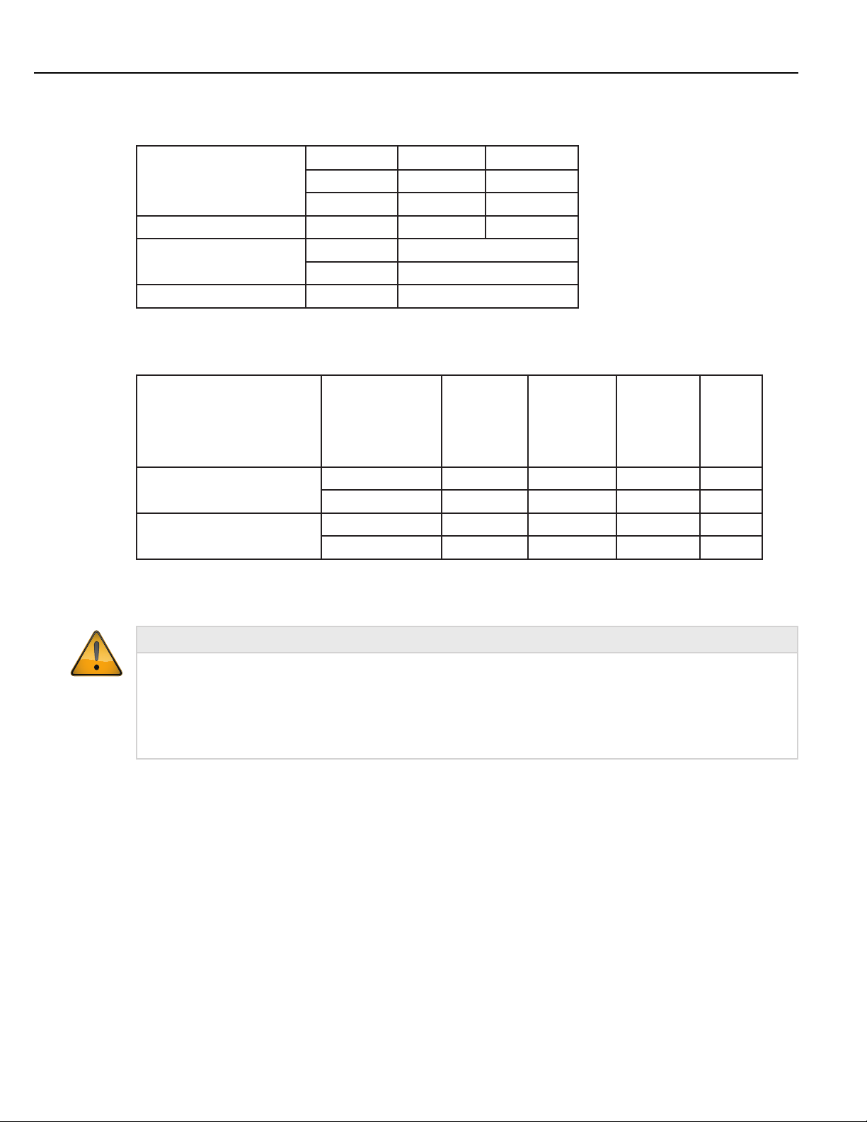
1.1 What’s Included
Included with the QB Expert Alpha controller is a power cord, plinth (for mounting), documentation (in the
envelope) and a mating connector for the I/O port. The mating connector is included so the end user may connect
wires to the controller’s I/O port to their requirements.
5
1
2
, Cleveland, OH 44143 USA
STANLEY ASSEMBLY TECHNOLOGIES
Telephone: +1 (440) 461-5500 Email: satinfo@sbdinc.com URL: http://StanleyAssembly.com
5335 Avion Park Drive
4
Item Number Description
1 QB Expert Alpha Controller
2 Plinth for mounting controller
3 Power cord
4 24 V DC I/O mating connector
3
5 Envelope with Getting Started Documentation
2
QB Expert Alpha Controller
Page 11
9
Introduction
1
4
5
2
19
3
8
11
16
POWER
TOOL
13
115/230VAC 50/60HZ
10 AMP 1/N/PE~
WARNING
!
ELECTRIC SHOCK HAZARD
To prevent injury
disconnect power cord
before removing cover
ETHERNET
I/O
AVERTISSMENT
!
RISQUE DE DECHARGE ELECTRIQUE
Pour empecher des dommages
debranches le cordon de secteur
avant d enlever la couverture
USB
SPINDLE
COM PORT
PROTECTED BY ONE OR MORE OF
THE FOLLOWING US PATENTS:
5,315,501
5,637,968
6,516,896
10
12
17
14
15
7
See Description on next page
Instruction Manual
6
FIELDBUS OPTIONS
18
3
Page 12

Controller Functions and Connections
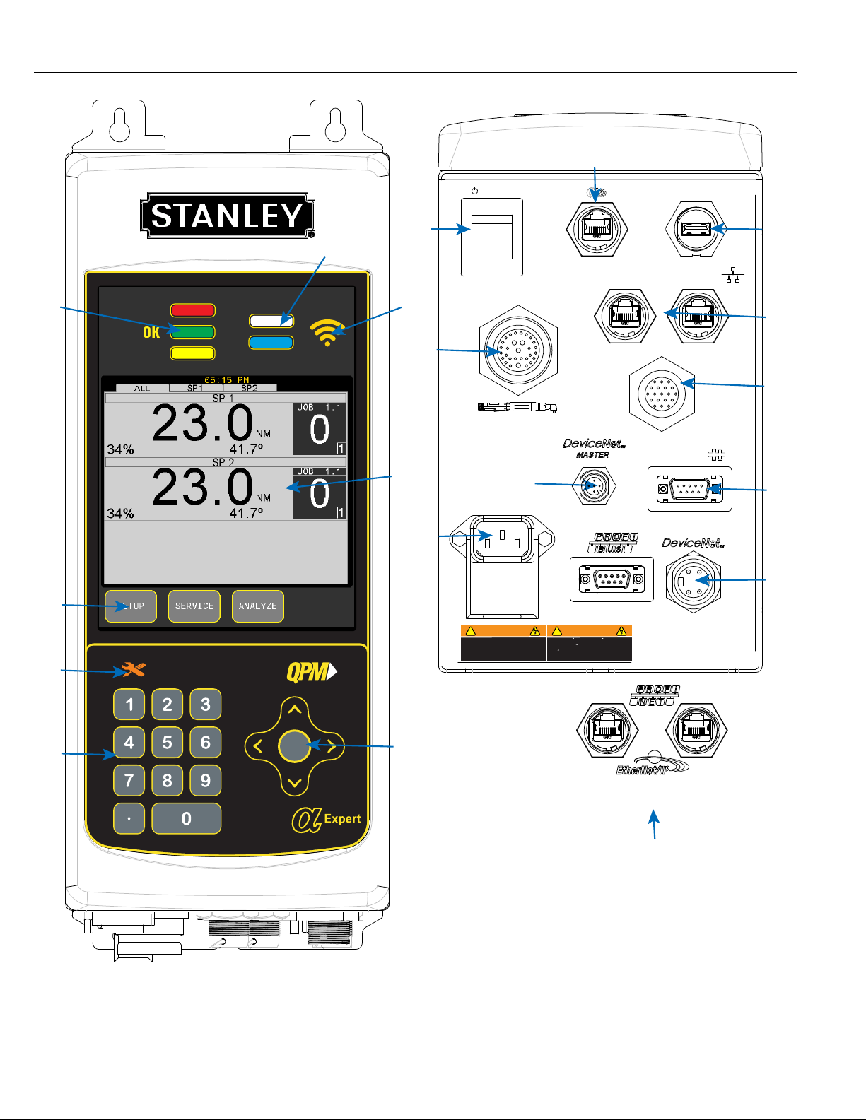
1.2 Controller Functions and Connections
This table refers to the picture on the previous page.
Item Number Functional Description
1 Red, Green, Yellow LEDs for Limits Evaluation
2 Programmable and Tool Ready LEDs
3 Display
4 Function Keys with Active Label Above
5 Maintenance Due Indicator
6 Cursor Keys with Center Button to Expand Lists
7 Numeric Keypad to Enter Numbers or Select Options
8 Power Switch
9 Alpha Toolbox Connector
10 USB Port for Data Transfer
11 Tool Connector
12 Plant/ Spindle Network Ethernet Connectors
13 Optional Master DeviceNet Connector
14 Serial Connector
15 Optional Profibus or DeviceNet Connector
16 Power Input
17 19-Pin, 24V DC Input/Output Connector
18 Optional Fieldbus Ethernet Connectors
19 Indicates WiFi Enabled (when present)
Information about these items is discussed elsewhere in this manual. Use the Table of Contents to find the page
for the item of interest. If this is an electronic document you are reading click on the item in the Table of Contents
and it will link you directly to the page. Or press CNTRL+F on the keyboard to search the document for the item
of interest.
1.3 CE Directives (Europe)
STANLEY Engineered Fastening Assembly Technologies declares that the QPM QB Expert Alpha controller
conforms to all the applicable regulations of the Machinery Directive. See the CE Declaration of Conformity that
is delivered with each QB Expert Alpha controller.
1.3.1 Machinery Directive Compliance
This product complies with the requirements of the European Machinery Directive (2006/42/EC). See the CE
Declaration of Conformity that is delivered with the product.
4
QB Expert Alpha Controller
Page 13
1.3.2 RoHS Compliance
This product and its information meets the requirements of the European Restriction of Hazardous Substances
(RoHS) Directive (2011/65/EU).
1.3.3 WEEE Compliance
This product and its information meets the requirements of the European Waste of Electrical and Electronic
Equipment (WEEE) Directive (2011/65/EU). This product is marked with a crossed trashcan, see last figure below
in section 1.5.1 Warnings and Cautions.
1.4 Regulatory Notices for Radio Transmitter
It is mandatory that national, state and local codes and standards be followed.
1.4.1 FCC Notice (USA)
This device complies with Part 15 of the FCC Rules. Operation is subject to the following two conditions: (1) this
device may not cause harmful interference, and (2) this device must accept any interference received, including
interference that may cause undesired operation.
This equipment has been tested and found to comply with the limits for a Class B digital device, pursuant to Part
15 of the FCC Rules. These limits are designed to provide reasonable protection against harmful interference
in a residential installation. This equipment generates, uses and can radiate radio frequency energy and, if not
installed and used in accordance with the instructions, may cause harmful interference to radio communications.
However, there is no guarantee that interference will not occur in a particular installation. If this equipment does
cause harmful interference to radio or television reception, which can be determined by turning the equipment
off and on, the user is encouraged to try to correct the interference by one or more of the following measures:
• reorient or relocate the receiving antenna,
• increase the separation between the equipment and receiver,
• connect the equipment into an outlet on a circuit different from that to which the receiver is connected, or
• consult the dealer or an experienced radio/TV technician for help.
This device contains transmitter module FCC ID: TE7WR702N.
Introduction
• To satisfy FCC RF exposure requirements for mobile transmitting devices, a separation distance of 20 cm
(7.87 in) or more should be maintained between the antenna of this device and persons during operation.
To ensure compliance, operations at closer distances than this are not recommended.
1.4.2 Canadian Compliance Notice
This device complies with Industry Canada license-exempt RSS standard(s). Operation is subject to the following
two conditions:
• This device may not cause interference, and
• This device must accept any interference, including interference that may cause undesired operation of the
device.
Cet appareil est conforme aux norms CNR exemptes de licence d’Industri Canada. Le
fonctionnement est soumis aux deux conditions suivantes:
• cet appareil ne doit pas provoquer d’interférences et
Instruction Manual
CAUTION
5
Page 14
Safety
• cet appareil doit accepter toute interérence, y compris celles susceptibles de provoquer un fonctionnement non
souhaité de l”appareil.
1.4.2.1 Industry Canada Notice (Canada)
Complies with the Canadian ICES-003 Cleass B specifications.
Cet appareil numérique de la classe B est conforme à la norme NMB-003 du Canada.
This device complies with RSS 210 of Industry Canada. This device meets all the requirements of the Canadian
interference-causing equipment regulations.
Cet appareil numérique de la classe B respecte toutes les exigences du Règlement sur le
matériel brouilleur de Canada.
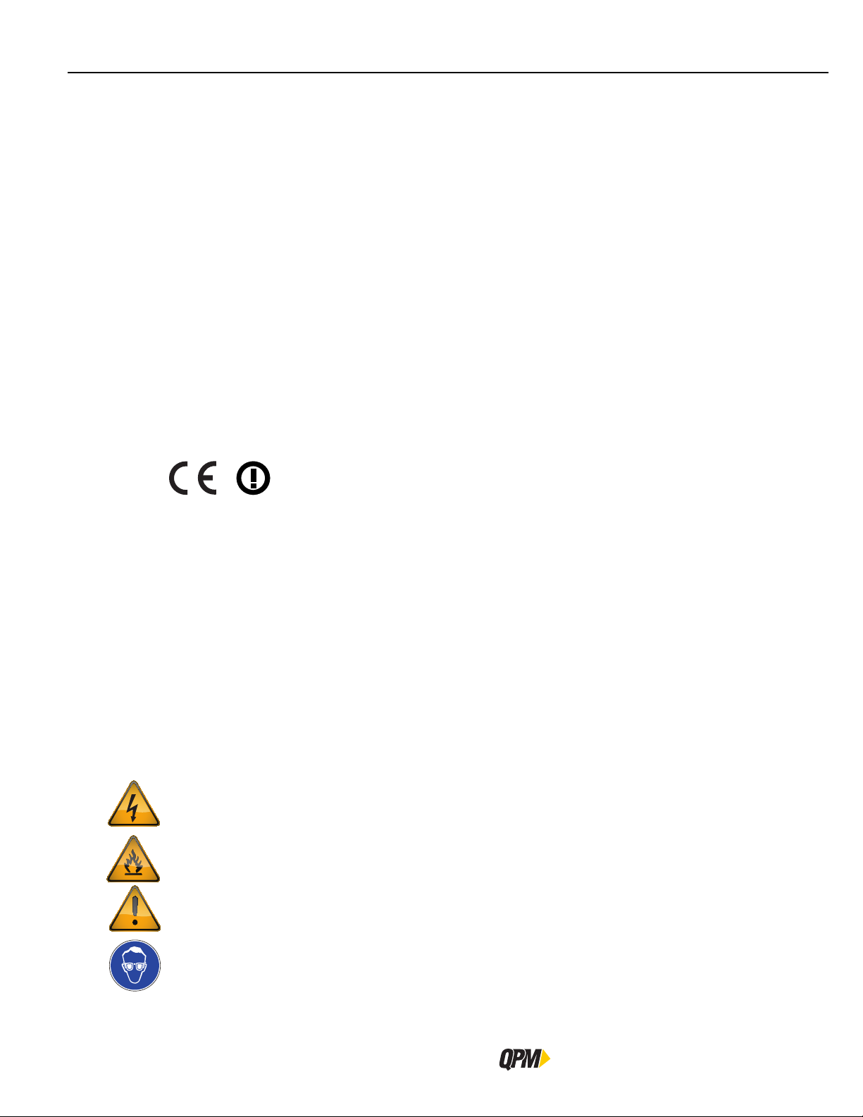
1.4.3 CE Notice (Europe)
This device has been tested and certified for use in the European Union. This product complies with the
requirements of the European Radio & Telecommunications Terminal Equipment (R&TTE) Directive (1999/5/EC).
The ‘CE’ mark has been placed on the device per the labeling requirements of the Directive.
Given that the operating frequency band is not harmonized by a few European countries, the restriction or
alert sign has been placed alongside the ‘CE’ mark as shown below. As of the date of this document, only
France has a restriction. The restriction is that, if the radio is operated outdoors in the 2450-2483.5 MHz
band, the power must be limited to 10 mW instead of 100 mW. This device is not intended for outdoor use.
1.5 Safety
1.5.1 Warnings and Cautions
The safety notices and warnings for protection against loss of life (the users or service personnel) or for the
protection against damage to property are highlighted in this document by the terms and pictograms defined
here. The terms used in this document and marked on the equipment itself have the following significance:
DANGER
WARNING
CAUTION
Indicates that death or severe personal injury will result if proper precautions are not taken.
Indicates that death or severe personal injury may result if proper precautions are not taken.
Indicates that property damage may result if proper precautions are not taken.
Indicates an electrical hazard. This icon appears as a part of a DANGER, WARNING, or CAUTION
notice.
Indicates a fire hazard. This icon appears as a part of a DANGER, WARNING, or CAUTION notice.
Indicates a general hazard. This icon appears as a part of a DANGER, WARNING, or CAUTION notice.
Indicates that eye protection should be worn. This icon appears as a part of a DANGER, WARNING, or
CAUTION notice.
6
QB Expert Alpha Controller
Page 15
Introduction
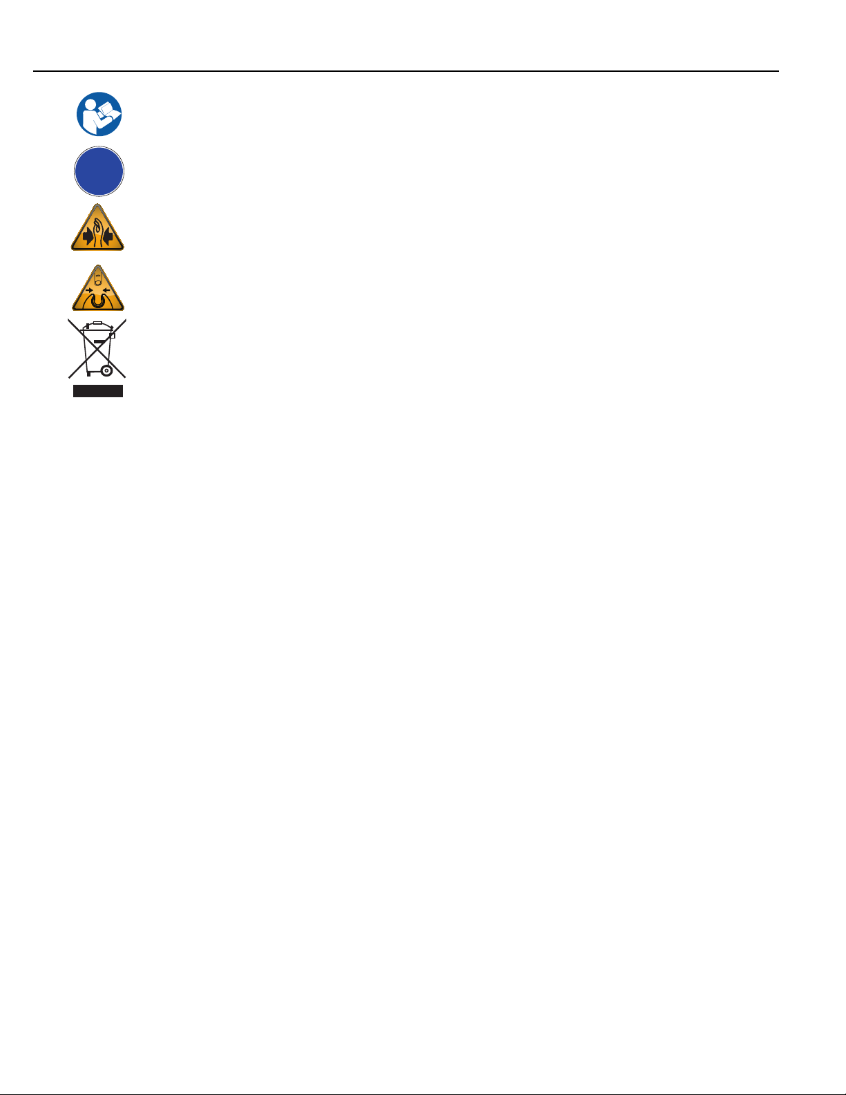
!
Read and understand all the safety recommendations and all operating instructions before operating
tools and controllers.
Indicates an item of special interest.
Indicates a pinch point hazard. This icon appears as a part of a DANGER, WARNING, or CAUTION
notice.
Indicates an open wrench pinch point hazard. This icon appears as a part of a DANGER, WARNING, or
CAUTION notice.
Indicates an environmental hazard. Do not throw equipment into the normal housekeeping refuse bin.
Instruction Manual
7
Page 16

Safety
1.5.2 General Power Tool Safety Warnings
These warnings are required by EN 60745.
Read all safety warnings and all instructions. Failure to follow the warnings and instructions may result in
electric shock, fire and/ or serious injury.
Save all warnings and instructions for future reference.
The term “power tool” in the warnings refers to mains-operated (corded) power tool or battery-operated
(cordless) power tool.
1. Work Area Safety
a.) Keep work area clean and well lit. Cluttered or dark areas invite accidents.
b.) Do not operate power tools in explosive atmospheres, such as in the presence of
flammable liquids, gases or dust. Power tools create sparks which may ignite the dust or fumes.
c.) Keep children and bystanders away while operating a power tool. Distractions can cause you
to lose control.
2. Electrical Safety
a.) Power tool plugs must match the outlet. Never modify the plug in any way. do not use
any adapter plugs with the earthed (grounded) power tools. Unmodified plugs and matching
outlets will reduce risk of electric shock.
b.) Aoid body contact with earthed or grounded surfaces, such as pipes, radiators, ranges and
refrigerators. There is an increased risk of electric shock if your body is earthed or grounded.
c.) Do not expose tools to rain or wet conditions. Water entering a power tool will inrease the risk
of electric shock.
d.) Do not abuse the cord. Never use the cord for carrying, pulling or unplugging the power
tool. Keep cord away from heat, oil sharp edges or moving parts. Damaged or entangled
cords increase the risk of electric shock.
e.) When operating a power tool outdoors, use an extension cord suitbable for outdoor use.
Use of a cord suitable for outdoor use reduces the risk of electric shock.
f.) If operating a power tool in a damp location is unavaoidable, use a residual current device
(RCD) proteted supply. Use of an RCD reduces the risk of electric shock. The term “residual
current device(RCD)” may be replaced by the term “ground fault circuit interrupter (GFCI)” or “earth
leakage circuit breaker (ELCB)”.
3. Personal Safety
a.) Stay alert, watch what you are doing and use common sense when operating a power tool.
Do not use a power tool while you are tired or under the influence of drugs, alchohol or
medication. A moment of inattention while operating power tools may result in serious personal
injury.
b.) Use personal protective equipment. Always wear eye protection. Protective equipment such
as dust mask, non-skid safety shoes, hard hat, or hearing protection used for appropriate conditions
will reduce personal injuries.
c.) Prevent unintentional starting. Ensure the switch is in the off-position before connecting
to power source adn/ or battery pack, picking up or carrying the tool. Carrying power tools
with your finger on the switch or energising power tools that have the switch on invites accidents.
d.) Remove any adjusting key or wrench before turning the power tool on. A wrench or key left
attached to a rotating part of the power tool may result in personal injury.
WARNING
8
QB Expert Alpha Controller
Page 17

Introduction
WARNING
Continued:
e.) Do not overreach. Keep proper footing and balance at all times. This enables better control
fo the power tool in unexpected situations.
f.) Dress properly. Do not wear loose clothing or jewellery. Keep your hair, clothing and
gloves away from moving parts. Loose clothes jewellery or long hair can be caught in moving
parts.
g.) If devices are provided for the connection of dust extraction and collection facilities,
ensure these are connected and properly used. Use of dust collecton can reduce dust-related
hazards.
4. Power Too Use and Care
a.) Do not force the power tool. Use the correct power tool for your application. The correct
power tool will do the job better and safer at the rate for which it was designed.
b.) Do not use the power tool if the switch does not turn it on and off. Any power tool that
cannot be controlled with the switch is dangerous and must be repaired.
c.) Disconnect the plug from the power source and/ or the batatery pack from the power
tool before making any adjustments, changing accessories, or storing power tools. Such
preventive safety measures reduce the risk of starting the power tool accidentally.
d.) Store idle power tools out of the reach of children and do not allow persons unfamiliar
with the power tool or these instructions to operate the power tool. Power tools are
dangerous in the hands of untrained users.
e.) Maintain power tools. Chek for misalignment or binding of moving parts, breakage of
parts and any other condition that may affect the power tool’s operation. If damaged,
have the power tool repaired before use. Many accidents are caused by poorly maintained
power tools.
f.) Keep cutting tools sharp and clean. Properly maintained cutting tools with sharp cutting edges
are less likely to bind and are easier to control.
g.) Use the power tool, accessories and tool bits etc. in accordance with these instructions,
taking into account the working conditions and the work to be performed. Use of the power
tool for operations different from those intended could result in a hazardous situation.
5. Service
a.) Have your power tool serviced by a qualified repair person using only identical
replacement parts. This will ensure that the safety of the power tool is maintained.
Instruction Manual
9
Page 18

Safety
1.5.3 Safety Instructions for QB Expert Alpha Controllers
WARNING
To Avoid Injury:
• Save these instructions for future reference.
• Read and understand all the safety recommendations and all operating instructions before operating tools
and controllers. Failure to follow all instructions listed below may result in electric shock, fire and/or serious
personal injury.
• Train all operators in the safe and proper use of power tools. Operators should report any unsafe condition
to their supervisor.
• Follow all safety recommendations in the manual that apply to the controllers, tools, battery packs and
chargers being used and the nature of the work being performed.
• Verify that all warning labels illustrated in this manual are readable. Replacement labels are available at no
additional cost from STANLEY Assembly Technologies.
• Only allow suitably qualified personnel to install, program, or maintain this equipment and or system. Follow
all manufacturer installation instructions and applicable regulatory electrical codes and safety codes.
• These persons must be knowledgeable of any potential sources of danger and maintenance measures as set
out in the Installation, Operations, and Maintenance manual.
• This product must be transported, stored, and installed as intended, and maintained and operated with care
to ensure that the product functions correctly and safely.
• Persons responsible for system planning and design must be familiar with the safety concepts of automation
equipment.
• Install tools in dry, indoor, non-flammable, and non-explosive environments only–Humidity: 0 to 95% noncondensing and Temperature: 32 to 122 ºF (0 to +50 ºC).
• Do not install worn, damaged, or modified equipment that may be unsuitable for safe use.
• Controller plugs must match the outlet and must be earth grounded. Never modify a plug in any way or use
any adaptor plugs.
• Avoid body contact with electrically energized surfaces when holding a grounded tool.
• Prior to connecting a power source, always ensure the tool or controller is turned off.
• Limit controller access to trained and qualified personnel. Lock controller cabinets.
• Only use equipment and accessories specifically designed to operate with STANLEY assembly tools and use
them only in the manner for which they are intended.
• Store idle tools and accessories in a safe location accessible only by trained persons.
• Disconnect power source (battery, electricity, etc.) from tool or controller prior to making adjustments,
changing accessories, or storing.
• Prior to operation, always check and test tools and accessories for damage, misalignment, binding or any other
condition that may affect operation. Maintenance and repair should be performed by qualified personnel.
10
• Do not operate tools in or near explosive environments or in the presence of flammable liquids, gases, dust,
rain or other wet conditions.
• Keep the work area clean, well lit and uncluttered.
• Keep unauthorized personnel out of the work area.
QB Expert Alpha Controller
Page 19
1.6 Specifications
1.6.1 Physical and Environmental Ratings
Width: 6.0 inches 152 mm
Dimensions:
Weight: 18 pounds 8.2 kgrams
Operating Conditions:
Ingress Protection Rating: IP54 NEMA 3
1.6.2 Electric Service Ratings
These are the minimum electric service ratings for the QB Expert Alpha controller and the tools it can control.
Height: 16.0 inches 406 mm
Depth: 10.4 inches 264 mm
Temperature: 32 to 122 ºF (0 to +50 ºC)
Humidity: 0 to 95 % non-condensing
Introduction
Tool Model: E02-E23
EA23
EB02−EB22
EC02−EC22
100 − 126.5V AC 15 A 15 A 20 A * 30 A *
Current for Supply Voltage:
200 − 253V AC 10 A 10 A 10 A 10 A
Standby 0.2 A 0.2 A 0.2 A 0.2 A
Power Consumption:
Continuous 0.3 kVA 0.7 kVA 1.0kVA 2.2 kVA
* 200−240V AC highly recommended
1.6.3 E-Stop Precaution
WARNING
INTEGRATED E-STOP CIRCUIT NOT PRESENT
To Avoid Injury:
• When a QB Expert Alpha controller connects to a tool where a fault can result in personal injury or substantial
damage to property, an E-stop circuit is required. An E-stop circuit must be created in the external electrical
service supply line.
1.6.4 Tool Speed and Torque Scatter Versus Electric Supply
The minimum electric supply voltage required to attain catalog speeds is 104V AC or 208V AC depending which
supply voltage system is used. Supply voltages above these minimums should have NO effect on reducing speed.
Supply voltages BELOW these minimums will reduce maximum free speed proportionally; actual speed should be
the LOWER of the speed command or the maximum attainable speed. Slow Seek and downshift speeds should
not be affected unless they are set close to maximum attainable speed. Similarly torque scatter should NOT be
affected by reduced supply voltages.
E33-E34
EA33−EA34
EB33-EB34
EC33-EC34
E44-E45
EB44-EB45
EC44
E55
EB55
1.6.5 Tool Temperature Versus Electric Supply
Supply voltages that remain within recommended limits during the fastening cycle will provide shortest cycle
times and lowest tool temperatures. Tool temperatures on applications with moderate to high prevailing torque
levels and/or low (i.e. soft) torque rates stand the most chance of being negatively impacted by low or “sagging”
Instruction Manual
11
Page 20

Installation Instructions
supply voltages. Voltage “sag” is a reduction in voltage which occurs when high current draw causes a voltage
drop in the supply wiring which reduces voltage at the power plug and consequently reduces maximum attainable
tool speed under load. Fuses and breakers are also more likely to blow or trip under these conditions. To minimize
these effects, always connect the system to electric service that meets the recommended supply service ratings.
1.7 Installation Instructions
ELECTRICAL HAZARD
To Avoid Injury:
• This product should be located away from heat sources such as radiators or other devices that produce heat.
• This product should not be subjected to vibration or shock or in close contact with water or other liquids.
• To minimize electrical interference, place the module as far away from possible sources of electrical noise,
such as arc welding equipment.
• Install tools and controllers in dry, indoor, non-flammable, and non-explosive environments only.
• Do not use this product near water, for example near a washbowl, wet basement, or the like.
• Avoid body contact with electrically energized surfaces when holding a grounded tool.
Please refer to the picutres of a plinth and mounting of the QB Expert Alpha controller on the next two pages.
Plinths connect to each other with four 10-32 machine screws through openings on the top and right side to
threaded openings on the bottom and left side. When mounting plinths are placed next to each other, the centerto-center distance between the mounting holes in different plinths is 2” (50.8 mm). When mounting plinths are
place one above another, the center-to-center distance between the mounting holes in different plinths is 6”
(152.4 mm).
Install the QB Expert Alpha Controller either directly to the wall or to a plinth (part number 21E204300).
Fasteners through four mounting holes secure plinths to a wall or other surface. Plinths can be connected using
10-32 threaded holes on the bottom and left side and through holes on the top and right side.
Make sure the bolts of the barrel-latches [5] on the plinth are retracted. Place the lower flange of the QB Expert
Alpha controller [1] into the lip [2] on the plinth.
Align the slot [3] in the flange with the lower mounting-pin [4] on the plinth while placing. Rotate the top of the
controller back towards the plinth.
Place the openings on the upper flange of the controller [6] over the upper mounting pins [7] on the plinth.
Release the bolts on the barrel-latches [5] making sure the bolts enter the two barrels [8] on the controller.
Connect the QB Expert Alpha Controller to a power source.
Connect one end of the tool cable to the tool and the other end to the QB Expert Alpha controller and press the
power switch on the controller.
The controller displays a language list at the first boot up. Press the up/down arrows to select a language, then
press either NEXT from the interactive menu button or use the Toggle button to save the selection.
The controller next prompts for regional settings like Time Zone, Time and Date. Follow the prompts until the run
screen appears indicating the controller is ready for programming and operation.
WARNING
12
QB Expert Alpha Controller
Page 21
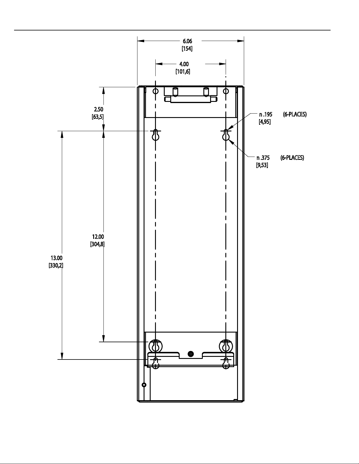
6.06
18.00
[457,2]
[154]
4.00
[101,6]
Introduction
13.00
[330,2]
2.50
[63,5]
12.00
[304,8]
n .195 (6-PLACES)
[4,95]
n .375 (6-PLACES)
[9,53]
Instruction Manual
Plinth 21E204300
13
Page 22
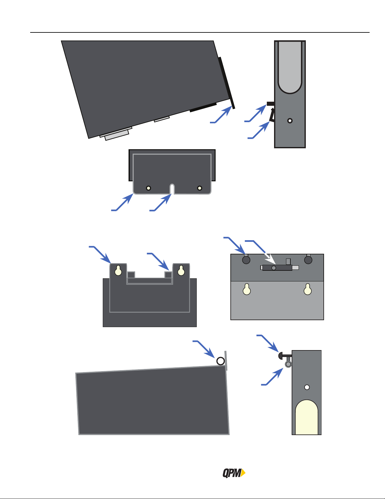
6
1
8
3
1
7
4
2
5
14
8
7
5
Mounting QB Alpha Expert Controller onto Plinth
QB Expert Alpha Controller
Page 23

Introduction
Instruction Manual
15
Page 24

Page 25

QB Expert Alpha Controller
Controller Operation
2
Data Storage
Input and Output Functions
Spoftware
Embedded PLC
Networking
Navigation
Display
Faults
Messages
Page 26

Data Storage
2 QPM QB Expert Alpha Controller
The QB Expert Alpha controller is a modular, high-end, full-featured controller for QPM DC servo power tools with
torque transducers. It will control any QPM E, EA, EB or EC series servo motor-powered tool. It utilizes closed
loop control of torque, speed and angle so that it can perform various routines for the tool to secure each fastener
with the highest quality results. The high precision torque and angle sensors in the tool provide feedback to the
QB Expert Alpha controller’s digital control circuit. This circuit compares the feedback values to the programmed
values and adjusts the tool’s power and speed values to maintain the programmed speed on the output of the
tool until the fastener has achieved the programmed target torque and/or angle value. Once the programmed
value is sensed the control circuit turns off the tool leaving the fastener with the desired amount of preload or
clamping force.
The QB Expert Alpha controller is certified to IP54 level to withstand the dust, dirt and liquids found in industrial
facilities. Installing into other panels is not necessary.
QB Expert Alpha controllers have an IEEE 802.11b/g/n radio so that the QPM Cordless line of tools may be added
to it as well. Software version 5.2.5 is the first software version to support the QPM cordless tools.
The QB Expert Alpha controller is designed to be a lead controller in a multiple tool system. Multiple systems of
up to 24 spindles can be configured and managed by the QB Expert Alpha controller. Trailing controllers used in
multiple spindle systems can be QB Advanced Alpha or QB Node Alpha or the new QPM Cordless tools.
The QB Expert Alpha controller can be used as a standalone system as it runs its own tool.
2.1 Data Storage
Data associated with 30,000 fastening cycle results and 10,000 traces is stored in the QB Expert Alpha controller.
This data is retrieved with a USB memory stick or Alpha Toolbox. SPC analysis is performed by the QB Expert
Alpha controller on the stored data.
2.2 Input and Output Functions
Bolt Count or Error Proofing functions are an integral part of the QB Expert Alpha controller’s functions. Its eight
inputs and eight outputs on the 24V DC I/O connector support these functions to provide expert plant integration
to external devices such as a PLC.
The inputs and outputs are assignable, and configurable.
The QB Expert Alpha controller supports other bus types such as ModbusTCP, which is standard, plus optional
Ethernet/IP, Profibus, ProfiNet and DeviceNet. DeviceNet can be ordered as either a scanner or device.
2.3 Software
Any computer with a modern web browser connected wirelessly or with an Ethernet cable on the Ethernet
network port, or the ATB port, is used to view the QB Expert Alpha controller’s web-based application called
Alpha Toolbox. Software is not loaded onto a computer to access the data or configure the controller. Alpha
Toolbox updates come with the controller updates.
2.4 Embedded PLC
The QB Expert Alpha controller comes with a software PLC that emulates many commands and features of the
Allen Bradley SLC-500 series controller. Anyone with logic writing skills and the Alpha Toolbox PLC Editor can
program a logic file to add more versatility to the already abundant features of the QB Expert Alpha controller.
2.5 Networking
Ethernet and the Internet Protocol using Transport Control Protocol are a powerful and robust means of moving
data from one computer to another. Many end users rely on it to collect information from plant floor equipment.
The QB Expert Alpha controllers support the XML (2.0, 2.1), PFCS, NPL, TOOLSNET, OPEN and FORD protocols.
18
QB Expert Alpha Controller
Page 27
For those that haven’t switched to this more robust means of collecting data, the QB Expert Alpha controller
supports the PFCS, OPEN and Toyota PI protocols over a serial connection.
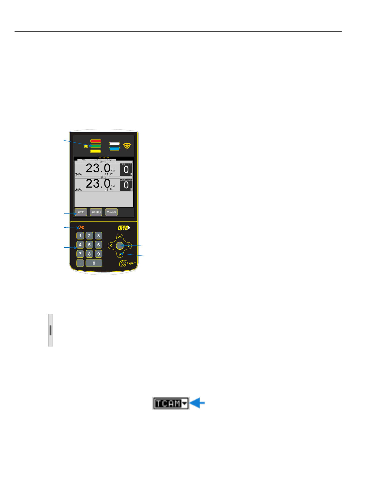
2.6 Navigation
The QB Expert Alpha controller’s four navigation and input areas facilitate menu navigation, selection and data
input:
– Interactive Menu buttons
– Arrows and Toggle button
– Keypad
– Touch screen
5
1
6
4
Controller Operation
Labels for the four interactive menu buttons [1] change with menu selection.
If the label is blank, the button has no function for the current screen.
The up/down arrows [2] navigate menu and character selections; the left/
right arrows enable backspace and space, as well as navigate between tabs.
The Toggle button [3] switches between modes and selects/accepts choices
(synonymous with OK interactive menu button).
The numeric keypad [4] facilitates data input and menu selection (where
applicable) and Job/Task selection when enabled.
The five LEDs [5] specify status of the fastening cycle for spindle 1:
– Red indicates high torque/angle;
– Green indicates an OK fastening cycle;
– Yellow indicates low torque/angle;
– White is programmed by the embedded PLC, and
3
2
– Blue indicates when the tool is enabled to run.
The Orange Wrench icon [6] indicates preventive maintenance is due on the
tool of spindle 1.
2.7 Display
2.7.1 Scroll Bar
A scroll bar appears on the right of the screen when more items are available than the display allows to view at
one time. The black scroll bar indicates which list items are currently displayed. No scroll bar means all items are
currently displayed.
To navigate between menu items, use the up/down arrows or, if available, use the keypad to identify the
corresponding menu item number.
2.7.2 Dropdown
A dropdown arrow appears to the right of menu items with multiple choices. To view choices, highlight the menu
item using the up/down arrows then use the Toggle button to expand the dropdown. Use up/down arrows to
scroll and the toggle or interactive menu button to select/accept.
Instruction Manual
19
Page 28
Display
2.7.3 Menu Tree
A menu tree appears beside related menu items.
2.7.4 Tabs
Tabs appear at the top when multiple menu selections exist. To navigate between tabs, use the left/right arrows.
The active tab is white; inactive tabs are grey.
2.7.5 Character Scrollbar
This scrollbar enables adding: a-z, A-Z, 0-9, space, _, -, &, *, $, #, @, !, and a period (language and/or field
determines character availability). The up arrow [1] and down arrow [3] direct scrolling with the active character
[2] displayed between. Use the QB Expert Alpha controller’s up/down arrows to scroll through character choices.
The left arrow backspaces. The right arrow moves one position to the right to input the next character. Push
Toggle button or OK interactive menu button to accept entry.
The following screens contain the character scrollbar option: ALL, Job (Name), Task (Name) Step (Name), System
(Name General), System (Users), WIFI (SSID, Password).
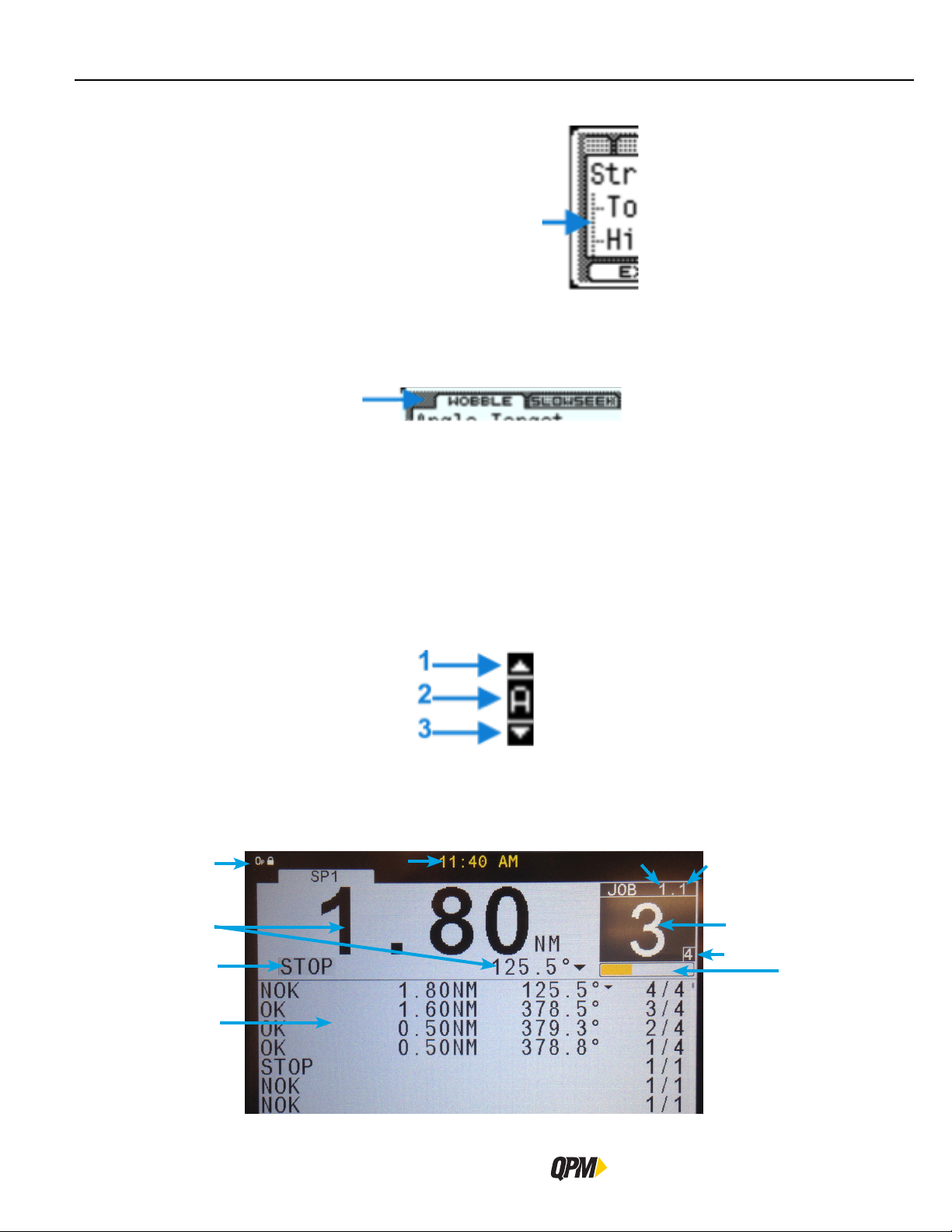
2.7.6 Run Display
The Run screen displays normal operating information one spindle at a time. To display a different spindle on a
multiple spindle unit press the right or left arrow key to switch to the next spindle tab.
1
2
8
9
20
10
6
7
4
3
11
QB Expert Alpha Controller
Page 29
Controller Operation
Icons identify events [1], see list below. Displays last torque and angle readings with units, when a tool is connected
[2]. Up/down arrows next to the torque or angle value indicate the last fastening cycle NOK status whether it
exceeded (up) or did not achieve (down) torque or angle limits.
Identifies the active Job [6] and active Task [7]. Identifies Target batch count [3] and Accumulated bolt count [4]
for the active Job. The side scroll bar indicates events are available in the Event Log. Press the down arrow to
view the events. The number of fastening cycle attempts indicator is below the bolt count box. The run screen
displays unless other programming functions [5] are in use. A Shutoff code is also displayed when applicable [8].
The display also has the current time [10] for the specified region and fastening cycle history in the Fastening cycle
Log [9].
This [11] portion of the screen changes to an orange bar with white background when either Limit Rejects or Job
Timer parameters are used. The orange bar increments in one division of the width equal to the Reject Count value
each time a NOK cycle occurs. This bar also acts as a progress bar for the Job Timer to indicate the progress of
the timer.
The time display [10] will change in the following manner:
When a Part ID is received the time will change to the Part ID for 5 seconds and then return to the clock.
If the Job or Task has been selected the Job Name:Task Name appear on the screen until the batch count (Job) has
been completed and then returns to the clock.
The display background color turns red in the event of a fault; see section “2.8 Faults” on page 25.
The run display changes to indicate the step in which the tool stopped (providing it did not stop during the audit
step).
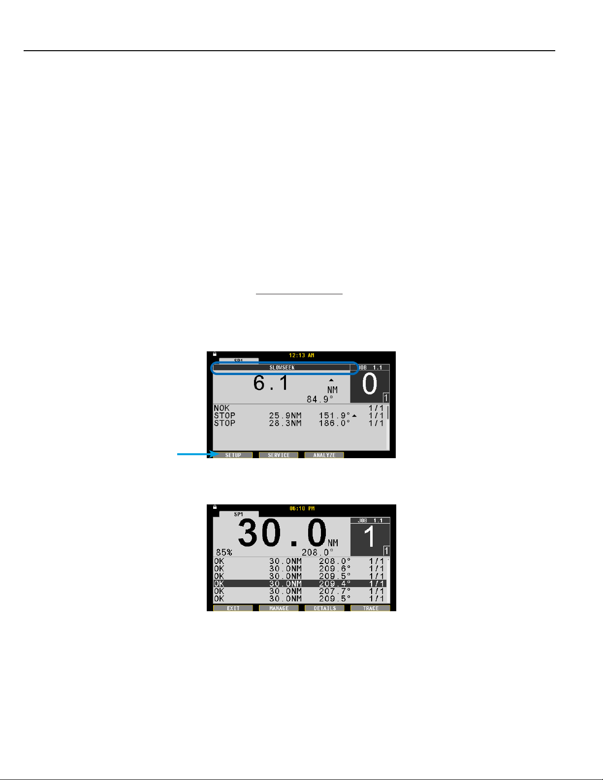
The Fastening Cycle Log [9] lists the fastening cycles that have occurred in the QB Expert Alpha controller. While
viewing the Run Display press the down arrow to access the Fastening Cycle Log.
Use the up/down arrow keys to scroll through the data listed chronologically (newest at the top, oldest at the
bottom). Each line identifies a fastening cycle. The first column indicates the fastening cycle status or shutoff
code. The second column indicates the achieved torque during the fastening cycle. The third column indicates the
achieved angle during the fastening cycle. The fourth column indicates the working bolt count.
2.7.7 Fastening Cycle Log
Press the interactive MANAGE button after selecting a data line to display the MANAGE dialog box.
Instruction Manual
5
21
Page 30
Display
Use the up/down arrow keys and the interactive OK button, or the Toggle button, or the number keys, to select
the action required.
Export Rundowns will transfer all fastening cycle data to the USB memory stick after choosing a file name.
Export Trace will transfer fastening cycle trace data to the USB memory stick after choosing a file name. Choose
between the selected trace, the number of traces in the population size or all traces to be exported. When
exporting the SELECTED trace it exports as a comma seperated value file. If POPULATION or ALL are selected the
appropriate number of traces are placed into a zip file before exporting. If selecting All, be aware it will take a
significant amount of time before all traces are put into the zip file and exported.
Delete Rundowns will delete all fastening cycle and trace data from the QB Alpha Expert controller. This action
cannot be undone.
Press the interactive YES button to delete the data. Press the interactive NO button to cancel the delete action.
Use the following sequence to save a Rundown or Trace file.
Insert a USB memory stick into the USB port on the bottom of the QB Expert Alpha controller. Use the down
arrow to select the Name field. Use the Toggle button to enter edit mode. Use the left arrow to delete the name.
Use the up/down arrows or the numeric keypad to write a new file name if required. Press the interactive OK
button or the Toggle button to accept the file name.
Press again to save the file to the USB memory stick.
Press the interactive EXIT button to return to the Run screen.
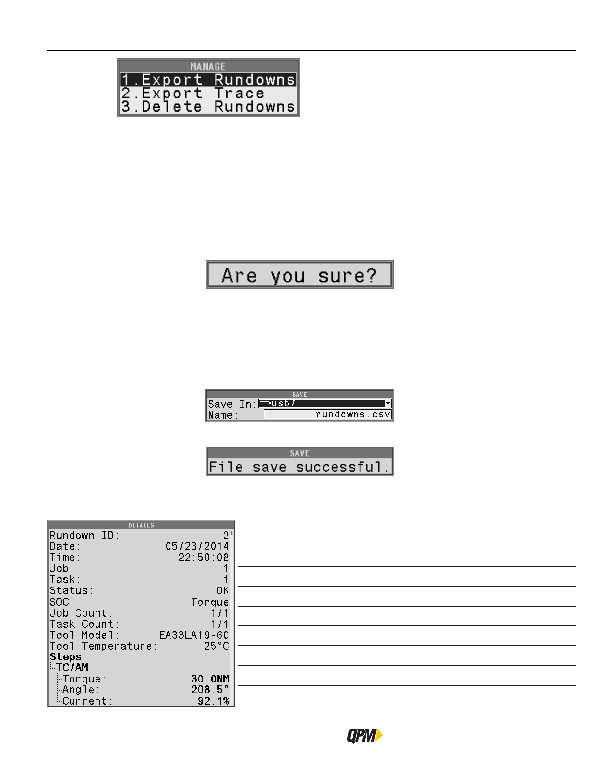
2.7.7.1 Fastening Cycle Details
Not all items are shown
Press the interactive DETAILS button or the Toggle button after selecting a data line
to display the details.
Details about the event and when it occurred are listed.
Rundown ID: The sequential number of the fastening cycle data
Date: The date the fastening cycle was ran.
Time: The time the fastening cycle completed.
Job: The active Job number in which the fastening cycle ran.
Task: The active Task number in which the fastening cycle ran.
Status: The overal status of the fastening cycle.
22
QB Expert Alpha Controller
Page 31

Controller Operation
SOC: Shutoff Code, see section “2.7.7.2 Shutoff Codes” on page 23
Job Count: The active fastener number for the Job.
Task Count: The active fastener number for the Task.
Tool Model: The model number of the tool used during this fastening cycle.
Tool Serial: The serial number of the tool used during this fastening cycle.
Tool
Temperature:
Part ID: The value in the Part ID buffer when the fastening cycle ran.
Steps: List the steps used during the fastening cycle. The Audit step
TC/AM The Strategy or Smart Step used in the current step.
Torque: The Torque value achieved in the current step.
Angle The Angle value achieved in the current step.
Current The Current value achieved in the current step.
Rate The Rate value achieved in the current step (if enabled)
Deviation The Rate Deviation achieved in the current step (if enabled)
Use the up/down arrows to scroll through the Details.
Press the interactive BACK button to return to the Fastening Cycle Log.
2.7.7.2 Shutoff Codes
Shutoff Codes on the display indicate why a fastening cycle terminates prior to completion.
Shutoff Code Description
The temperature of the tool at shutoff.
values are in Bold.
TIME Fastening cycle time exceeds programmed Cycle Abort time value.
STOP Spindle stopped by either the operator or other device.
>115% Spindle stopped due to torque achieving greater than 115% torque limit for the tool.
FAULT The tool shutoff due to a Fault. See section “2.8 Faults” on page 25.
STALL Spindle stopped due to a stall.
SYNC Spindle failed fastening cycle due to a synchronization error.
T1≠T2 Primary and secondary redundant transducer values are outside comparative limits.
A1≠A 2 Primary and secondary redundant angle values are outside comparative limits.
TD Spindle stopped due to torque dropping below Torque Drop Threshold
YIELD Spindle stopped due to bailout on detecting yield during an Angle Control strategy.
[T] A torque/angle window violation for the Torque Monitoring portion of the fastening cycle.
RATE
I Current has exceeded the High Current Limit or not achieved the Low Current Limit.
Instruction Manual
Torque Rate has exceeded the High Limit or not achieved the Low Limit during a Rate
Monitoring portion of the fastening cycle.
23
Page 32

Display
2.7.7.3 Fastening Cycle Trace
Press the interactive TRACE button after scrolling through the log and highlighting a particular line. A Torque vs.
Time trace screen is drawn for the highlighted line.
Press the third interactive menu button to change the trace axes.
Use the up/down arrow keys and the interactive OK button or the Toggle button, or the number keys, to select
the type required.
1. Torque – Torque vs. time
2. Angle – Angle vs. time
3. Torque/Angle – Torque vs. Angle
4. Speed – Tool Speed vs. time.
Press the interactive BACK or EXIT buttons to leave the trace screen.
2.7.8 Keypad Mode
When Keypad Mode is set to Job or Task Select (see “3.1.4.1 General Tab” on page 60) at the run screen press
the Toggle button or a number on the keypad. A Job/Task window opens. Use the numbers on the keypad to
type in a Job/Task to be selected to run. Use the toggle or interactive OK button to accept and switch controller
operation to the selected Job/Task number.
When the Keypad Mode is set to PART ID (see “3.1.4.1 General Tab” on page 60) at the run screen press the
Toggle button or a number on the keypad. A PART ID window opens. Use the up/down arrows to write a character,
then the right arrow to move to the next character value to use as the PART ID. The numeric keypad may also be
used to write numbers as PART ID. Press the OK interactive menu button to save it. The limit is 32 characters.
2.7.9 Controller Display Icons
The QB Expert Alpha Controller has Icons in the upper left corner of the screen to indicate the following:
Icon Status Description
24
Locked A password is required to make edits.
Unlocked Edits are possible, automatically re-locks in time.
Busy/working Wait for icon to clear before continuing.
QB Expert Alpha Controller
Page 33

Controller Operation
Icon Status Description
Fault; system not operable Check the run screen for Fault message.
2.8 Faults
Remote User
Audi Command Port Connected
Audi Results Port Connected
PFCS Solicited Port Connected
PFCS Un-Solicited Port Connected
OPEN Connected The controller is connected to an OPEN protocol server.
Toolsnet Connected The controller is connected to a Toolsnet protocol server.
ToytotaPI Connected The controller is connected to a ToyotaPI protocol server.
The display background color in normal operation is white. In the event of a fault, the spindle display and the time
display backgrounds turn red and the fault description appears on screen. The background color reverts to original
only when the fault is cleared.
A user is editing the parameters in the controller
remotely, i.e. through Alpha Toolbox.
The controller is connected to an AUDI XML protocol
server on the Command port.
The controller is connected to an AUDI XML protocol
server on the Results port.
The controller is connected to a PFCS protocol server on
the Solicited port.
The controller is connected to a PFCS protocol server on
the Un-Solicited port.
Here is a list of the Faults in the QB Expert Alpha controller:
Total Current – the controller software limits the current applied to any tool
Overcurrent Fault!
GFI Fault!
Logic Voltage Fault!
Position Feedback Fault!
Transducer Span Fault!
Transducer Zero Fault!
based on what the tool can handle. This fault is asserted if the total current
applied is greater than allowed.
The Ground Fault Interrupter has exceeded its current trip point. A current
detector monitors the current through the three phases of the motor and asserts
this fault when the total current applied to the tool does not equal the total
current returned from the tool. All phases are turned off immediately to protect
the controller from shorts at the tool end.
The controller monitors the +5VDC, -5VDC and +12VDC of its onboard Power
Supply. This fault is asserted when those voltages fall outside of nominal range.
The controller is constantly monitoring the resolver zero and span points and
asserts this fault if they go outside specification.
This fault is asserted when the transducer zero point has shifted far enough to
prevent a full scale reading from the transducer.
This fault is asserted when the transducer zero point has shifted far enough to
prevent drift compensation at the zero point.
Instruction Manual
25
Page 34

Messages
Temperature Fault!
This fault is asserted when the tool temperature detector has reached the
temperature limit set by the Temperature Limit parameter. It resets after detected
temperature has dropped by 5°C.
Unrecognized Tool!
Tool Communications! The controller is not communicating to a tool.
Transducer Current Fault!
Unsupported Tool!
Servo Connection Fault!
Spindle Communications The lead controller loses communications with a trailing spindle controller.
2.9 Messages
Messages appear on the screen when certain non-critical conditions exist. They may appear on any screen at any
time.
Communication Fault
Count Fault
The controller is communicating to the tool but does not recognize the model
number written in the tool memory board.
Transducer current has fallen outside nominal values. For EA, EB and EC series
tools that is 4.16 mA +/- 75% (1 to 7mA).
The wrong tool type has been connected to the controller. The Alpha controller
cannot run the tool that is connected.
The CPU has lost communication to the DSP on the Logic board. This may
happen on a reboot after and upgrade as the CPU resets before the DSP.
Used for Toyota PI protocol only. Controller has lost communications to the PI
box.
Used for Toyota PI protocol only. Controller and PI box have a bolt count
mismatch.
Program Fault
Tool Update Failed Controller failed to update the tool configuration.
PLC Message A user defined message controlled by the internal PLC.
Invalid PLC File Appears when an invalid PLC file is imported into the controller.
Identifying Spindle
Used for Toyota PI protocol only. More Fastening cycles were performed than the
PI box expected.
Appears when the Expert is identifying a trailing spindle when the trailing
spindle connects or when the interactive IDENTIFY button is pressed.
26
QB Expert Alpha Controller
Page 35

Tool Disabled
Controller Operation
Along with the onscreen indication, the blue light on the controller and tool MFP
extinguishes and the STOPPED output asserts.
Tool Disabled Explanations:
Undefined Task – The selected Task is not programmed to run an audit step;
select another Task or program currently selected Task.
Invalid Job/Task – Appears when a Job or Task number less than one or greater
than 255 is selected.
Network Protocol – The plant control system issued a Stop via a network
protocol. Wait for the protocol to remove the Stop command.
Error Proofing – Error Proofing is turned on and either a Batch count has been
met, or the Job has not been reset. Reset with a Job Reset input.
Stop Issued – An Input is disabling the tool; remove the Stop input. May also be
caused by Job/ Task Verify inputs not matching selected Job/ Task.
System Initializing – The controller is booting up, please wait.
Cycle Lock-out – The Cycle Lockout timer is active, wait for it to reset.
Reject Count Exceeded – Indicates the Reject Count has been exceeded.
Internal PLC – The internal PLC is commanding the tool to STOP.
Not Armed – There are two things that can cause this event:
1. Tubenuts – By default tubenut tools require arming by tapping the MFB
before the trigger is pressed to run the tool.
2. Reset Reject – The fastening cycle is NOK and the MFB mode is set to Reset
Reject preventing the tool from running until the MFB is pressed to reset the
NOK.
Instruction Manual
27
Page 36

Page 37

QB Expert Alpha Controller
Programming
3
SETUP Area
SERVICE Area
ANALYZE Area
Page 38

SETUP Area
3 Programming
EXCESSIVE TORQUE CONDITION
To Avoid Injury:
• Only trained and qualified personnel should program controllers.
• Never set control limits above the maximum rating of the tool.
• Setting control limits above the maximum rating of the tool can cause high reaction torque.
• Always test for proper tool operation after programming the controller.
The controller uses three main menus to display information and enable programming:
– SETUP menu
– SERVICE menu
– ANALYZE menu
Fields with bold font are editable. Fields with gray font are not editable.
WARNING
To begin programming a tool strategy, press the SETUP interactive menu button.
1. Jobs – use to perform tool strategy programming such as torque and speed parameters.
2. Communications – use to program Ethernet, serial port, fieldbus and network protocol options.
3. Other – use to set parameters for all other features, including system level, users, passwords, I/O and tool
functions.
4. Restore Factory Defaults – use to backup/restore/delete programming and return controller to factory defaults.
To access, press the corresponding menu number on the keypad, or use the up/down arrow keys to highlight then
press the Toggle button.
3.1 SETUP Area
This area changes the settings of the Job,s Tasks, Steps, tool strategies, error-proofing, and bolt counting. Users
must have SETUP or ADMINISTRATOR access level to modify values in this area.
3.1.1 JOBS: Wizard
Jobs controls tool operation for tightening a fastener: one to ninety-nine Tasks and one to twelve Steps. Most
controllers operate with a single Job and Task with one or two Steps. Users must have ADMINISTRATOR or SETUP
access in order to modify Job settings. This includes Wizard, Manage and Step parameters.
The Wizard automatically appears after selecting Jobs if a tool is attached and when a Job or Task is added. The
Wizard sets up a Job or Task for simple or complex fastening cycles using the optional strategy controls called
Smart Steps.
30
QB Expert Alpha Controller
Page 39

If no tool is attached or if at least one Job exists, the Job tab appears allowing for expert user programming.
3.1.1.1 Wizard Screens
The Wizard presents programming parameters and gives a list of strategy controls (Smart Steps). The first 2
Wizard screens define the Audit step of the Task. The Smart Steps are helper steps inserted either before or after
the Audit step. Smart Steps cannot be audit steps. Only STRATEGY steps can be audit steps. A Task must have
at least one STRATEGY (non-Smart step) step. When complete the Wizard will have created the Job, Task and
appropriate steps based on programming input.
Programming
Strategy
Batch Count
Instruction Manual
Identifies the values used for controlling the tool during the a step. Choose the strategy
required for the Audit step of the Job and Task being programmed. See section “3.1.2.4
Step Button” on page 43 for an explanation of the strategies.
• TORQUE - Torque Control/ Angle Monitor (TC/AM)
• ANGLE - Angle Control/ Torque Monitor (AC/TM)
• TORQUE & ANGLE - Torque Control/ Angle Control (TC/AC)
The number of fasteners required to be secured in a Task. Typically used with an error
proofing scheme and remote input and output device. Acceptable values are between 1
and 99. The default value is 1.
31
Page 40

SETUP Area
Tool operating units: = 1 FT LB = 1 NM
• NM, Newton Meters
• FT LB, Foot Pounds
• IN LB, Inch Pounds
Units
Thread Direction
To modify a parameter, select the parameter using the up/down arrow keys then press the Toggle button. Enter
the appropriate value then press the TOGGLE button. After all parameters/ selections/options are finished, press
the NEXT interactive menu button to advance through the Wizard. Repeat for subsequent windows. Press the
PREV interactive menu button to move back to previously programmed screens within the Wizard. Press the
CANCEL interactive menu button at any time to stop Wizard operation.
• IN OZ, Inch Ounces
• KG M, Kilogram Meters
• KG CM, Kilogram Centimeters
• N CM, Newton Centimeters
• N DM, Newton Decimeters
Use CW (clockwise) for tightening right hand fasteners. Use CCW (counter-clockwise) for
tightening left hand fasteners.
1.355818 1
1 0.7375621
12 8.850745
192 141.6119
0.1382552 0.1019716
13.82552 10.19716
135.5818 100
13.55818 10
TC/AM Selected
High Torque
Low Torque
Speed
The maximum allowed torque during this step. The Wizard uses the rated torque for the
connected tool.
The minimum allowed torque during this step. The Wizard uses zero as the low torque
limit of the strategy.
The speed of the tool’s output in Revolutions Per Minute (RPM). The Wizard uses the
maximum speed of the connected tool.
AC/TM Selected
Snug Torque The point in this step when the controller begins to monitor the tool’s output angle.
High Angle
The maximum allowed angle in degrees during this step. The Wizard chooses the
maximum value as default.
32
QB Expert Alpha Controller
Page 41

Programming
Low Angle
The minimum allowed angle during this step. The Wizard chooses the value of zero
degrees as default.
AC/TC Selected
See parameter definitions from the other selected strategies.
The Audit step is now defined. The Wizard uses the median value, between the High and Low parameters, as the
Target. It also calculates and programs other parameters automatically, including: Snug Torque, Threshold Torque,
Statistical Torque and High Angle Bailout. Change these values after saving Wizard programming if desired.
Next, select the controls (Smart Steps) specific to your application.
Multiple step strategies are ways of using more than one step to meet the requirements of a difficult joint. The
following features are available through multiple strategies programmed via the Wizard.
Use the Toggle button to select or deselect the controls specific to your application. Press the NEXT interactive
menu button to view the option screens for each specific control chosen. The Wizard makes assumptions,
calculates and presents specific values. Modify these values if necessary.
Instruction Manual
Not Selected
Selected
33
Page 42

SETUP Area
Creates a Smart Step with an Angle Control/Torque Monitoring strategy that rotates the
fastener in the opposite direction as the Audit step is programmed. The fastener threads
align with the locking device threads before standard forward rotation and high speed
are applied (prevents cross-threads). If selected, this is the first step in the tool strategy.
Options include:
Wobble
Slow Seek
Angle Target
Speed
Max Torque
Creates a Smart Step with an Angle Control/Torque Monitoring strategy that rotates the
fastener in the same direction as the Audit step is programmed. The flats of the socket
align with the flats on the fastener before standard forward rotation and high speed are
applied. Using Slow Seek as a first step also allows for cross-thread and re-hit detection. If
selected, this is the first step AFTER Wobble. Options include:
Angle Target
Speed
Max Torque
The number of degrees of rotation the socket turns during this step.
The Wizard uses 360˚ by default.
The speed of the tool’s output in Revolutions Per Minute (RPM). The
Wizard uses 60 RPM as default.
The maximum allowed torque during this step. A low value is
calculated by the Wizard to detect cross-threads and double hits (Rehits).
The number of degrees of rotation the socket turns during this step.
The Wizard uses 180˚ by default.
The speed of the tool’s output in Revolutions Per Minute (RPM). The
Wizard uses 60 RPM as default.
The maximum allowed torque during this step. A low value is
calculated by the Wizard to detect cross-threads and double hits
(Re-hits).
34
Self Tap
In some fastening situations, the initial fastening cycle torque is as high as or higher than
the target torque specification limit for the joint. In other cases, such as thread rolling
or forming, overcoming friction in getting the fastener started causes the high initial
torque. In order to compensate for this high initial torque, the Self Tap control allows the
controller to drive the tool for a specified amount of angle at the start of a fastening cycle.
Creates a Smart Step with an Angle Control/Torque Monitoring strategy in the same
direction as the Audit step is programmed. If selected, this is the first step AFTER Slow
Seek. Options include: Snug Torque, Angle Target, Speed, Max Torque.
Snug Torque
Angle Target
Speed
Max Torque
The point in this step when the controller begins to monitor the tool’s
output angle.
The number of degrees of rotation the socket turns during this step.
The Wizard uses 800˚ by default.
The speed of the tool’s output in Revolutions Per Minute (RPM). The
Wizard uses the rated speed of the tool in RPM as default.
The maximum allowed torque during this step. The Wizard uses the
tool’s rated torque to prevent any interference.
QB Expert Alpha Controller
Page 43

Programming
Creates two Smart Steps before the Audit step. The first step is a Torque Control/Angle
Monitoring strategy that rotates the fastener in the same direction as the Audit step is
programmed. This runs a fastener down to an initial torque level. The second is a Back off
strategy which partially removes the fastener.
The purpose of this procedure is to polish the threads and reduce friction variation during
the Audit step. This ensures more consistent results. If selected, this is the first step AFTER
Self Tap and Pre-Torque. Options include:
Condition
Fastener
Pre-Torque
Down Target
Torque
Delay Time
Max Time
Angle Target
The pre-torque runs the fastener to a preliminary torque level and suspends the fastening
cycle for a period of time. After a time delay, the Audit step begins. Creates a Smart Step
with a Torque Control/Angle Monitoring strategy in the same direction as the Audit step is
programmed. If selected, this is the first step AFTER Self Tap. Options include:
Torque Target
Delay Between
Steps
The Target Torque for this step prior to the Back off.
The time delay before the controller starts the next sequential step.
Triggered when the tool meets the Down Torque Target and entered in
seconds. The Wizard uses 0.05 seconds by default.
The maximum time permissible to have the tool energized during this
step. Entered in seconds.
The target angle for the Back off step. The Wizard uses 360˚ by
default.
The Target Torque for this step. The Wizard uses the Audit step’s
Low Torque value by default.
The time period to suspend the tool strategy before continuing
entered in seconds. The Wizard uses 0.05 seconds as default.
Instruction Manual
35
Page 44

SETUP Area
AC TC
TC AM
Torque Recovery
Creates a Torque Control/ Angle Monitor Strategy step AFTER the Audit step and will make
the Torque Recovery step the Audit step. The torque parameters of the Torque Recovery
step are the same as the Audit step. Sets Merge Torque to Yes. Sets Accumulate Angle to
Yes. Sets Torque Display to Final for both steps.
This is the value for the Delay Between Steps of the Audit step prior
Relaxation Time
Speed
Rotation
Threshold
to running the Torque Recovery step. The Wizard uses 0.05 seconds
as default.
The Speed of the tool’s output in Revolutions Per Minute (RPM)
during the Torque Recovery step. The Wizard uses 10 RPM as
default.
If the achieved angle in the Torque Recovery step exceeds the
Rotation Threshold the torque and angle values displayed and saved
are the final torque and final angle of the Torque Recovery step.
If the achieved angle in the Torque Recovery step does not exceed
the Rotation Threshold in the Torque Recovery step, the torque and
angle values displayed and saved are the final torque and final angle
of the Audit step.
The Wizard uses 0 degrees as default.
Backout
Fastener
Fastener Release
Accommodates assembly procedures requiring partial removal of the fastener before
additional components can be added to the joint. Creates a Back off strategy Smart Step
after the Audit step. The tool stops after achieving either the angle or torque target. If
selected, this is the first step AFTER the Audit step. Options include:
Angle Target
Torque Target
Speed
In some fastening situations sockets become stuck on the fasteners. This step reverses
the tool and releases the socket without loosening the fastener. Creates an Angle Control
or Torque Control (AC/TC) strategy Smart Step that rotates the fastener in the opposite
direction of the Audit step. Options include:
Angle Target
Speed
The number of degrees of rotation the socket turns during this step.
The Wizard uses 1800˚ by default.
The Target Torque for this step. The Wizard uses the tool’s rated
torque as default.
The speed of the tool’s output in Revolutions Per Minute (RPM). The
Wizard uses the rated speed of the tool in RPM as default.
The number of degrees of rotation the socket turns during this step.
The Wizard uses 50˚ by default.
The speed of the tool’s output in Revolutions Per Minute (RPM). The
Wizard uses the rated speed of the tool in RPM as default.
36
Max Torque
Press the FINISH interactive menu button to close the Wizard.
The maximum allowed torque during this step. The Wizard uses
50% of the rated torque of the tool by default.
QB Expert Alpha Controller
Page 45

The Job tab screen appears. This allows manual editing of parameters prior to saving Wizard programming. To
save, press the EXIT interactive menu button.
Press the YES interactive menu button to save changes. This saves the parameters and opens the Run screen.
3.1.2 JOBS: Manual Programming
Jobs, Tasks and Steps are required to setup a tool strategy. Inputs and Triggers are used to select specific Jobs or
Tasks with different tool strategies, including Error Proofing (bolt counting). Program Job parameters according to
the plant integration scheme desired and then program Task(s) and Step(s) to create the tool strategy.
Job settings apply to all Tasks and Steps within the Job. There can be up to 255 Jobs per Alpha controller.
Select Jobs by pressing the SETUP interactive menu button on the Run screen.
Programming
Press 1 or highlight Jobs selection and press the Toggle button.
There can be more than one Job. Use the left/right arrow keys to select the tab/Job for modifying.
Name the Job to define the operation performed (15 character maximum). Use the up/
Name
down arrows to spell with letters or use the numeric keypad. When using the PFCS
protocol a Machine ID value must be entered here. This name will appear on the Run
screen when the Job is selected.
Instruction Manual
37
Page 46

SETUP Area
Barcode Id
This is a mask that when equal to an incoming PART ID (barcode scan) this Job is selected
as the active Job. The PART ID can come from the USB port, serial port, a network
protocol, a fieldbus input, the internal PLC or the keypad itself. Use periods (.) to mask
the negligible portions of the PART ID; use the exact characters in their exact PART ID
positions to select the Job.
Example: If a PART ID is 123ABC and if the 3A determines when this Job is to run (the
third and fourth positions), then enter “..3A..” as the parameter value. Notice that the
periods (.) match the length of the expected PART ID.
Increment Count
on NOK
Auto Sequence
Task s
Auto Reset Job
Setting this parameter to Yes will allow the selected Job’s bolt count to increment on both
OK and NOK fastening cycles. If set to No the Job’s bolt count will increment only on OK
fastening cycles.
When set to Yes, the QB Expert Alpha controller automatically sequences from Task 1
through each Task to the final Task in the Job after the fastener count in each Task is
complete. The value of No requires an input to select the Task to run within a Job.
The value of Yes resets the Job automatically after the Batch Count has been met. The tool
will not disable with Error Proofing enabled. The value of No requires an Input to Reset
the Job.
38
QB Expert Alpha Controller
Page 47

Programming
The value of Yes causes the tool to disable after the accumulated fastener count equals
the target fastener count for the job, unless Auto Reset Job is set to Yes. A Trigger or
Input is required to Reset the Job and set the accumulated count to zero. Yes also enables
more parameters that will dynamically appear on the screen, see below. The value of No
keeps the tool enabled even after the Job’s target count is met. The count will not increase
beyond the target value. The value of No will not cause new parameters to appear.
This section identifies whether the tool removes the Disassembly
(Reverse) function on one of the following events:
Yes does not allow the use of Disassembly mode
after each OK fastening cycle. The tool can be used
On Cycle OK
to back out fasteners after a NOK fastening cycle.
No allows the use of Disassembly mode after any
fastening cycle unless the logic of the following two
events is met.
Enable Error
Proofing
Disable
Disassembly
Disable
Assembly
Yes does not allow the use of Disassembly mode
On Job
Complete
On All
Fasteners
Removed
This identifies whether the tool disables after each Task has
completed. This requires a Reset Job, Task Select or Task Select Bit
input to select an incomplete Task which enables the tool for an
incomplete Task only. If Auto Sequence Task is used, the tool reenables when the active Task switches to an incomplete Task.
On Task
Complete
after the active Job is complete (accumulated
count equals target count). No allows the use of
Disassembly mode after a Job is complete unless the
logic of the other two events is met.
Yes does not allow the use of Disassembly
mode after all fasteners have been removed i.e.
accumulated count is back to zero. No allows the use
of Disassembly mode after all fasteners have been
removed unless the logic of the above two events is
met.
Yes disables the tool when the active Task is
complete. If an input switches the controller to a
completed Task, the tool is disabled. If an input
switches the controller to an incomplete Task, the
tool is enabled to complete the Task. No will not
disable the tool when the active Task is complete.
Enable Job
Timer
Instruction Manual
A value of YES invokes the Job Timer. The Job Timer starts when the first bolt of the batch
count exceeds Threshold Torque (In Cycle) and stops when the programmed number of
seconds has elapsed. If the timer times out before the batch count is complete the Job is
set to complete, the tool is disabled and the Job Complete output is energized.
A value of No disables the Job Timer.
Job Timer Value is in seconds. Maximum is 9999.9 seconds, minimum is 1 seconds.
39
Page 48

SETUP Area
3.1.2.1 Manage Button (Jobs)
Press the MANAGE interactive menu button to Add, Delete, Copy or Paste Jobs.
The Manage interactive button enables Jobs to be added, deleted, copied to the clipboard and pasted into another
Job, imported or Exported using a USB memory stick.
Adds a Job to the controller. If a tool is attached, the Wizard begins for easy setup of
parameters. If a tool is not attached, the Jobs tab appears for manual parameter setup.
Add
Jobs do not have to be added sequentially. A Job can be added before or after the one
that is selected. Jobs renumber automatically after being added. Make a selection and
press the OK interactive menu button to add a Job, or CANCEL to not add a Job.
Delete Deletes the selected Job from the controller. Jobs cannot be recovered once deleted.
Copy Copies the selected Job and its associated Tasks and Steps to the Clipboard.
Overwrites the selected Job with the values residing in the Clipboard.
Paste
Import
To copy/ move a Job: first create a new Job where it is needed, then copy the Job to be
moved, then paste it into the new Job created and delete the original if required.
Imports the selected Job file from the USB memory stick and overwrites all Jobs in the
controller.
Insert a USB memory stick into the USB port on the bottom of the controller. Use the up
and down arrow keys to select Import. Scroll through the files on the USB memory stick
until the desired file is selected. Press the OK interactive menu button to import the file.
Press EXIT then YES to save the file.
40
QB Expert Alpha Controller
Page 49

Programming
Writes all Jobs and their parameters to a Job file on the USB memory stick.
Use the following sequence to save a Jobs file.
Export
Press the EXIT interactive menu button to save changes and return to the Run screen. See section “3.1.2.6 Exit”
on page 52
3.1.2.2 Task Button
Press the TASK interactive menu button to setup the parameters of the Tasks and Step(s) inside the selected Job.
Task settings apply to all Steps inside the Task. The maximum number of Tasks in the Expert Alpha controller is
255. Share these Tasks between the programmed Jobs. There can be up to 99 Tasks per Job.
Select Tasks by pressing the TASK interactive menu button. Use the left/right arrow keys to select the tab/Task
for modifying.
Use the down arrow to select the Name field. Use the Toggle button to enter edit mode.
Use the left arrow to delete the name. Use the up/down arrows or the numeric keypad to
write a new file name. Press the interactive OK button or the Toggle button to accept the
file name. Press again to save the file to the USB memory stick.
Press the interactive OK button to acknowledge the save.
Name
Batch Count
Instruction Manual
Name the Task to define the operation performed (15 character maximum). Use the up/
down arrows for letters or use the numeric keypad.
This is the number of OK fastening cycles the Task is required to count before it is
completed OK. Zero is not allowed. The default value is 1. The maximum is 99.
41
Page 50

SETUP Area
Limit Rejects
Units
Limits the number of NOK (Not OK) fastening cycles in a Task. If the limit is achieved the
tool is disabled. Use Reset Job, Task Select or Task Select Bit inputs to recover. Yes turns
this function on and increases the Task menu to insert the Reject Count parameter. No
turns this function off. The default value is No.
Reject Count The maximum number of NOK fastening cycles allowed during this
Task. The default value is 3.
Operating torque units. See section “3.1.1.1 Wizard Screens” on page 31 for a list of
available units. Each Task does not have to use the same operating torque units as the
other Tasks. The default value is Nm.
Thread Direction
Threshold
Torque
Statistical Torque
Disassembly
Speed
Disassembly
Acceleration
Cycle Lock-Out
Torque Rate
For tightening a right-hand fastener use clockwise (CW). Use counter-clockwise (CCW) for
left-hand fasteners. The default value is clockwise (CW).
The torque level during the fastening cycle when the In Cycle output transitions high. Data
is not stored, or available to Alpha Toolbox, unless Threshold Torque is exceeded during
the fastening cycle. A good starting point is 20% of Target Torque. The default value is 0.
The torque level required to be exceeded before the fastening cycle data is included into
Statistics or sent via a network protocol. The default value is 0.
The speed of the tool during (Reverse) operation in RPM (revolutions per minute). The
default value is 9999. To limit the speed of the tool reduce this parameter to a value less
than the maximum speed of the tool.
The rate at which the tool gets to Disassembly Speed in RPM/s (revolutions per minute per
second). The default value is 3,000.
This is a timer, in seconds, that activates after the tool has reached its target. While active,
the tool is disabled.
This section sets values used in determining fastening cycle torque rate used in the Rate
Control or Yield Control strategies.
Number of Torque samples averaged for the Rate calculation.
Torque Average
Calculates a running average from torque samples taken every
millisecond. A higher number gives a smoother Rate. The default
value is 10 m sec.
Angle Interval
Modified
A value that is changed by the controller to indicate the date and time parameter values
were last changed in this Task or associated Steps.
3.1.2.3 Manage Button (Task)
Manage enables Tasks and their settings to be added, deleted, copied to the clipboard and pasted into another
42
Used to calculate the Torque vs. Angle Rate. Larger intervals may give
a smoother Rate. The default value is 20°.
QB Expert Alpha Controller
Page 51

Programming
Task.
Adds a Task to the controller. If a tool is attached, the Wizard begins for easy setup of
parameters. If a tool is not attached the Tasks tab appears for manual parameter setup.
Add
Tasks do not have to be added sequentially. A Task can be added before or after the one
that is selected. Tasks renumber automatically after being added. Make a selection and
press OK to add a Task, or CANCEL to not add a Task
Delete Deletes the selected Task from the controller. Tasks cannot be recovered once deleted.
Copy Copies the selected Task and its associated Steps to the Clipboard.
Paste
Press the EXIT interactive menu button to save changes and return to the Run screen. See section “3.1.2.6 Exit”
on page 52.
Press the BACK interactive menu button to return to the Job level.
3.1.2.4 Step Button
Press the STEP interactive menu button to setup the parameters of the Step(s) inside the selected Task.
Overwrites the selected Task with the values residing in the Clipboard.
To copy/ move a Task: first create a new Task where it is needed, than copy the Task to be
moved, then paste into the new Task created and delete the original if required.
Step settings only affect the selected Job and Task. There can be only one Audit step per Task. Each Step is
Instruction Manual
43
Page 52

SETUP Area
AC TC
TC AM
AC TM
AC TC
AC TC
AC TM
AC TC
TC AM
AC/TA
represented by its own tab. Use the left/right arrow keys to select the tab/Step for modifying. There are a
maximum of 12 Steps in each Task.
The parameters for all strategy types are listed. Not all parameters are shown on the display at one time. Use the
scroll bar on the display to view more parameters.
Name
Strategy
(Standard)
Strategy
(Advanced)
Provides an identifier for the step (15 characters maximum). Use the up/down arrows for
letters or use the numeric keypad.
Identifies values used to control the tool during a Step and to control the Step’s direction.
Strategies include:
TC / AM Torque Control with Angle Monitor. The controller shuts off the tool
when the target torque value is achieved. The controller also monitors
angle which can indicate changes in joint rate. Audit Step torque and
angle results must fall within their specified limits for the fastening
cycle to be acceptable (OK).
AC / TM Angle Control with Torque Monitor. The controller shuts off the tool
when the target angle value is achieved after a selected snug torque
value. The controller also monitors torque. Audit Step torque and
angle readings must fall within their specified limits for the fastening
cycle to be acceptable.
AC / TC Angle Control and Torque Control. This strategy enables precision
control for both torque and angle on critical joints. The controller
shuts off the tool when both a target torque value and a target angle
value are achieved after a selected snug torque value occurs. Audit
Step final torque and angle results must fall within their specified
limits for the fastening cycle to be acceptable. The controller also
shuts off the tool when it determines that target torque and angle
cannot be reached (i.e. Bailout limits have been achieved).
Angle Control or Torque Control. The controller shuts off the
tool when either a target torque value or a target angle value is
achieved after a selected snug torque value occurs. Bailouts are set
to the targets. Audit Step final torque and angle results must fall
within their specification limits for the fastening cycle to be judged
acceptable.
44
AC / TA Angle Control with Torque Average. The controller performs a
standard Angle Control strategy with the exception that the torque
results are the average torque achieved during the step.
QB Expert Alpha Controller
Page 53

Strategy
AC TM
AC TC
TC AM
AC TM
AC TC
TC AM
TC AM
AC/TA
AC TM
AC TC
TC AM
(Advanced)
Programming
RC / AM Rate Control with Angle Monitor. The controller shuts off the tool
when the rising target rate value is achieved after a selected snug
torque value. The controller also monitors angle. Audit Step torque
and angle readings must fall within their specified limits for the
fastening cycle to be acceptable.
YC / AM Yield Control with Angle Monitor. The controller shuts off the tool
when the falling target rate value is achieved after a selected snug
torque value. The controller also monitors angle. Audit Step torque
and angle readings must fall within their specified limits for the
fastening cycle to be acceptable.
BACK OFF Reverse Angle Control or Torque Control. The controller runs the tool
in the opposite direction and shuts off the tool when either a lowering
target torque value or a target angle value. Torque has priority over
Angle. Which means the tool will shut off if torque target is reached
before the angle target. Audit Step torque and angle readings must
fall within their specification limits for the fastening cycle to be judged
acceptable.
Torque Target
High Torque
Low Torque
Torque Display
Accumulate
Angle
Snug Torque
PC / TM Position Control with Torque Monitor. The controller shuts off the tool
when the tool zero position is achieved after a selected snug torque
value. The controller also monitors the torque. Audit Step torque and
angle readings must fall within their specified limits for the fastening
cycle to be acceptable.
The torque at which the controller shuts off the tool. Should be greater than Low Torque
and lower than High Torque. Units are the selected torque units.
The maximum peak torque for an acceptable fastening cycle (required for all steps). If the
actual torque exceeds this limit the fastening cycle will be flagged as NOK and the RED
LED on the front panel and tool illuminates. Must be greater than Torque Target and less
than or equal to the rated torque marked on the tool. Units are the selected torque units.
The minimum peak torque for an acceptable fastening cycle. If the actual torque does not
reach this limit, the fastening cycle is flagged as NOK and the YELLOW LED on the front
panel and tool illuminates. Must be less than the Torque Target. Units are the selected
torque units.
Selects which achieved torque value to store, display and use to compare against limits
for fastening cycle status. PEAK will choose the peak torque during the step, FINAL will
choose the torque at peak angle during the step.
Yes carries the angle over from the previous step. The angle value is from the previous
step’s Snug Torque to this active step’s peak angle. No turns this function off. The default
is NO requiring a Snug Torque value for this step.
The point in the step when the controller begins to monitor the tool’s output angle. Should
be greater than 0 and less than Low Torque. A value of 50% of Torque Target is a good
starting point. Units are the selected torque units.
Instruction Manual
45
Page 54

SETUP Area
Angle Target
High Angle
Low Angle
The angle at which the controller shuts off the tool after a selected Snug Torque value.
Should be greater than Low Angle and lower than High Angle. Units are degrees of
rotation.
The maximum peak angle for an acceptable fastening cycle (required for all steps). If the
actual angle exceeds this limit the fastening cycle will be flagged as NOK and the RED
LED on the front panel and tool illuminates. Must be greater than Low Angle. Units are
degrees of rotation.
The minimum peak angle for an acceptable fastening cycle. If the achieved angle does
not reach this limit the fastening cycle will be flagged as a NOK and the YELLOW LED on
the front panel and tool illuminates. Must be less than High Angle. Units are degrees of
rotation.
Angle Reset
Bailout on High
Torque
Bailout on High
Angle
Resets the achieved angle value to zero if torque drops below Snug Torque during the
step.
Yes will shutoff the tool when the High Torque parameter is exceeded during any Angle
Control strategy. No will shutoff the tool when the Torque Bailout parameter is exceeded
during any Angle Control strategy. Requires the Torque Bailout value to be set. Should be
set equal to or above High Torque. Units are the selected torque units.
Torque Bailout The torque value at which the tool will shutoff during an Angle
Control strategy if the tool has not reached target angle.
Yes will shutoff the tool when the High Angle parameter is exceeded during any Torque
Control strategy. No will cause the tool to stop when the Angle Bailout parameter is
exceeded during any Torque Control strategy. Requires the Angle Bailout value to be set.
Should be set equal to or above High Angle. Units are degrees of rotation.
Angle Bailout The angle value at which the tool will shutoff during an Torque
Control strategy if the tool has not reached target torque.
46
QB Expert Alpha Controller
Page 55

Monitor Torque
Window
Programming
Provides a torque window during the rundown phase of the fastening cycle into which
achieved torque must pass through. This window looks back from the Snug Torque of
the step over the angle interval defined. If achieved torque is outside the window the
fastening cycle is ended with the Shutoff Code of [T]. YES enables this monitor, NO
disables this monitor.
Upper Torque Defines the high torque limit for the window.
Lower Torque Defines the low torque limit for the window.
Upper Angle Defines the low angle limit for the window referenced from when the
Snug Torque value.
Lower Angle Defines the high angle limit for the window referenced from when the
Snug Torque value.
Monitor Torque
Rate
Provides Torque Rate Monitoring during the step between a Rate Threshold to final torque
of the step. AVERAGE will provide the average torque rate during the step. INSTANT will
provide the instantaneous rate at the step target. Only available during Torque Control
strategies. NO disables this monitoring. The shutoff code is RATE.
Rate Threshold Defines the torque at which this monitoring begins
The maximum peak rate for an acceptable fastening cycle. If the
High Rate
Low Rate
Deviation Limit
actual rate exceeds this limit the fastening cycle will be flagged as
NOK and the RED LED on the front panel and tool illuminates.
The minimum peak rate for an acceptable fastening cycle. If the actual
rate does not achieve this limit the fastening cycle will be flagged as
NOK and the YELLOW LED on the front panel and tool illuminates.
Correlation coefficient for least square fit (straight line) of the torque
rate curve. A higher number correlates to a straighter line. If any
point exceeds the Deviation Limit the fastening cycle will be flagged
as NOK and the RED and YELLOW LEDs on the front panel and tool
illuminates.
Instruction Manual
47
Page 56

SETUP Area
Bailout on
Torque Drop
The controller shuts off the tool if the achieved torque drops below the peak torque by a
defined percentage. YES turns this monitoring on. NO turns this monitoring off.
Torque Drop
The value, as a percentage of running peak torque, the torque must
drop before the controller shuts off the tool.
Speed
Acceleration
Torque
Threshold
Filter
The velocity of the output of the tool before any Downshift Mode activates (required for
any step). Units are RPM. Must be greater than 0. Default is 9999.
The rate the tool ramps up to Speed in RPM/s (revolutions per minute per second). Should
be greater than 1,000 RPM/s. The default is 3,000 RPM/s.
The torque at which this monitoring begins.
The amount of angle the tool’s output must rotate where the torque
drop must be maintained before the fastening cycle is ended with a
shutoff code of TD.
48
QB Expert Alpha Controller
Page 57

Downshift
Mode
Programming
Selects the type of spindle inertia control toward the end of a fastening cycle.
Disabled Does not reduce the speed of the motor.
Reduces the tool speed to a specific value (Downshift Speed) when
a specific torque value (Downshift Torque) is reached during the
fastening cycle. Speed units are RPM, torque is in torque units.
Manual
Enables the Adaptive Tightening Control algorithm to slow the tool’s
speed as the torque rises. The default values can be modified for
when the algorithm starts (ATC Starting Torque), when it ends (ATC
Ending Torque) and the tool speed after the algorithm ends (ATC
Ending Speed). The torque units are a percent of Target Torque. The
ATC
speed values are a percent of Speed.
Abort Timer
Delay Between
Steps
Power
High Current
Enables the Adaptive Tightening Control Plus algorithm to slow the
tool’s speed based on a sampled torque rate. The default values can
be modified for when the algorithm starts monitoring rate (Threshold
Low), when it stops monitoring rate (Threshold High) and the tool
speed after the algorithm ends (Minimum Speed). The torque units
ATC+
Stops the tool when the time has elapsed from the start of the step. The value should be
long enough to complete the fastening cycle during this step.
The time the tool delays before proceeding with the next step in the Task. Entered in
seconds.
The maximum power available to the tool to perform the fastening cycle. Required for
all steps. Units are percent of maximum rated torque of the tool. Should not be less than
100%.
The maximum current for an acceptable fastening cycle. If the achieved tool current
exceeds this limit the fastening cycle is flagged as NOK and the RED LED on the front
panel and tool illuminates. Must be greater than Low Current. Units are percent.
are a percent of Target Torque. The speed values are a percent of
maximum speed of the tool.
Instruction Manual
49
Page 58

SETUP Area
Low Current
Soft Stop
The minimum current for an acceptable fastening cycle. If the actual tool current does not
reach this limit the fastening cycle is flagged as a NOK and the YELLOW LED on the front
panel and tool illuminates. Must be less than High Current. Units are percent.
This controls how the tool is turned off AFTER reaching target torque. This is designed as
an ergonomic benefit to ease operator discomfort with direct-drive tools.
If AUTO is selected the tool is dynamically controlled to a stop.
If Yes is selected the tool’s current will be removed for the time specified in Current Off
Time, then reapplied for the time specified in the Current Hold Time, then current will
ramp to zero over the time specified in Current Ramp Time. Units are in seconds.
Max Torque
Bailout
Min Torque
Bailout
Torque
Compensation
Merge Torque
Rate Target
Yield Target
Max Torque
Position Target
Determines when to stop the tool based on exceeding a maximum torque value during the
Angle Control/ Torque Averaging strategy. Units are the selected torque units.
Determines when to stop the tool based on dropping below a minimum torque value
during the Angle Control/ Torque Averaging strategy. Units are the selected torque units.
Yes will use the average torque achieved during an Angle Control/ Torque Averaging
strategy as the zero torque for the next immediate step only.
Carries the torque over from one step to another as if the two steps were actually one
step.
The rising slope rate at which the controller shuts off the tool. Units are the selected
torque units/degrees of rotation.
The falling slope rate at which the controller shuts off the tool. Units are the selected
torque units/degrees of rotation.
A combination of the High Torque and Bailout on High Torque parameters. Used in Angle
Control Smart Steps only.
The number of degrees from Tool Zero Position where the controller will shut off the tool
during a Position Control / Torque Monitor strategy after achieving Snug Torque.
3.1.2.5 Manage Button (Step)
Manage enables step settings to be added, deleted, and/or copied to the clipboard and pasted.
50
QB Expert Alpha Controller
Page 59

Programming
Adds a Step to the selected Task.
Steps do not have to be added sequentially. A Step can be added before or after the one
that is selected. Steps renumber automatically after being added. Make a selection and
press OK to add a Step, or CANCEL to not add a Step.
Add
Use the Up and Down arrow to select the option required then press the interactive OK
button.
STRATEGY creates a step using a strategy from the list above. Only Strategy steps can be
assigned as audit steps.
WOBBLE, SLOW SEEK, SELF TAP, PRE-TORQUE, BACKOUT and RELEASE selections create
Smart Steps in their required order. Smart Steps cannot be audit steps. See section
“3.1.1.1 Wizard Screens” on page 31 for a description of these Smart Steps.
Delete Deletes the selected Step from the Task. Steps cannot be recovered once deleted.
Copy Copies the selected Step to the Clipboard.
Overwrites the selected Step with the values residing in the Clipboard.
Paste
Press the EXIT interactive menu button to save changes and return to the Run screen. See section “3.1.2.6 Exit”
on page 52.
Press the BACK interactive menu button to return to the Task level.
To copy/ move a Step: first create a new Step where it is needed, than copy the Step to be
moved, then paste into the new Step created and delete the original if required.
Instruction Manual
51
Page 60

SETUP Area
3.1.2.6 Exit
Programming changes are stored after exiting current menu. Alert Operator(s) to any changes in tool behavior
before saving.
Press the YES interactive menu button to save the changes and exit the programming mode.
Press NO to discard the current changes and exit the programming mode.
Press CANCEL to not exit the programming mode and continue modifying parameters.
3.1.3 COMMUNICATIONS Menu
This area changes the setting of the Ethernet, Serial and fieldbus Communications port(s) located on the bottom
of the Alpha. Users must have COMMUNICATIONS, SETUP or ADMINISTRATOR access level to modify values in
this area.
Select Communications by pressing the SETUP interactive menu button on the Run screen.
Press 2 or highlight selection and press Toggle button.
3.1.3.1 TCP/IP Tab
52
QB Expert Alpha Controller
Page 61

Programming
This information is required when connecting the Alpha controller to an Ethernet network
using the Ethernet port.
Yes allows the Alpha controller to receive an address from the
network DHCP server. No requires the address parameters to be filled
in manually.
Network
3.1.3.1.1 RENEW Button
Press this button have the controller initiate a GET IP ADDRESS request to the network.
Use the right arrow to move to the next tab or press EXIT to save the changes and return to the Run screen. See
section “3.1.2.6 Exit” on page 52.
3.1.3.2 WIFI Tab
Use these parameters to setup the access point to connect QPM Cordless tools to the Expert Alpha controller. The
access point may also be used to connect computers or other devices with browsers to Alpha Toolbox.
Obtain IP From
Network
Physical
IP Address The IP Address of the Alpha controller.
Subnet Mask The Subnet address of the Alpha controller.
Gateway The Gateway address to a connecting network.
DNS The address of the network’s DNS server.
This is the MAC id of the Ethernet port on the Alpha controller. This
value comes from the Ethernet board inside and cannot be changed.
To enable wireless communications for the Expert Alpha controller, type in an SSID value, type in a PASSWORD
and choose the applicable REGION.
Radio
Instruction Manual
Off - Disables the radio in the Network Node Alpha controller.
Low - Enables the radio in the Network Node Alpha controller at a low power level.
Medium - Enables the radio in the Network Node Alpha controller at a medium power level.
High - Enables the radio in the Network Node Alpha controller at a high power level.
53
Page 62

SETUP Area
Name This parameter sets the Service Set Identifier (SSID) for the access point in the QPM Expert
Password This parameter sets the encryption key needed to connect a wireless device to the access
Region Select from the drop-down list the region of the world where the tool is operating. This
3.1.3.2.1 SHOW Button
Normally the password displays as dots when typed. To see the password press the SHOW interactive menu
button.
Alpha controller.
The maximum number of case sensitive, alphanumeric (ASCII) characters is 32. It is
recommended to use a value that best defines the station under test from other stations.
Use the up and down arrows on the keypad to insert characters. Use the right arrow to move
the cursor for the next character.
If left blank the default SSID for the QPM Expert Alpha controller is QB-serialnumber, where
serialnumber is the serial number of the controller; i.e. QB-032014007.
point in the QPM Expert Alpha controller. Must be a minimum of 8 characters and no longer
than 63 printable characters or 64 hexadecimal digits.
Use the up and down arrows on the keypad to insert characters. Use the right arrow to move
the cursor for the next character.
This parameter can be left blank.
selects the correct frequency channels allowed by that region.
3.1.3.2.2 PAIR Button
Press the PAIR interactive menu button to initiate the pairing mode to a QPM Cordless Tool. This will switch the
access point to a pairing SSID while the Expert Alpha controller is in pairing mode.
To pair a QPM Cordless Tool after pressing the PAIR button ensure the QPM Cordless Tool is off by removing the
battery pack and re-installing the battery pack. Wake the QPM Cordless Tool into pairing mode by pressing and
holding the MFB and then tap the start trigger switch. Wait for the tone before releasing the MFB. The QPM
Cordless Tool will find the Expert Alpha controller and request to be added as a trailing spindle by turning on, then
off, the status lights in sequence. Accept the QPM Cordless Tool as a trailing spindle on the Expert. See Section
“8.1 Connection” on page 164 to see how to accept the spindle as a trailing device.
Press the BACK interactive menu button when the pairing operation is complete to return the access point to
normal mode and the user defined SSID.
Use the right arrow to move to the next tab or press EXIT to save the changes and return to the Run screen. See
section “3.1.2.6 Exit” on page 52.
3.1.3.3 Serial Tab
Selects the function for the db-9 COM PORT connector on the bottom of the Alpha controller.
54
QB Expert Alpha Controller
Page 63

Programming
The port performs both functions at the same time.
Barcode: The port reads input from a barcode scanner and places it into the PART ID
buffer. Data in the PART ID buffer is added to the fastening cycle data when stored and
transmitted via a network protocol or printed.
BARCODE /
PRINTER
TOYOTA PI Connects this port to the Toyota PI box.
PFCS Connects this port to the Chrysler network.
OPEN Connects this port to a network using the OPEN protocol with serial messaging.
PLC
Print: A pre-defined data string is sent out the port after each fastening cycle that
exceeds the Threshold Torque. See section “6.4 Serial Connector” on page 113 for string
definitions.
Baudrate The data transmission rate in bits/second for communication.
Parity Used to determine if data was lost or compromised during transfer.
The internal PLC takes over communications on this port. Baud rate and Parity of the
Serial port may be changed for PLC communications. Set these values according to the
requirements of the end user.
Baudrate The data transmission rate in bits/second for communication.
Use the right arrow to move to the next tab or press EXIT to save the changes and return to the Run screen. See
section “3.1.2.6 Exit” on page 52.
3.1.3.4 PFCS Tab
The plant’s System group must provide these values to allow the Alpha controller to communicate on the PFCS
or NPL network. If using the NPL network there is a setup per spindle, even in a multiple. Be sure to select each
spindle that needs to report to the NPL and setup these parameters.
Parity Used to determine if data was lost or compromised during transfer.
Instruction Manual
55
Page 64

SETUP Area
Choose which type of PFCS communications to be used.
BASIC This is the standard protocol used at Chrysler facilities.
This is the enhanced protocol used at Fiat facilities. The controller is
Type
Server IP Type the IP Address of the PFCS server on the network.
BASIC NPL
SMART NPL
This port is used to send fastening cycle status and data to the PFS system. Enable or
Disable this port as required. When enabled type the port number.
enabled by the network, performs many operations until disabled by
the network.
This is the enhanced protocol used at Fiat facilities. The controller
is enabled for a specific Job by the network, after successfully
completing the job the controller disables itself.
Solicited Port
Port Number
Wait to
Connect
Wait for Data
Wait for ACK
Keep Alive
This port is used by the PFS system to select the Job number on the Alpha controller.
Enable or Disable this port as required. When enabled type the port number.
Port Number
Machine ID
The required virtual port on which the Alpha will communicate to the
plant network. Starts with 10,000.
Time period in seconds between a disconnect and an attempt to
reconnect.
The time period in seconds where the controller waits for a reply to a
request sent to the server.
The time period to wait between when the controller sends data to
the server and it should receive an acknowledgment. If no ACK in this
time period the data sent again 3 times.
The time in seconds for an inactivity timeout between messages when
the controller sends a KEEP ALIVE message to ensure cable integrity.
The required virtual port on which the Alpha will communicate to the
plant network. Must be a different port number than the Solicited
Port.
Required for Smart or Basic NPL. May be used for Basic PFCS. The
Machine ID for the port.
56
Unsolicited Port
Wait to
Connect
Wait for Data
Wait for ACK
Keep Alive
Time period in seconds between a disconnect and an attempt to
reconnect.
The time period in seconds where the controller waits for a reply to a
request sent to the server.
The time period to wait between when the controller sends data to
the server and it should receive an acknowledgment. If no ACK in this
time period the data sent again 3 times.
The time in seconds for an inactivity timeout between messages when
the controller sends a KEEP ALIVE message to ensure cable integrity.
QB Expert Alpha Controller
Page 65

Programming
Use these setting when implementing the NPL protocol communications at Fiat facilities.
This is for batch processing and printer support.
DISABLE: Batch process is disabled.
Batch Mode
NO MES: Perform the batch process and printer output without the
MES command
MES: Perform the batch process and printer output with the MES
command.
NPL Settings
Options
Operation
Mode
Manual
Messaging
Buffer Size
Transfer Mode
There are OPTIONS which can be adjusted based on plant Systems requirements.
Rundown Data Specify the PART ID as VIN or AVI.
Buffer While
Offline
AUTO: Sends keep alive messages as necessary.
MANUAL: Keep Alive messages are not sent.
YES: Send data to the MES while in Manual Mode.
NO: Do not send data to the MES while in Manual Mode.
The size in characters to set aside to receive network messages.
Maximum size is 4096 characters (bytes).
For Smart NPL only.
Mode 1: NOKs are sent when they happen (TR) and in final message
when the Job is complete (ER).
Mode 2: NOKs are sent when they happen (TR) and sent in the final
message only when the Job failed. OKs are send as ER when
Job is complete and passes.
Mode 3: All results are sent as they happen (TR). Final fastening cycle
in Job is sent as ER.
Select YES to allow the controller to buffer the fastening cycle data
while the controller is off line (disconnected from the network). NO
means the controller will not buffer data for network retrieval.
Timers
PFCS Version
Instruction Manual
Change these parameter values as required by Systems department. Units are in seconds.
Wait to
Connect
Wait for Data
Wait for ACK
Keep Alive
This is the installed version of the PFCS protocol. Check with the Chrysler’s Systems group
to determine if this has been approved for use in the facility.
Time period between a disconnect and an attempt to reconnect.
The time period where the controller waits for a reply to a request
sent to the server.
The time period to wait between when the controller sends data to
the server and it should receive an acknowledgment. If no ACK in this
time period the data sent again 3 times.
The time for an inactivity timeout between messages when the
controller sends a KEEP ALIVE message to ensure cable integrity.
57
Page 66

SETUP Area
Use the right arrow to move to the next tab or press EXIT to save the changes and return to the Run screen. See
section “3.1.2.6 Exit” on page 52.
3.1.3.5 OPEN Tab
The plant’s IT department must provide these values to allow the Alpha controller to communicate on the OPEN
protocol network.
Port
Cell Type the cell number where this Alpha controller resides.
Buffer While Off
Line
Send Fastener
Removed
Number of Tries
Max
Connections
Wait for Ack The time in seconds to wait for an ACK before retransmitting information.
Use the right arrow to move to the next tab or press EXIT to save the changes and return to the Run screen. See
section “3.1.2.6 Exit” on page 52.
3.1.3.6 TOOLSNET Tab
The plant’s IT department must provide these values to allow the Alpha controller to communicate on the Toolsnet
protocol network. The Expert Alpha controller will communicate only with a Toolsnet server that employs a PIM
server (i.e. World Version 7).
The required virtual port on which the Alpha will communicate to the plant network.
Normally 4545.
Yes causes the Alpha controller to buffer data for 100 fastening cycles when the server
connection is lost. Upon reconnection, the buffered data transmits to the server. No does
not buffer any data when the server connection is lost.
Yes sends the FASTENER REMOVED message when the Alpha controller detects a
tightened fastener is removed. No stops the message from transmitting.
This is the number of times the Alpha controller sends a message to the server when no
ACK message is received.
The maximum number of connections the Alpha controller allows the server. The Alpha
cannot have more than 10 connections.
58
QB Expert Alpha Controller
Page 67

Server IP Type the IP Address of the Toolsnet server on the network.
Programming
Port
System Type the cell number where this Alpha controller resides.
System Name Type the system number where this Alpha controller resides.
Station Type the Station number where this Alpha controller resides.
Station Name Type the Station name where this Alpha controller resides.
Trace
Use the right arrow to move to the next tab or press EXIT to save the changes and return to the Run screen. See
section “3.1.2.6 Exit” on page 52.
The required virtual port on which to communicate this protocol. For the Expert Alpha
controller it is normally 6575.
Selects the types of traces that are sent to the server.
None No traces are sent to the server.
All All traces are sent to the server.
OK Only OK fastening cycle traces are sent to the server.
NOK Only NOK fastening cycle traces are sent to the server.
Instruction Manual
59
Page 68

SETUP Area
3.1.3.7 XML Tab
The plant’s IT department must provide these values to allow the Alpha controller to communicate on the XML
protocol network.
Enable or Disable XML communications as required. Once enabled select the correct
software and results server and ports.
XML
Communications
Use the right arrow to move to the next tab or press EXIT to save the changes and return to the Run screen. See
section “3.1.2.6 Exit” on page 52.
3.1.3.8 SCANNER Tab
This tab appears on Alpha controllers only when the leading DeviceNet port option is installed and sets the
communications parameters for the Alpha controller’s DeviceNet network. This allows the Expert Alpha
controller to control devices on its own DeviceNet network.
To set the DeviceNet network’s communication rate use the up/down arrows to select Baudrate. Press the
Toggle button. Choices include: 125 K bits/s, 250 K bits/s and 500 K bits/s. Use the up/down arrows to choose
the baud rate and press the OK interactive menu button.
If no trailing devices are listed then they have to be added. They can be added in two different ways. They
can be added manually using ADD function or automatically by using the SCAN function. Both functions are
accessed with the MANAGE interactive menu button.
Version
Results Server Type the IP Address of the Results Server on the network.
Results Port
Command Port
Now supports version 2.0 and 2.1. Choose the correct one for the
facility.
The virtual port on the XML protocol network server where the Alpha
controller transmits messages.
The virtual port where the Alpha controller receives commands from
the XML protocol network server.
60
QB Expert Alpha Controller
Page 69

3.1.3.8.1 MANAGE Button
Press the MANAGE interactive menu button.
EDIT This edits the selected device that has already been added to the controller.
Programming
This adds a device for the Expert to control. Set the options for the devices added in the
Scanner dialog box.
ADD
Delete This deletes the selected device from the controller’s DeviceNet network.
Import This imports a scanner.json file on the USB memory stick.
Scan
Use the right arrow to move to the next tab or press EXIT to save the changes and return to the Run screen. See
Mac Id The Machine Id or Node number of the new device.
Connection
Consumed
Length
Output
Produced
Length
Input
Scans the DeviceNet network and adds any devices it finds to the controller. After adding
the user must use EDIT to modify the options for the device.
The type of connection to the device. The Expert DeviceNet Scanner
card supports Change of State, Polled, Cyclic and Bit Strobe.
The number of bytes consumed by the device.
The output address of the device for embedded PLC logic. Controller
generated
The number of bytes produced by the device.
The input address of the device for embedded PLC logic. Controller
generated.
Instruction Manual
61
Page 70

SETUP Area
section “3.1.2.6 Exit” on page 52.
3.1.3.9 FIELDBUS Tab
The Fieldbus tab is a generic term for any of the optional fieldbus types that can be added to the controller and
this tab appears only when one of those options are installed. These fieldbus allow the Expert Alpha controller
to be added to end users’ compatible systems as trailing devices. The types of optional fieldbus are DeviceNet,
EthernetIP, Profibus and Profinet.
The type of fieldbus installed will be identified at the top of the screen.
3.1.3.9.1 DeviceNet
This tab appears on Alpha controllers only when the DeviceNet port option is installed and sets the communications
parameters for the Alpha controller on a DeviceNet network.
Baudrate
Mac Id Sets the Alpha controller’s node number on the DeviceNet network.
The Expert Alpha controller automatically detects the type of communications controlled by the device in the
connected network.
The Alpha controller has no default I/O mapped on the DeviceNet bus. The I/O must be assigned before an EDS
file can be obtained. See Section “3.1.4.3 I/O Tab” on page 69 to assign and configure the DeviceNet I/O.
3.1.3.9.1.1 EDS Button
Press the EDS interactive menu button to create an EDS file equivalent to the DeviceNet I/O map created.
Connect a USB memory stick to the USB port on the bottom of the Alpha controller. Use the up/down arrows and/
or the numeric keypad to type a file name or use the default.
Pressing the OK interactive menu button saves the file to the USB memory stick. Use this controller generated EDS
file in the PLC to which the Alpha controller is connected.
If the DeviceNet I/O map is changed, a new EDS file must be generated.
Use the right/ left arrow to move to the next tab or press EXIT to save the changes and return to the Run screen.
See section “3.1.2.6 Exit” on page 52.
3.1.3.9.2 Ethernet/IP
This tab appears on the Alpha controllers only when the Ethernet/IP option is installed and sets the communications
parameters for the Alpha controller on a EthernetIP network.
Sets the Alpha controller’s communication rate on the DeviceNet network. Choices
include: 125 K bits/s, 250 K bits/s and 500 K bits/s.
62
QB Expert Alpha Controller
Page 71

Ethernet/IP
Programming
This information is required when connecting the Alpha controller to an EthernetIP
network using the Ethernet/IP port.
Yes allows the Ethernet/IP board to receive an address from the
network DHCP server. No requires the address parameters to be filled
in manually.
IP Address The IP Address of the Ethernet/IP port.
Obtain IP From
Network
Subnet Mask The Subnet address of the Alpha controller.
The Gateway address to a connecting network.
Gateway
This value is required. If there is no actual
gateway then type in the controller’s IP Address.
The Alpha controller has no default I/O mapped on the Ethernet/IP bus. The I/O must be assigned before an EDS
file can be obtained. See Section “3.1.4.3 I/O Tab” on page 69 to assign and configure the Ethernet/IP I/O.
3.1.3.9.2.1 EDS Button
Press the EDS interactive menu button to create an EDS file equivalent to the Ethernet/IP I/O map created.
Connect a USB memory stick to the USB port on the bottom of the Alpha controller. Use the up/down arrows and/
or the numeric keypad to type a file name or use the default.
Pressing the OK interactive menu button saves the file to the USB memory stick. Use this controller generated EDS
file in the PLC to which the Alpha controller is connected.
If the Ethernet/IP I/O map is changed, a new EDS file must be generated.
Use the right/ left arrow to move to the next tab or press EXIT to save the changes and return to the Run screen.
See section “3.1.2.6 Exit” on page 52.
3.1.3.9.3 Profinet
This tab appears on the Alpha controllers only when the PROFINET option is installed.
Physical
DNS The address of the network’s DNS server.
This is the MAC id of the EthernetIP port on the Alpha controller. This
value comes from the EthernetIP board inside and cannot be changed.
Instruction Manual
63
Page 72

SETUP Area
This information is received when connecting the Alpha controller to PROFINET control
device using its optional RJ-45 jack and cannot be modified.
PROFINET I/O
Device
Name
Physical
IP Address The IP Address of the Alpha controller’s Profinet port.
Subnet Mask The Subnet address of the Alpha controller’s Profinet port.
Gateway The Gateway address to a connecting network.
This is the name of given to the controller for lookup by the controlling PLC to determine
the IP Address of the Profinet port on the Alpha controller. Valid device names are
defined in the PROFIBUS standard, but in general must obey the following rules:
• The device name can consist of one or more labels, each separated by a period (.).
• Each label consists of numbers and lower-case letters, and may have embedded
hyphens (-).
• Each label can be up to 63 characters long, and the total device name can be up to
240 characters long.
The following examples are valid device names:
• rmc150e
• rmc150e-1
• rmc150e-1.company.com
This is the MAC id of the RJ45 jack on the Alpha controller. This value comes from the
Ethernet board inside and cannot be changed.
The Alpha controller has no default I/O on the PROFINET bus. The I/O must be assigned before a GSD XML file can
be obtained. See Section”3.1.4.3 I/O Tab” on page 69 to assign and configure the PROFINET I/O.
3.1.3.9.3.1 GSD Button
Press the EDS interactive menu button to create a GSDML file equivalent to the PROFINET I/O map created.
Connect a USB memory stick to the USB port on the bottom of the Alpha controller. Use the up/down arrows and/
or the numeric keypad to type a file name or use the default.
Pressing the OK interactive menu button saves the file to the USB memory stick. Use this controller generated
GSDML file in the PLC connected to the Alpha controller.
If the PROFINET I/O map is changed, a new GSDML file must be generated.
Use the right/ left arrow to move to the next tab or press EXIT to save the changes and return to the Run screen.
See section “3.1.2.6 Exit” on page 52.
3.1.3.9.4 Profibus
This tab appears on Alpha controllers only when the Profibus port option is installed.
This tab sets the communications parameters for the Alpha controller on a Profibus network.
64
QB Expert Alpha Controller
Page 73

Programming
Sets the baud rate for the Alpha on the Profibus network. The choices are:
Baudrate
Bus Address
Compatibility
Auto
Sets the node number of the Alpha controller on the Profibus network. Values can be
from 0 to 126.
Sets the compatibility mode of the Profibus card. The selections are Q, QA or QB. This
provides the same identification to the PLC as if the QB controller is a Q or QA controller.
GSD Order
The baud rate is determined automatically and set to the Network
baud rate as determined by the Leading device.
Sets the order of the Inputs and Outputs as listed in the GSD file.
Choices are Outputs First or Inputs First.
Instruction Manual
65
Page 74

SETUP Area
Determines whether or not the Alpha controller will automatically select which type of
I/O modules to setup based on the assignable I/O created in section “3.1.4.3 I/O Tab” on
page 69. If NO is selected the user must enter the I/O modules manually.
Automap
The Alpha controller has no default I/O on the Profibus bus. The I/O must be assigned before a GSD file can be
obtained. See Section “3.1.4.3 I/O Tab” on page 69 to assign and configure the Profibus I/O.
3.1.3.9.4.1 GSD Button
Press the GSD interactive menu button to create a GSD file equivalent to the Profibus I/O map created.
Connect a USB memory stick to the USB port on the bottom of the Alpha controller. Use the up/down arrows and/
or the numeric keypad to type a file name or use the default.
Pressing the OK interactive menu button saves the file to the USB memory stick. Use this controller generated GSD
file in the PLC connected to the Alpha controller.
If the Profibus I/O map is changed, a new GDS file must be generated.
Use the right/ left arrow to move to the next tab or press EXIT to save the changes and return to the Run screen.
See section “3.1.2.6 Exit” on page 52.
Output
Modules
Input Modules
If YES is selected the Alpha will create the I/O modules. User must select if Consistency is
desired or not. NO will select without consistency, YES will select with consistency.
Type the number of modules desired. The modules will be created.
User must select the number of BYTES or WORDS that make up each
module and if it has consistency or not.
Type the number of modules desired. The modules will be created.
User must select the number of BYTES or WORDS that make up each
module and if it has consistency or not.
3.1.4 OTHER Menu
This area sets the parameters for all other Alpha features, including: system level, users, passwords, I/O and tool
functions. Each category is represented by its own tab. Use the left/right arrows to select the tabs/category for
modification.
Users must have ADMINISTRATOR or SETUP access level to modify values in this area.
3.1.4.1 General Tab
Lock Keypad
Name
In Alpha Toolbox only. When YES is selected the Alpha controllers keypad cannot be used
to edit any parameters. It will allow the user to navigate through the system and view
any parameters. If the keypad is locked and it is desired for it to be unlocked one must
connect to Alpha Toolbox on the controller and set this parameter to No. If set to NO the
keypad on the Alpha controller can be used to edit parameters.
A name distinguishes this controller from other Alpha controllers on the same plant floor.
Use the up/down arrows to type letters. Use the numeric keypad to type numbers. This
is also the main Machine ID for PFCS protocol. This value will also be used to label any
files exported via the USB port or Alpha Toolbox. There is a 15 character limit for this
parameter.
66
QB Expert Alpha Controller
Page 75

Keypad Mode
Count Mode
Stop within
Limits
Enable Sleep
Timer
Programming
During normal operation the keypad on the face of the controller can be used to select
Jobs (Job Select) or Tasks (Task Select). It can also write a PART ID for storing with
fastening cycle data or these functions can be disabled. If Job Select, Task Select or PART
ID mode is enabled, simply type a number or letter on the keypad when on the run screen
to select the Job, Task or Part ID, then press the Enter key.
Choose Count Up to indicate the fasteners that have been completed OK. Choose Count
Down to indicate the number of fasteners yet to be completed. This affects the count in
the box on the run screen.
Choose OK to mark the fastening cycle as OK, even if the fastening cycle is stopped when
the achieved torque and angle are within limits. Choose NOK to mark the fastening cycle
as NOK when the fastening cycle is stopped and the achieved torque and angle values are
within limits. When event occurs, this option illuminates the red and yellow LEDs on the
tool and controller.
Yes enables the power saving mode for the Expert Alpha controller or the Cordless Tool.
No will turn off the power saving mode.
Time in minutes from last operation when the power saving mode will
Sleep Timer
turn off the controller’s screen or turn off the Cordless Tool. Minimum
value is 1, maximum value is 60, default value is 10.
Use the right arrow to move to the next tab or press EXIT to save the changes and return to the Run screen. See
section “3.1.2.6 Exit” on page 52.
3.1.4.2 Users Tab
A maximum of eight users with unique passwords can be added. Passwords can contain any character, symbol or
number combination written by the keypad (maximum length of 16).
If users are assigned, one must be an Administrator. The first user assigned will be an Administrator by default.
When a user is trying to modify a parameter and the controller is locked, or the user has insufficient privileges,
the log in screen appears.
Select the appropriate user from the drop-down and then type in the correct password for the selected user.
The parameter value will be modified if the logged in user has sufficient privileges. Otherwise the controller will
display the Insufficient Privileges screen and the parameter value will not be modified.
Running a tool, pressing a button or the touch screen, connecting with Alpha Toolbox,
changing the state of I/O are all operations that will wake up the controller. Press the
Start Trigger Switch on the Cordless Tool to recover from power saving mode.
Press OK to acknowledge and try again or CANCEL the modifying operation.
When a user is logged in the controller is unlocked at that user’s access level. The unlocked icon appears and the
LOGOUT interactive menu button appears on the run screen.
Instruction Manual
67
Page 76

SETUP Area
The controller automatically re-locks the system 15 minutes after the last keypad input. Press the LOGOUT button
to re-lock the controller when finished modifying parameters. When the controller is locked the lock icon appears,
the LOGOUT button disappears and the controller is password protected.
To add a user, press the MANAGE interactive menu button.
Adding users is a two step process. First add user by choosing option 1. Add:
Name user, enter password, enter password again to verify and press OK.
Second, manage the users access by selecting the new user.
Press the MANAGE interactive menu button and select option 4. Change Access.
One user must be an Administrator. Administrator rights give a user full access to the controller. This enables all
privileges including restoring factory defaults, deleting logs and adding users.
To assign the selected user as an Administrator choose Yes, for non-administrators choose NO, then press OK.
Select the Access level for non-administrators.
Options include:
NONE denies access.
LOCAL allows access from the keypad.
REMOTE allows access from a computer via Alpha Toolbox.
BOTH allows access from the keypad and a computer.
There is no overlap between areas. Select more than one area for access if required.
68
QB Expert Alpha Controller
Page 77

Programming
Setup
Tool
Diagnostics
Statistics Users at this level can modify parameters under the Stats tab in the Other area.
Communications Users at this level can modify all parameters in the Communications area.
Press OK to save.
To delete a user press the MANAGE button and select option 2. Delete. Confirm deletion by pressing OK. This
action requires the Administrator password; once entered, user is deleted.
Import – Users can be entered from a backup file. Connect a USB memory stick to the USB port, scroll to desired
file and press IMPORT. The new users display on the User list.
Export – To backup Users, connect a USB memory stick to the USB port, name the file, then press SAVE.
Press OK to save.
Use the right arrow to move to the next tab or press EXIT to save the changes and return to the Run screen. See
section “3.1.2.6 Exit” on page 52.
Users at this level can modify all parameters in the Job area. They may also modify
parameters in the Other area except in the Users, Tool and Stats tabs.
Users at this level can modify parameters under the Tool tab in the Other area, as well as
set Preventive Maintenance Threshold and reset the PM and Cycle counters in the SERVICE
menu.
Users at this level can force Inputs or Outputs ON or OFF and REMOVE forces in the I/O
tab of ANALYZE.
3.1.4.3 I/O Tab
Press the BUS interactive menu button then the up/down arrows to select the I/O bus for editing/ viewing. Then
press OK.
The buses available are dependent on the options installed.
3.1.4.3.1 Outputs
The 24V DC Connector has pins C through K designated as Outputs from the controller. The pin assignments are
selectable on this tab. Use the up/down arrows to select the pin to assign, then press the Toggle button. A list of
available output functions displays. See section “6.12 Assignable Input and Output Functions” on page 120 for
the complete list and descriptions.
Highlight function to assign to the selected pin and press the NEXT button. An Output functions can be assigned
to more than one pin.
The selected Output function must then be configured. See section “6.12.2 Output Descriptions” on page 129
for configuration options and descriptions. After modifying press FINISH.
Instruction Manual
69
Page 78

SETUP Area
3.1.4.3.2 Inputs
The 24V DC Connector has pins L through U designated as Inputs to the controller. The pin assignments are
selectable on this tab. Use the up/down arrows to select the pin to assign, then press the Toggle button. A list of
available Input functions displays. See section “6.12 Assignable Input and Output Functions” on page 120 for
the complete list and descriptions.
Highlight the function to assign to the selected pin and press the Toggle button. An Input function can be assigned
to more than one pin.
The selected Input function must then be configured. See section “6.12.1 Input Descriptions” on page 123 for
configuration options and descriptions. After modifying press FINISH.
3.1.4.3.3 Fieldbus
Unlike the 24V DC inputs and outputs the fieldbus buses do not have any pre-assigned I/O functions. After
selecting a fieldbus, such as ModbusTCP Output, the required amount of bytes to be used must be added so
that functions can be assigned to the individual bits, bytes or words. Press the Toggle button to add a function
assignment.
Highlight the function to assign to the selected pin and press the Toggle button. A function can be assigned to
more than one pin. The fieldbus functions are an expanded list of the 24V DC bus functions.
70
The selected Input function must then be configured. See section “6.12.1 Input Descriptions” on page 123 or
“6.12.2 Output Descriptions” on page 129 for configuration options and descriptions. Each fieldbus function has
its own unique configuration parameters. After modifying press FINISH.
If this is the first one bit wide function added to the bus then an entire byte will be added with the remaining bits
assigned as IGNORED or NOT USED. These functions will have a bit length of 7 to fill out the byte.
To continue adding functions choose the next bit that is IGNORED or NOT USED and press the Toggle button.
Each time a function is added the IGNORED or NOT USED functions will decrease their bit length until all bits in a
QB Expert Alpha Controller
Page 79

Programming
byte are used then a new byte will be added with the next function addition.
If any byte, word or double word length function is assigned it must be assigned at bit 0 or bit 8. To insert a new
byte to assign these types of functions press the MANAGE button and choose Add.
If the highlight is on an IGNORED or NOT USED or last bit of a byte the Add After Selection window appears. If
the highlight is on bit 0 the Add Before Selection window appears. If the highlight is on a bit in the middle of a
byte the Can’t Add! window appears. Press the OK button after one of these windows appears.
The new byte will be added either before or after the highlighted byte. Be sure to highlight the correct part of the
byte before adding a new byte where required.
Select the desired function and press the NEXT button. Modify the configuration settings then press the FINISH
button. A new byte, word or double word will be added to match the length of the new function.
3.1.4.3.4 Manage Button
Edit
Add Adds a new byte, word or double word and function to the selected bus.
Delete Deletes the highlighted byte, word, double word and function from the bus.
Import
Export Exports all I/O on all buses to a file on a memory stick on the USB port.
Use the right arrow to move to the next tab or press EXIT to save the changes and return to the Run screen. See
section “3.1.2.6 Exit” on page 52.
3.1.4.4 Triggers Tab
See section “5.2.5 MFB Mode” on page 104 for an explanation of the options. Options include:
Instruction Manual
Modifies the highlighted function.
To edit a function or its configuration, highlight the function then press the MANAGE
button. Then choose Edit. Choose the same function or a different one then press the
NEXT button. Modify the configuration for the function then press the FINISH button.
Imports an I/O file from a memory stick on the USB port. This will overwrite all I/O
information on all buses.
71
Page 80

SETUP Area
Tap Action Defines the operation when the MFB on the tool is tapped (pressed quickly).
Hold Action Defines the operation when the MFB on the tool is held for one second.
Defines which input starts the tool. In all cases, the 24V DC Start input is always available
to start the tool.
Any Either the tool trigger or tool push-to-start switch starts the tool.
Start Mode
Use the right arrow to move to the next tab or press EXIT to save the changes and return to the Run screen. See
section “3.1.2.6 Exit” on page 52.
3.1.4.5 Lights Tab
Lights (1, 2) Defines whether the lights indicate a Job or Task.
Headlight Timer Sets the time the tool’s headlights remain on, in seconds, after the trigger is pressed.
Enable Tool Light
Timer
All
Lever Only the trigger on the tool starts the tool.
PTS Only the push-to-start switch on the tool starts the tool.
None
Yes enables the timer and the tool’s Red, Green and Yellow status lights will illuminate for
the period of time specified after a fastening cycle and then extinguish.
If No is selected the time is disabled and the tool’s Red, Green and Yellow status lights
will remain illuminated after a fastening cycle until the tool is started again. They will
only extinguish while the tool is running.
Requires that both the tool trigger and the tool push-to-start switch
must be activated to start the tool.
Neither the tool trigger nor the tool push-to-start switch starts the
tool.
Use the right arrow to move to the next tab or press EXIT to save the changes and return to the Run screen. See
section “3.1.2.6 Exit” on page 52.
3.1.4.6 Tones Tab
The alarm in the tool handle can emit different tones based on the status of the fastening cycle. Choose an Accept
Tone for an OK Fastening cycle and a Reject Tone for a NOK Fastening cycle.
72
Tool Light
Timer
The time in seconds the Red, Green and Yellow status lights will
remain on after a fastening cycle.
QB Expert Alpha Controller
Page 81

The PLAY Button when pressed will preview the selected tone. A tool needs to be connected to the controller to
perform this action.
The STOP button will end the preview.
Use the right arrow to move to the next tab or press EXIT to save the changes and return to the Run screen. See
section “3.1.2.6 Exit” on page 52.
3.1.4.7 Tool Tab
Values modified under this tab are saved to the tool not the controller. Users must have TOOL or ADMINISTRATOR
access level to modify these values. The “Update tool” exit window appears anytime changes are made in this
tab.
Programming
PM Limit
Temperature
Limit
Torsion Factor
Requires Arming
Dog Torque
Home Speed Sets the speed of the tubenut tool when it returns home.
Use the right arrow to move to the next tab or press EXIT to save the changes and return to the Run screen. See
section “3.1.2.6 Exit” on page 52.
3.1.4.8 Statistics Tab
Sets values required to calculate the statistics on the stored fastening cycle data.
Display –
When the PM Counter in the tool exceeds this threshold, the preventive maintenance
indicator on the front panel illuminates indicating it is time to perform maintenance on the
attached tool.
Identifies the threshold, in degrees Celsius, for tool shut off. This is caused by excessive
duty cycle on the tool.
See Appendix A – Torsion Compensation for an explanation of this parameter and how to
determine a correct value. Otherwise, use the default (zero).
Forces the Tap Action on the MFB to Arm. See section “5.2.5 MFB Mode” on page 104.
Tubenut tools require arming as a factory setting.
Sets the torque level at which the tubenut stops when it returns home. The value is a
percentage of the rated torque of the tool; where 0.1 = 10%.
Display
Population Sets the number of fastening cycles included in statistical analysis.
Subgroup Size Sets the size of the subgroups for the population.
Instruction Manual
Sets the default screen under statistical analysis in the ANALYZE area.
73
Page 82

SETUP Area
Use the right arrow to move to the next tab or press EXIT to save the changes and return to the Run screen. See
section “3.1.2.6 Exit” on page 52.
3.1.4.9 REGIONAL Tab
Sets the values for the region of the world in which the controller is used.
Language Selects the language for the controller screens and files.
Date Format Selects the Date format for the controller.
24-Hour Time Selects the 12 hour or 24 hour clock.
Time Zone Selects the time zone for the controller referenced to GMT (Greenwich Mean Time).
Use the right arrow to move to the next tab or press EXIT to save the changes and return to the Run screen. See
section “3.1.2.6 Exit” on page 52.
3.1.4.10 Clock Tab
Local Date and Time can be set here. These will be stored with the events and files.
Daylight Saving
Time
Time Sets the controller time.
Date Sets the controller date.
Press the SYNC interactive button in Alpha Toolbox to set the controller to the connected computer’s date and
time.
Use the right arrow to move to the next tab or press EXIT to save the changes and return to the Run screen. See
section “3.1.2.6 Exit” on page 52.
3.1.4.11 PLC Tab
If a PLC logic file is running, the Name, Version and Length parameters are identified. If a PLC file is not running,
the Name, Version and Length are blank.
Press the MANAGE interactive menu button to Import, Export or Delete a PLC file. Connect a USB memory stick
in the USB port for Importing and Exporting.
Ladder logic for the embedded PLC can be created or edited using Alpha Toolbox. See section “7.3 PLC Editor”
on page 155.
Use the left arrow to move to the next tab or press EXIT to save the changes and return to the Run screen. See
section “3.1.2.6 Exit” on page 52.
Modifies the controller time by the appropriate amount.
3.1.5 RESTORE FACTORY DEFAULTS Menu
Use the up/down arrows to select the option desired or press the corresponding number on the keypad.
The BACKUP selection writes the parameter values for the entire Alpha controller to the USB memory stick.
The RESTORE selection reads an Alpha controller backup file on the USB memory stick and overwrites all values
in the Alpha controller.
The DEFAULTS selection restores all values for all parameters to factory default settings. It also deletes all
fastening cycle, trace and error log data. This helps when a controller is in an unknown programmed state.
74
QB Expert Alpha Controller
Page 83

Requires ADMINISTRATOR privileges.
Press EXIT to save the changes and return to the Run screen. See section “3.1.2.6 Exit” on page 52.
3.2 SERVICE Area
In this area the user can view information about the tool and controller, reset tool counters, adjust tool calibration
values and upgrade the firmware in the controller and tool.
Users must have TOOL or ADMINISTRATOR access level to modify parameters.
3.2.1 Tool
All tool parameters are stored in the tool memory board in the tool’s handle. This area reads/writes values to the
tool memory board, not to the controller. Updating the tool’s configuration and firmware is managed here.
3.2.1.1 About Tab
This tab displays information about the tool currently attached to the controller. Only the Serial Number value is
editable. If there is no serial number, enter one (can only be entered one time).
Programming
3.2.1.1.1 UPDATE Interactive Menu Button
Use this button to change the tool configuration or to update the firmware in the tool.
Change the tool configuration.
Download a configuration INI file from the Internet and transfer it to a USB memory stick. Insert the USB memory
stick into the USB port. Press the UPDATE interactive menu button to open the file browse window.
Use the up and down arrows to find and highlight the desired INI file. Press the OK interactive menu button. The
“Update Tool INI file?” window appears. Press Yes to import and load the new configuration file. Press No to
return to the About screen.
Change the tool firmware.
Download a software BIN file from the Internet and transfer it to a USB memory stick. Insert the USB memory
stick into the USB port. Press the UPDATE interactive menu button to open the file browse window. Use the up
and down arrows to find and highlight the desired BIN file. Press the OK interactive menu button. The “Update
Tool Firmware?” window appears. Press Yes to import and load the new configuration file. Press No to return
to the About screen.
Instruction Manual
75
Page 84

SERVICE Area
Use the right arrow to move to the next tab or press EXIT to save the changes and return to the Run screen. See
section “3.1.2.6 Exit” on page 52.
3.2.1.2 Counters Tab
Each of the three counters increments at the same time after an OK Fastening cycle.
Odometer – Cannot be reset. Indicates the total number of OK Fastening cycles the attached tool has performed
over its lifetime.
PM Counter – Causes the preventive maintenance indicator to illuminate (on front panel and tool) when this value
exceeds the PM Threshold.
Trip Counter – Counts the number of OK fastening cycles between resets.
Use the RESET interactive menu button to reset (back to zero) either the PM Counter or the Trip Counter.
Use the right arrow to move to the next tab or press EXIT to save the changes and return to the Run screen. See
section “3.1.2.6 Exit” on page 52.
3.2.1.3 CAL Tab
This area is used to set the calibration value(s) for the attached tool.
76
QB Expert Alpha Controller
Page 85

Programming
Nominal Cal
Primary
Transducer
Torque Cal
Redundant
Transducer
This is a calculated value based on the torque output of the motor, the gear ratios and
efficiencies. This is a reference value only and cannot be modified.
Choose which transducer will be used as the primary transducer for control and data
collection. This parameter is only available when a tool with a redundant transducer is
attached.
This is the specific torque calibration value for the tool. Enter a new value after performing
a lab certification. The Torque Cal should not deviate from the Nominal Cal value by more
than 20%.
ENABLE or DISABLE the redundant transducer to check the primary transducer’s operation.
This parameter is only available when a tool with a redundant transducer is attached.
When enabled the controller compares the redundant transducer’s signal to the primary
transducer’s signal continuously, even at rest. If the difference in the values exceeds the
Tolerance the controller stops the tool with a shutoff code of T1 ≠T2.
To calibrate a tool with a redundant transducer, first disable the redundant transducer and
select T1 as the Primary Transducer. Calibrate the tool normally. Then select T2 as the
Primary Transducer and calibrate the tool normally. Enable the redundant transducer if
required. Choose the correct Primary Transducer.
This is the specific tolerance value for the redundant transducer to
Tolerance
check against the primary transducer. Units are percentage of Max
Torque of the tool. This parameter is only available when a tool with a
redundant transducer is attached.
Instruction Manual
77
Page 86

SERVICE Area
Redundant
Angle
ENABLE or DISABLE the redundant angle sensor to check the primary angle sensor’s
operation. This parameter is only available when a tool with a redundant transducer is
attached. When enabled the controller compares the redundant angle sensor’s signal to
the primary angle snesor’s signal continuously, even at rest. If the difference in the values
exceeds the Tolerance the controller stops the tool with a shutoff code of A1 ≠A2.
This is the specific tolerance value for the redundant angle sensor to
Tolerance
check against the primary angle sensor. Units are defrees of rotation
of the tool.
Modified
Press EXIT to save the changes and return to the Run screen. See section “3.1.2.6 Exit” on page 52.
3.2.2 Controller
This tab displays the controller information. Updating the controller’s firmware is managed here.
3.2.2.1 About Tab
This tab displays information about the controller. These values are read only unless blank. The Model and Serial
fields can be written to once.
A value that is changed by the controller to indicate the date and time the tool was last
calibrated.
78
Press the EXIT interactive menu button when finished.
The About Tab changes to add information about the optional fieldbus card installed such as DeviceNet, Profibus,
ProfiNet or Ethernet/IP.
QB Expert Alpha Controller
Page 87

3.2.2.1.1 UPDATE Button
This button is used to update the firmware in the Alpha controller.
Download a software BIN file from the Internet and transfer it to a USB memory stick. Insert the USB memory
stick into the USB port on the bottom of the Alpha controller. Scroll to the binary file provided and then press the
OK interactive menu button.
The “Update Controller Firmware” screen appears to confirm the action. Press YES to continue with the update.
Press NO to cancel the update.
A progress bar on the bottom of the screen indicates the file transfer status from the USB memory stick to the
Alpha controller memory.
When the file transfer is complete, the “Cycle power to complete the update” window appears indicating it is time
to reboot the controller to complete the upgrade. Turn off the controller, remove the USB memory stick, wait 20
seconds, then turn on the controller.
After the controller starts, it checks that the file is complete and written to permanent memory. The controller
auto-reboots. When the run screen appears, the controller is updated and ready.
During the file transfer process, a file error can cause the transfer to abort and the error message appears. Contact
your STANLEY representative if this happens.
The “Invalid File” screen appears if the update file is for a different controller. Contact your STANLEY representative
if this happens.
Trailing controllers and QPM Cordless Tools that are connected to the Expert may also be updated this way by
simply choosing the spindle before selecting SERVICE > CONTROLLER. It is advised to update trailing controllers
and QPM Cordless Tools before updating the lead controller (Expert).
Press EXIT when finished.
Programming
3.3 ANALYZE Area
Analyze displays tool and controller diagnostic information, traces and I/O status.
Press the ANALYZE button to perform diagnostics on the controller, tool or I/O, look at fastening cycle traces,
perform Statistical Process Control analysis, or to download error log data.
3.3.1 TOOL Tab
This tab shows live status. It updates every millisecond. Use this tab to perform controller or tool diagnostics
Instruction Manual
79
Page 88

ANALYZE Area
during troubleshooting operations.
Transducer Health – The thickness of the vertical line within the horizontal bar indicates transducer health (a
thicker line means less healthy). Once the line reaches the tick mark, on either side of center, the transducer needs
to be replaced.
Transducer Torque – Provides a live transducer torque value during the Fastening cycle.
Transducer Current – The transducer is powered with a constant current value. This current should be present and
not varying. See section “2.8 Faults” on page 21 for limits.
Controller DC Bus voltage – The bus should always be approximately 320V DC.
Controller AC Supply Voltage/Frequency – See section “1.6.2 Electric Service Ratings” on page 8 for controller
AC volts specification.
Tool Temperature – Indicates instantaneous temperature of the tool’s stator windings. Temperature is not
measured during tool operation. This interacts with the Temperature Limit parameter. See section “3.1.4.7 Tool
Tab” on page 73.
80
QB Expert Alpha Controller
Page 89

Programming
Tool Output Angle – Identifies the number of circular degrees of rotation on the tool output. Resets at each start.
Tool Output Speed – Identifies the real time speed of the tool output.
The IDENTIFY interactive menu button will flash the red, yellow and green status lights on the selected tool and
controller to distinguish it from another.
The Identify Spindle dialog box will appear when identifying is active. Press the OK interactive menu button to
clear and stop the flashing lights.
Use the right arrow to move to the next tab or press EXIT to save the changes and return to the Run screen. See
section “3.1.2.6 Exit” on page 52.
3.3.2 TRACE Tab
Press the right arrow to enter the Trace area of the controller.
This tab plots a torque verses time curve after every fastening cycle. The Y-axis is auto-scaled from 0 to maximum
torque of the data. The X-axis has a variable scale to include the entire fastening cycle.
Use the TORQUE interactive menu button to choose how to view the trace.
Instruction Manual
81
Page 90

ANALYZE Area
Torque – Displays Torque vs. Time.
Angle – Displays Angle vs. Time.
Torque/Angle – Displays Torque vs. Angle.
Speed – Displays Speed vs. Time.
Torque Rate – Displays the Torque Rate vs. Time.
Use the right arrow to move to the next tab or press EXIT to save the changes and return to the Run screen. See
section “3.1.2.6 Exit” on page 52.
3.3.3 STATS Tab
Press the right arrow to enter the Statistics area of the controller.
82
Alpha controllers maintain both sample and population statistics. Sample statistics are calculated using the last
completed subgroup of fastening cycles for a given Task. The subgroup size is set using Subgroup Size. Population
statistics are calculated using all of the fastening cycles for a given Task up to the population.
To be included in sample or population statistics, a rundown must exceed the Task’s Threshold Torque and
Statistical Torque and the fastening cycle must not be marked as a STOP or ABORT shutoff code.
The statistics are calculated for Torque and Angle. Data is filtered by Task. Press the interactive
menu button and choose the Job and Task under analysis.
Values are recalculated each time a tab is selected.
Results
This section shows a summary of the fastening cycle data results stored in the controller.
n – Shows the number of rundowns included in the population size.
QB Expert Alpha Controller
Page 91

Programming
n OK – Identifies the number of OK rundowns.
n NOK – Identifies the number of NOK rundowns.
n – Displays the number of fastening cycles that exceeded the high limit.
n – Displays the number of fastening cycles that did not achieve the low limit.
n Abr – Displays the number of fastening cycles that were aborted.
n Stp – Shows the number of fastening cycles that were stopped.
R – Shows the subgroup range (highest minus lowest value).
– Identifies the highest value of all the fastening cycles in the population
– Identifies the lowest value of all the fastening cycles in the population
The Display parameter under Setup/Other/STATS tab determines which of the following sections are displayed
after the Results.
Capability
This section shows the capability statistics for the selected Job and Task.
Cp – Displays the capability index for a stable process.
Cpk – Displays the capability index for a stable process, typically defined as the minimum of CPU or CPL.
CR – Displays the capability ratio for a stable process and is simply the reciprocal of Cp.
CPL – Shows the lower capability index.
CPU – Shows the upper capability index.
R bar – Identifies the average range of a constant size subgroup series.
3 sigma – Displays the sample estimated Standard Deviation times three.
X bar – Displays the value’s average (mean).
Performance
This section shows the performance statistics for the selected Job and Task.
Pp – Shows a performance index of a stable process.
Ppk – Shows a performance index of a stable process typically defined by a minimum of two calculations.
PR – Identifies the performance ratio for a stable process.
3 sigma – Identifies the sample estimated Standard Deviation times three.
X bar – Displays the value’s average (mean).
Coefficient D’aptitude Moyen
This section shows the CAM statistics for the selected Job and Task.
CAM – Coefficient d’Aptitude Moyen (Mean Aptitude Coefficient) shows a capability index for a stable process
used in Europe.
R bar – Identifies the average range of a constant size subgroup series.
3 sigma– Identifies the sample estimated Standard Deviation times three.
X bar – Displays the value’s average (mean).
Use the right arrow to move to the next tab or press EXIT to save the changes and return to the Run screen. See
section “3.1.2.6 Exit” on page 52.
3.3.4 LOG Tab
The Expert Alpha controller stores up to 1000 Events in the log.
Use the up/down arrows to select an event the press the Toggle key to get more details.
Instruction Manual
83
Page 92

ANALYZE Area
The details provide the Date and Time the event occurred.
Source – Shows where the user changed the values. Controller means the keypad was used, aTB means the Alpha
Toolbox was used.
Details – Shows which part of the controller the changes were made.
Press the BACK interactive menu button to return the LOG screen.
Press the MANAGE interactive menu button to export Log Data to the USB memory stick or to clear the event log.
Connect a USB memory stick to the USB port on the bottom of the Alpha controller. Use the up/down arrows and/
or the numeric keypad to select option.
Use the up/down arrows and/or the numeric keypad to type a file name. Pressing the OK interactive menu button
saves the data to the USB memory stick.
After the file is saved, press the OK button to return to the LOG screen.
Press the MANAGE interactive menu button to clear the data.
Press OK to clear the data or press CANCEL to return to the LOG screen.
3.3.5 I/O Tab
Press YES to clear the data, NO to return to the LOG screen.
Use the right arrow to move to the next tab or press EXIT to save the changes and return to the Run screen. See
section “3.1.2.6 Exit” on page 52.
This tab indicates the real time status of the 24V DC Inputs and Outputs. Forcing the I/O on or off is also performed
here. Users must have DIAGNOSTICS or ADMINISTRATOR access level to force I/O.
Each 24V DC connector pin is represented. Pin A is for supplying 24V DC to the I/O functions. Pin V is the
24VDC Return to complete the current loop. Pin B is the bus for the Outputs. See section “6.11 Input and Output
Connector” on page 116 for a schematic. Pins L through U are for Inputs. Pins C through K are for Outputs. See
section “3.1.4.3 I/O Tab” on page 69 to assign functions to the pins.
84
QB Expert Alpha Controller
Page 93

Programming
A clear Input or Output pin icon identifies it as OFF; a green Input or Output pin icon identifies it as ON.
There is a square cursor around the active pin; Use the Left/Right and Up/Down arrow keys to move the cursor.
The text at the screen’s bottom left corner indicates the active pin’s assigned function.
Manually control the I/O by forcing pins either ON or OFF. Applying force means the pin will always be in that
forced state and does not toggle to the opposite state (even if the system requires it to toggle). This is useful for
troubleshooting signals that integrate with other equipment.
Move the horizontal bar/cursor under a pin and press the ON interactive menu button to force it on, press the OFF
interactive menu button again to force it off. When the force is no longer required, press the REMOVE button to
remove the force and return the pin to system control.
When forcing I/O changes during operation, the system provides a warning first.
A clear pin icon with a small F indicates the pin is forced OFF. A green pin icon with a small F indicates the pin is
forced ON.
If a force is active when the EXIT button is pressed a prompt appears.
Choose the YES interactive menu button to remove the force(s) and return to the run screen. Choosing the NO
interactive menu button does NOT remove the force(s), it returns to the run screen. The system runs with forces
applied until they are removed or until the controller’s next power cycle.
Press EXIT to save the changes and return to the Run screen. See section “3.1.2.6 Exit” on page 52.
Instruction Manual
85
Page 94

Page 95

QB Expert Alpha Controller
Alpha Toolbox
4
Connection
Controls
Editing Parameters
Trace Data
Icons and Security
Page 96

Connection
4 Alpha Toolbox
Each Alpha Controller has an Alpha Toolbox port for the purposes of local configuration, backup of parameters
and data, restoring parameters and performing updates. The Alpha Toolbox port on the leading spindle provides
access to all spindles if in a multiple spindle configuration. The Alpha Toolbox port is not used on a network.
If configuration and data collection over an Ethernet network is required the normal Network port, and its IP
Address, is used.
NETWORK INTERRUPTION
To Avoid Issues:
• Never connect an Alpha Toolbox port to a plant network.
The Alpha Toolbox port provides an easy connection with a computer. It has a DHCP server and a DNS server built
in. The controller has its own private IP Address and will provide a private IP Address to the computer to create
its own network. Knowledge of the IP Address is not required.
4.1 Connection
Connect a computer to the Alpha Toolbox port using a standard CAT 5, 5E or 6 Ethernet cable. It does not matter
if the cable is straight-through or crossover. The computer’s Ethernet port must be set to DHCP rather than a static
IP Address. Observe the computer’s notifications to determine when the controller has provided the IP Address.
Open a web browser, any current browser will do, and type http://ATB.QPM into the uniform resource locator bar.
The controller’s web server will provide the Alpha Toolbox screens and controls.
WARNING
4.2 Controls
The menus on the left coincide with the interactive menu buttons on the controller’s run screen. See section “3
Programming” on page 26 for descriptions on these menu items.
The controller display windows on the right mimic the controller run screen. See section “2.7 Display” on page
15 for a description of the items on these windows. Normally only one window is displayed. When connected
to a leading controller on a multiple spindle system all the spindles’ windows will appear on the Alpha Toolbox
run screen with a scroll bar, if necessary, to view them all.
88
QB Expert Alpha Controller
Page 97

The controller display windows are dynamic, rather than static, and indicate the status of the fastening cycle. They
will turn green for an OK fastening cycle and red for a NOK fastening cycle for one second then return to normal.
A red box will cover the display if there is a fault until the fault is cleared.
A yellow box will cover the display if there is a message until the condition is cleared.
4.2.1 Menus
The active spindle number is displayed in the upper right hand corner and the controller display window for the
active spindle will be a darker color than the others.
To switch between spindles click on the controller display window for the desired spindle. Once a spindle is
selected it becomes the active spindle and all menu items on the left belong to the active spindle.
Click on a menu item to view or edit that area of the controller. The menu item’s window appears with its own
controls.
The black bar at the top of the Alpha Toolbox screen provides a navigation button as well as area appropriate
buttons. Underneath the black bar on the left are the controls for the area. The Add, Delete, Copy, Paste buttons
are the same as the MANAGE interactive menu button on the controller for each particular area. The windows
below that are the tabs that correspond to each area. The area on the right displays the parameters for each area.
See section “3 Programming” on page 26 for descriptions on these menu items and parameters and how to
Instruction Manual
89
Page 98

Editing Parameters
use them.
4.2.2 Navigation Buttons
Use the navigation buttons and menus provided instead of the browser’s Back and Forward buttons to navigate
through the Alpha Toolbox’s screens.
The Home button brings up the Alpha Toolbox run screen. Any others such as ,
and will send the user back one screen.
4.2.3 Import/ Export Buttons
The Print button will use a printer attached to the computer to print a parameters report for the
selected area. If in the Trace area it will print a picture of the trace.
The Import button w ill display the computer’s browse window. Browse to the file required and
press open to import a previously saved (Exported) JSON file. When the file has finished importing the “Imported
complete” window displays and the parameters are immediately overwritten. Click the OK button to close.
It is important to understand that the JSON files are specific to a controller area. If the Import button is clicked
while in the Jobs area the imported file must be a Jobs.json file. If a different file, such as an IO.json file, is
imported the file will delete all jobs currently in the controller since there is no Jobs information in the IO file.
There is no recovery other than importing the correct file for the active area.
The Export button will download the JSON file for the active area to the computer. Be sure to
understand the browser setting to know where the file is saved. These files are different from the Backup file.
They contain the parameters from the active area only. They cannot be used in the Restore function.
4.2.4 Manage Buttons
The Manage buttons perform the same function as the interactive menu MANAGE buttons on the controller. See
section “3 Programming” on page 26 for descriptions on these buttons and how to use them.
4.3 Editing Parameters
Drill down through the menus to get to the parameter of interest. While viewing parameters the font is black in color and
the background for the value box is light grey.
When the parameter is clicked once the screen is selected for editing and the background for the value box turns white.
Type the required value into the box.
When finished entering the value press the computer’s Enter or Tab keys to set the value. The “Save Changes” dialog box
opens. Click Apply to save the changes to the controller. Click Cancel to discard the changes.
90
QB Expert Alpha Controller
Page 99

4.3.1 Parameter and Data Retrieval
It is a good idea to capture the stored parameters and data on a regular basis to analyze and understand the
application.
4.3.1.1.1 Parameters
Parameters for areas of the controller or the whole controller can be retrieved in separate files. The Export button
is explained above for retrieving parameters from the areas of the controller. This section explains a complete
backup of the controller’s parameters.
Click on the Setup>Full Backup / Restore menu from the Home screen in Alpha Toolbox.
Click on the Backup menu. The params.json file is immediately transferred to the computer. Be sure to understand
the browser setting to know where the file is saved.
4.3.1.1.2 Fastening Cycle Data
The Expert Alpha controller stores resultant audit data for 30,000 fastening cycles on a first in/ first out basis.
Click on the Full Backup / Restore menu from the Home screen in Alpha.
Click on the Rundowns menu. The rundowns.csv file is immediately transferred to the computer. Be sure to
understand the browser setting to know where the file is saved.
The CSV file has headings for all of the columns that are obvious with the exception of column A “ID” and column
G “SOC”.
The ID column header will have numbers in front of the words ID. The syntax is n:Next_Rundown_Number[space]
ID. The column contains unique numbers for each fastening cycle. When the controller is defaulted this value
starts at 0 and runs to 4 billion before starting at 0 again.
Instruction Manual
91
Page 100

Trace Data
SOC is short for Shutoff Code. This column will contain numbers representing the reason the tool shutoff. Here
are the values for the numbers, see section “2.7.7.2 Shutoff Codes” on page 19 for a description:
1 = ”TORQUE” 2 = ”ANGLE”
3 = ”TORQUE/ ANGLE” 4 = ”CURRENT”
5 = ”TORQUE BAILOUT” 6 = ANGLE BAILOUT”
7 = ”MINIMUM TORQUE BAILOUT” 16 = ”RATE MONITOR”
32 = ”YIELD MONITOR” 128 = "TIME"
129 = "STOP" 130 = ">115%"
131 = "FAULT" 132 = "STALL"
133 = "CAN" 134 = "SYNC"
135 = "T1≠T2" 136 = "TD"
137 = "YIELD" 138 = "[T]"
139 = “Rate” 140 = “I”
141 = “A1≠A2
This same file can be saved to a USB memory stick from the controller’s USB port.
4.4 Trace Data
The Expert Alpha controller stores resultant audit data for 10,000 fastening cycles on a first in/ first out basis.
Click on the Analyze>Trace menu from the Home screen in Alpha Toolbox.
Select the Rundowns button to display the rundowns.
A list of rundowns appears on the left. Click on the rundown that corresponds to the trace to be retrieved. The
selected rundown turns blue.
92
Click on the Export button and the trace#.csv file will download to the computer. Be sure to understand the
browser setting to know where the file is saved. The file will be numbered (#) with the unique rundown ID
QB Expert Alpha Controller
 Loading...