

Page 1
ProSet® XT3 Blind Rivet Tool – 76003
ProSet® XT4 Blind Rivet Tool – 76004
Hydro-Pneumatic Power Tool
Accessories
Instruction Manual
Page 2

2
ENGLISH
© 2017 Stanley Black & Decker, Inc.
All rights reserved.
The information provided may not be reproduced and/or made public in any way and through any means (electronically or
mechanically) without prior explicit and written permission from STANLEY Engineered Fastening. The information provided is
based on the data known at the moment of the introduction of this product. STANLEY Engineered Fastening pursues apolicy
of continuous product improvement and therefore the products may be subject to change. The information provided is
applicable to the product as delivered by STANLEY Engineered Fastening. Therefore, STANLEY Engineered Fastening cannot
be held liable for any damage resulting from deviations from the original specications of the product.
The information available has been composed with the utmost care. However, STANLEY Engineered Fastening will not accept
any liability with respect to any faults in the information nor for the consequences thereof. STANLEY Engineered Fastening
will not accept any liability for damage resulting from activities carried out by third parties. The working names, trade names,
registered trademarks, etc. used by STANLEY Engineered Fastening should not be considered as being free, pursuant to the
legislation with respect to the protection of trade marks.
CONTENT
1. SAFETY DEFINITIONS ................................................................................................................................... 3
2. SAFETY RULES ............................................................................................................................................... 4
3. INTENT OF USE .............................................................................................................................................. 4
4. STRAIGHT & RIGHT ANGLED SWIVEL HEAD NOSE ASSEMBLIES............................................................. 5
5. PIN TAIL DEFLECTOR KIT ............................................................................................................................ 11
6. NOSE EXTENSION KITS ............................................................................................................................... 14
7. FIXED COLLECTOR BOTTLE KIT ................................................................................................................. 18
8. MCS5000 ADAPTER KITS ............................................................................................................................ 20
Page 3

3
ENGLISH
This instruction manual must be read by any person installing or operating this tool with particular
attention to the following safety rules.
1. SAFETY DEFINITIONS
The denitions below describe the level of severity for each signal word. Please read the manual and pay
attention to these symbols.
DANGER: Indicates an imminently hazardous situation which, if not avoided, will result in death or
serious injury.
WARNING: Indicates a potentially hazardous situation which, if not avoided, could result in death or
serious injury.
CAUTION: Indicates a potentially hazardous situation which, if not avoided, may result in minor or
moderate injury.
CAUTION: Used without the safety alert symbol indicates a potentially hazardous situation which, if
not avoided, may result in property damage.
Improper operation or maintenance of this product could result in serious injury and property damage.
Read and understand all warnings and operating instructions before using this equipment. When using
power tools, basic safety precautions must always be followed to reduce the risk of personal injury.
SAVE ALL WARNINGS AND INSTRUCTIONS FOR FUTURE REFERENCE
WARNING:
• DO NOT use outside the design intent of Placing STANLEY Engineered Fastening Blind Rivets.
• Use only parts, fasteners, and accessories recommended by the manufacturer.
• DO NOT modify the tool in any way. Any modication to the tool is undertaken by the customer and will
be the customer’s entire responsibility and void any applicable warranties.
• Prior to use, check for misalignment or binding of moving parts, breakage of parts, and any other
condition that aects the tool’s operation. If damaged, have the tool serviced before using. Remove any
adjusting key or wrench before use.
• The tool must be maintained in a safe working condition at all times and examined at regular intervals
for damage and function by trained personnel. Any dismantling procedure will be undertaken only by
trained personnel. Do not dismantle this tool without prior reference to the maintenance instructions.
• The operating supply air must not exceed 7 bar (100 PSI).
• Operators and others in work area must wear approved safety glasses with side shields. Always wear
safety glasses and ear protection during operation.
• Dress properly. Do not wear loose clothing or jewellery. Keep your hair, clothing and gloves away from
moving parts. Loose clothes, jewellery or long hair can be caught in moving parts.
• DO NOT operate a tool that is directed towards any person(s).
• DO NOT operate tool with the nose casing removed.
• Adopt a rm footing or a stable position before operating the tool.
• Prior to use, inspect airlines for damage, all connections must be secure. Do not drop heavy objects on
Hoses. A sharp impact may cause internal damage and lead to premature hose failure.
• DO NOT lift the placing tool by the hose. Always use the placing tool handle.
• Vent holes must not become blocked or covered.
• Disconnect the air hose from the tool before performing any maintenance, attempting to adjust, t or
remove a nose assembly.
• Keep tool handles dry, clean, and free from oil and grease.
• When carrying the tool from place to place keep hands away from the trigger to avoid inadvertent activation.
• Never leave operating tool unattended. Disconnect air hose when tool is not in use.
• Adequate clearance is required for the tool operator’s hands before proceeding.
• DO NOT abuse the tool by dropping or using it as a hammer.
Page 4

4
ENGLISH
• Keep dirt and foreign matter out of the hydraulic system of the tool as this will cause the tool to
malfunction.
• Care should be taken to ensure that spent mandrels do not create a hazard.
• The mandrel collector must be emptied when approximately half full.
• DO NOT use the tool without mandrel collector installed.
• DO NOT let air exhaust opening on the mandrel collector face in the direction of the operator or other
persons.
• Contact with hydraulic uid should be avoided. To minimise the possibility of rashes, care should be taken
to wash thoroughly if contact occurs.
• Material Safety Data Sheets for all hydraulic oils and lubricants is available on request from your tool
supplier.
STANLEY Engineered Fastening policy is one of continuous product development and improvement
and we reserve the right to change the specication of any product without prior notice.
2. SAFETY RULES
This technical datasheet must be read with particular attention to the safety warnings and operating instructions listed in the ProSet XT3 and ProSet XT4 Instruction Manual, by any person tting or operating the nose
assemblies and hand tools.
3. INTENT OF USE
The accessories in combination with the ProSet XT3 and ProSet XT4 tools are designed for placing Stanley
Engineered Fastening blind rivets only.
Page 5
5
ENGLISH
4. STRAIGHT & RIGHT ANGLED SWIVEL HEAD NOSE ASSEMBLIES
Swivel Heads are supplied separately for tting to abase tool. Jaws and nose tips vary depending on the rivet
to be placed, but all other components remain the same within each type of swivel head. Refer to the rivet
capability tables 1 below and table 2 on page 6 to select the correct swivel assembly for the rivet to be placed.
For the Constant components refer to table 3 on page 10.
Dimensions ‘A’ and ‘B’ in Tables 1 & 2 and g. 1, 2, 3 and 4 will help assess the accessibility of the application.
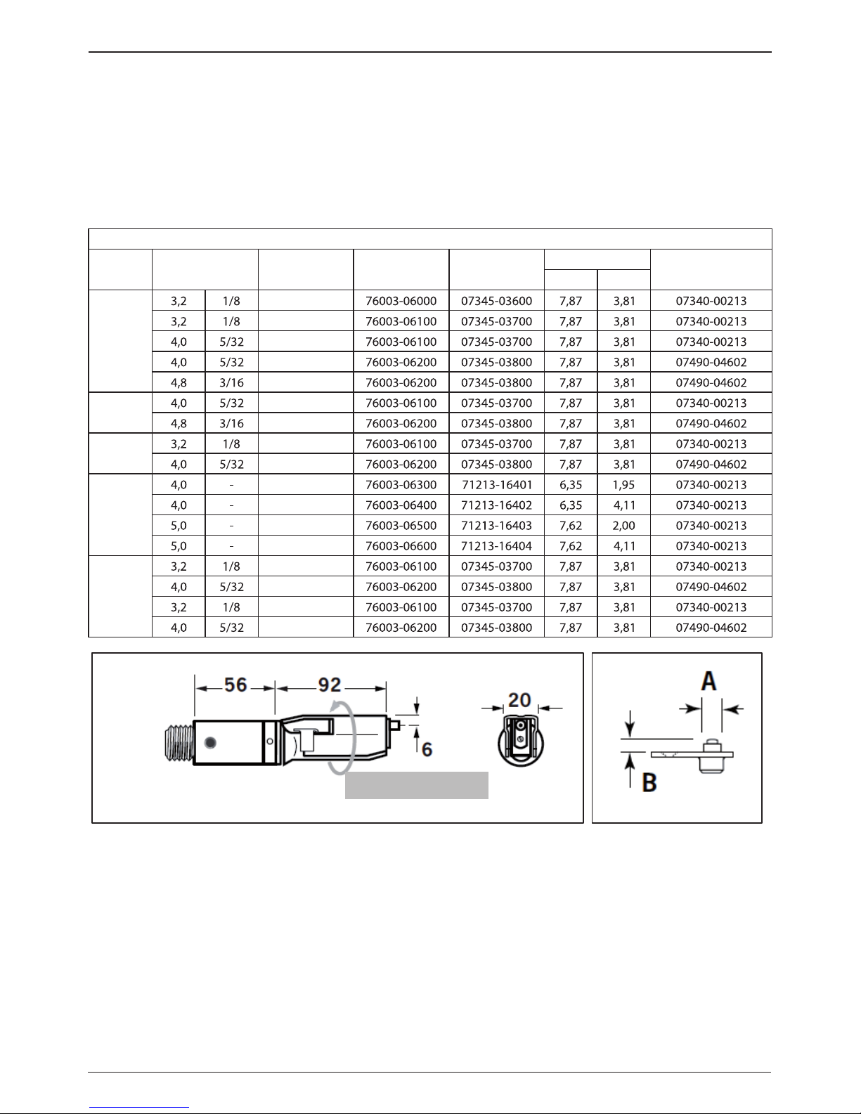
Table 1 - STRAIGHT SWIVEL HEAD Capability
RIVET
TYPE
RIVET
DIAMETER
RIVET
MATERIAL
SWIVEL
HEAD
NOSE
TIP
DIMENSIONS
JAWS
A B
AVEX
AL. ALLOY
STEEL
AL. ALLOY
STEEL
AL. ALLOY
BULBEX
AL. ALLOY
AL. ALLOY
AVINOX
ST. STEEL
ST. STEEL
AVSEAL II
AL. ALLOY
AL. ALLOY
AL. ALLOY
AL. ALLOY
STAVEX
STEEL
STEEL
ST. STEEL
ST. STEEL
360 rotation
Fig. 1 Fig. 2
Page 6
6
ENGLISH
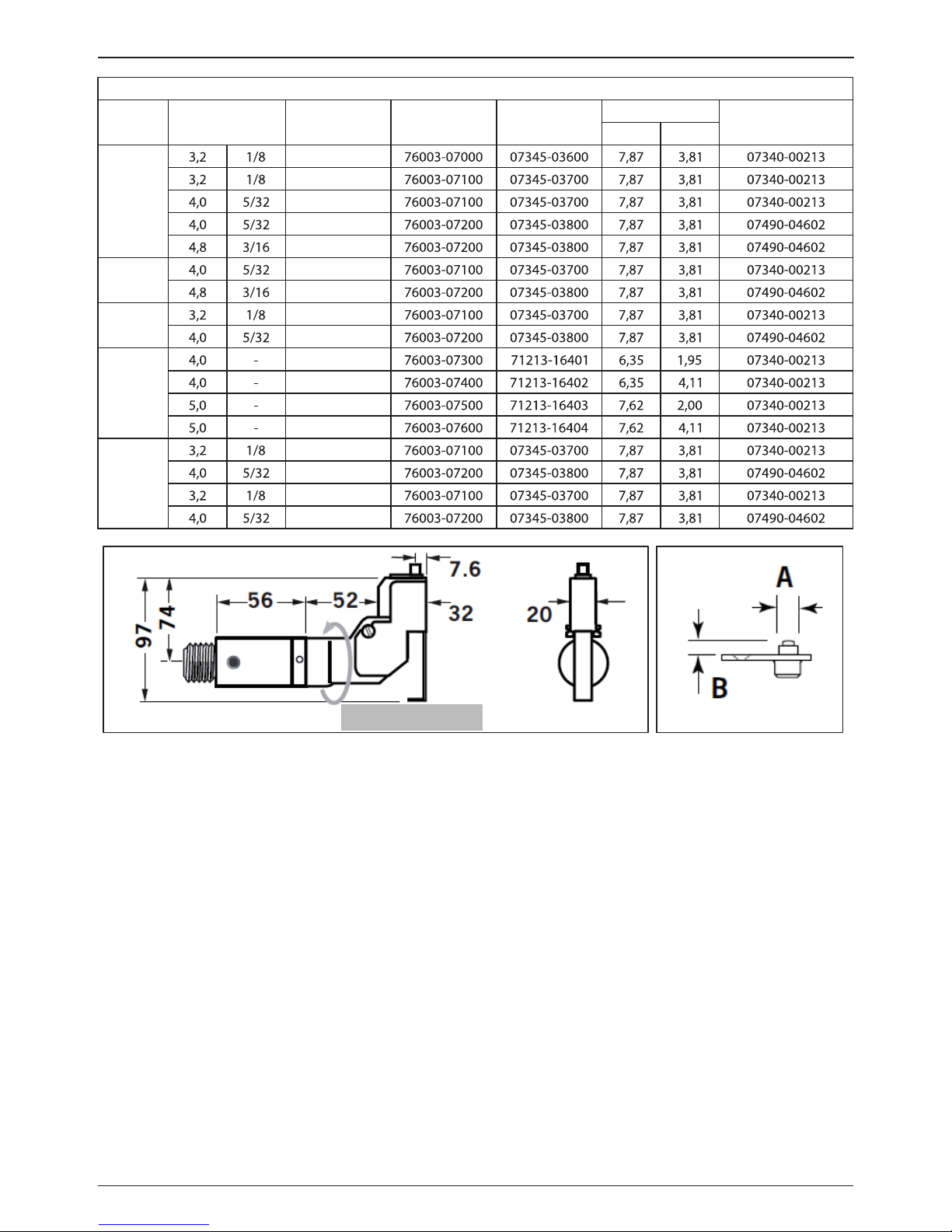
Table 2 - RIGHT-ANGLE SWIVEL HEAD Capability
RIVET
TYPE
RIVET DIAME-
TER
RIVET
MATERIAL
SWIVEL
HEAD
NOSE
TIP
DIMENSIONS
JAWS
A B
AVEX
AL. ALLOY
STEEL
AL. ALLOY
STEEL
AL. ALLOY
BULBEX
AL. ALLOY
AL. ALLOY
AVINOX
ST. STEEL
ST. STEEL
AVSEAL II
AL. ALLOY
AL. ALLOY
AL. ALLOY
AL. ALLOY
STAVEX
STEEL
STEEL
ST. STEEL
ST. STEEL
360 rotation
Fig. 3 Fig. 4
PREPARING THE BASE TOOL TO ACCEPT SWIVEL HEAD EQUIPMENT
IMPORTANT - READ THE SAFETY WARNINGS LISTED IN THE PROSET XT3 AND PROSET XT4 INSTRUCTION
MANUAL CAREFULLY BEFORE PUTTING INTO SERVICE.
IMPORTANT - THE AIR SUPPLY MUST BE TURNED OFF OR DISCONNECTED BEFORE FITTING OR
REMOVING THE SWIVEL HEAD NOSE ASSEMBLIES.
Refer to g. 5 and g. 6 and the table on page 10.
• The air supply must be disconnected.
• Rotate the Stem Collector (76003-05200) anti-clockwise and remove from the Collector Adapter (76003-
05104).
• Unscrew and remove the Deector Retaining Nut (76003-05102) together with the Stem Deector (76003-
05101).
• Place the Collector Adapter Cover (27) over the Collector Adapter (76003-05104) and then install Safety
Cap (26) until the end face of the Collector Adapter Cover (27) is secure against the mating face of the
Collector Adapter (76003-05104).
• If necessary, remove the complete Nose Assembly (76003-15000) as described on page 9 of the Proset
XT3 and Proset XT4 instruction manual.
Page 7
7
ENGLISH
• Remove Locknut (71210-02103) and Seal Housing (71210-02104).
• Attach the Stop Nut (25) onto the tool piston as far as it will go by hand.
• Fit the Jaw Spreader Housing (24) fully onto the tool piston and then tighten the Stop Nut (25) against the
Jae Spreader Housing (24).
• The tool is now ready to be tted with aswivel head.
Item numbers in bold refer to g. 7 and g. 8 and the table on page 10.
6
E
A
B
C
D
F
5
4
3
2
7
8
9
10
11
12
Fig. 5
Nose Assembly
76003-15000
Locknut
71210-02103
Collector Adapter
76003-05104
Stem Deector
76003-05101
Retaining Nut
76003-05102
Stem Collector
76003-05200
Seal Housing
71210-02104
6
E
A
B
C
D
F
5
4
3
7
8
9
10
11
12
Fig. 6
25
Stop Nut
27
Collector Adapter
Cover
26
Safety Cap
24
Jaw Spreader
Housing
Page 8
8
ENGLISH
SWIVEL HEAD FITTING INSTRUCTIONS
IMPORTANT - READ THE SAFETY WARNINGS LISTED IN THE PROSET XT3 AND PROSET XT4 INSTRUCTION
MANUAL CAREFULLY BEFORE PUTTING INTO SERVICE.
IMPORTANT - THE AIR SUPPLY MUST BE TURNED OFF OR DISCONNECTED BEFORE FITTING OR
REMOVING THE SWIVEL HEAD NOSE ASSEMBLIES.
The following procedure will allow you to assemble and t either of the swivel heads to the tool. If you order
acomplete swivel head rather than individual components, you will only need to start at step ‘L’.
All moving parts should be lubricated. Unless stated otherwise use Moly Lithium grease. Text highlighted in
grey tint refer only to the right-angle swivel head tting instructions.
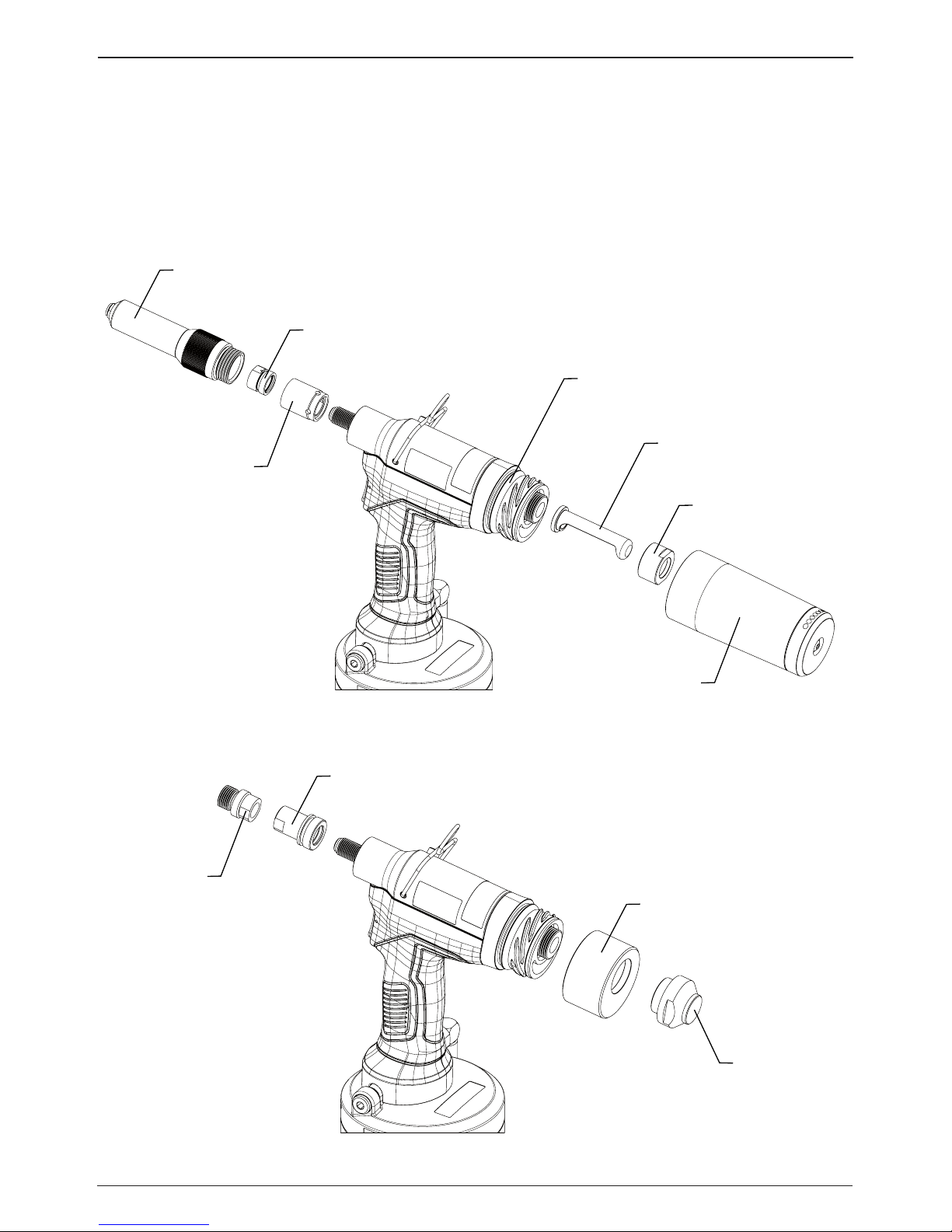
Item numbers in bold refer to the components in gures 7 and 8 and the table on page 10.
Note: Nose Tips (14) Jaws (17) vary to suit specic rivet. Refer to the table 1 and Table 2 to select the correct
nose tip for the rivet being installed.
STRAIGHT SWIVEL HEAD
Fig. 7
Page 9

9
ENGLISH
A. Fit Locking Ring 10 over Jaw Spreader Housing (24).
B. Coat Screw (13) with thread locking adhesive and use to secure Nose Tip (14) onto Body (5).
C. Lightly lubricate items (17), (18), (19), (20) and insert into Jaw Carrier (3) as shown. Secure with Screws (16).
D. Position Lever (4) into Body (5) and hold in place with pin (15) through the hole of Body (5) (not aslot).
E. Lubricate the sides of the Jaw Carrier Assembly and insert into Body (5).
F. Lubricate Rollers (8) and ENSURE that they will freely rotate in the holes of Adaptor (9). If necessary ream
the holes.
G. Position Spring Clip (7) over Adaptor (9) past the holes for the rollers and rotate until the locating peg is
aligned with the corresponding hole in Adaptor (9) (smallest hole).
H. Fit Adaptor (9) over the end of Body (5) and drop Rollers (8) into place. Push Spring Clip (7) over Rollers (8).
I. Insert Spindle (11) through Adaptor (9) into Jaw Carrier (3) until the hole lines up with slot in Body (5).
Temporarily hold in place with Pin (6).
J. Insert Pin (12) through the front slot of Body (5) into Jaw Carrier (3).
K. Hold the assembly vertical to prevent all pins dropping out and slide the jaw carrier assembly back and
forth afew times to ensure free movement. Go to M.
L. Remove Screws (23) (4 o) and Guard (1). On astraight swivel head also remove Screw (21) and Platform (22).
M. Push Pin(s) (6) out and let Spindle (11) drop out. Screw Spindle (11) onto the Jaw Spreader Housing (24),
leaving the small screw xing hole uppermost for straight swivel. Tighten gently with atommy bar.
N. Screw the assembly over Spindle (11) onto the tool. Replace Pin(s) (6).
O. On straight swivel heads attach Platform (22) onto the top of the Spindle (11) with Screw (21). Deburr the
back end of Platform (22) so that it cannot catch on Guard (1).
P. Snap Guard (1) over the assembly, align screw holes in guard with tapped holes in body assembly.
Q. Insert Pivot Pin (15) through slots in guard and hole in body. Fit Circlip (2) onto pivot pin so that the circlip
seats in groove provided.
R. Coat the thread of Screws (23) (4 o) with thread locking adhesive and screw into body assembly
securing guard to body assembly.
RIGHT-ANGLE SWIVEL HEAD
Fig. 8
Page 10

10
ENGLISH
Table 3 - PARTS LIST - STRAIGHT & RIGHT ANGLED SWIVEL HEAD
Item Description STRAIGHT SWIVEL RIGHT ANGLED SWIVEL
Guard
Circlip
Jaw Carrier
Lever
Body
Pivot Pin
Spring Clip
Roller
Adapter
Locking Ring
Spindle
Dowel Pin
Screw
Nose Tip See Table 1 See Table 2
Pivot Pin
Screw
Jaws
Jaw Spreader
Spring
Spring Guide
Screw
Platform
Screw
Jaw Spreader Housing
Stop Nut
Safety Cap
Collector Adapter Cover
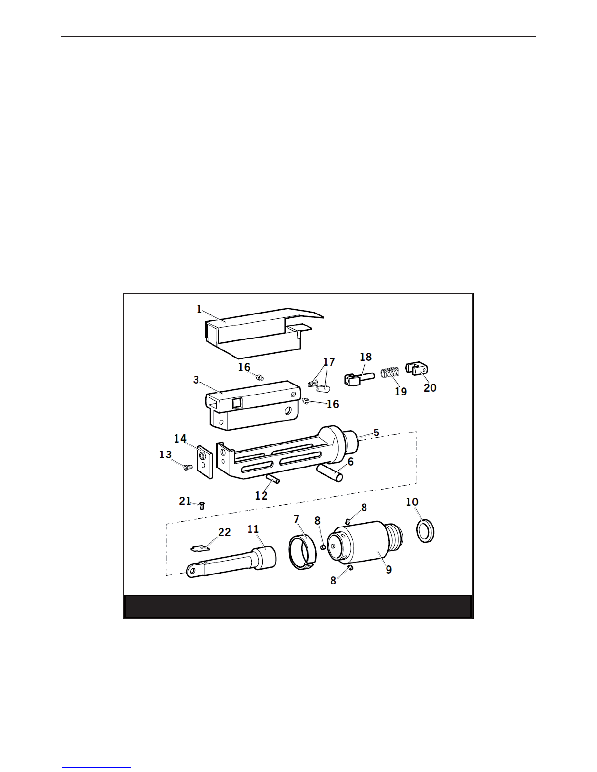
SWIVEL HEAD SERVICING INSTRUCTIONS
Swivel heads should be serviced at weekly intervals.
• Remove the complete head using the reverse procedure to the ‘Fitting instructions’ omitting step ‘L’.
• If Guard (1) is at all damaged it must be replaced by anew one.
• Any worn or damaged parts should be replaced.
• Pay particular attention to jaw carrier items in the upper illustration opposite as follows:
• Check wear on Jaws (17).
• Check that Jaw Spreader Tube (18) is not distorted.
• Check that Spring (19) is neither broken or distorted.
• Check that Spring Guide (20) is not damaged.
• Check that Spring clip (7) is not distorted. When removing Spring Clip (7), use two screwdrivers as shown
in the lower illustration opposite.
• Check for excessive wear on slots of Body (5).
• Assemble according to tting instructions.
Item numbers in bold refer to Swivel Head illustrations g. 9 and g. 10 on page 11. Guard (1) refers to g. 7
and g. 8 on page 8 and 9 and the table on page 10.
Page 11

11
ENGLISH
Fig. 9
Fig. 10
5. PIN TAIL DEFLECTOR KIT
The Pin Tail deector is avery simple alternative to the standard stem collector and allows access in restricted
areas. To replace the stem collector with the stem deector proceed as follows:
PREPARING THE BASE TOOL TO ACCEPT THE PIN TAIL DEFLECTOR KIT
IMPORTANT - READ THE SAFETY WARNINGS LISTED IN THE PROSET XT3 AND PROSET XT4 INSTRUCTION
MANUAL CAREFULLY BEFORE PUTTING INTO SERVICE.
IMPORTANT - THE AIR SUPPLY MUST BE TURNED OFF OR DISCONNECTED BEFORE FITTING OR
REMOVING THE PIN TAIL DEFLECTOR KIT.
Refer to g.11 and the table 4 on page 12. Refer also to the Proset XT3 and Proset XT4 Service Manuals 0790009410 and 07900-09411.
• Operate the tool so that the Piston (76003-02120 or 76004-02120) moves to the fully rear position.
• Continue to depress the trigger, then turn o the air supply to the tool using the On/O Valve (76003-
03700). The Piston Assembly will then stop in the fully rear position.
• The air supply must be disconnected.
• Rotate Stem Collector (76003-05200) anti-clockwise and remove from the Collector Adapter (76003-05104).
• Unscrew and remove the Deector Retaining Nut (76003-05102) and the Stem Deector (76003-05101).
• Remove the Collector Adapter (76003-05104), including ORing (07003-00530).
Page 12

12
ENGLISH
• Unscrew and remove the End Cap Assembly (76003-05110), including ORing (07003-00508). Observe
caution when removing the End Cap Assembly (76003-05110) as it will be subjected to acompressive
force from Spring (76003-02030).
• Remove Spring (76003-02030).
• If vacuum extraction is not required when using the Pin Tail Deector, unscrew and remove the Ejector
Nozzle (76003-05105 / 76004-05105) from the Piston (76003-02120 or 76003-02120).
6
E
A
B
C
D
F
5
4
3
2
7
8
9
10
11
12
Fig. 11
Collector Adapter
76003-05104
Stem Deector
76003-05101
Retaining Nut
76003-05102
Stem Collector
76003-05200
End Cap Assembly
76003-05110
Spring
76003-02030
Ejector Nozzle
76003-05105
76004-05105
FITTING THE PIN TAIL DEFLECTOR KIT
IMPORTANT - READ THE SAFETY WARNINGS LISTED IN THE PROSET XT3 AND PROSET XT4 INSTRUCTION
MANUAL CAREFULLY BEFORE PUTTING INTO SERVICE.
IMPORTANT - THE AIR SUPPLY MUST BE TURNED OFF OR DISCONNECTED BEFORE FITTING OR
REMOVING THE PIN TAIL DEFLECTOR KIT.
Refer to g. 12 and the table 4 on below. Refer also to the Proset XT3 and Proset XT4 Service Manuals 0790009410 and 07900-09411.
Item numbers in bold refer to g. 12 and table 4.
Table 4 - PARTS LIST - PIN TAIL DEFLECTOR KIT
Item Part Number Description Qty
1 76003-20101 Pin Tail Deector 1
2 76003-20102 Deector Retaining Nut 1
3 76003-20103 Collector Adapter Cover 1
4 76003-20104 Vacuum Shut-o Nozzle 1
5 07003-00511 ORing 1
Page 13

13
ENGLISH
• The air supply must be disconnected.
• If vacuum extraction is not required when using the Pin Tail Deector, attach the Vacuum Shut-o Nozzle
(4) to the Piston (76003-02120 or 76004-02120).
• Install the Spring (76003-02030).
• Attach the End Cap Assembly (76003-05110), including ORing (07003-00508).
• Assemble the Collector Adapter (76003-05104), including ORing (07003-00530).
• Place the Collector Adapter Cover (3) over the Collector Adapter (76003-05104).
• Insert the Pin Tail Deector (1) into the Deector Retaining Nut (2) so that the ange on the PinTail Deector (1) sits within the internal groove of the Deector Retaining Nut (2).
• Install Deector Retaining Nut (2), together with the Pin Tail Deector (1), on the End Cap Assembly
(76003-05110). Ensure the end face of the Collector Adapter Cover (3) is secure against the mating face of
the Collector Adapter (76003-05104).
6
E
A
B
C
D
F
5
4
3
7
8
9
10
11
12
Fig. 12
Collector Adapter
76003-05104
3
Collector Adapter
Cover
2
Deector Retaining
Nut
1
Pin Tail
Deector
End Cap Assembly
76003-05110
Spring
76003-02030
5
ORing
4
Vacuum Shut-o
Nozzle
Page 14

14
ENGLISH
6. Nose Extension Kits
Nose Extension Kits are supplied separately for tting to abase tool. Attached between the tool and the nose
assembly the extension allows access into deep channels. Refer to Table 5 below to select the correct Nose
Extension Kit for the Nose Assembly being used.
Table 5 - NOSE EXTENSION KITS - Compatability
Part Number Description
Compatible Nose Assemblies
Part Number Description
Nose Extension
Assembly
XT3 (Standard)
Standard Nose Assembly - Proset XT3 & XT4 Tools
Avdel Universal Nose Assembly - Proset XT3 & XT4 Tools
Avseal II Nose Assembly - Proset XT3 & XT4 Tools
Avseal II Nose Assembly - Proset XT3 & XT4 Tools
1/4“ Hemlok Nose Assembly - Proset XT3 & XT4 Tools
Avinox XT & Avibulb XT Nose Assembly - Proset XT3 &
XT4 Tools
Avseal II Nose Assembly - Proset XT3 & XT4 Tools
Nose Extension
Assembly
XT3 (nGenesis
Equipment)
Universal Nose Assembly for Genesis G2 tool
Extended Nose Assembly for Genesis G2 tool
Nose Assembly - 1/4“ Hemlok
Nose Assembly - 1/4“ Avibulb XT & 1/4“ Avinox XT
Standard Extension
for Maxlok
3/16“ Maxlok Nose Equipment
1/4“ Maxlok Nose Equipment
PREPARING THE BASE TOOL TO ACCEPT NOSE EXTENSION ASSEMBLY 76003-20200
IMPORTANT - READ THE SAFETY WARNINGS LISTED IN THE PROSET XT3 AND PROSET XT4 INSTRUCTION
MANUAL CAREFULLY BEFORE PUTTING INTO SERVICE.
IMPORTANT - THE AIR SUPPLY MUST BE TURNED OFF OR DISCONNECTED BEFORE FITTING OR
REMOVING THE NOSE EXTENSION KITS.
Refer to g. 13.
6
5
4
7
8
9
10
11
Fig. 13
Locknut
71210-02103
Pulling Head
76003-15002
& Jaw Guide
Assembly
Nose Casing
76003-15001
& Nose Tip
Pulling Head
Adapter
76003-15003
Page 15

15
ENGLISH
• The air supply must be disconnected.
• Unscrew the Nose Casing (76003-15001), including the Nose Piece, and ORing.
• Using spanners, separate and remove the Pulling Head (76003-15002) and Jaw Guide Assembly from the
Pulling Head Adapter (76003-15003).
• Using spanners, then unscrew the Pulling Head Adapter (76003-15003) from the tool piston.
FITTING THE NOSE EXTENSION ASSEMBLY 76003-20200
IMPORTANT - READ THE SAFETY WARNINGS LISTED IN THE PROSET XT3 AND PROSET XT4 INSTRUCTION
MANUAL CAREFULLY BEFORE PUTTING INTO SERVICE.
IMPORTANT - THE AIR SUPPLY MUST BE TURNED OFF OR DISCONNECTED BEFORE FITTING OR
REMOVING THE NOSE EXTENSION KITS.
Refer to g. 14 and Table 6.
Table 6 - PARTS LIST - NOSE EXTENSION ASSEMBLY
76003-20200
Item Part Number Description Qty
Nose Casing Extension - XT3
Pulling Head Extension
ORing
6
5
7
8
9
10
11
Fig. 14
Locknut
71210-02103
2
Pulling Head
Extension
3
ORing
1
Nose Casing
Extension
Nose Casing
76003-15001
& Nose Tip
Pulling Head
76003-15002
& Jaw Guide
Assembly
Pulling Head
Adapter
76003-15003
• The air supply must be disconnected.
• Install the Pulling Head Adapter (76003-15003) fully onto the tool piston and then tighten the locknut
(71210-02103) against it.
Page 16

16
ENGLISH
• Apply Loctite 243 to the mating threads of the Pulling Head Adapter (76003-15003) and the Pulling Head
Extension (2).
• Attach the Pulling Head Extension (2) to the Pulling Head Adapter (76003-15003) and tighten with spanners.
• Apply Loctite 243 to the mating threads of the Pulling Head Extension (2) and the Pulling Head (76003-
15002).
• Attach the Pulling Head (76003-15002) and Jaw Guide Assembly to the Pulling Head Extension (2) and
tighten with spanners.
• Place ORing (3) over the threads on the Nose Casing Extension (1).
• Place Nose Casing Extension (1) over the Pulling Head (76003-15002), Jaw Guide Assembly and Pulling
Head Extension (2) and tighten fully onto the tool.
• Place Nose Casing (76003-15001) and Nose Tip over the jaw guide and tighten fully onto the Nose Casing
Extension (1).
PREPARING THE BASE TOOL TO ACCEPT NOSE EXTENSION ASSEMBLY 76003-20300 & 71230-20300
IMPORTANT - READ THE SAFETY WARNINGS LISTED IN THE PROSET XT3 AND PROSET XT4 INSTRUCTION
MANUAL CAREFULLY BEFORE PUTTING INTO SERVICE.
IMPORTANT - THE AIR SUPPLY MUST BE TURNED OFF OR DISCONNECTED BEFORE FITTING OR
REMOVING THE SWIVEL HEAD NOSE ASSEMBLIES.
• The air supply must be disconnected.
• Remove the complete Nose Assembly (76003-15000) as described on page 9 of the Proset XT3 and Proset
XT4 instruction manual.
FITTING THE NOSE EXTENSION ASSEMBLY 76003-20300 & 71230-20300
IMPORTANT - READ THE SAFETY WARNINGS LISTED IN THE PROSET XT3 AND PROSET XT4 INSTRUCTION
MANUAL CAREFULLY BEFORE PUTTING INTO SERVICE.
IMPORTANT - THE AIR SUPPLY MUST BE TURNED OFF OR DISCONNECTED BEFORE FITTING OR
REMOVING THE NOSE EXTENSION KITS.
Refer to g. 15 and Tables 7 and 8.
Page 17

17
ENGLISH
3
5
4
6
7
8
3
5
4
6
7
8
5
ORing
1
Jaw Housing
Extension
4
Jaw
Spreader
Housing
6
Locking Ring
3
ORing
2
Nose Casing
Extension
Fig. 15
Table 7 - PARTS LIST - NOSE EXTENSION ASSEMBLY
76003-20300
Table 8 - PARTS LIST - NOSE EXTENSION ASSEMBLY
71230-20300
Item Part Number Description Qty Item Part Number Description Qty
Jaw Housing Extension Jaw Housing Extension
Nose Casing Extension
- XT3
Nose Casing Extension
ORing
Jaw Spreader Housing
ORing
Locking Ring
To t Nose Extension Assembly 76003-20300
• Remove any nose assembly components.
• Install the Jaw Spreader Housing (4) and Oring (5) fully onto the tool piston and then tighten the locknut
(71210-02103) against it.
• Fit the Locking Ring (6) over the Jaw Spreader Housing (4) thread.
• Attach the Jaw Housing Extension (1) to the Jaw Spreader Housing (4) and tighten with spanners.
• Place Nose Casing Extension (2) over the Jaw Housing Extension (1) and tighten fully onto the tool.
• Fit the nose assembly onto the Jaw Housing Extension (1) and Nose Casing Extension (2).
To t Nose Extension Assembly 71230-20300
• Remove any nose assembly components.
• Attach the Jaw Housing Extension (1) to the Jaw Spreader Housing (4) and tighten with spanners.
• Place Nose Casing Extension (2) over the Jaw Housing Extension (1) and tighten fully onto the tool.
• Fit the nose assembly onto the Jaw Housing Extension (1) and Nose Casing Extension (2).
Page 18

18
ENGLISH
7. FIXED COLLECTOR BOTTLE KIT
The Fixed Collector Bottle an alternative to the standard stem collector and allows greater storage capacity for
collection of large rivet stems. To replace the stem collector with the Fixed Collector proceed as follows:
PREPARING THE BASE TOOL TO ACCEPT THE FIXED COLLECTOR BOTTLE KIT
IMPORTANT - READ THE SAFETY WARNINGS LISTED IN THE PROSET XT3 AND PROSET XT4 INSTRUCTION
MANUAL CAREFULLY BEFORE PUTTING INTO SERVICE.
IMPORTANT - THE AIR SUPPLY MUST BE TURNED OFF OR DISCONNECTED BEFORE FITTING OR
REMOVING THE FIXED COLLECTOR BOTTLE KIT.
Refer to g.16 below. Refer also to the Proset XT3 and Proset XT4 Service Manuals 07900-09410 and 07900-
09411.
6
E
A
B
C
D
F
5
4
3
7
8
9
10
11
12
Collector Adapter
76003-05104
Fig. 16 Stem Deector
76003-05101
Retaining Nut
76003-05102
Stem Collector
76003-05200
End Cap Assembly
76003-05110
Spring
76003-02030
MCS Valve Assembly
76003-05300
Spring
76003-05304
• The air supply must be disconnected.
• Rotate Stem Collector (76003-05200) anti-clockwise and remove from the Collector Adapter (76003-
05104).
• Unscrew and remove the Deector Retaining Nut (76003-05102) and the Stem Deector (76003-05101).
• Remove the Collector Adapter (76003-05104), including ORing (07003-00530).
• Unscrew and remove the End Cap Assembly (76003-05110), including ORing (07003-00508). Observe
caution when removing the End Cap Assembly (76003-05110) as it will be subjected to acompressive
force from Spring (76003-02030).
• Remove Spring (76003-02030).
• Remove the MCS Valve Assembly (76003-05300) and the Spring (76003-05304) from the Tool.
Page 19

19
ENGLISH
FITTING THE FIXED COLLECTOR BOTTLE KIT
IMPORTANT - READ THE SAFETY WARNINGS LISTED IN THE PROSET XT3 AND PROSET XT4 INSTRUCTION
MANUAL CAREFULLY BEFORE PUTTING INTO SERVICE.
IMPORTANT - THE AIR SUPPLY MUST BE TURNED OFF OR DISCONNECTED BEFORE FITTING OR
REMOVING THE FIXED COLLECTOR BOTTLE KIT.
Refer to g. 16 and 17 and the table 9 below. Refer also to the Proset XT3 and Proset XT4 Service Manuals
07900-09410 and 07900-09411.
Table 9 - PARTS LIST - FIXED COLLECTOR BOTTLE KIT
76003-20500
Item Part Number Description Qty
XT3 Fixed Bottle Assembly
Fixed Bottle Adapter Assembly
Fixed Bottle End Cap Assembly
Retaining Nut
Seal
ORing
Sealing Plug
ORing
3
2
5
C
4
6
7
8
A
B
3
2
5
C
4
6
7
8
A
B
Fig. 17
1
XT3 Fixed Bottle
Assembly
2
Fixed Bottle Adapter
Assembly
3
Fixed Bottle
End Cap Assembly
6
ORing
5
Seal
7
Sealing Plug
8
ORing
4
Retaining Nut
Item numbers in bold refer to g. 17 and table 9.
• The air supply must be disconnected.
• Install the Spring (76003-02030) into the recess in the Fixed Bottle End Cap Assembly (3).
• Attach Fixed Bottle End Cap Assembly (3), together with the Seal (5), ORing (6) and Spring (76003-02030)
to the tool head assembly and tighten with aspanner.
• Insert the Sealing Plug (7), together with ORing (8) fully into the bore in the tool head assembly.
• Assemble the Fixed Bottle Adapter Assembly (2) over the Fixed Bottle End Cap Assembly (3) and on to the
tool.
Page 20

20
ENGLISH
• Fit the Fixed Bottle Assembly (1) over the locating pins in Fixed Bottle Adaptor Assembly (2).
• Rotate the Fixed Bottle Assembly (1) outer so that the aperture in the Fixed Bottle Assembly (1) inner is
fully exposed.
• Screw on the Retaining Nut (4) and tighten using atommy bar.
8. MCS5000 ADAPTER KITS
The MCS5000 Adapter Kits enable the tool to be connected the MCS5000 remote vacuum rivet stem collector.
To replace the stem collector with the MCS5000 Adapter Kit proceed as follows:
PREPARING THE BASE TOOL TO ACCEPT THE MCS5000 ADAPTER KITS
IMPORTANT - READ THE SAFETY WARNINGS LISTED IN THE PROSET XT3 AND PROSET XT4 INSTRUCTION
MANUAL CAREFULLY BEFORE PUTTING INTO SERVICE.
IMPORTANT - THE AIR SUPPLY MUST BE TURNED OFF OR DISCONNECTED BEFORE FITTING OR
REMOVING THE MCS5000 ADAPTER KITS.
Refer to g.18 below. Refer also to the Proset XT3 and Proset XT4 Service Manuals 07900-09410 and 07900-
09411.
• Operate the tool so that the Piston (76003-02120 or 76004-02120) moves to the fully rear position.
• Continue to depress the trigger, then turn o the air supply to the tool using the On/O Valve (76003-
03700). The Piston Assembly will then stop in the fully rear position.
• The air supply must be disconnected.
• Rotate Stem Collector (76003-05200) anti-clockwise and remove from the Collector Adapter (76003-
05104).
• Unscrew and remove the Deector Retaining Nut (76003-05102) and the Stem Deector (76003-05101).
• Remove the Collector Adapter (76003-05104), including ORing (07003-00530).
• Unscrew and remove the End Cap Assembly (76003-05110), including ORing (07003-00508). Observe
caution when removing the End Cap Assembly (76003-05110) as it will be subjected to acompressive
force from Spring (76003-02030).
• Remove Spring (76003-02030).
• If vacuum extraction is not required when using the Pin Tail Deector, unscrew and remove the Ejector
Nozzle (76003-05105 / 76004-05105) from the Piston (76003-02120 or 76003-02120).
Page 21

21
ENGLISH
6
E
A
B
C
D
F
5
4
3
2
7
8
9
10
11
12
Fig. 18
Collector Adapter
76003-05104
Stem Deector
76003-05101
Retaining Nut
76003-05102
Stem Collector
76003-05200
End Cap Assembly
76003-05110
Spring
76003-02030
Ejector Nozzle
76003-05105
76004-05105
FITTING THE MCS5000 ADAPTER KITS
IMPORTANT - READ THE SAFETY WARNINGS LISTED IN THE PROSET XT3 AND PROSET XT4 INSTRUCTION
MANUAL CAREFULLY BEFORE PUTTING INTO SERVICE.
IMPORTANT - THE AIR SUPPLY MUST BE TURNED OFF OR DISCONNECTED BEFORE FITTING OR
REMOVING THE MCS5000 ADAPTER KITS.
Refer to g. 19 and the table 10 below.
Table 10 - PARTS LIST - MCS5000 ADAPTER KITS
Item Description
76003-20600 76003-20700
3.2MM (1/8“) TO 4.8MM
(3/16“) RIVETS
6.4MM (1/4“) RIVETS
Strain Relief
MCS Hose
SMC Fitting (1/8“ Rivets)
SMC Fitting (5/32“ & 3/16“ Rivets)
SMC Fitting (1/4“ Rivets)
Adapter Bushing (1/8“ Rivets)
Adapter Bushing (5/32“ & 3/16“ Rivets)
Adapter Bushing (1/4“ Rivets)
MCS Adapter
ORing
Collector Adapter Cover
Vacuum Shut-o Nozzle
ORing
Page 22

22
ENGLISH
6
E
A
B
C
D
F
5
4
3
2
7
8
9
10
11
12
Fig. 19
Collector Adapter
76003-05104
11
Collector Adapter
Cover
10
ORing
9
MCS
Adapter
6, 7, 8
Adapter Bushing
3, 4, 5
SMC Fitting
2
MCS Hose
1
Strain Relief
End Cap Assembly
76003-05110
Spring
76003-02030
13
ORing
12
Vacuum Shut-o
Nozzle
Item numbers in bold refer to g. 19 and table 10.
• The air supply must be disconnected.
• Attach the Vacuum Shut-o Nozzle (12) to the Piston (76003-02120 or 76004-02120).
• Install the Spring (76003-02030).
• Attach the End Cap Assembly (76003-05110), including ORing (07003-00508).
• Assemble the Collector Adapter (76003-05104), including ORing (07003-00530).
• Place the Collector Adapter Cover (11) over the Collector Adapter (76003-05104).
• Insert ORing (10) into the recess with the MCS Adapter (9)
• Install MCS Adapter (9) on the End Cap Assembly (76003-05110) using aspanner. Ensure the end face of
the Collector Adapter Cover (11) is secure against the mating face of the Collector Adapter (76003-05104).
• Insert the Adapter Bushing (6, 7, or 8) into the MCS Adapter (9) ensuring the correct size for the rivet to
be placed and the correct orientation. The larger internal bore opening in the Adapter Bushing (6, 7, or 8)
should face towards the MCS Adapter (9).
• Insert the SMC tting (3, 4 of 5) into the MCS Adapter (9), ensuring the correct size for the rivet to be
placed.
• For 3.2mm (1/8”), 4.0mm (5/32”) and 4.8mm (3/16”) rivets insert the Strain Relief (1) over the SMC Fitting
(3 or 4) and fully on to the MCS Adapter (9).
• For 6.4mm (1/4”) rivets insert the MCS Hose (2) into the SMC Fitting (5).
• Connect the Tool and MCS5000 kit to the MCS5000 unit as instructed within the MCS5000 datasheet.
Page 23

23
ENGLISH
Page 24

For an authorized distributor nearby please check
www.StanleyEngineeredFastening.com/econtact/distributors
Manual Number Issue C/N
07900-09415 A 17/143
STANLEY Engineered Fastening
Avdel UK Limited
Stanley House, Works Road
Letchworth Garden City, Hertfordshire SG6 1JY
Tel. +44 1582 900-000 . Fax -001
Enquiries2@sbdinc.com
© 2017 Stanley Black & Decker, Inc.
Avdel®, NeoBolt® , Avseal®, Avdelok®, Monobolt®, AvBolt® and Avtainer® are registered trademarks of Avdel
UK Limited. AV™ is atrademark of Avdel UK Limited. The names and logos of other companies mentioned
herein may be trademarks of their respective owners. This document is for informational purposes only.
Avdel UK Limited makes no warranties, expressed or implied, in this document.
Data shown is subject to change without prior notice as aresult of continuous product development and
improvement policy. Your local STANLEY Engineered Fastening representative is at your disposal should
you need to conrm latest information.
 Loading...