

Page 1

ProSertTM XTN20 Blind Rivet Nut Tool – 74202
Hydro-Pneumatic Power Tool
Instruction Manual
Hydro-Pneumatic Blind Rivet Nut Tool
Rebitadeira Hidropneumática de Porca Rebite Cega
Remachadora hidroneumática para tuercas remachables
Sertisseuse Oléopneumatique pour écrous aveugles
EN
BR
ES
FR
Page 2
2
2
3
4
5
6
1
7
8
9
15
14
11 12 13
Fig. 2
Fig. 1
13
12
14
15
16
2
3
6
1
7
11
1
2
3
4
10
11
19
21
17
18
20
4
5
9
8
18 19
1918
Page 3
3
Fig. 3
Page 4

4
Page 5

CONTENT
PA GE
1. Safety Denitions 6
2. Specication 8
2.1 Placing Tool Specication 8
2.2 The Package Contains 8
2.3 Main Components List 9
3. Tool Setup 10
4. Operating Instructions 10
4.1 Nose Equipment 10
4.2 Air Supply 11
4.3 Setting Instructions 11
5. Operating Procedure 12
6. Servicing the Tool 13
6.1 Daily Servicing 13
6.2 Weekly Servicing 13
7. Declaration of Conformity 14
8. Protect your investment . Warranty registration 15
© 2015 Stanley Black & Decker, Inc.
All rights reserved.
The information provided may not be reproduced and/or made public in any way and through any means
(electronically or mechanically) without prior explicit and written permission from STANLEY Engineered
Fastening. The information provided is based on the data known at the moment of the introduction of this
product. STANLEY Engineered Fastening pursues a policy of continuous product improvement and therefore
the products may be subject to change. The information provided is applicable to the product as delivered
by STANLEY Engineered Fastening. Therefore, STANLEY Engineered Fastening cannot be held liable for any
damage resulting from deviations from the original speci cations of the product.
The information available has been composed with the utmost care. However, STANLEY Engineered Fastening
will not accept any liability with respect to any faults in the information nor for the consequences thereof.
STANLEY Engineered Fastening will not accept any liability for damage resulting from activities carried out
by third parties. The working names, trade names, registered trademarks, etc. used by STANLEY Engineered
Fastening should not be considered as being free, pursuant to the legislation with respect to the protection of
trade marks.
Original Instruction
5
ENGLISH
Page 6
This instruction manual must be read by any person installing or operating this tool with particular attention
to the following safety rules.
1. Safety De nitions
The de nitions below describe the level of severity for each signal word. Please read the manual and pay
attention to these symbols.
DANGER: Indicates an imminently hazardous situation which, if not avoided, will result in death or serious
injury.
v WARNING: Indicates a potentially hazardous situation which, if not avoided, could result in death
or serious injury.
CAUTION: Indicates a potentially hazardous situation which, if not avoided, may result in minor or moderate
injury.
CAUTION: Used without the safety alert symbol indicates a potentially hazardous situation which, if not
avoided, may result in property damage.
Improper operation or maintenance of this product could result in serious injury and property damage.
Read and understand all warnings and operating instructions before using this equipment. When using
power tools, basic safety precautions must always be followed to reduce the risk of personal injury.
SAVE THESE INSTRUCTIONS.
WARNING:
1. Do not use outside the design intent of Placing STANLEY Engineered Fastening Blind Rivet Nuts.
2. Use only parts, fasteners, and accessories recommended by the manufacturer.
3. Do not modify the tool in any way. Any modi cation to the tool is undertaken by the customer and will be the
customer’s entire responsibility and void any applicable warranties.
4. Prior to use, check for misalignment or binding of moving parts, breakage of parts, and any other condition
that a ects the tool’s operation. If damaged, have the tool serviced before using. Remove any adjusting key
or wrench before use.
5. The tool must be maintained in a safe working condition at all times and examined at regular intervals for
damage and function by trained personnel. Any dismantling procedure will be undertaken only by trained
personnel. Do not dismantle this tool without prior reference to the maintenance instructions.
6. The operating supply air must not exceed 7 bar (100 PSI).
7. Operators and others in work area must wear ANSI Z87.1 CAN/CSA Z94.3 approved safety glasses with side
shields. Always wear safety glasses and ear protection during operation.
8. Dress properly. Do not wear loose clothing or jewellery. Keep your hair, clothing and gloves away from moving
parts. Loose clothes, jewellery or long hair can be caught in moving parts.
9. Do not operate a tool that is directed towards any person(s).
6
ENGLISH
Page 7

10. DO NOT operate tool with the nose housing removed.
11. Adopt a rm footing or a stable position before operating the tool.
12. Prior to use, inspect airlines for damage, all connections must be secure. Do not drop heavy objects on hoses.
A sharp impact may cause internal damage and lead to premature hose failure.
13. Do not lift the placing tool by the hose. Always use the placing tool handle.
14. Vent holes must not become blocked or covered.
15. Disconnect the air hose from the tool before performing any maintenance, attempting to adjust, t
or remove a nose assembly.
16. Keep tool handles dry, clean, and free from oil and grease.
17. When carrying the tool from place to place keep hands away from the trigger to avoid inadvertent activation.
18. Never leave operating tool unattended. Disconnect air hose when tool is not in use.
19. Adequate clearance is required for the tool operators hands before proceeding.
20. Do not abuse the tool by dropping or using it as a hammer.
21. Keep dirt and foreign matter out of the hydraulic system of the tool as this will cause the tool to malfunction.
STANLEY Engineered Fastening policy
is one of continuous product development and improvement
and we reserve the right to change the speci cation
of any product without prior notice.
7
ENGLISH
Page 8

Items with a * may require a mandrel adaptor kit (74202-02200 found in the Accessories Manual 07900-01073). A complete ProSert
XTN20 (74202) tool is made up of the base tool (part number 74202-02000) and the appropriate nose assembly for the insert.
2. Speci cation
UNDER NO CIRCUMSTANCES SHOULD ANY MAINTENANCE OR SERVICING BE CONDUCTED APART FROM
NOSE EQUIPMENT CHANGE.
The ProSert XTN20 hydro-pneumatic tool is designed for placing STANLEY Engineered Fastening Blind Rivet
Nuts through adjustment of the force and/or the stroke.
The ProSert XTN20 Tool is used to place Blind Rivet Nuts from a range of M3 to M10 when coupled with the relevant
nose equipment. Imperial nose equipment is also available to place UNC and UNF inch thread size Blind Rivet Nuts.
The safety instructions must be followed at all times.
2.1. Placing Tool Speci cation
2.2. The package contains:
• 1 XTN20 Blind Rivet Nut Tool
• 1 set M4, M5, M6, M8 Nose Equipment & Mandrels
• 1 Printed Instruction Manual
• 1 Maintenance Kit
Pull Force: Pull @ stated pull pressure 5.0 bar 17.65 kN 3968 lbf
Air Supply Pressure: Min/Max 5-7 bar 72.5-101.5 lbf/in
2
Oil Pressure: Pull (max) 230 bar 3336 lbf/in
2
Stroke: Piston stroke 3-7 mm 0.118-0.275 in
Weight: Including nose equipment 1.59 kg 3.50 lb
Noise Level: Uncertainty noise: K=3dB(A) <75 dB(A) <75 dB(A)
Vibration: Uncertainty vibration: K=0.1 m/s² <2.5 m/s
2
<8 ft/s
2
Motor Speed: Forward & Reverse 2000rpm 2000rpm
Additional Features:
Pull-to-Force operating mode Yes
Pull-to-Stroke operating mode Yes
Auto Spin On/Spin O Yes
Tool Free Mandrel ttings Yes
Manual Reverse override Yes
Hydraulic Lip Seals & O-rings Yes
Material: - Aluminium Steel Stainless Steel
Avdel® Product
Range:
Eurosert® - M3-M10 M4-M5
Thin Sheet Nutsert® M3-M10 M3-M10 M3-M10
DK/DL M4-M10 Euro Hexsert®/Hexsert® - M3-M8 M6
High Strength Hexsert® - M6-M8 Squaresert® - M5-M8 -
POP Nut®
Product Range:
Standard Nut* M3-M10 M3-M8 M4-M6
Knurled Nut* M4-M8 M4-M6 Closed End Nut* M3-M10 M3-M8 M4-M6
Hexagonal Nut* M4-M8 M4-M8 M4-M6
Tetra Nut* M4-M8 M4-M8 HB Bolt* M6-M8 M6-M8 Pipe Nut* M6 M6 -
8
ENGLISH
Page 9

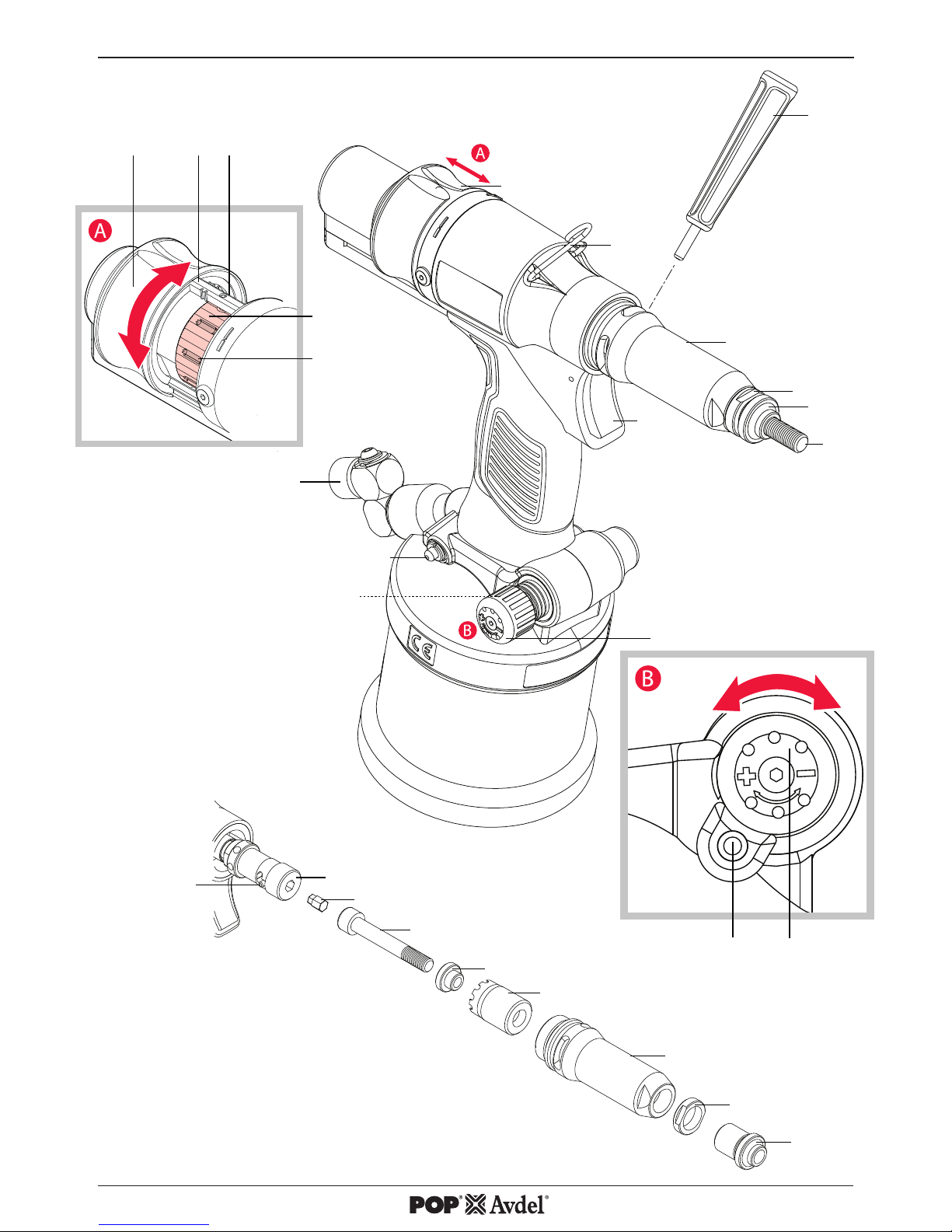
2.3. Main components list
ref g. 1 & 2 Re-order
Spare part numbers Qty
1 Mandrel
M4 07555-09004 1
M5 07555-09005 1
M6 07555-09006 1
M8 07555-09008 1
2 Nose Tip
M4 07555-00904 1
M5 07555-00905 1
M6 07555-00906 1
M8 07555-00908 1
3 Lock Nut - 07555-00901 1
4 Nose Casing - 74202-02021 1
5 Chuck Nut - 74202-02022 1
6 Reducing Sleeve
M4 07555-09104 1
M5 07555-09105 1
M6 07555-09106 1
M8 07555-09108 1
7 Drive Shaft
M4 07555-01004 1
M5 07555-01005 1
M6 07555-01006 1
M8 07555-01008 1
8 Mandrel Adaptor - 74202-02023 1
9 Nose Rod - 74202-02039 10 Suspension Ring - 74202-02012 1
11 Stroke Slider - 74202-02092 1
12 Stroke Indication Markings - - 13 Stroke Locking Pin - 74202-02095 1
14 Stroke Setter - 74202-02010 1
15 Stroke Setter Recess - - 16 Air Inlet Assembly - 74202-02103 1
17 Manual Reverse Trigger - 74202-02030 1
18 Regulator Lock - 74202-02038 1
19 Pressure Regulator - 74202-02037 1
20 Trigger - 74202-02020 1
21 Pin Punch - 07900-00624 1
Complete nose assembly
M4 07555-09884
M5 07555-09885
M6 07555-09886
M8 07555-09888
* All sizes are supplied with Lock Nut (3) 07555-00901.
For additional sizes please visit www.StanleyEngineeredFastening.com
9
ENGLISH
Page 10

3. Tool Setup
IMPORTANT - READ THE SAFETY RULES ON PAGE 6 & 7 CAREFULLY BEFORE PUTTING INTO SERVICE.
Before Use
• Select relevant size nose equipment and install.
• Connect the placing tool to the air supply. Test pull and return cycles by depressing and releasing the
trigger 20.
• Set the tool for desired stroke/pressure.
CAUTION - correct supply pressure is important for proper function of the installation tool. Personal injury or
damage to equipment may occur without correct pressures. The supply pressure must not exceed that listed in the
placing tool speci cation.
4. Operating Instructions
IMPORTANT - READ THE SAFETY RULES ON PAGE 6 & 7 CAREFULLY BEFORE PUTTING INTO SERVICE.
IMPORTANT - THE AIR SUPPLY MUST BE TURNED OFF OR DISCONNECTED BEFORE FITTING OR
REMOVING THE NOSE ASSEMBLY.
4.1 Nose Equipment (see Fig.2).
Fitting Instructions
Item numbers in bold refer to nose assembly components in g 1.
• Air supply must be disconnected.
• If still tted, remove the Nose Casing 4 and the Chuck Nut 5,while pulling back the spring loaded Nose
Rod 9. •
• Insert Drive Shaft 7 into Mandrel Adaptor 8.
• Fit Mandrel 1 onto Drive Shaft 7.
• Insert Reducing Sleeve 6 (if speci ed) into the Chuck Nut 5.
• Screw the Chuck Nut 5 onto the Mandrel Adaptor 8 while pulling back the spring loaded Nose Rod 9.
Tighten the Chuck Nut 5 clockwise.
• While holding the Tool, screw on the Nose Casing 4 and Nose Tip 2 with the nose tip Lock Nut 3.
• The reverse operation is carried out for equipment removal.
With the tool still disconnected from the air supply, screw a Blind Rivet Nut onto the Mandrel manually.
• Position Nose Tip 2 on the Nose Casing 4 and lock it with Lock Nut 3 so that the Mandrel 1 protrudes
slightly beyond the insert.
• Lock the Lock Nut 3 by turning clockwise with a spanner*. Remove the Blind Rivet Nut from
Mandrel.
*Refer to items included in the Maintenance Kit 07900-09301 page 13.
10
ENGLISH
Page 11
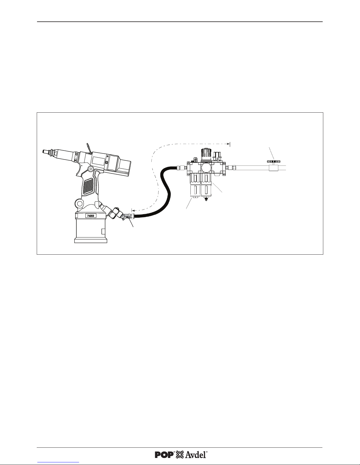
4.2 Air Supply
• All tools are operated with compressed air at an minimum pressure of 5.0 bar.
• Pressure regulators and automatic oiling/ ltering systems to be used on the main air supply within 3
metres of the tool (see g. 4).
• Air supply hoses will have a minimum working e ective pressure rating of 150% of the maximum pressure
produced in the system or 10 bar, whichever is the highest.
• Air hoses must be oil resistant, have an abrasion resistant exterior and be armoured where operating
conditions may result in hoses being damaged.
• All air hoses MUST have a minimum bore diameter of 6.4 millimetres.
LUBRICATOR
PRESSURE REGULATOR AND
FILTER DRAIN DAILY
STOP COCK
USED DURING MAINTENANCE
OF FILTER/REGULATOR OR
LUBRICATION UNITS
MAIN SUPPLY
3 METRES MAXIMUM
If above system is not available you can use the following alternative:
• Before use or when rst putting the tool into service, pour a few drops of clean, light lubricating oil into
the air inlet of the tool if no lubricator is tted on air supply. If the tool is in continuous use, the air hose
should be disconnected from the main air supply and the tool lubricated every two to three hours.
• Check for air leaks. If damaged, hoses and couplings must be replaced by new items.
• If there is no lter on the pressure regulator, bleed the air line to clear it of accumulated dirt or water
before connecting air hose to the tool.
4.3 Setting Instructions
• The stroke adjustment feature is mainly used for smaller insert sizes M3-M4.
• If you are setting the tool for optimum stroke the Stroke Setter should be wound in to minimum stroke
(3mm) and the Pressure Regulator 19 be wound in to maximum setting.
• If you are setting the tool for optimum pressure the Stroke Setter should be wound out to maximum
stroke (7mm) and the Pressure Regulator 19 be wound out to minimum setting.
When dealing with di erent grip thicknesses, it is always recommended that the tool is set for optimum
pressure rather than optimum stroke. Use the maximum grip condition to set optimum pressure.
Fig. 4
1/4" GAS
CONNECTION
11
ENGLISH
Page 12

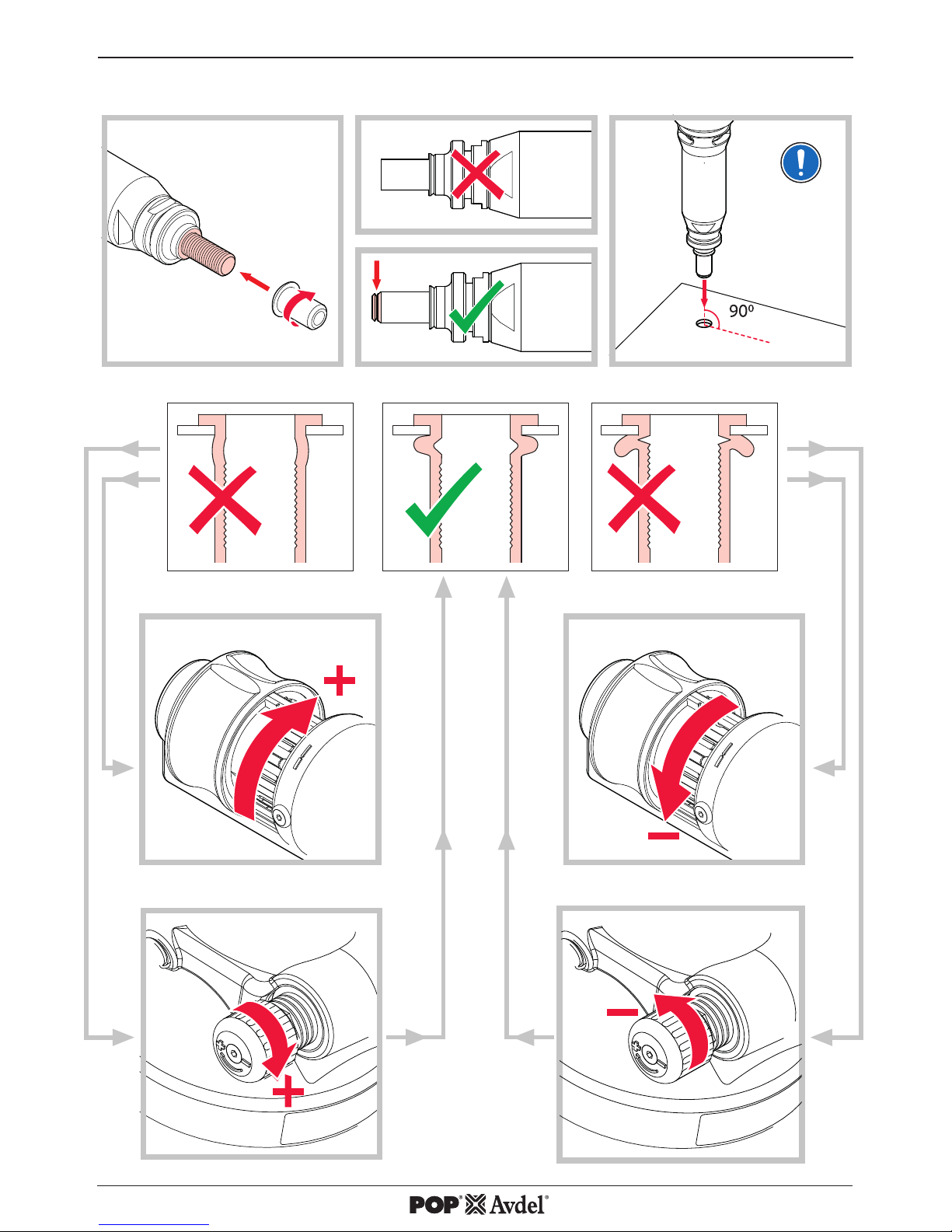
4.3.1. Stroke Adjustment (see Fig. 1A & 3).
To use this tool in stroke set operation, screw the Pressure Regulator 19 fully in to achieve full pressure then
adjust Stroke Setter to the desired stroke length:
• Open Stroke Slider 11.
• The Stroke Locking Pin 13 will be released.
• Directional arrows indicate stoke direction.
• Increase the stroke from the minimum until optimum deformation is obtained.
• The scale gives an indication of the current stroke length.
• Increments 12 shown are 3, 5 and 7mm on one side and 4 and 6mm on the opposite.
• Line the rear of the Stroke Setter 14 up with these marks to achieve desired stroke length.
• Each Recess 15 on the Stroke Setter 14 is equal to +- 0.1mm of stroke.
• Close the Stroke Slider 11 before using in the application environment.
• The Stroke Lock will activate when the Stroke Slider 11 is closed when the tool is in the upright position
• The tool is now ready to operate.
4.3.2. Pressure Adjustment (see Fig. 1B & 3).
To use this tool in pressure set operation, wind the Stroke Setter 14 to 7mm, then screw the Pressure
Regulator 19 fully out to achieve minimum pressure then adjust to the desired pressure:
• Initially the Blind Rivet Nut will not deform and the tool will spin o .
• Screw in the Pressure Regulator 19 by 1 groove on the regulator body and test.
• Repeat the operation with the Pressure Regulator 19 until optimum deformation is obtained.
• 1 notch on the Pressure Regulator 19 is equivalent to approximately 20N of pulling force.
• After a successful Blind Rivet Nut deformation, check the Blind Rivet Nut and increase the force if
necessary.
• Increase by 1-2 notches extra to allow for variation in the Blind Rivet Nuts.
• The tool is now ready to operate.
5. Operating Procedure
Installing a Blind Rivet Nut (see Fig. 3).
To install a Blind Rivet Nut.
• Check that the correct Blind Rivet Nut has been selected.
• Push Blind Rivet Nut into the application.
• Check Nose Assembly is at right angle (90°) to the work.
• Push onto the Blind Rivet Nut with the tool to spin on.
• Once fully and correctly inserted, depress tool Trigger 20 switch to start installation cycle.
• Hold the Trigger 20 until the Blind Rivet Nut is completely set and the tool has disengaged completely.
In the event a Blind Rivet Nut becomes jammed in an application press the Manual Reverse Trigger 17 to
reverse the Mandrel 1 and spin o the Blind Rivet Nut. Alternately disconnect from the air supply and use the
4mm Pin Punch 21 supplied in the Maintenance Kit to wind o the Mandrel through the Nose Casing 4 shown
in the gure 1.
CAUTION - do not attempt to force the installation of an insert as this will cause damage to the tool and/or
application.
12
ENGLISH
Page 13

6. Servicing the Tool
Regular servicing must be carried out by trained personnel and a comprehensive inspection performed
annually or every 500,000 cycles, whichever is sooner.
Cleaning and Maintenance
DISCONNECT AIR SUPPLY
Nose assemblies should be serviced at weekly intervals or every 5,000 cycles
CAUTION - Blow dirt and dust out of the main housing with dry air as often as dirt is seen collecting in and
around the air vents where the Pneumatic Cylinder connects to the plastic Handle Assembly. Wear approved eye
protection and approved dust mask when performing this procedure.
CAUTION - Never use solvents or other harsh chemicals for cleaning the non-metallic parts of the tool. These
chemicals may weaken the materials used in these parts.
• Disconnect the air supply
• Remove the complete nose assembly using the reverse procedure to the Fitting Instructions page 10(4.1).
• Any worn or damaged part must be replaced by a new part.
• Particularly check wear on Mandrel.
• Assemble according to tting instructions.
6.1 Daily Servicing
• Check for air leaks. If damaged, hoses and couplings must be replaced by new items.
• Check that the Nose Assembly is correct and tted properly.
• Check if the stroke of the tool is adequate to place selected Blind Rivet Nut. See Stroke Adjustment page
12 (4.3.1.).
• Inspect the Mandrel 1 in the nose assembly for wear or damage. If any, replace.
6.2 Weekly Servicing
• Check for oil leaks and air leaks on air supply hose and ttings and tool.
• With the tool laid horizontally, open “Oil Plug” and check oil level, if low re-prime, refer to “Service manual,
Section 6”.
For full servicing, troubleshooting and maintenance instructions please refer to Service Manual 07900-09302.
Maintenance Kit 07900-09301
Part Number Description Qty
07900-00624 4mm Pin Punch 1
07900-00632 17mm/19mm Spanner 1
07900-00225 5mm Hexagonal Wrench 1
13
ENGLISH
Page 14

7. Declaration of Conformity
We, Avdel UK Limited, Stanley House, Works Road, Letchworth Garden City, Hertfordshire,
SG6 1JY UNITED KINGDOM, declare under our sole responsibility that the product:
Description ProSertTM XTN20 Hydro-Pneumatic Blind Rivet Nut Tool
Brand/Model POP-Avdel 74202
Serial No.
to which this declaration relates is in conformity with the following standards:
ISO 12100:2010 EN ISO 28927-5:2009
EN ISO 11202:2010 EN ISO 3744:2010
EN ISO 4413:2010 EN ISO 11148-1:2011
EN ISO 4414:2010 EN 28662-1: 1993
Technical documentation is compiled in accordance with Annex 1, section 1.7.4.1,
in accordance with the following Directive:
2006/42/EC The Machinery Directive
UK Statutory Instruments 2008 No 1597 - The Supply of Machinery (Safety) Regulations refers.
A. K. Seewraj
Technology Manager – EU Blind Fastening
Avdel UK Limited, Stanley House, Works Road, Letchworth Garden City,
Hertfordshire, SG6 1JY UNITED KINGDOM
Place of issue: Letchworth Garden City
Date of issue: 01-04-2015
This machinery is in conformity with
Machinery Directive 2006/42/EC
Original Instruction
14
ENGLISH
Page 15

8. Protect your Investment!
POP®Avdel® BLIND RIVET NUT TOOL WARRANTY
STANLEY Engineered Fastening warrants that all power tools have been carefully manufactured and that they
will be free from defect in material and workmanship under normal use and service for a period of one (1)
year.
This warranty applies to the rst time purchaser of the tool for original use only.
Exclusions:
Normal wear and tear.
Periodic maintenance, repair and replacement parts due to normal wear and tear are excluded from coverage.
Abuse & Misuse.
Defect or damage that results from improper operation, storage, misuse or abuse, accident or neglect, such as
physical damage are excluded from coverage.
Unauthorized Service or Modi cation.
Defects or damages resulting from service, testing adjustment, installation, maintenance, alteration or
modi cation in any way by anyone other than STANLEY Engineered Fastening, or its authorized service
centres, are excluded from coverage.
All other warranties, whether expressed or implied, including any warranties of merchantability or tness for
purpose are hereby excluded.
Should this tool fail to meet the warranty, promptly return the tool to our factory authorized service centre
location nearest you. For a list of POP®Avdel®Authorized Service Centres in the US or Canada, contact us at our
toll free number (877)364 2781.
Outside the US and Canada, visit our website www.StanleyEngineeredFastening.com to find your nearest
STANLEY Engineered Fastening location.
STANLEY Engineered Fastening will then replace, free of charge, any part or parts found by us to be defective
due to faulty material or workmanship, and return the tool prepaid. This represents our sole obligation under this
warranty. In no event shall STANLEY Engineered Fastening be liable for any consequential or special damages
arising out of the purchase or use of this tool.
Register Your Blind Rivet Nut Tool online.
To register your warranty online, visit us
http://www.stanleyengineeredfastening.com/popavdel-powertools/warranty-card
Thank you for choosing an STANLEY Engineered Fastening’s POP®Avdel® Brand tool.
15
ENGLISH
Page 16

Page 17

ÍNDICE
PÁGINA
1. Denições de Segurança 6
2. Especicações 8
2.1 Especicações da Ferramenta 8
2.2 Conteúdo da Embalagem 8
2.3 Componentes Principais 9
3. Ajuste da Ferramenta 10
4. Instruções Operacionais 10
4.1 Nariz 10
4.2 Alimentação de Ar 11
4.3 Instruções de Ajuste 11
5. Procedimento Operacional 12
6. Manutenção da Ferramenta 13
6.1 Manutenção Diária 13
6.2 Manutenção Semanal 13
7. Certicado de Conformidade 14
8. Proteja seu investimento. Registro de garantia 15
© 2015 Stanley Black & Decker, Inc.
Todos os direitos reservados.
As informações fornecidas aqui não podem ser reproduzidas e/ou publicadas de qualquer forma e através
de qualquer meio (eletronica ou mecanicamente) sem a permissão prévia explícita e por escrito da STANLEY
Engineered Fastening. As informações fornecidas baseiam-se em dados conhecidos no momento do
lançamento deste produto. A STANLEY Engineered Fastening segue uma política de melhoria contínua de
produtos, portanto, seus produtos podem sofrer alterações. As informações fornecidas aqui aplicam-se ao
produto entregue pela STANLEY Engineered Fastening. Logo, a STANLEY Engineered Fastening não pode ser
responsabilizada por qualquer dano resultante de desvios das especi cações originais do produto.
As informações disponíveis foram elaboradas com o máximo cuidado. No entanto, a STANLEY Engineered
Fastening não aceitará responsabilidades por quaisquer falhas de informação nem pelas consequências
resultantes. A STANLEY Engineered Fastening não aceitará qualquer responsabilidade por danos provenientes
de atividades executadas por terceiros. Os nomes de trabalho, nomes comerciais, marcas comerciais
registradas etc. utilizadas pela STANLEY Engineered Fastening não devem ser consideradas livres nos termos
da legislação referentes à proteção das marcas.
Tradução da Instrução original
5
BRASILEIRO
Page 18

A
Este manual de instruções deve ser lido por qualquer pessoa que irá instalar ou operar esta ferramenta com
atenção especial para as seguintes regras de segurança.
1. De nições de Segurança
As de nições abaixo descrevem o nível de gravidade representado em cada letra. Por favor, leia o manual
e preste atenção nestes símbolos.
PD PERIGO: Indica uma situação de perigo iminente que, se não for evitada, poderá resultar em morte ou
ferimentos graves.
D AVISO: Indica uma situação potencialmente perigosa que, se não for evitada, poderá resultar em morte
ou ferimentos graves.
D CUIDADO: Indica uma situação potencialmente perigosa que, se não for evitada, talvez resulte em ferimentos
leves ou moderados.
CUIDADO: Usado sem o símbolo de alerta de segurança indica uma situação potencialmente perigosa que,
se não for evitada, poderá resultar em danos materiais.
A operação ou manutenção inadequada deste produto pode resultar em ferimentos graves e danos
materiais. Leia e entenda todos os avisos e instruções operacionais antes de utilizar este equipamento.
Ao utilizar ferramentas, siga sempre as precauções básicas de segurança para reduzir o risco de lesões
corporais.
GUARDE ESTAS INSTRUÇÕES.
AVISO:
1. Não use o produto fora de sua aplicação prevista no projeto da Rebitadeira de Porca Rebite Cega da STANLEY
Engineered Fastening.
2. Use apenas peças, parafusos, e acessórios recomendados pelo fabricante.
3. Nunca modi que a ferramenta. Qualquer modi cação na ferramenta realizada pelo cliente será de sua inteira
responsabilidade e invalidará quaisquer garantias aplicáveis.
4. Antes de usar, veri que se há desalinhamentos ou junções de peças móveis, quebra de peças e qualquer outras
condições que afetem o funcionamento da ferramenta. Se ela estiver dani cada, envie-a à manutenção antes
de usá-la. Remova chaves de ajuste ou chaves xa antes de usá-la.
5. A ferramenta deve ser sempre mantida em condição operacional segura, e examinada por pessoal treinado
em intervalos regulares quanto ao seu funcionamento e à presença de danos. Qualquer procedimento de
desmontagem deve ser realizado apenas por pessoal treinado. Não desmonte esta ferramenta sem consultar
antes as instruções de manutenção.
6. A pressão operacional de alimentação não deve exceder 7 bar (100 PSI).
BC
7. Os operadores e outras pessoas na área de trabalho devem usar óculos de segurança aprovados
ANSI Z87.1 CAN/CSA Z94.3 com proteções laterais. Sempre use óculos de segurança e protetores auriculares
durante a operação.
6
BRASILEIRO
Page 19

8. Vista-se adequadamente Não use roupas largas ou joias. Mantenha cabelos, roupas e luvas longe das peças
móveis. Roupas largas, joias ou cabelos longos podem car presos nas peças móveis.
9. Não opere uma ferramenta direcionada a uma pessoa(s).
10. NÃO OPERE a ferramenta sem o invólucro do nariz.
11. Tenha uma base rme ou uma posição estável antes de operar a ferramenta.
12. Antes do uso, veri que se há danos nas tubulações de ar, todas as conexões precisam estar seguras. Não deixe
cair objetos pesados nas mangueiras. Um forte impacto pode causar danos internos e levar a avarias precoces
da mangueira.
13. Não levante a ferramenta pelas mangueiras. Sempre utilize o cabo da ferramenta.
14. Orifícios de ventilação não devem estar bloqueadas ou cobertos.
15. Desligue a mangueira de ar da ferramenta antes de executar qualquer manutenção, tentar ajustar, encaixar ou
remover componentes do nariz.
16. Mantenha cabos de ferramentas secos, limpos e sem óleo e graxa.
17. Ao transportar a ferramenta de um lugar a outro, mantenha as mãos afastadas do gatilho para evitar um
acionamento acidental.
18. Nunca deixe a ferramenta funcionando sozinha. Desconecte as mangueiras de ar quando a ferramenta não
estiver em uso.
19. Antes de operar a ferramenta, os seus operadores precisam limpar as mãos adequadamente.
20. Não derrube a ferramenta ou a use como martelo.
21. Não deixe que o sistema hidráulico da ferramenta que sujo ou com outros materiais, pois isso pode causar um
funcionamento incorreto.
Uma das políticas da STANLEY Engineered Fastening
é desenvolver e aperfeiçoar continuamente o produto,
por isso reservamos-nos o direito de mudar as especi cações
de qualquer produto sem aviso prévio.
7
BRASILEIRO
Page 20

Os itens com um * podem requerer um kit adaptador de mandril (74202-02200 encontrado no Manual de Acessórios 07900-01073).
Uma rebitadeira completa ProSert XTN20 (74202) é composta pela ferramenta de base (número de peça 74202-02000)
e o conjunto do nariz apropriado para a inserção.
Força de Tração: Tração @ pressão de tração declarada 5.0 bar 17,65 kN 3968 lbf
Pressão de
Alimentação de Ar:
Min/Máx. 5-7 bar 72.5-101.5 lbf/in
2
Pressão do Óleo: Tração (máx.) 230 bar 3336 lbf/in
2
Curso: Curso do pistão 3-7 mm 0,118-0,275 in
Peso: Incluindo o nariz 1,59 kg 3,50 lb
Nível do Nariz: Incerteza ruído: K=3dB(A) <75 dB(A) <75 dB(A)
Vibração: Incerteza vibrações: K=0.1 m/s² <2.5 m/s
2
<8 ft/s
2
Velocidade do Motor: Avanço & Recuo 2000rpm 2000rpm
2. Especi cações
SOB NENHUMA CIRCUNSTÂNCIA, DEVE-SE REALIZR A MANUTENÇÃO OU O REPARO SEPARADAMENTE
SEM A ALTERAÇÃO DO NARIZ.
A rebitadeira ProSert XTN20 hidropneumática é projetada para aplicar Porcas Rebites Cegas da STANLEY
Engineered Fastening através do ajuste da força e/ou do curso.
A rebitadeira XTN20 ProSert é usada para colocar Porcas Rebites Cegas de M3 a M10 quando acopladas
ao nariz. O nariz também está disponível para aplicações de tamanho de roscas de polegadas UNC e UNF.
As instruções de segurança têm de ser sempre seguidas.
2.1. Especi cações da Ferramenta
2.2. A embalagem contém:
• 1 Porca Rebite Cega XTN20
• 1 conjunto M4, M5, M6, M8 do Nariz e Mandris
• 1 Manual de Instruções Impresso
• 1 Kit de Manutenção
Características
Adicionais:
Modo operacional Tração-a-Força Sim
Modo operacional Tração-a-Curso Sim
Modo automático Girar Atarraxando/
Desatarraxando
Sim
Conexões de mandril livres Sim
Desligamento da Reversão Manual Sim
Vedadores de Lábios Hidráulicos & Anel-O Sim
8
BRASILEIRO
Material: - Alumínio Aço
Aço inoxidável
Linha de
ProdutosAvdel®:
Eurosert® - M3-M10 M4-M5
Thin Sheet Nutsert® M3-M10 M3-M10 M3-M10
DK/DL M4-M10 Euro Hexsert®/Hexsert® - M3-M8 M6
High Strength Hexsert® - M6-M8 Squaresert® - M5-M8 -
POP Nut®
Linha de Produtos:
Porca Padrão* M3-M10 M3-M8 M4-M6
Porca Recartilhada* M4-M8 M4-M6 Porca Cega* M3-M10 M3-M8 M4-M6
Porca Sextavada* M4-M8 M4-M8 M4-M6
Porca Tetra* M4-M8 M4-M8 Parafuso HB* M6-M8 M6-M8 Porca de tubo* M6 M6 -
Page 21

2.3. Componentes Principais
ref. g. 1 & 2 Novo pedido
No. de peças de reposição Qtde
1 Mandril
M4 07555-09004 1
M5 07555-09005 1
M6 07555-09006 1
M8 07555-09008 1
2 Ponta do nariz
M4 07555-00904 1
M5 07555-00905 1
M6 07555-00906 1
M8 07555-00908 1
3 Contraporca - 07555-00901 1
4 Invólucro do nariz - 74202-02021 1
5 Porca Castelo - 74202-02022 1
6 Manga de Redução
M4 07555-09104 1
M5 07555-09105 1
M6 07555-09106 1
M8 07555-09108 1
7 Eixo de Comando
M4 07555-01004 1
M5 07555-01005 1
M6 07555-01006 1
M8 07555-01008 1
8 Adaptador de Mandril 74202-02023 1
9 Haste do nariz 74202-02039 10 Anel de Suspensão 74202-02012 1
11 Atuador de Curso 74202-02092 1
12 Marcações de Indicação de Curso - 13 Pino-Trava de Curso 74202-02095 1
14 Fixador de Curso 74202-02010 1
15 Encaixe do Fixador de Curso - 16 Dispositivo de Entrada de Ar 74202-02103 1
17 Gatilho Reverso Manual 74202-02030 1
18 Trava de Regulagem 74202-02038 1
19 Regulador de Pressão 74202-02037 1
20 Gatilho 74202-02020 1
21 Extrator 07900-00624 1
Conjunto do nariz completo
M4 07555-09884
M5 07555-09885
M6 07555-09886
M8 07555-09888
* Todos os tamanhos são fornecidos com Contraporcas (3) 07555-00901.
Para tamanhos adicionais, por favor acesse: www.StanleyEngineeredFastening.com
9
BRASILEIRO
Page 22

3. Ajuste da Ferramenta
PD IMPORTANTE - LEIA AS INSTRUÇÕES NA PÁG. 6 e 7 CUIDADOSAMENTE ANTES DE INICIAR
O FUNCIONAMENTO.
Antes do Uso
• Selecione o nariz com o tamanho correto e instale-o.
• Conecte a rebitadeira à alimentação de ar. Teste os ciclos de tração e retorno apertando e soltando
o gatilho 20.
• Ajuste a ferramenta para o curso/pressão desejada.
PD CUIDADO - a pressão de alimentação correta é importante para um funcionamento apropriado da
ferramenta. Lesões corporais ou danos ao equipamento podem ocorrer sem as pressões corretas. A pressão de
alimentação não deve ser superior à aquela descrita nas especi cações da ferramenta.
4. Instruções Operacionais
PD IMPORTANTE - LEIA AS INSTRUÇÕES NA PÁG. 6 e 7 CUIDADOSAMENTE ANTES DE INICIAR
O FUNCIONAMENTO.
PD IMPORTANTE - A ALIMENTAÇÃO DE AR PRECISA SER DESLIGADA OU DESCONECTADA ANTES
DE CONECTAR OU REMOVER O CONJUNTO DO NARIZ.
4.1 Nariz (veja Fig.2).
Instruções de Montagem
Os números dos itens em negrito referem-se aos componentes do nariz na Fig. 1.
• A alimentação de ar precisa ser desconectada
• Se ainda for apropriado, remova o Invólucro do nariz 4 e a Porca castelo 5 ao puxar a mola carregada
da Haste do nariz 9.
• Insira o Eixo de Comando 7 no Adaptador de Mandril 8.
• Encaixe o Mandril 1 dentro do Eixo de Comando 7.
• Insira a Manga de Redução 6 (se especi cada) na Porca Castelo 5.
• Atarraxe a Porca Castelo 5 no Adaptador de Mandril 8 puxando para trás a mola colocada na Haste do
Nariz 9. Aperte a Porca Castelo 5 no sentido horário.
• Segurando a ferramenta, atarraxe o Invólucro do Nariz 4 e a Ponta do Nariz 2 com a Contraporca 3.
• Deve-se executar a operação inversa para desmontagem do equipamento.
Com a ferramenta ainda desconectada da alimentação de ar, atarraxe manualmente a Porca Rebite Cega no
Mandril.
• Posicione a Ponta do Nariz 2 no Invólucro do Nariz 4 e trave-o com a Contraporca 3 para que o Mandril 1
que ligeiramente saliente para fora da Porca de Rebite Cego.
• Trave a Contraporta 3, girando-a no sentido horário com uma chave de porca*. Remova a Porca Rebite
Cega do Mandril.
*Refere-se aos itens pertencentes ao Kit de Manutenção 07900-09301 da pág.13.
10
BRASILEIRO
Page 23

4.2 Alimentação de Ar
• Todas as ferramentas são operadas com ar comprimido a uma pressão mínima de 5.0 bar.
• Reguladores de pressão e os sistemas de lubri cação/ ltragem automáticos devem ser usados na fonte
de alimentação de ar a 3 metros da ferramenta (ver Fig. 4).
• Mangueiras de alimentação de ar terão um nível mínimo de pressão efetiva operacional de 150% da
pressão máxima produzida no sistema ou 10 bar, qualquer outra maior.
• As mangueiras de ar devem ser à prova de óleo, ter um exterior resistente à abrasão, e blindadas, onde as
condições operacionais possam dani cá-las.
• Todas as mangueiras de ar PRECISAM ter um diâmetro interno mínimo de 6,4 mm.
Se o sistema acima não estiver disponível, você poderá usar a seguinte alternativa:
• Antes do uso ou na primeira colocação em serviço da ferramenta, coloque algumas gotas de óleo
lubri cante leve e limpo na entrada de ar da ferramenta, se não houver nenhum lubri cador montado
na alimentação de ar. Se a ferramenta estiver em uso contínuo, a mangueira de ar deve ser desligada da
fonte de alimentação de ar e a ferramenta lubri cada a cada duas até três horas.
• Veri car se há vazamentos de ar. Mangueiras e acoplamentos precisam ser substituídos por novos se
estiverem dani cados.
• Se não houver um ltro no regulador de pressão, purgue o tubo de ar para limpá-lo de água e sujeira
acumuladas antes de conectar a mangueira de ar na ferramenta.
4.3 Instruções de Ajuste
• A característica de ajuste de curso é usada principalmente para M3-M4 de tamanhos de inserções
menores.
• Se estiver ajustando a ferramenta para um curso ideal, gire o Fixador de Curso para frente no curso
mínimo (3 mm) e o Regulador de Pressão 19 para frente no ajuste máximo.
• Se estiver ajustando a ferramenta para uma pressão ideal, gire o Fixador de Curso para trás no curso
máximo (7mm) e o Regulador de Pressão 19 para trás no ajuste mínimo.
Ao manejar diferentes espessuras de aderência, sempre se recomenda que a ferramenta seja con gurada para
uma pressão otimizada, não para o curso otimizado. Use essa condição máxima de aderência para otimizar
a pressão.
Fig. 4
CONEXÃO DE GÁS 1/4"
LUBRIFICADOR
REGULADOR DE PRESSÃO
E FILTRO DRENAR
DIARIAMENTE
VÁLVULA LIMITADORA
USADA DURANTE
A MANUTENÇÃO DE FILTRO/
REGULADOR OU UNIDADES
DE LUBRIFICAÇÃO
FONTE DE
ALIMENTAÇÃO
3 METROS NO MÁXIMO
11
BRASILEIRO
Page 24

4.3.1. Ajuste de Curso (veja Fig. 1A e 3).
Para usar esta ferramenta em operação de ajuste de curso, atarraxe o Regulador de Pressão 19 completamente
até alcançar a pressão máxima, então ajuste o Fixador de Curso para o comprimento do curso desejado:
• Abra o Atuador de Curso 11.
• O Pino-Trava de Curso 13 será solto.
• As setas indicam a direção de curso.
• Aumente o curso do mínimo até obter a deformação ideal.
• A escala indica o comprimento do curso atual.
• Acréscimos 12 mostrados são de 3, 5 e 7 mm de um lado e 4 e 6 mm no lado oposto.
• Alinhe a parte de trás do Fixador de Curso de 14 para cima com essas marcas para alcançar
o comprimento do curso desejado.
• Cada Encaixe 15 no Fixador de Curso 14 é igual a + - 0,1 mm de curso.
• Feche o Atuador de Curso 11 antes de usar no ambiente de aplicação.
• O Pino-Trava de Curso irá se ativar quando o Atuador de Curso 11 for fechado, quando a ferramenta
estiver na posição vertical
• Agora a ferramenta está pronta para funcionar.
4.3.2. Ajuste de Pressão (veja Fig. 1B e 3).
Para usar esta ferramenta na operação do conjunto de pressão, enrole o Fixador de curso 14 a 7 mm, depois
parafuso o Regulador de pressão 19 para alcançar a pressão mínima, e depois ajuste a pressão desejada:
• Inicialmente a Porca Rebite Cega não se deformará e a ferramenta irá girar desatarraxando.
• Atarraxe o Regulador de Pressão 19 em 1 ranhura no corpo do regulador, e teste.
• Repita a operação com o Regulador de Pressão 19 até obter uma deformação ideal.
• 1 entalhe no Regulador de Pressão 19 é equivalente a aproximadamente 20N de força de tração.
• Depois de obter uma deformação correta da Porca Rebite Cega, examine-a, e se necessário, aumente
a força.
• Aumente em 1-2 entalhes extras para permitir variações nas Porcas Rebites Cegas.
• Agora a ferramenta está pronta para funcionar.
5. Procedimento Operacional
Instalando uma Porca Rebite Cega (veja Fig. 3).
Para instalar uma Porca Rebite Cega.
• Con ra se escolheu a Porca Rebite Cega correta.
• Empurre a Porca Rebite Cega para dentro da aplicação.
• Con ra se o Conjunto do Nariz está no ângulo correto (90°) para operar.
• Empurre para a ferramenta a Porca Rebite Cega para girar atarraxando.
• Depois de inserida completa e corretamente, aperte o Gatilho 20 para iniciar o ciclo de instalação.
• Segure o Gatilho 20 até que a Porca Rebite Cega esteja completamente ajustada e a ferramenta
totalmente desengatada.
Se a Porca Rebite Cega car emperrada em uma aplicação, pressione o Gatilho Reverso Manul 17 para reverter
o Mandril 1 e girar desatarraxando a Porca Rebite Cega. Ou desconecte o fornecimento de ar e use o Punção
Extrator 4 mm 21 fornecido no Kit de Manutenção para girar para trás o mandril através do Invólucro do Nariz
4 mostrado na gura 1.
PD CUIDADO - não tente forçar a instalação de uma inserção, pois isto causará danos à ferramenta e/ou
aplicação.
12
BRASILEIRO
Page 25

6. Manutenção da Ferramenta
Manutenções regulares têm de ser executadas por pessoal treinado e uma inspeção abrangente precisa ser
realizada anualmente ou a cada 500.000 ciclos ou anteriormente.
Limpeza e Manutenção
PD DESCONECTE A ALIMENTAÇÃO DE AR
Os conjuntos do nariz devem passar por manutenção semanalmente ou a cada 5.000 ciclos.
D CUIDADO - Ejete ar seco, tirando a sujeira e a poeira do invólucro principal sempre quando houver acúmulo
dentro e ao redor dos respiros de ar e no local onde o Cilindro Pneumático se conecta aos Conjuntos do Cabo de
plástico. Use proteções para os olhos e máscaras contra poeira aprovadas ao realizar este procedimento.
D P CUIDADO - Nunca use solventes ou outros produtos químicos para a limpeza das partes não metálicas da
ferramenta. Esses produtos químicos podem enfraquecer os materiais utilizados nestas partes.
• Desligue a alimentação de ar
• Remova conjunto do nariz completamente, realizando o procedimento inverso descrito na página
10 Instruções de Montagem (4.1).
• Toda parte desgastada ou dani cada precisa ser substituída por uma nova.
• Veri que principalmente se há desgastes no Mandril.
• Monte de acordo com as Instruções de Montagem.
6.1 Manutenção Diária
• Veri que se há vazamentos de ar. Mangueiras e acoplamentos precisam ser substituídos por novos se
estiverem dani cados.
• Veri que se o Conjunto do Nariz está correto e montado apropriadamente.
• Veri que se o curso da ferramenta está adequado para colocar a Porca Rebite Cega. Veja Ajuste de Curso
na página 12 (4.3.1.).
• Inspecione o Mandril 1 no conjunto do nariz em relação a danos ou desgaste. Se houver, troque-o.
6.2 Manutenção Semanal
• Veri que se há vazamentos de óleo e ar na mangueira na mangueira e nas conexões de alimentação de
ar e na ferramenta.
• Com a ferramenta posicionada na horizontal, abra o “Plug do óleo” e veri que o nível de óleo, se estiver
baixo complete, consulte o “Manual de serviço, Seção 6.”
Para obter instruções completas para serviços, avarias simples e manutenção, por favor consultar o Manual
de Manutenção 07900-09302.
Kit de Manutenção 07900-09301
Número de Peça Descrição Qtde
07900-00624 Punção Extrator 4 mm 1
07900-00632 Chave de porca 17mm/19mm 1
07900-00225 Chave Allen 5mm 1
13
BRASILEIRO
Page 26

7. Declaração de Conformidade
Nós, Avdel UK Limited, Stanley House, Works Road, Letchworth Garden City, Hertfordshire,
SG6 1JY UNITED KINGDOM, declaramos sob nossa única responsabilidade que o produto:
Descrição ProSertTM XTN20 Rebitadeira de Porca Rebite Cega
Marca/Modelo POP-Avdel 74202
No. de Série
ao qual esta declaração se refere, está em conformidade com as seguintes normas:
ISO 12100:2010 EN ISO 28927-5:2009
EN ISO 11202:2010 EN ISO 3744:2010
EN ISO 4413:2010 EN 792-13:2000+A1:2008
EN ISO 4414:2010 EN 28662-1: 1993
A documentação técnica está compilada em conformidade com o Anexo 1, seção 1.7.4.1,
de acordo com a seguinte diretriz:
2006/42/CE A Diretriz de Máquinas
Instrumentos do Estatuto - Reino Unido 2008 No. 1597 - As Normas de Fornecimento de Máquinas (Segurança).
A. K. Seewraj
Gerente de Tecnologia - Fixação Mecânica Cega - CE
Nós, Avdel UK Limited, Stanley House, Works Road, Letchworth Garden City, Hertfordshire,
Hertfordshire, SG6 1JY UNITED KINGDOM
Local de publicação: Letchworth Garden City
Data de publicação: 01.04.2015
Esta máquina está em conformidade com
a Diretriz de Máquinas 2006/42/CE
Tradução da Instrução original
14
BRASILEIRO
Page 27

8. Proteja seu investimento!
POP®Avdel® MÁQUINA DE REBITAR REBITE - GARANTIA
STANLEY Engineered Fastening garante que todas as ferramentas foram cuidadosamente fabricadas
e não apresentarão defeitos de material nem de fabricação no seu uso normal e para serviços por um período
de um (1) ano.
Esta garantia aplica-se ao primeiro comprador da máquina e para apenas para o seu uso original.
Exclusões:
Uso e desgaste normal.
Manutenções periódicas, reparos e reposições de peças devido ao uso e ao desgaste normal estão excluídos
da cobertura da garantia.
Abuso e uso indevido.
Defeitos ou danos resultados de operação incorreta, armazenamento e uso indevidos ou abuso, acidente ou
negligência, como danos físicos, estão excluídos da cobertura da garantia.
Manutenção ou modi cações não autorizadas.
Defeitos ou danos resultantes de operações, testes, ajustes, instalações, manutenções, alterações ou
modi cações de qualquer forma não realizadas pelo pessoal da STANLEY Engineered Fastening, ou de seus
centros de serviços autorizados, estão excluídos da cobertura da garantia.
Todas as outras garantias, explícitas ou implícitas, incluindo quaisquer garantias de comercialização ou
adequação para qualquer propósito, estão excluídas.
Se a máquina não atende aos requisitos de garantia, devolva-a imediatamente ao nosso centro de serviços
autorizados de fábrica mais próximo. Para uma lista de centros de serviços autorizados da POP®Avdel® nos
EUA or Canadá, contacte-nos pelo número gratuito (877)364 2781.
Fora dos EUA e Canada, visite nosso website www.StanleyEngineeredFastening.com para encontrar
o centro de serviços STANLEY Engineered Fastening mais próximo.
A STANLEY Engineered Fastening irá então trocar, gratuitamente , qualquer peça ou peças ,as quais
apresentam defeitos devido a uma falha de material ou de fabricação e, devolverá a máquina pré- paga.
Isto representa nossa obrigação única sob esta garantia. Em nenhuma circunstância a STANLEY Engineered
Fastening deverá ser responsabilizada por quaisquer danos resultantes ou especiais oriundos da compra ou
uso desta máquina.
Registre on-line sua Máquina de Rebitar Rebite.
Para registrar sua garantia on-line, acesse:
http://www.stanleyengineeredfastening.com/popavdel-powertools/warranty-card
Muito obrigado por escolher uma máquina da marca STANLEY Engineered Fastening POP®Avdel®.
15
BRASILEIRO
Page 28

Page 29

CONTENIDO
PÁGINA
1. Deniciones de seguridad 6
2. Especicaciones 8
2.1 Especicaciones de la herramienta de colocación 8
2.2 Contenido del embalaje 8
2.3 Lista de componentes principales 9
3. Montaje de la herramienta 10
4. Instrucciones de funcionamiento 10
4.1 Boquillas 10
4.2 Suministro de aire 11
4.3 Instrucciones de regulación 11
5. Procedimiento de trabajo 12
6. Mantenimiento de la herramienta 13
6.1 Mantenimiento diario 13
6.2 Mantenimiento semanal 13
7. Declaración de conformidad 14
8. Proteja su inversión . Registro de garantía 15
© 2015 Stanley Black & Decker, Inc.
Todos los derechos reservados.
La información suministrada no puede reproducirse ni hacerse pública en ningún modo o ni a través de
ningún medio (ni en modo electrónico ni impreso) sin expresa autorización previa de STANLEY Engineered
Fastening. La información suministrada se proporciona sobre la base de los datos conocidos en el momento
de la presentación de este producto. STANLEY Engineered Fastening aplica una política de mejora continua de
producto, por lo tanto, los productos están sujetos a modi caciones. La información facilitada es de aplicación
al producto tal y como ha sido entregado por STANLEY Engineered Fastening. Por tanto, STANLEY Engineered
Fastening no se responsabilizará de ningún daño derivado de disconformidades con las especi caciones
originales del producto.
La información disponible ha sido elaborada con extrema diligencia. No obstante, STANLEY Engineered
Fastening no asumirá responsabilidad alguna en relación con cualesquiera fallos en la información
o con las consecuencias que pudieran derivarse de la misma. STANLEY Engineered Fastening no asumirá
responsabilidad alguna por daños derivados de actividades efectuadas por terceros. Los nombres
profesionales, los nombres comerciales, las marcas comerciales registradas, etc. usadas por STANLEY
Engineered Fastening no deberán considerarse libres, de conformidad con la legislación relativa a la
protección de marcas comerciales.
Traducción de la Instrucción Original
5
ESPAÑOL
Page 30

A
Las personas que instalen o hagan funcionar la herramienta deberán leer el manual de instrucciones,
prestando especial atención a las siguientes normas de seguridad.
1. De niciones de seguridad
Las de niciones que guran a continuación describen el nivel de gravedad de cada término de alarma.
Lea el manual y preste atención a estos símbolos.
D PELIGRO: Indica una situación de peligro inminente que, de no evitarse, podría ocasionar la muerte
o una lesión grave.
D ADVERTENCIA: Indica una situación potencialmente peligrosa que, de no evitarse, podría ocasionar
la muerte o una lesión grave.
D PRECAUCIÓN: Indica una situación potencialmente peligrosa que, de no evitarse, podría ocasionar una lesión
de poca o moderada gravedad.
PRECAUCIÓN: Usado sin el símbolo de alerta de seguridad indica una situación potencialmente peligrosa que,
de no evitarse, podría causar daños materiales.
El funcionamiento o el mantenimiento inadecuado de este producto podría causar lesiones graves o daños
materiales. Lea y comprenda todas las advertencias e instrucciones de funcionamiento antes de usar este
equipo. Cuando utilice herramientas mecánicas, deberá tomar siempre todas las precauciones básicas
de seguridad para reducir el riesgo de daños personales.
GUARDE LAS PRESENTES INSTRUCCIONES.
ADVERTENCIA:
1. No use la herramienta para otros nes distintos al previsto de colocación de tuercas remachables
de STANLEY Engineered Fastening.
2. Use solamente piezas, remaches y accesorios recomendados por el fabricante.
3. No altere la herramienta de ningún modo. Si el cliente aporta cualquier modi cación a la herramienta,
se responsabilizará totalmente de ello y perderán validez todas las garantías aplicables.
4. Antes del uso, compruebe que no haya ninguna desalineación o bloqueo de las piezas móviles, rotura de piezas
y cualquier otra condición que pudiera afectar al funcionamiento de la herramienta. Si la herramienta está
dañada, llévela a reparar antes de utilizarla. Extraiga eventuales llaves o pinzas de ajuste antes del uso.
5. La máquina debe mantenerse en condiciones de trabajo seguras todo el tiempo, debe comprobarse a
intervalos regulares que no presente daños y debe ser utilizada por personal capacitado. El procedimiento de
desmontaje deberá ser realizado por personal capacitado. No desmonte esta herramienta sin consultar antes
las instrucciones de mantenimiento.
6. El suministro de aire de trabajo no debe superar los 7 bar (100 PSI).
BC
7. Los operadores y otras personas que se encuentren en la zona de trabajo deben usar gafas de seguridad
aprobadas ANSI Z87.1 CAN/CSA Z94.3 con protectores laterales. Use siempre gafas de seguridad y protectores
del oído durante el funcionamiento.
6
ESPAÑOL
Page 31

8. Utilice la vestimenta adecuada. No se ponga ropa suelta o joyas. Mantenga el pelo, la ropa y los guantes
alejados de las piezas móviles. La ropa suelta, las joyas y el pelo largo pueden quedar atrapados en las piezas
móviles.
9. No haga funcionar la herramienta dirigiéndola hacia ninguna persona.
10. NO HAGA FUNCIONAR la herramienta sin la carcasa de la boquilla.
11. Adopte una posición rme y estable antes de hacer funcionar la herramienta.
12. Antes del uso, compruebe que las líneas de aire no presenten daños, todas las conexiones deben ser seguras.
No arroje objetos pesados sobre las mangueras. Los golpes bruscos pueden causar daños internos y fallos
prematuros a la manguera.
13. No levante la herramienta de colocación aferrándola por la manguera. Use siempre la empuñadura
de la herramienta para la colocación de remaches.
14. Los respiraderos no deben bloquearse ni cubrirse.
15. Desconecte la manguera de aire de la herramienta antes de realizar cualquier mantenimiento o intento
de ajuste, o de colocar o extraer el conjunto de boca de herramienta.
16. Mantenga las manos secas, limpias y libres de aceite y grasa.
17. Cuando transporte la herramienta de un lugar a otro, mantenga las manos alejadas del gatillo, para evitar
la activación involuntaria.
18. Nunca deje la máquina funcionando sin supervisión. Desconecte la manguera de aire cuando no use la
herramienta.
19. Se requiere espacio su ciente para las manos de los operadores antes de remachar.
20. No haga un uso indebido de la máquina arrojándola o usándola como un martillo.
21. No permita que entren polvo u objetos extraños en el sistema hidráulico de la herramienta pues pueden causar
fallos de funcionamiento de la herramienta.
STANLEY Engineered Fastening ha adoptado una política
de desarrollo y mejora continua de producto,
por tanto nos reservamos el derecho de cambiar las especi caciones
de cualquier producto sin aviso previo.
7
ESPAÑOL
Page 32

Los elementos con * pueden necesitar un kit de adaptador de mandril (74202-02200 que se encuentra en el Manual de Accesorios
07900-01073). La herramienta completa ProSert XTN20 (74202) está compuesta por la herramienta básica (pieza número
74202-02000) y la boquilla correspondiente para la tuerca en cuestión.
Fuerza de tracción: Tracción a la presión de tracción establecida de 5,0 bar 17,65 kN 3968 lbf
Presión de suministro de aire:
Mín./Máx. 5-7 bar 72.5-101.5 lbf/in
2
Presión de aceite: Tracción (máx.) 230 bar 3336 lbf/in
2
Carrera: Carrera del émbolo del pistón 3-7 mm 0.118-0.275 in
Peso: Incluida la boquilla 1.59 kg 3.50 lb
Nivel de ruido: Incertidumbre de ruido: K=3dB(A) <75 dB(A) <75 dB(A)
Vibración: Incertidumbre de vibración: K=0.1 m/s² <2.5 m/s
2
<8 ft/s
2
Velocidad del motor: Avance y retroceso 2000 rpm 2000 rpm
2. Especi caciones
EN NINGUNA CIRCUNSTANCIA DEBE REALIZARSE NINGUNA OPERACIÓN DE MANTENIMIENTO
O REPARACIÓN EXCEPTO EL CAMBIO DE BOQUILLA.
La herramienta hidroneumática ProSert XTN20 ha sido diseñada para la colocación de tuercas remachables
de STANLEY Engineered Fastening mediante el ajuste de fuerza y/o carrera.
La herramienta ProSert XTN20 se usa para colocar tuercas remachables de medida comprendida entre
M3 y M10 montando la boquilla correspondiente. También está disponible el conjunto de boquillas imperiales
para colocar insertos roscados de tamaño en pulgadas UNC y UNF.
Siempre deberán seguirse las instrucciones de seguridad.
2.1. Especi caciones de la herramienta de colocación
2.2. El embalaje contiene:
• 1 remachadora para tuercas remachables XTN20
• 1 juego de boquillas de M4, M5, M6, M8
• 1 manual de instrucciones impreso
• 1 kit de mantenimiento
Materiales: - Aluminio Acero
Acero inoxidable
Avdel® Gama de
productos:
Eurosert®
- M3-M10 M4-M5
Nutsert® de pequeño espesor
M3-M10 M3-M10 M3-M10
DK/DL
M4-M10 -
Euro Hexsert®/Hexsert®
- M3-M8 M6
Hexsert® de alta resistencia
- M6-M8 -
Squaresert®
- M5-M8 -
POP Nut®
Gama de producto:
Tuerca estándar*
M3-M10 M3-M8 M4-M6
Tuerca estriada*
M4-M8 M4-M6 -
Tuerca de fondo cerrado*
M3-M10 M3-M8 M4-M6
Tuerca hexagonal*
M4-M8 M4-M8 M4-M6
Tuerca cuadrada Tetra Nut*
M4-M8 M4-M8 -
Perno remachable HB Bolt*
M6-M8 M6-M8 -
Tuecar para tubos Pipe Nut*
M6 M6 -
Características
adicionales:
Modo de funcionamiento "Pull-to-Force" (por presión)
Sí
Modo de funcionamiento "pull-to-stroke" (por carrera)
Sí
Roscado y desenroscado automático Sí
Cambio de mandriles sin herramientas Sí
Pulsador de desenroscado manual Sí
Juntas hidráulicas de labios y juntas tóricas Sí
8
ESPAÑOL
Page 33

2.3. Lista de componentes principales
ref. g. 1 y 2 Volver a ordenar
Número pieza de repuesto Cant.
1 Mandril
M4 07555-09004 1
M5 07555-09005 1
M6 07555-09006 1
M8 07555-09008 1
2 Sufridera
M4 07555-00904 1
M5 07555-00905 1
M6 07555-00906 1
M8 07555-00908 1
3 Contratuerca - 07555-00901 1
4 Carcasa de la boquilla - 74202-02021 1
5 Portamandriles - 74202-02022 1
6 Manguito reductor
M4 07555-09104 1
M5 07555-09105 1
M6 07555-09106 1
M8 07555-09108 1
7 Hexágono de arrastre
M4 07555-01004 1
M5 07555-01005 1
M6 07555-01006 1
M8 07555-01008 1
8 Adaptador mandril 74202-02023 1
9 Pin de bloqueo 74202-02039 10 Anillo de suspensión 74202-02012 1
11 Carcasa deslizante 74202-02092 1
12 Marcas indicadoras de carrera - 13 Clavija de bloqueo de carrera 74202-02095 1
14 Regulador de carrera 74202-02010 1
15 Muesca del regulador de carrera - 16 Conjunto entrada de aire 74202-02103 1
17 Pulsador de desenroscado manual 74202-02030 1
18 Bloqueo del regulador de presión 74202-02038 1
19 Regulador de presión 74202-02037 1
20 Gatillo 74202-02020 1
21 Herramienta de desbloqueo 07900-00624 1
Conjunto de boquilla completo
M4 07555-09884
M5 07555-09885
M6 07555-09886
M8 07555-09888
* Todos los tamaños se suministran con contratuerca (3) 07555-00901.
Para tamaños adicionales, visite StanleyEngineeredFastening.com
9
ESPAÑOL
Page 34

3. Montaje de la herramienta
D IMPORTANTE - LEA ATENTAMENTE LAS NORMAS DE SEGURIDAD DE LA PÁGINA 6 y 7 ANTES DE
PONER EN FUNCIONAMIENTO LA HERRAMIENTA.
Antes de usar
• Seleccione el tamaño de boquilla que corresponda e instálelo.
• Conecte la herramienta de colocación al suministro de aire. Pruebe ciclos de tracción y de retorno
apretando y soltando el gatillo 20.
• Establezca en la herramienta la carrera/presión que desee.
D PRECAUCIÓN - el correcto suministro de presión es importante para el correcto funcionamiento de la
herramienta de instalación. En caso de utilizar presiones inadecuadas pueden producirse lesiones personales
o daños al equipo. La presión de suministro no debe exceder la indicada en las especi caciones de la herramienta
de colocación.
4. Instrucciones de funcionamiento
D IMPORTANTE - LEA ATENTAMENTE LAS NORMAS DE SEGURIDAD DE LA PÁGINA 6 y 7 ANTES DE
PONER EN FUNCIONAMIENTO LA HERRAMIENTA.
D IMPORTANTE - EL SUMINISTRO DE AIRE DEBE APAGARSE O DESCONECTARSE ANTES DE COLOCAR
O DESMONTAR LA BOQUILLA.
4.1 Conjunto de boquilla (consulte Fig.2).
Instrucciones de montaje
Los números de los elementos en negrita se re eren a los componentes de la boquilla de la g. 1.
• Debe desconectarse el suministro de aire.
• Si aún está instalado, retire la cubierta 4 y la tuerca 5, mientras retira la varilla cargada por resortes 9.
• Inserte el hexágono de arrastre 7 en el adaptador del mandril 8.
• Coloque el mandril 1 en el hexágono de arrastre 7.
• Inserte el casquillo reductor 6 (si se requiere) en el portamandriles 5.
• Atornille el portamandriles 5 en el adaptador del mandril 8 mientras se tira hacia atrás del pin de bloqueo
9. Rosque el portamandriles 5 en el sentido de las agujas del reloj.
• Mientras sostiene la herramienta, atornille la carcasa de la boca de herramienta 4 y la punta 2 con la
contratuerca de la boca de herramienta 3.
• Invertir el proceso para realizar el desmontaje de la boquilla.
Con la herramienta aún desconectada del suministro de aire, atornille manualmente una tuerca remachable
en el mandril.
• Coloque la punta de la boca de herramienta 2 en la carcasa de la boca de herramienta 4 y bloquéela con
la contratuerca 3 para que el mandril 1 sobresalga ligeramente del inserto.
• Bloquee la contratuerca 3 girando en el sentido de las agujas del reloj con una llave ja*. Extraiga la tuerca
remachable del mandril.
*Consulte los elementos incluidos en el kit de mantenimiento 07900-09301 de la página 13.
10
ESPAÑOL
Page 35

4.2 Suministro de aire
• Todas las herramientas funcionan con aire comprimido a una presión mínima de 5.0 bar.
• Los reguladores de presión y los sistemas de engrasado/ ltrado automáticos a usar en el suministro
principal de aire a no más de 3 metros de la herramienta (consultar g. 4).
• Las mangueras de suministro de aire deberán tener un valor nominal de presión efectivo mínimo del
150% de la presión máxima producida en el sistema o 10 bar, cualquiera que sea la más alta.
• Las mangueras de aire deben ser resistentes al aceite, tener resistencia exterior a la abrasión y estar
blindadas en caso de condiciones de funcionamiento que puedan causar daños a las mangueras.
• Todas las mangueras de aire DEBEN tener un calibre mínimo de 6,4 milímetros.
LUBRIFICADOR
REGULADOR DE PRESIÓN
Y FILTRO PURGAR
DIARIAMENTE
LLAVE DE PASO
PARA USAR DURANTE EL
MANTENIMIENTO DEL FILTRO/
REGULADOR O LAS UNIDADES DE
LUBRICACIÓN
SUMINISTRO
3 METROS MÁXIMO
Si el sistema anterior no está disponible, puede usar la siguiente alternativa:
• Antes del uso o al usar por primera vez la herramienta, vierta unas gotas de aceite lubricante ligero y
limpio en la entrada de aire de la herramienta si no se ha instalado un lubri cador en el suministro de aire.
Si la herramienta está en uso constante, la manguera de aire debe desconectarse del suministro principal
de aire y se debe lubricar la herramienta cada dos o tres horas.
• Compruebe que no haya pérdidas de aire. Si las mangueras o las juntas están dañadas hay que sustituirlas
con otras nuevas.
• Si el regulador de presión no tiene ltro, purgue la línea de aire para limpiar la suciedad o el agua
acumulados antes de conectar la manguera de aire a la herramienta.
4.3 Instrucciones de regulación
• La función de ajuste de carrera se usa sobre todo para los diámetros de insertos más pequeños M3-M4.
• Si está con gurando la herramienta para una óptima carrera, la regulación de carrera debe jarse con
en la carrera mínima (3 mm) y el regulador de presión 19 en la presión máxima.
• Si está con gurando la herramienta para una óptima presión, elregulador de carrera de debe jarse
con la carrera máxima (7 mm) y el regulador de presión 19 en la presión mínima.
Si tiene que trabajar con diferentes espesores de agarre, se recomienda ajustar la herramienta para que tenga
un óptimo apriete antes que un óptimo impulso. Use el máximo apriete para establecer la presión óptima.
Fig. 4
CONEXIÓN DE GAS DE 1/4"
11
ESPAÑOL
Page 36

4.3.1. Regulación de carrera (consultar Fig. 1A y 3).
Para usar esta herramienta con funcionamiento con regulador de carrera, atornille el regulador de presión 19
completamente para lograr una presión completa y ajuste el regulador de carrera con la carrera deseada:
• Abra la carcasa deslizante 11.
• La clavija de bloqueo de carrera 13 se soltará.
• Las echas de dirección indican la dirección de la carrera.
• Aumente progresivamente la carrera desde el mínimo hasta que se obtenga una deformación óptima.
• La escala da una indicación de la longitud de la carrera actual.
• Las marcas 12 mostradas son de 3, 5 y 7 mm por un lado y de 4 y 6 mm por el lado contrario.
• Alinee la parte posterior del regulador de carrera 14 con estas marcas para lograr la longitud de carrera
deseada.
• Cada muesca 15 del regulador de carrera 14 es igual a +- 0,1 mm de carrera.
• Cierre la carcasa deslizante 11 antes de usar la herramienta en el entorno de la aplicación.
• El bloqueo de carrera se activa cuando la carcasa deslizante 11 se cierra al estar la herramienta
en posición vertical.
• Ahora la herramienta está lista para usar.
4.3.2. Regulación de presión (consultar Fig. 1B y 3).
Para usar esta herramienta con funcionamiento de con guración de presión, enrosque el regulador de
pulsaciones 14 a 7mm, desatornille el regulador de presión completamente 19 para lograr una presión
mínima y ajuste la presión deseada:
• Inicialmente la tuerca remachable no se deforma y la herramienta la desatornilla.
• Atornille el regulador de presión 19 en la ranura 1 del cuerpo del regulador y pruebe.
• Repita la operación con el regulador de presión 19 hasta obtener una óptima deformación.
• 1 muesca del regulador de presión 19 es equivalente a aproximadamente 20N de fuerza de tracción.
• Después de la deformación correcta de la tuerca remachable, compruébela y aumente la fuerza si es necesario.
• Aumente 1-2 muescas más para permitir la variación de las tuercas remachables.
• Ahora la herramienta está lista para usar.
5. Procedimiento de trabajo
Colocar una tuerca remachable (consultar la Fig. 3).
Para colocar una tuerca remachable.
• Compruebe haber seleccionado la tuerca remachable correcta.
• Coloque la tuerca remachable en la aplicación.
• Compruebe que la boquilla está en el ángulo recto (90°) para trabajar.
• Empuje el mandril de la máquina contra la tuerca remachable para atornillarla.
• Una vez que esté completa y correctamente insertada, apriete el gatillo 20 para iniciar el ciclo de
instalación.
• Mantenga apretado el gatillo 20 hasta que la tuerca remachable quede completamente colocada
y la herramienta se desenrosque del todo.
En caso de que la tuerca remachable se atasque en la aplicación, apriete el pulsador de desenroscado manual
17 para invertir el giro del mandril 1 y desenroscar la tuerca remachable. Como alternativa, desconéctese
del suministro de aire y use el arranca-pasador 21 de 4 mm suministrado con el kit de mantenimiento para
desatornillar el mandril a través de la carcasa de la boca de herramienta 4 que se muestra en la gura 1.
D PRECAUCIÓN - no intente forzar la instalación de un inserto pues puede causar daños a la herramienta y/o
aplicación.
12
ESPAÑOL
Page 37

6. Mantenimiento de la herramienta
El mantenimiento ordinario debe ser realizado por personal capacitado y, anualmente o cada 500.000 ciclos,
deberá realizarse una inspección completa.
Limpieza y mantenimiento
D DESCONECTAR EL SUMINISTRO DE AIRE
El mantenimiento de las boquillas debe realizarse a intervalos semanales o cada 5.000 ciclos.
D PRECAUCIÓN - Eliminar el polvo y la suciedad del bastidor principal con aire seco tan pronto como se
acumule suciedad en los respiraderos y en la zona en que el cilindro neumático se une con la empuñadura de
plástico. Cuando se lleve a cabo este procedimiento póngase una protección ocular aprobada y una mascarilla
antipolvo aprobada.
D PRECAUCIÓN - Jamás use disolventes u otros productos químicos fuertes para limpiar las piezas no metálicas
de la herramienta. Dichos productos químicos pueden debilitar los materiales con los que están fabricadas estas
piezas.
• Desconecte el suministro de aire.
• Extraiga el conjunto de boquilla completo realizando el procedimiento inverso al de las instrucciones de
colocación de la página 10 (4.1).
• Cualquier pieza desgastada o dañada deberá sustituirse por una nueva.
• Compruebe, en especial, que el mandril no esté desgastado.
• Realice el montaje de acuerdo con las instrucciones de montaje.
6.1 Mantenimiento diario
• Compruebe que no haya pérdidas de aire. Si las mangueras o las juntas están dañadas hay que sustituirlas
por otras nuevas.
• Compruebe que la boquilla sea la correcta y que esté montada correctamente.
• Compruebe si la carrera de la herramienta es adecuada para colocar la tuerca remachable seleccionada.
Consulte Regulación de carrera en la página 12 (4.3.1.).
• Inspeccione el mandril 1 de la boquilla para comprobar si está desgastado o dañado. Si es necesario,
sustitúyalo.
6.2 Mantenimiento semanal
• Compruebe que la manguera de suministro de aire y sus accesorios no tengan pérdidas de aceite
ni de aire.
• Con la herramienta en posición horizontal, abra el tapón del aceite y compruebe el nivel de aceite;
si estuviera demasiado bajo, consulte el "Manual de servicio, sección 6.
Para el servicio de reparaciones, resolución de problemas e instrucciones de mantenimiento, consulte
el manual de servicio 07900-09302.
Kit de mantenimiento 07900-09301
Referencia Descripción Cantidad
07900-00624 Herramienta de desbloqueo de 4 mm 1
07900-00632 Llave ja 17/19 mm 1
07900-00225 Llave Allen 5 mm 1
13
ESPAÑOL
Page 38

7. Declaración de conformidad
Nosotros, Avdel UK Limited, Stanley House, Works Road, Letchworth Garden City, Hertfordshire,
SG6 1JY REINO UNIDO, declaramos bajo nuestra exclusiva responsabilidad que el producto:
Descripción ProSertTM XTN20 Remachadora hidroneumática de tuercas
remachables
Marca/Modelo POP-Avdel 74202
N.º de serie
al que se re ere la declaración es conforme a las siguientes normas:
ISO 12100:2010 EN ISO 28927-5:2009
EN ISO 11202:2010 EN ISO 3744:2010
EN ISO 4413:2010 EN ISO 11148-1:2011
EN ISO 4414:2010 EN 28662-1: 1993
La documentación técnica ha sido completada de conformidad con lo previsto en el Anexo 1,
sección 1.7.4.1, de la siguiente directiva:
2006/42/CE Directiva relativa a las máquinas
Instrumentos jurídicos de Reino Unido 2008, n.º 1597 - Normas de suministro de maquinaria
(seguridad) aplicables.
A. K. Seewraj
Director de Tecnología – EU Blind Fastening
Avdel UK Limited, Stanley House, Works Road, Letchworth Garden City,
Hertfordshire, SG6 1JY REINO UNIDO
Lugar de edición: Letchworth Garden City
Fecha de edición: 01-04-2015
Esta máquina es conforme a la Directiva
relativa a máquinas 2006/42/CE
14
ESPAÑOL
Traducción de la Instrucción Original
Page 39

8. Proteja su inversión.
POP®Avdel® GARANTÍA DE LA HERRAMIENTA PARA TUERCAS
REMACHABLES
STANLEY Engineered Fastening le garantiza que todas las herramientas has sido fabricadas cuidadosamente
y no presentarán ningún defecto en sus materiales o en su funcionamiento al usarse de manera normal
y durante un periodo de (1) año.
Esta garantía se aplica al primer comprador de la herramienta y solo para su uso original.
Excepciones:
Desgaste normal.
El mantenimiento periódico, la reparación o el recambio de piezas debido a un desgaste normal quedan fuera
de la garantía.
Uso indebido.
Cualquier defecto o daño causado por un uso o un almacenamiento inadecuado, un accidente o negligencia,
así como un daño físico quedarán fuera de la garantía.
Servicio no autorizado o modi cación.
Cualquier defecto o daño producido por un servicio, ajuste de prueba, instalación, mantenimiento
o modi cación llevado a cabo por personal que no sea de STANLEY Engineered Fastenin, o alguno de sus
centros autorizados, quedarán fuera de la garantía.
No se aplicará ninguna otra garantía, expresa o implícitamente indicada, incluyendo las garantías de
comercialización o adecuación para un propósito concreto.
Si esta herramienta no cumple con la garantía, reenvíenosla rápidamente al servicio de fábrica autorizado
más cercano. Para obtener una lista de los Centros de servicio autorizados de POP®Avdel® en EE. UU. y Canadá,
póngase en contacto con nostros en el número gratuito (877)364 2781.
Si se encuentra fuera de EE. UU. o Canadá, viisitet nuestra página
www.StanleyEngineeredFastening.com para encontrar su centro STANLEY Engineered Fastening más
cercano.
STANLEY Engineered Fastening le enviará un recambio, de forma, gratuita, de cualquier pieza que resulte
defectuosa debido a un error por nuestra parte, de material o fabricación, y devolveremos la herramienta ya
pagada. Esta representa nuestra única obligación bajo esta garantía. En ningún caso STANLEY Engineered
Fastening se hará responsable de ningún daño especial producido a causa de la venta o el uso de esta
herramienta.
Registre su herramienta para tuercas remachables en internet.
Para registrar su garantía on-line, visite nuestra página
http://www.stanleyengineeredfastening.com/popavdel-powertools/warranty-card
Gracias por elegir una herramienta de la marca de STANLEY Engineered Fastening POP®Avdel®
15
ESPAÑOL
Page 40

Page 41

TABLE DES MATIÈRES
PA GE
1. Consignes de sécurité 6
2. Spécications 8
2.1 Spécications de l'outil 8
2.2 Contenu de l'emballage 8
2.3 Liste des principaux composants 9
3. Installation de l'outil 10
4. Instructions d'utilisation 10
4.1 Nez 10
4.2 Alimentation en air 11
4.3 Instructions de réglage 11
5. Procédure d'utilisation 12
6. Entretien de l'outil 13
6.1 Entretien journalier 13
6.2 Entretien hebdomadaire 13
7. Certicat de conformité CE 14
8. Protégez votre investissement. Enregistrement de la garantie 15
© 2015 Stanley Black & Decker, Inc.
Tous droits réservés.
Les informations fournies ne peuvent être ni reproduites et/ou rendues publiques de quelque façon que ce
soit et par quelque moyen que ce soit (électronique ou mécanique) sans autorisation préalable, expresse
et écrite, de STANLEY Engineered Fastening. Les informations fournies sont issues des données connues
au moment de la sortie de ce produit. STANLEY Engineered Fastening adopte une politique d'amélioration
permanente de ses produits et ces derniers peuvent donc faire l'objet de modi cations. Les informations
fournies s'appliquent au produit tel que livré par STANLEY Engineered Fastening. Par conséquent, STANLEY
Engineered Fastening ne saurait être tenu responsable des dommages résultant de di érences avec les
spéci cations d'origine du produit.
Les informations disponibles ont été rédigées avec le plus grand soin. Toutefois, STANLEY Engineered
Fastening rejette toute responsabilité concernant les éventuelles erreurs dans les informations et les
conséquences qu'elles pourraient entraînées. STANLEY Engineered Fastening rejette toute responsabilité
quant aux dommages résultant d'activités e ectuées par des tiers. Les appellations, noms commerciaux,
marques déposées, etc. utilisés par STANLEY Engineered Fastening ne sont pas libres de droit, conformément
à la législation sur la protection des marques.
Traduction du manuel d'utilisation
5
FRANÇAIS
Page 42

A
Ce manuel d'utilisation doit être lu par toute personne assemblant ou utilisant cet outil, en portant une
attention particulière aux consignes de sécurité qui suivent.
1. Consignes de sécurité
Les dé nitions ci-après décrivent le niveau de gravité de chaque avertissement. Veuillez lire le manuel et
porter une attention particulière à ces symboles.
D DANGER : Indique une situation de risque imminent, qui engendre, si elle n'est pas évitée, la mort ou de
graves blessures.
D AVERTISSEMENT : Indique une situation de risque potentiel, qui peut, si elle n'est pas évitée, conduire
à la mort ou à de graves blessures.
D ATTENTION : Indique une situation de risque potentiel qui peut, si elle n'est pas évitée, conduire à des blessures
lègères.
ATTENTION : L'utilisation de ce mot sans symbole indique une situation de risque potentiel, qui peut, si elle
n'est pas évitée, conduire à des dommages matériels.
L'utilisation ou la maintenance incorrectes de ce produit peut conduire à de graves blessures et dommages
matériels. Lisez et assimilez tous les avertissements et instructions d'utilisation avant d'utiliser cet
équipement. L'utilisation d'outils électriques impose le respect des consignes de sécurité de base a n de
réduire le risque de blessure.
CONSERVEZ CES INSTRUCTIONS.
AVERTISSEMENT :
1. N'utilisez pas l'outil STANLEY Engineered Fastening à l'extérieur.
2. N'utilisez que des pièces, attaches et accessoires, recommandés par le fabricant.
3. N'altérez l'outil d'aucune sorte. Toute modi cation de l'outil réalisée par le client l'est sous sa propre
responsabilité et annule toute garantie applicable.
4. Avant utilisation, contrôlez l'alignement et le raccordement des pièces mobiles, l'absence de rupture des pièces
ainsi que toute autre condition qui pourrait a ecter le fonctionnement de l'outil. En cas de dommage, faites
réparer l’outil avant de l'utiliser. Retirez toute clé ou pince de réglage avant utilisation.
5. 'outil doit en permanence être conservé en bon état de marche, l'absence de dommages et son bon
fonctionnement doivent être véri és à intervalles réguliers par des personnes quali ées. Toutes les opérations
de démontage ne doivent être réalisées que par du personnel quali é. Ne démontez pas l'outil sans avoir au
préalable consulté les instructions de maintenance.
6. L'alimentation en air ne doit pas dépasser 7 bars (100 PSI).
BC
7. Les opérateurs et les autres personnes dans la zone d'intervention doivent porter des lunettes de sécurité avec
écrans latéraux conformes à la norme ANSI Z87.1 CAN/CSA Z94.3. Portez toujours vos lunettes de sécurité et
protections auditives pendant l'utilisation.
6
FRANÇAIS
Page 43

8. Habillez-vous de façon adéquate. Ne portez pas de vêtements amples, ni de bijoux. Gardez vos cheveux, vos
vêtements et vos gants éloignés des pièces mobiles. Les vêtements amples, les bijoux et les cheveux longs
peuvent se trouver pris dans les pièces mobiles.
9. Ne faites jamais fonctionner l'outil en direction de quiconque.
10. N'utilisez PAS l'outil si le logement du nez n'est pas en place.
11. Adoptez une posture stable et équilibrée avant d'utiliser l'outil.
12. Avant utilisation, véri ez l'absence de dommage sur la ligne d'air, tous les branchements doivent être
correctement faits. Ne faites tomber aucun objet lourd sur les exibles. Un impact brusque peut engendrer des
dommages internes et conduire à la rupture prématurée du exible.
13. Ne soulevez pas la sertisseuse par le exible. Utilisez toujours la poignée de la sertisseuse.
14. Les ori ces d'aération ne doivent ni être bouchés, ni être recouverts.
15. Débranchez le exible d'air de l'outil avant d'e ectuer toute opération de maintenance, de réglage ou de xer
et retirer le nez.
16. Gardez les poignées de l'outil sèches, propres et exemptes d'huile ou de graisse.
17. Lorsque vous déplacez l'outil d'un endroit à un autre, gardez vos mains éloignées de la gâchette a n d'éviter un
déclenchement accidentel.
18. Ne laissez jamais l'outil en marche sans surveillance. Débranchez le exible d'air quand l'outil n'est pas utilisé.
19. Le dégagement des mains de l'utilisateur de l'outil est nécessaire avant l'intervention.
20. Ne maltraitez pas l'outil en le faisant tomber ou en vous en servant comme d'un marteau.
21. Gardez le système hydraulique exempt de toute saleté ou corps étranger qui pourraient provoquer la panne de
l'outil.
La politique STANLEY Engineered Fastening
prévoit l'amélioration et le développement permanents du produit
et nous nous réservons le droit de modi er les spéci cations
de n'importe quel produit, sans noti cation préalable.
7
FRANÇAIS
Page 44

Les éléments marqués d'un astérisque * peuvent nécessiter un kit Adaptateur de mandrin (74202-02200 disponible dans le manuel
des accessoires 07900-01073). L'outil ProSert XTN20 complet (74202) est composé de l'outil de base (numéro de pièce
74202-02000) et du nez adapté pour l'insert.
Force de traction : Traction à la pression de traction dé nie de 5,0 bars 17,65 kN 3968 lbf
Pression
d'alimentation en air :
Min/Max 5-7 bars
72,5-101,5 lbf/in
2
Pression d'huile : Traction (max) 230 bars 3336 lbf/in
2
Course : Course du piston 3-7 mm 0.118-0.275 in
Poids: Avec le nez 1,59 kg 3,50 lb
Niveau sonore : Incertitude bruit : K=3dB(A) <75 dB(A) <75 dB(A)
Vibrations : Incertitude vibrations : K=0,1 m/s² <2,5 m/s
2
<8 ft/s
2
Régime moteur : Marche avant/Marche arrière 2000 t/min 2000 t/min
2. Spéci cations
AUCUNE MAINTENANCE OU RÉPARATION D'AUCUNE SORTE NE DOIT ÊTRE ENTREPRISE, À L'EXCEPTION
DU REMPLACEMENT DU NEZ.
L'outil oléopneumatique ProSert XTN20 est conçu pour le sertissage d'écrous aveugles STANLEY Engineered
Fastening à l'aide d'un réglage de force et/ou de course.
L'outil ProSert XTN20 est utilisé pour sertir des écrous aveugles M3 à M10 en étant accouplé au nez adéquat.
Une série d’équipement s de pose au pas impérial est également disponible pour pouvoir sertir les inserts
letés UNC et UNF.
Les consignes de sécurité doivent être respectées en permanence.
2.1. Spéci cations de l'outil
2.2. Contenu de l'emballage:
• 1 sertisseuse XTN20
• 1 jeu de nez et mandrins M4, M5, M6, M8
• 1 manuel d'utilisation papier
• 1 kit de maintenance
Caractéristiques
supplémentaires :
Mode de fonctionnement Traction jusqu'à une force Oui
Mode de fonctionnement Traction jusqu'à une course Oui
Rotation avant/arrière auto Oui
Accessoires mandrin sans clé Oui
Commande auxiliaire manuelle d'inversion Oui
Joints hydrauliques à lèvres et joints toriques Oui
8
FRANÇAIS
Matière: - Aluminium Acier
Acier inoxydable
Avdel® Gamme de
produits :
Eurosert®
- M3-M10 M4-M5
Tôle ne Nutsert®
M3-M10 M3-M10 M3-M10
DK/DL
M4-M10 -
Euro Hexsert®/Hexsert®
- M3-M8 M6
Haute résistance Hexsert®
- M6-M8 -
Squaresert®
- M5-M8 -
Écrous POP®
Gamme de produits :
Écrou standard*
M3-M10 M3-M8 M4-M6
Écrou moleté*
M4-M8 M4-M6 -
Écrou fermé*
M3-M10 M3-M8 M4-M6
Écrou hexagonal*
M4-M8 M4-M8 M4-M6
Écrou Tetra*
M4-M8 M4-M8 -
BoulonHB* :
M6-M8 M6-M8 -
Écrou tube*
M6 M6 -
Page 45

2.3. Liste des principaux composants
ref g. 1 & 2 Numéro de
pièces détachées pour recommande Qté
1 Mandrin
M4 07555-09004 1
M5 07555-09005 1
M6 07555-09006 1
M8 07555-09008 1
2 Nez de pose
M4 07555-00904 1
M5 07555-00905 1
M6 07555-00906 1
M8 07555-00908 1
3 Écrou de blocage - 07555-00901 1
4 Carter de nez - 74202-02021 1
5 Écrou de mandrin - 74202-02022 1
6 Manchon réducteur
M4 07555-09104 1
M5 07555-09105 1
M6 07555-09106 1
M8 07555-09108 1
7 Arbre d'entraînement
M4 07555-01004 1
M5 07555-01005 1
M6 07555-01006 1
M8 07555-01008 1
8 Adaptateur mandrin 74202-02023 1
9 Tige de nez 74202-02039 10 Bague de suspension 74202-02012 1
11 Coulisseau de course 74202-02092 1
12 Repères de course - 13 Goupille de blocage de course 74202-02095 1
14 Régleur de course 74202-02010 1
15 Encoche de régleur de course - 16 Ensemble arrivée d'air 74202-02103 1
17 Gâchette d'inversion manuelle 74202-02030 1
18 Verrouillage du régulateur 74202-02038 1
19 Régulateur de pression 74202-02037 1
20 Gâchette 74202-02020 1
21 Chasse-goupille 07900-00624 1
Equipement de pose complet
M4 07555-09884
M5 07555-09885
M6 07555-09886
M8 07555-09888
* Tous les équipements de pose complets sont livrés avec un écrou de blocage (3) 07555-00901.
Pour obtenir d’autres dimensions d’équipements, consultez notre site www.StanleyEngineeredFastening.com
9
FRANÇAIS
Page 46

3. Réglage de l’outil
D IMPORTANT - LISEZ LES CONSIGNES DE SÉCURITÉ DE LA PAGE 6 et 7 ATTENTIVEMENT AVANT
LA MISE EN SERVICE.
Avant utilisation
• Choisissez l’équipement de pose approprié et installez-le.
• Raccordez la sertisseuse à l'arrivée d'air. Testez les cycles de traction et de rappel en enfonçant et en
relâchant la gâchette 20.
• Réglez l'outil à la course/pression voulue.
D ATTENTION - une pression d'alimentation correcte est essentielle au bon fonctionnement de la sertisseuse.
Des blessures et l'endommagement de l'outil peuvent être occasionnés en cas de pression incorrecte. La pression
d'alimentation ne doit pas excéder celle indiquée dans les spéci cations de la sertisseuse.
4. Instructions d'utilisation
D IMPORTANT - LISEZ LES CONSIGNES DE SÉCURITÉ DE LA PAGE 6 et 7 ATTENTIVEMENT AVANT
LA MISE EN SERVICE.
D IMPORTANT - L'ARRIVÉE D'AIR DOIT ÊTRE FERMÉE OU DÉBRANCHÉE AVANT L'INSTALLATION OU
LE RETRAIT DU NEZ.
4.1 Equipement de pose (voir g. 2).
Instructions de montage
Les numéros en gras font référence aux composants de l’équipement de pose de la g. 1
• L'arrivée d'air doit être débranchée.
• S'il est toujours en place, retirez le carter du nez 4 et l'écrou du mandrin 5, tout en enfonçant la tige du
nez à ressort 9.
• Insérez l'arbre d'entraînement 7 dans l'adaptateur de mandrin 8.
• Fixez le mandrin 1 sur l'arbre d'entraînement 7.
• Insérez le manchon réducteur 6 (si nécessaire) sur l'écrou du mandrin 5.
• Vissez l'écrou du mandrin 5 sur l'adaptateur de mandrin 8 tout en tirant vers l'arrière la tige de nez sur
ressort 9. Serrez l'écrou du mandrin 5 dans le sens des aiguilles d'une montre.
• Tout en maintenant l'outil, vissez le carter du nez 4 et la pointe du nez 2 à l'aide de l'écrou de blocage de
la pointe du nez 3.
• Le retrait de l'équipement est e ectué par la même opération dans l'ordre inverse.
L'outil toujours débranché de l'arrivée d'air, vissez à la main un écrou aveugle sur le mandrin.
• Placez la pointe du nez 2 sur le carter du nez 4 et verrouillez à l'aide de l'écrou de blocage 3 de façon que
le mandrin 1 dépasse légèrement du rivet aveugle.
• Bloquez l'écrou 3 en tournant dans le sens des aiguilles d'une montre à l'aide d'une clé*. Retirez l'écrou du
mandrin.
*Reportez-vous aux articles inclus dans le kit de maintenance 07900-09301 de page 13.
10
FRANÇAIS
Page 47

4.2 Alimentation en air
• Tous les outils fonctionnent avec de l'air comprimé à une pression minimale de 5,0 bars.
• Les régulateurs de pression et les systèmes de lubri cation/ ltrage automatiques doivent être utilisés sur
l'arrivée d'air principale à moins de 3 mètres de l'outil (voir g. 4).
• Les exibles d'arrivée d'air doivent au minimum avoir une pression nominale de fonctionnement de 150%
de la pression maximum produite par le système ou 10 bars, le plus élevé devant être appliqué.
• Les exibles d'air doivent être résistants à l'huile, leur revêtement extérieur doit résister à l'abrasion et ils
doivent être blindés si les conditions de fonctionnement peuvent engendrer leur endommagement.
• Tous les exibles DOIVENT avoir un diamètre intérieur minimum de 6,4 millimètres.
LUBRIFICATEUR
RÉGULATEUR DE PRESSION
ET FILTRE VIDANGE
QUOTIDIENNE
ROBINET D'ARRÊT
UTILISÉ PENDANT LA MAINTENANCE
DU FILTRE/RÉGULATEUR OU DES
UNITÉS DE LUBRIFICATION
ALIMENTATION
PRINCIPALE
3 MÈTRES MAXIMUM
Si le système ci-dessus n'est pas disponible, vous pouvez essayer l'alternative suivante :
• Avant utilisation ou à la première mise en service, versez quelques gouttes d'huile lubri ante dans
l'arrivée d'air de l'outil si elle n'est pas équipée d'un système de lubri cation. Si l'outil est utilisé de façon
continue, le exible doit être débranché de l'arrivée d'air principale et l'outil lubri é toutes les deux à trois
heures.
• Véri ez l'absence de fuite d'air. S'ils sont endommagés, les exibles et les raccords doivent être remplacés
par des neufs.
• S'il n'y a pas de ltre sur le régulateur de pression, purgez la ligne d'air pour supprimer toutes les saletés
ou eau accumulées, avant de raccorder le exible à l'outil.
4.3 Instructions de réglage
• Le réglage de la course est principalement utilisé pour des tailles d'inserts plus petites M3-M4.
• Si vous réglez l'outil pour une course optimale, le régleur de course doit être réglé pour une course
minimum (3mm) et le régulateur de pression 19 au réglage maximal.
• Si vous réglez l'outil pour une pression optimale, le régleur de course doit être réglé pour une course
maximum (7mm) et le régulateur de pression 19 au réglage minimum.
En cas d'utilisation de di érentes épaisseurs de prise, il est recommandé que l'outil soit réglé à la pression
optimum plutôt qu'à la course/frappe optimum. Utilisez la prise maximum pour dé nir la pression optimum.
Fig. 4
RACCORD GAZ 1/4 6,3 MM
11
FRANÇAIS
Page 48

4.3.1 Réglage de la course (voir g. 1A et 3)
Pour utiliser cet outil avec réglage de la course, vissez le régulateur de pression 19 complètement pour
atteindre la pleine pression puis réglez le régleur de course à la longueur de course voulue :
• Ouvrez le coulisseau de course 11.
• La goupille de verrouillage de la course 13 est libérée.
• Les èches indiquent le sens de la course.
• Augmentez la course depuis le minimum jusqu'à ce que la déformation optimale soit atteinte.
• La graduation vous indique la longueur de course actuelle.
• Les paliers 12 indiqués sont 3, 5 et 7mm d'un côté et 4 et 6mm de l'autre côté.
• Alignez l'arrière du régleur de course 14 avec ces repères pour obtenir la longueur de course voulue.
• Chaque encoche 15 sur le régleur de course 14 équivaut à +- 0.1mm de course.
• Refermez le coulisseau de course 11 avant utilisation dans l'environnement d'intervention.
• Le verrouillage de la course est activé quand le coulisseau de course 11 est refermé et que l'outil est en
position verticale
• L'outil est alors prêt à l'emploi.
4.3.2 Réglage de la pression (voir g. 1B et 3)
Pour utiliser cet outil avec réglage de la pression, tournez le régleur de course 14 à 7mm, puis dévissez le
régulateur de pression 19 complètement pour atteindre la pression minimum puis réglez la pression voulue :
• Initialement l'écrou aveugle ne se déforme pas et l'outil tourne en sens inverse.
• Vissez le régulateur de pression 19 d'une rainure sur le corps du régulateur et testez.
• Répétez l'opération avec le régulateur de pression 19 jusqu'à atteindre la déformation voulue.
• 1 encoche sur le régulateur de pression 19 équivaut à une force de traction d'environ 20N.
• Une fois la déformation de l'écrou aveugle réussie, véri ez l'écrou et augmentez la force si nécessaire.
• Augmentez d'une ou deux encoches supplémentaires pour permettre des variations sur les rivets
aveugles.
• L'outil est alors prêt à l'emploi.
5. Procédure d'utilisation
Installation de l'écrou aveugle (voir Fig. 3)
Pour installer un écrou aveugle.
• Véri ez d'avoir choisi le bon écrou aveugle.
• Enfoncez l'écrou dans le point d'application.
• Véri ez que le nez est au bon angle de travail (90°).
• Poussez sur l'écrou aveugle avec l'outil pour qu'il tourne.
• Une fois entièrement et correctement inséré, appuyez sur la gâchette 20 de l'outil pour démarrer le cycle
d'installation.
• Maintenez la gâchette 20 jusqu'à ce que l'écrou aveugle soit complètement inséré et que l'outil se soit
complètement désengagé.
Si un écrou aveugle se coince dans l'application, appuyez sur la gâchette d'inversion manuelle 17 pour inverser
le mandrin 1 et dévisser l'écrou. Débranchez également l'alimentation en air et utilisez le chasse-goupille de
4 mm 21 du kit de maintenance pour dégager le mandrin du carter du nez 4 montré sur la gure 1.
D
ATTENTION -N'essayez pas de forcer l'installation d'un insert car cela peut endommager l'outil et/ou
l'application.
12
FRANÇAIS
Page 49

6. Entretenir l'outil
Un entretien régulier doit être réalisé par du personnel quali é et une inspection complète doit être e ectuée
tous les ans ou tous les 500 000 cycles, selon ce qui est arrive le plus vite.
Nettoyage et Maintenance
D DÉBRANCHEZ L'ARRIVÉE D'AIR
Les équipements de pose doivent être entretenus de façon hebdomadaire ou tous les 5 000 cycles.
D ATTENTION - Éliminez les poussières et la saleté du boîtier principal à l’aide d’air comprimé chaque fois que les
ori ces d’aération sont encrassés, là où le cylindre pneumatique se raccorde à la poignée en plastique. Portez des
lunettes de protection et un masque anti-poussières homologués pour e ectuer cette opération.
D ATTENTION N'utilisez jamais de solvants ou tout autre produit chimique décapant pour nettoyer les pièces
non métalliques de l’outil. Ces produits chimiques pourraient attaquer la matière de ces pièces.
• Débranchez l'alimentation pneumatique
• Retirez l’équipement de pose complet à l'aide de la procédure inverse des Instructions de montage
page 10 (4.1).
• Toute pièce usée ou endommagée doit être remplacée par une pièce neuve.
• Véri ez particulièrement l'usure du mandrin.
• Réassemblez en respectant les instructions de montage.
6.1 Entretien journalier
• Véri ez l'absence de fuite d'air. S'ils sont endommagés, les exibles et les raccords doivent être remplacés
par des neufs.
• Véri ez que l’équipement de pose est en bon état et qu'il est correctement installé.
• Véri ez que la course de l'outil est su sante pour sertir l'écrou aveugle choisi. Voir Réglage de la course
page 12 (4.3.1.).
• Véri ez l'absence d'usure et de dommage sur le mandrin 1 dans le nez. Si nécessaire remplacez-le.
6.2 Entretien hebdomadaire
• Véri ez l'absence de fuite d'huile ou d'air sur le exible d'alimentation, les raccords et l'outil.
• L’outil couché horizontalement, ouvrez le “bouchon d’huile” et véri ez le niveau. S’il est bas, faites
l’appoint, en vous référant au “Manuel d’entretien, Section 6.
Pour obtenir des informations complètes sur les instructions d‘entretien, de dépannage et de maintenance,
consultez le Manuel de Maintenance 07900-09302.
Kit de maintenance 07900-09301
Numéro de pièce Description Quantité
07900-00624 Chasse-goupille 4mm 1
07900-00632 Clé 17mm/19mm 1
07900-00225 Clé Allen 5mm 1
13
FRANÇAIS
Page 50

7. Déclaration de conformité
Nous, Avdel UK Limited, Stanley House, Works Road, Letchworth Garden City, Hertfordshire,
SG6 1JY ROYAUME-UNI, déclarons sous notre seule responsabilité que le produit :
Description ProSertTM Sertisseuse oléopneumatique XTN20
d'écrous pour rivets aveugles
Marque/Modèle POP-Avdel 74202
Numéro de série
à laquelle se réfère cette déclaration est conforme aux normes suivantes :
ISO 12100:2010 EN ISO 28927-5:2009
EN ISO 11202:2010 EN ISO 3744:2010
EN ISO 4413:2010 EN ISO 11148-1:2011
EN ISO 4414:2010 EN 28662-1: 1993
La documenation technique a été compilée conformément à l'annexe 1, section 1.7.4.1,
et à la Directive suivante :
2006/42/EC Directive Machines
Textes réglementaires du Royaume Uni 2008 N°1597 - faisant référence à la réglementation (de sécurité)
en matière de fourniture de machines.
A. K. Seewraj
Responsable Technologie - Rivets aveugles CE
Avdel UK Limited, Stanley House, Works Road, Letchworth Garden City,
Hertfordshire, SG6 1JY UNITED KINGDOM
Lieu de di usion : Letchworth Garden City
Date de di usion : 01/04/2015
Ce dispositif est conforme à la Directive
Machines 2006/42/CE
14
FRANÇAIS
Traduction des instructions originales
Page 51

8. Protégez votre investissement !
GARANTIE POUR OUTIL INSERT AVEUGLE POP®Avdel®
STANLEY Engineered Fastening garantit que tous les outils ont été fabriqués avec soin et qu'ils seront exempts
de défauts de matière ou de fabrication dans des conditions normales d'utilisation et d'entretien pendant une
période de un (1) an.
Cette garantie s'applique à l'acheteur de première main et pour un usage d'origine.
Exclusions :
Usure normale.
La maintenance périodique, la réparation et le remplacement des pièces dus à une usure normale ne sont pas
couverts par de cette garantie.
Utilisation abusive et incorrecte.
Les défauts et dommages résultant d'une utilisation ou d'un stockage incorrects, d'une utilisation
inappropriée ou abusive, d'un accident ou d'une négligence, comme les dommages physiques par exemple,
ne sont pas couverts par cette garantie.
Réparation ou modi cation non autorisées.
Les défauts et dommages résultant d'une réparation, de réglages tests, d'une installation, d'une maintenance,
d'une altération ou d'une modi cation de quelque sorte que ce soit, par quiconque n'appartenant pas
à STANLEY Engineered Fastening ou l'un de ses représentants agréés, ne sont pas couverts par cette garantie.
Toutes les autres garanties, explicites ou implicites, dont les garanties de commercialisation ou d'adaptation
à un usage particulier sont exclues par la présente.
Si cet outil devait ne pas répondre à la garantie, retournez-le dans les meilleurs délais au centre de réparation
agréé par notre usine, le plus proche. Pour obtenir la liste des centres de réparation agréés POP®Avdel® aux
USA et au Canada, appelez notre numéro gratuit (877)3642781.
En dehors des USA et du Canada, consultez notre site Internet
www.StanleyEngineeredFastening.com pour trouver votre centre STANLEYEngineered Fastening le plus
proche.
STANLEY Engineered Fastening remplacera alors, gratuitement, toute partie ou pièces jugées défectueuses
par nos soins ayant pour cause un défaut de pièce ou de fabrication, et retournera l'outil en prépayé. Ceci
représente notre unique obligation concernant cette garantie. En aucun cas STANLEYEngineered Fastening
ne saura être tenu responsable pour quelque dommage consécutif ou spécial découlant de l'achat ou de
l'utilisation de cet outil.
Enregistrez votre Outil pour rivet aveugle en ligne.
Pour enregistrer votre garantie en ligne, consultez notre page
http://www.stanleyengineeredfastening.com/popavdel-powertools/warranty-card
Merci d'avoir choisi un outil STANLEY Engineered Fastening POP®Avdel® .
15
FRANÇAIS
Page 52

Page 53

Find your closest STANLEY Engineered Fastening location on
www.stanleyengineeredfastening.com/contact
For an authorized distributor nearby please check
www.stanleyengineeredfastening.com/econtact/distributors
Manual Number Issue C/N
07900-09304 B 15/215
Avdel UK Limited
Stanley House, Works Road
Letchworth Garden City, Hertfordshire SG6 1JY
Tel. +44 1582 900-000 · Fax -001
enquiries2@sbdinc.com
© 2015 Stanley Black & Decker, Inc.
Holding your world together®, Avdel®, Eurosert®, Nutsert®, Hexsert® and Squaresert® are registered trade marks
of Avdel UK Limited. ProSert
TM
is a trade mark of Avdel UK Limited. POP Nut® is a registered trade mark of
Newfrey LLC.
The names and logos of other companies mentioned herein may be trademarks of their respective owners.
Data shown is subject to change without prior notice as a result of continuous product development and
improvement policy. Your local STANLEY Engineered Fastening representative is at your disposal should you
need to con rm latest information.
 Loading...