

Page 1

Page 2
Page 3
Page 4

5
ENGLISH
© 2015 Stanley Black & Decker Inc.
All rights reserved.
The information provided may not be reproduced and/or made public in any way and through any means
(electronically or mechanically) without prior explicit and written permission from STANLEY Engineered
Fastening. The information provided is based on the data known at the moment of the introduction of this
product. STANLEY Engineered Fastening pursues apolicy of continuous product improvement and therefore
theproducts may be subject to change. The information provided is applicable to the product as delivered by
STANLEY Engineered Fastening. Therefore, STANLEY Engineered Fastening cannot be held liable for any damage
resulting from deviations from the original specifications of the product.
The information available has been composed with the utmost care. However, STANLEY Engineered Fastening
will not accept any liability with respect to any faults in the information nor for the consequences thereof.
STANLEY Engineered Fastening will not accept any liability for damage resulting from activities carried out
bythird parties. The working names, trade names, registered trademarks, etc. used by STANLEY Engineered
Fastening should not be considered as being free, pursuant to the legislation with respect to the protection of
trade marks.
Page 5

6
ENGLISH
Model PB2500 EBC181/EBC183 PB2500 EBC180
Weight kg [lbs] 1.7 [3.75] 2.0 [4.41]
Length mm [in] 320 [12.6] 320 [12.6]
Height mm [in] 240 [9.4] 260 [10.2]
Stroke mm [in] 25 [0.984] 25 [0.984]
Pulling Force N [lbf] 8,500 [1911] 8,500 [1911]
Rivet Range nom. dia. size 3 (ø 2.4 [3/32”]) thru size 6 (ø 4.8 [3/16”])
Estimated Rivets per Charge*
Nom. Rivet Dia. EBC181 battery
(18 V, 1.5 Ah)
EBC183 battery
(18 V, 2.0 Ah)
EBC180 battery
(18 V, 3.0 Ah)
size 3 ø 2.4 [3/32] 1,300 1,700 2,600
size 4 ø 3.2 [1/8] 1,200 1,600 2,400
size 5 ø 4.0 [5/32] 1,100 1,400 2,200
size 6 ø 4.8 [3/16] 900 1,200 1,800
* The values are listed as aguide only and are estimates based on afully charged battery. Results may vary
depending on rivet material, tool/battery condition and work environment.
Placing capacity for different type rivets
Rivet Type
PLACING CAPACITY
2.0 mm 2.4 mm
[3/32"]
3.0 mm 3.2 mm
[1/8"]
4.0 mm
[5/32"]
4.8 mm
[3/16"]
5.0 mm 6.0 mm 7.0 mm
OPEN END
zg z** zzz
CLOSED END
z* z* z*
AVEX®/STAVEX®
zzzz
AVINOX®/AVIBULB®
zzz*
HR/HT
zzz*
INTERLOCK®
z*
KLAMP-TITE®
z
BULBEX®/LS/TL
zzz
MONOBOLT®
zg
MULTI-GRIP
zzz
PULL-THRU (PT)
zg zg
Q RIVET
zzz
T LOK®
z
T-RIVET
zg
AVSEAL® II
zg zg zg zg
* Non Standard Nose Piece required
** Non Standard Nose Piece and Jaws required
g Contact STANLEY Engineered Fastening, Applications Engineering for assistance
Page 6

7
ENGLISH
CONTENT
1. EC-Declaration of Conformity ...........................................................................................................................................................8
2. Technical Data..........................................................................................................................................................................................9
3. Definitions: Safety Guidelines ...........................................................................................................................................................9
4. General Power Tool Safety Warnings .............................................................................................................................................9
5. Additional Specific Safety Rules for Blind rivet tools ...........................................................................................................11
6. Residual Risks ........................................................................................................................................................................................11
7. Markings on Tool .................................................................................................................................................................................11
8. Important Safety Instructions for All Battery Chargers ......................................................................................................11
9. Chargers ..................................................................................................................................................................................................12
10. Chargers Procedures ..........................................................................................................................................................................12
11. Charging Process .................................................................................................................................................................................12
12. Hot/Cold Pack Delay ..........................................................................................................................................................................12
13. Important Safety Instructions for All Battery Packs .............................................................................................................12
14. Battery Packs .........................................................................................................................................................................................13
15. Storage Recommendations ............................................................................................................................................................13
16. Labels on Charger and Battery Pack ...........................................................................................................................................13
17. Package contents ................................................................................................................................................................................13
18. Description .............................................................................................................................................................................................14
19. Intended use .........................................................................................................................................................................................14
20. Electrical Safety ....................................................................................................................................................................................14
21. Using an Extension Cable ................................................................................................................................................................14
22. Assembly & Adjustments .................................................................................................................................................................15
23. Inserting and Removing the Battery Pack from the Tool ..................................................................................................15
24. Belt Hook and Bit Clip .......................................................................................................................................................................15
25. Operation ................................................................................................................................................................................................15
26. Proper Hand Position.........................................................................................................................................................................15
27. Tool Setup & Mandrel Collection..................................................................................................................................................15
28. Use .............................................................................................................................................................................................................16
29. Cleaning and Maintenance .............................................................................................................................................................16
30. Cleaning ..................................................................................................................................................................................................16
31. Optional Accessories..........................................................................................................................................................................16
32. Protecting the Environment ...........................................................................................................................................................17
33. Rechargeable Battery Pack .............................................................................................................................................................17
34. Protect your Investment! Register Your Rivet Tool ............................................................................................................... 17
35. USB with manual in other European languages ...................................................................................................................18
36. Parts List ..................................................................................................................................................................................................18
37. Exploded View Diagram ...................................................................................................................................................................20
38. Nose piece, Jaw and Jawpusher chart .......................................................................................................................................21
39. Trouble shooting guide ....................................................................................................................................................................22
Page 7

8
ENGLISH
1. EC Declaration of Conformity
Company
Tucker GmbH
Max-Eyth-Straße 1
35394 Gießen
Germany
No. KFE-PB2500-01
Declare in their sole responsibility that the product:
Battery tool for blind rivets
Type: PB2500
conforms to all the applicable regulations of the Machinery Directive
The above product follows the provision of the following EC Directives:
2006/42/EC Machinery Directive
2004/108/EC Electromagnetic compatibility
References of directives according to publication in Official Journal of the European Union.
The following harmonised European standards were applied:
• EN 60745-1:2009
Hand-held motor-operated electric tools
Safety - Part 1: General requirements.
• EN 60745-2-2:2010
Hand-held motor-operated electric tools
Safety - Part 2-2: Particular requirements.
Issued by: Manfred Müller, General Manager
Place, Date: Gießen, 23.01.2013
Legally binding signature:
This declaration certifies compliance with the named Directives.
The safety instructions on the supplied product information sheet are to be followed.
AStanleyBlack&Decker, Inc. Company
Page 8
9
ENGLISH
BATTERY TOOL FOR BLIND RIVETS
PB2500
Congratulations!
You have chosen aPOP® tool. Years of experience,
thorough product development and innovation make
POP® one of the most reliable partners for professional
blind rivet tool users.
2. Technical data
PB2500
Voltage V 18
Type 1/2
Battery Type Li-Ion
Weight (without battery pack) kg 1.35
L
pa
(sound pressure) dB(A) 74
Kpa (sound pressure uncertainty) dB(A) 3
Lwa (sound power) dB(A) 85
Kwa (sound power uncertainty) dB(A) 3
Vibration total values (triax vector sum) determined according to EN 60745:
Vibration emission value a
h
ah = m/s² <2.5
Uncertainty K= m/s² 1.5
The vibration emission level given in this information
sheet has been measured in accordance with
astandardised test given in EN 60745 and may be
used to compare one tool with another. It may be
used for apreliminary assessment of exposure.
WARNING: The declared vibration emission
level represents the main applications of the
tool. However if the tool is used for different
applications, with different accessories or
poorly maintained, the vibration emission
may differ. This may significantly increase
the exposure level over the total working
period.
An estimation of the level of exposure to
vibration should also take into account the
times when the tool is not used or when it is
running but not actually setting arivet. This
may significantly reduce the exposure level
over the total working period.
Identify additional safety measures to
protect the operator from the effects of
vibration such as: maintain the tool and
the accessories, keep the hands warm,
organisation of work patterns.
Battery pack EBC181/EBC183/EBC180
all versions
Battery type Li-Ion
Voltage V
DC
18
Capacity Ah 1.5/2.0/3.0
Weight kg 0.35/0.37/0.64
Charging duration min 30/40/60
Charger EBC101 EBC105
NA QW/GB/XE
Battery Type Li-Ion Li-Ion
Battery type Mains voltage V
AC
120 230
Input Frequency Hz 60 50
Weight kg 0.55 0.55
Fuses
Europe 230 Vtools 10 Amperes, mains
3. De nitions: Safety Guidelines
The definitions below describe the level of severity
for each signal word. Please read the manual and pay
attention to these symbols.
DANGER: Indicates an imminently
hazardous situation which, if not avoided,
will result in death or serious injury.
CAUTION: Indicates apotentially
hazardous situation which, if not avoided,
may result in minor or moderate injury.
WARNING: Indicates apotentially
hazardous situation which, if not avoided,
could result in death or serious injury.
NOTICE: Indicates apractice not related to
personal injury which, if not avoided, may
result in property damage.
Denotes risk of electric shock
Denotes risk of fire
4. General Power Tool Safety
Warnings
WARNING: To reduce the risk of injury, read
the instruction manual.
WARNING! Read all safety warnings
and all instructions. Failure to follow the
warnings and instructions may result in
electric shock, fire and/or serious injury.
Page 9

10
ENGLISH
SAVE ALL WARNINGS AND INSTRUCTIONS
FOR FUTURE REFERENCE
The term “power tool” in the warnings refers to your
mains-operated (corded) power tool or battery-operated
(cordless) power tool.
4.1 WORK AREA SAFETY
a) Keep work area clean and well lit. Cluttered or
dark areas invite accidents.
b) Do not operate power tools in explosive
atmospheres, such as in the presence of
flammable liquids, gases or dust. Power tools
create sparks which may ignite the dust or fumes.
c) Keep children and bystanders away while
operating apower tool. Distractions can cause
you to lose control.
4.2 ELECTRICAL SAFETY
a) Avoid body contact with earthed or grounded
surfaces such as pipes, radiators, ranges and
refrigerators. There is an increased risk of electric
shock if your body is earthed or grounded.
b) Do not expose power tools to rain or wet
conditions. Water entering apower tool will
increase the risk of electric shock.
4.3 PERSONAL SAFETY
a) Stay alert, watch what you are doing and
use common sense when operating apower
tool. Do not use apower tool while you are
tired or under the influence of drugs, alcohol
or medication. Amoment of inattention while
operating power tools may result in serious
personal injury.
b) Use personal protective equipment. Always
wear eye protection. Protective equipment
such as dust mask, non-skid safety shoes, hard
hat, or hearing protection used for appropriate
conditions will reduce personal injuries.
c) Prevent unintentional starting. Ensure the
switch is in the off-position before connecting
to the power source and/or battery pack,
picking up or carrying the tool. Carrying power
tools with your finger on the switch or energising
power tools that have the switch on invites
accidents.
d) Remove any adjusting key or wrench before
turning the power tool on. Awrench or akey
left attached to arotating part of the power tool
may result in personal injury.
e) Do not overreach. Keep proper footing and
balance at all times. This enables better control
of the power tool in unexpected situations.
f) Dress properly. Do not wear loose clothing
or jewellery. Keep your hair, clothing and
gloves away from moving parts. Loose clothes,
jewellery or long hair can be caught in moving
parts.
4.4 POWER TOOL USE AND CARE
a) Do not force the power tool. Use the correct
power tool for your application. The correct
power tool will do the job better and safer at the
rate for which it was designed.
b) Do not point the tool at anyone or look
directly at the front of the tool while the
battery is installed. Debris can eject from the
front of the tool when activated.
c) Do not use the power tool if the switch does
not turn it on and off. Any power tool that
cannot be controlled with the switch is dangerous
and must be repaired.
d) Disconnect the plug from the power source
and/or the battery pack from the power tool
before making any adjustments, changing
accessories, or storing power tools. Such
preventive safety measures reduce the risk of
starting the power tool accidentally.
e) Store idle power tools out of the reach of
children and do not allow persons unfamiliar
with the power tool or these instructions
to operate the power tool. Power tools are
dangerous in the hands of untrained users.
f) Maintain power tools. Check for
misalignment or binding of moving parts,
breakage of parts and any other condition
that may affect the power tool’soperation.
If damaged, have the power tool repaired
before use. Many accidents are caused by poorly
maintained power tools.
g) Keep cutting tools sharp and clean. Properly
maintained cutting tools with sharp cutting
edges are less likely to bind and are easier to
control.
h) Use the power tool, accessories and tool bits
etc., in accordance with these instructions
taking into account the working conditions
and the work to be performed. Use of the
power tool for operations different from those
intended could result in ahazardous situation.
4.5 BATTERY TOOL USE AND CARE
a) Recharge only with the charger specified by
the manufacturer. Acharger that is suitable for
one type of battery pack may create arisk of fire
when used with another battery pack.
b) Use power tools only with specifically
designated battery packs. Use of any other
battery packs may create arisk of injury and fire.
c) When battery pack is not in use, keep it away
from other metal objects like paper clips,
coins, keys, nails, screws or other small metal
objects that can make aconnection from
one terminal to another. Shorting the battery
terminals together may cause burns or afire.
d) Under abusive conditions, liquid may be
ejected from the battery, avoid contact. If
Page 10

11
ENGLISH
contact accidentally occurs, flush with water.
If liquid contacts eyes, additionally seek
medical help. Liquid ejected from the battery
may cause irritation or burns.
4.6 SERVICE
a) Have your power tool serviced by aqualified
repair person using only identical
replacement parts. This will ensure that the
safety of the power tool is maintained.
5. Additional Speci c Safety Rules
for Blind rivet tools
• Hold power tool by insulated gripping surfaces
when performing an operation where the
fastener may contact hidden wiring. Fasteners
contacting a“live” wire may make exposed metal
parts of the power tool “live” and could give the
operator an electric shock.
6. Residual Risks
In spite of the application of the relevant safety
regulations and the implementation of safety devices,
certain residual risks cannot be avoided. These are:
- Impairment of hearing.
- Risk of personal injury due flying particles.
- Risk of burns due to accessories becoming hot
during operation.
- Risk of personal injury due to prolonged use.
7. Markings on Tool
The following pictograms are shown on the tool:
Read instruction manual before use.
Discard the tools with due care for the
environment.
DATE CODE POSITION
The Battery Date Code, which also includes the year of
manufacture, is printed into the housing surface that
forms the mounting joint between tool and battery.
8. Important Safety Instructions for
All Battery Chargers
SAVE THESE INSTRUCTIONS: This manual contains
important safety and operating instructions for the
EBC105 battery charger.
• Before using the charger, read all instructions and
cautionary markings on charger, battery pack and
product using the battery pack.
WARNING: Shock hazard. Do not allow any
liquid to get inside charger. Electric shock
may result.
CAUTION: Burn hazard. To reduce the risk
of injury, charge only POP® rechargeable
battery packs. Other types of batteries may
overheat and burst resulting in personal
injury and property damage.
CAUTION: Children should be supervised
to ensure that they do not play with the
appliance.
NOTICE: Under certain conditions, with the
charger plugged in to the power supply,
the exposed charging contacts inside the
charger can be shorted by foreign material.
Foreign materials of aconductive nature
such as, but not limited to, steel wool,
aluminium foil or any build-up of metallic
particles should be kept away from charger
cavities. Always unplug the charger from
the power supply when there is no battery
pack in the cavity. Unplug charger before
attempting to clean.
• DO NOT attempt to charge the battery pack with
any chargers other than the ones in this manual.
The charger and battery pack are specifically
designed to work together.
• These chargers are not intended for any
uses other than charging POP® rechargeable
batteries. Any other uses may result in risk of fire,
electric shock or electrocution.
• Do not expose charger to rain or snow. Pull
by plug rather than cord when disconnecting
charger. This will reduce risk of damage to electric
plug and cord.
• Make sure that cord is located so that it will
not be stepped on, tripped over or otherwise
subjected to damage or stress. Do not use an
extension cord unless it is absolutely necessary.
Use of improper extension cord could result in risk of
fire, electric shock or electrocution.
• When operating acharger outdoors, always
provide adry location and use an extension cord
suitable for outdoor use. Use of acord suitable for
outdoor use reduces the risk of electric shock.
• Do not block the ventilation slots on the charger.
The ventilation slots are located on the top and sides
of the charger. Place the charger in aposition away
from any heat source.
• Do not operate charger with damaged cord or
plug — have them replaced immediately.
• Do not operate charger if it has received asharp
blow, been dropped or otherwise damaged in
any way. Take it to an authorised service centre.
Page 11

12
ENGLISH
• Do not disassemble the charger; take it to an
authorised service centre when service or repair
is required. Incorrect reassembly may result in arisk
of electric shock, electrocution or fire.
• In case of damaged power supply cord the
supply cord must be replaced immediately by the
manufacturer, its service agent or similar qualified
person to prevent any hazard.
• Disconnect the charger from the outlet before
attempting any cleaning. This will reduce the
risk of electric shock. Removing the battery pack
will not reduce this risk.
• NEVER attempt to connect 2 chargers together.
• The charger is designed to operate on the
voltage specified in the Charger Specifications
chart. Do not attempt to use it on any other
voltage. Refer to your Charger Model No. for the
correct specification.
SAVE THESE INSTRUCTIONS
9. Chargers
The EBCB105 charger accepts EBC180, EBC181 &
EBC183, 18 V Li-Ion battery packs.
This charger requires no adjustment and is designed
to be as easy as possible to operate.
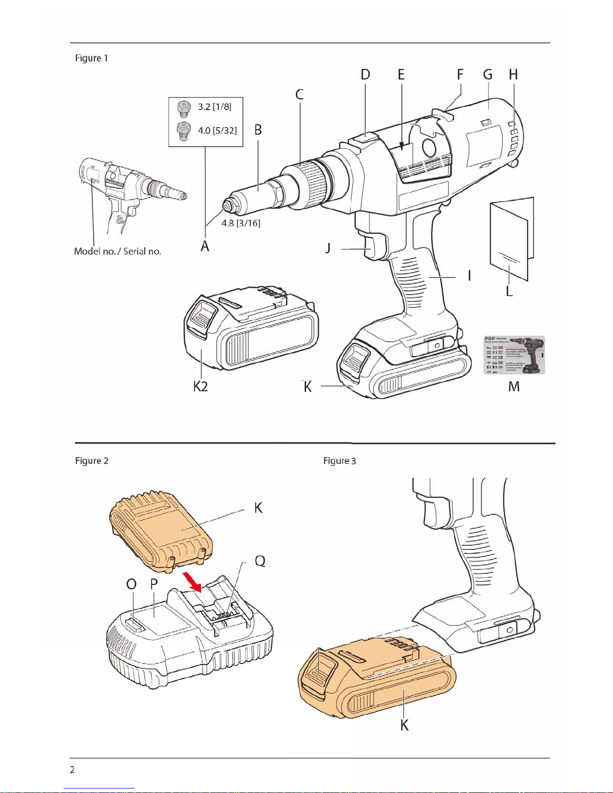
10. Charging Procedures ( g. 2)
1. Plug the charger into an appropriate outlet
before inserting the battery pack. (Refer to the
Charger Specifications)
2. Insert the battery pack (K) into the charger,
making sure the pack is fully seated in the
charger. The red (charging) light will blink
continuously indicating that the chargingprocess has started.
3. The completion of charge will be indicated by
the red light remaining ON continuously. The
pack is fully charged and may be used at this
time or left in the charger.
NOTE: To ensure maximum performance and life of
Li-Ion battery packs, charge the battery for aminimum
of 10 hours before first use.
11. Charging Process
Refer to the table below for the state of charge of the
battery pack.
State of charge
charging
–– –– –– ––
fully charged
–––––––––––––––––
hot/cold pack delay
–– • –– • –– • –– •
State of charge
x
problem pack or charger
• • • • • • • • • • • •
problem power line
•• •• •• •• •• ••
This charger will not charge afaulty battery pack.
The charger will indicate faulty battery by refusing to
light or by displaying problem pack or charger blink
pattern.
NOTE: This could also mean aproblem with acharger.
If the charger indicates aproblem, take the charger
and battery pack to be tested at an authorised service
centre.
12. Hot/Cold Pack Delay
When the charger detects abattery that is too hot
or too cold, it automatically starts ahot/cold pack
delay, suspending charging until the battery has
reached an appropriate temperature. The charger then
automatically switches to the pack charging mode.
This feature ensures maximum battery life. STANLEY
Engineered Fastening Li-Ion tools are designed with
an Electronic Protection System that will protect the
battery against overloading, overheating or deep
discharge. The tool will automatically turn off if the
Electronic Protection System engages. If this occurs,
place the Li-Ion battery on the charger until it is fully
charged. Acold battery pack will charge at about half
the rate of awarm battery pack. The battery pack
will charge at that slower rate throughout the entire
charging cycle and will not return to maximum charge
rate even if the battery warms.
13. Important Safety Instructions
for All Battery Packs
When ordering replacement battery packs, be sure to
include the catalogue number and voltage.
The battery pack is not fully charged out of the carton.
Before using the battery pack and charger, read the
safety instructions below and then follow the charging
procedures outlined.
READ ALL INSTRUCTIONS
• Do not charge or use the battery pack in
explosive atmospheres, such as in the presence
of flammable liquids, gases or dust. Inserting or
removing the battery pack from the charger may
ignite the dust or fumes.
• Never force the battery pack into charger. Do
not modify the battery pack in any way to fit
into anon-compatible charger as battery pack
may rupture causing serious personal injury.
• Charge the battery packs only in designated POP®
chargers.
Page 12

13
ENGLISH
• DO NOT splash or immerse in water or other liquids.
• Do not store or use the tool and battery pack in
locations where the temperature may reach or
exceed 40 °C (105 °F) (such as outside sheds or
metal buildings in summer).
• For best results, make sure the battery pack is fully
charged before use.
WARNING: Never attempt to open the
battery pack for any reason. If the battery
pack case is cracked or damaged, do not
insert it into the charger. Do not crush,
drop or damage battery pack. Do not use
abattery pack or charger that has received
asharp blow, been dropped, run over or
damaged in any way (e.g., pierced with
anail, hit with ahammer, stepped on).
Electric shock or electrocution may result.
Damaged battery packs should be returned
to the service centre for recycling.
CAUTION: When not in use, place tool on
its side on astable surface where it will
not cause atripping or falling hazard.
Some tools with large battery packs will
stand upright on the battery pack but may
be easily knocked over.
SPECIFIC SAFETY INSTRUCTIONS FOR LITHIUM
ION LIION
• Do not incinerate the battery pack even if it is
severely damaged or is completely worn out.
The battery pack can explode in afire. Toxic fumes
and materials are created when lithium ion battery
packs are burned.
• If battery contents come into contact with the
skin, immediately wash the area with mild soap
and water. If the battery liquid gets into the eye,
rinse water over the open eye for 15 minutes or until
irritation ceases. If medical attention is needed, the
battery electrolyte is composed of amixture of liquid
organic carbonates and lithium salts.
• Contents of opened battery cells may cause
respiratory irritation. Provide fresh air. If
symptoms persist, seek medical attention.
WARNING: Burn hazard. Battery liquid may
be flammable if exposed to spark or flame.
14. Battery Packs
BATTERY TYPE
The PB2500 operates on 18 volt battery pack. EBC180,
EBC181 & EBC183 battery packs may be used. Refer to
Technical Data for more information.
15. Storage Recommendations
1. The best storage place is one that is cool and
dry away from direct sunlight and excess heat
or cold. For optimum battery performance and
life, store battery packs at room temperature
when not in use.
2. For long storage, it is recommended to store
afully charged battery pack in acool, dry place
out of the charger for optimal results.
NOTE: Battery packs should not be stored completely
depleted of charge. The battery pack will need to be
recharged before use.
16. Labels on Charger and Battery
Pack
In addition to the pictographs used in this manual, the
labels on the charger and the battery pack show the
following pictographs.
Read instruction manual before use.
Battery charging.
Battery charged.
Hot/cold pack delay.
x
Problem pack or charger.
Problem power line.
Do not probe with conductive objects.
Do not charge damaged battery packs.
Use only with POP® battery packs. Others
may burst causing personal injury and
damage.
Do not expose to water.
Have defective cords replaced immediately.
Charge only between 4 °C and 40 °C.
Discard the battery pack with due care for
the environment.
Page 13

14
ENGLISH
Do not incinerate the battery pack.
Charges Li-Ion battery packs.
See Technical Data for charging time.
Only for indoor use.
17. Package contents
The package contains:
1 PB2500 tool with nose piece size ø 4.8 [3/16]
1 Charger 20 V max.
1 Battery 18 V Lithium Ion
1 Converter Plug for the UK (European tools only)
1 Bag with nose piece and matching jaw pusher
assembly extended tube size 4 (ø 3.2 [1/8])
1 Bag with nose piece and matching jaw pusher
assembly extended tube size 5 (ø 4.0 [5/32])
1 Instruction Manual
NOTE:
• Check for damage to the tool, parts or accessories
which may have occurred during transport.
• Take the time to thoroughly read and understand
this manual prior to operation.
18. Description ( g. 1)
Components Fig. 1 , 2 & 3
A. Nose Pieces
B. Nose housing
C. Nose housing nut
D. Collector lock
E. Collector shutter
F. Shutter guide sleeve
G. Motor housing
H. Exhaust vent
I. Handle
J. Switch
K. Battery Pack 1.5/2.0 Ah
K2. Battery Pack 3.0 Ah
L. Manual
M. USB Card with Manuals in EU languages
N. Charger lamp
O. Charger
Q. Battery charger connection
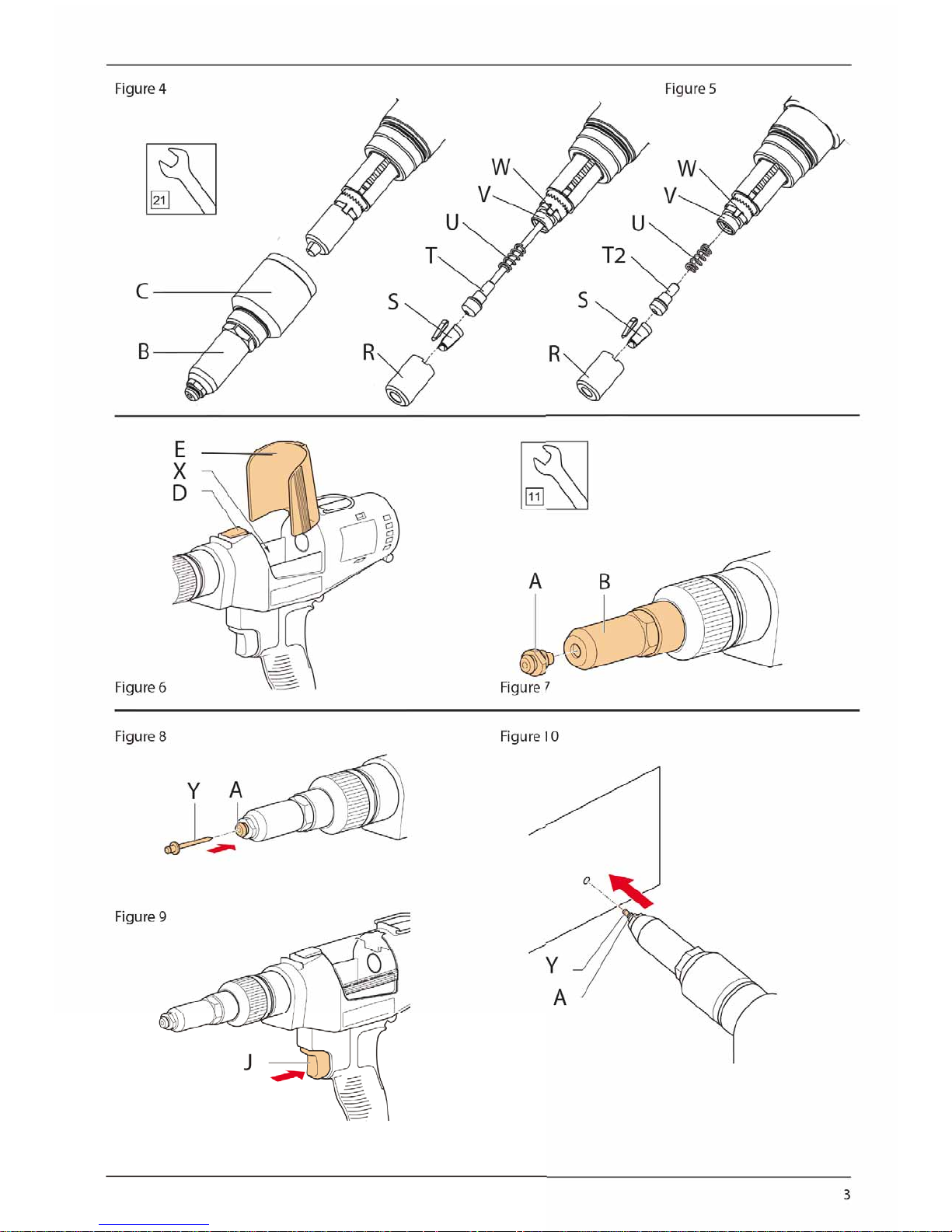
Components Fig. 4&5
R. Jaw guide
S. Jaws
T. Jaw pusher with extended tube size 4 (ø 3.2 [1/8])
or size 5 (ø 4.0 [5/32])
T2. Jaw pusher size 6 (ø 4.8 [3/16])
U. Spring
V. Pulling Head
W. Font Clutch (Jaw case lock)
X. Mandrel collector
Y. Blind rivet
19. INTENDED USE
This blind riveting power tool is designed for
professional blind rivet setting applications.
WARNING: Never modify the power tool or
any part of it. Damage or personal injury
could result.
DO NOT use under wet conditions or in presence of
flammable liquids or gases.
This blind riveter is aprofessional power tool.
DO NOT let children come into contact with the tool.
Supervision is required when inexperienced operators
use this tool.
• This product is not intended for use by persons
(including children) suffering from diminished
physical, sensory or mental abilities, or for lack
of experience and/or for want of knowledge
or skills unless they are supervised by aperson
responsible for their safety. Children should never
be left alone to play with this product.
20. Electrical Safety
The electric motor has been designed for one voltage
only. Always check that the battery pack voltage
corresponds to the voltage on the rating plate.
Also make sure that the voltage of your charger
corresponds to that of your mains.
Your POP® charger is double insulated in
accordance with EN 60335; therefore no
earth wire is required.
If the supply cord is damaged, it must be replaced by
aspecially prepared cord available through the POP®
service organisation.
21. Using an Extension Cable
An extension cord should not be used unless
absolutely necessary. Use an approved extension
cable suitable for the power input of your charger
Page 14

15
ENGLISH
(see technical data). The minimum conductor size is
1.5 mm²; the maximum length is 30 m. When using
acable reel, always unwind the cable completely.
22. ASSEMBLY & ADJUSTMENTS
WARNING: Prior to assembly and
adjustment, always remove the battery
pack. Always switch off the tool before
inserting or removing the battery pack.
WARNING: Use only POP® battery packs
and chargers.
23. Inserting and Removing the
Battery Pack from the Tool
( g.3)
NOTE: For best results, make sure your battery pack is
fully charged. The light will shut off without warning
when the battery is fully discharged.
TO INSTALL THE BATTERY PACK INTO THE
HANDLE
1. Align the battery pack (K) with the rails inside
the tool’shandle (fig. 3).
2. Slide it into the handle until the battery pack is
firmly seated in the tool and ensure that it does
not disengage.
TO REMOVE THE BATTERY PACK FROM TO THE
HANDLE
1. Press battery release button and firmly pull the
battery pack out of the tool handle.
2. Insert battery pack into the charger as
described in the charger section for this
manual.
24. Belt Hook and Bit Clip
WARNING: To reduce the risk of serious
personal injury, DO NOT suspend tool
overhead or suspend objects from the belt
hook. ONLY hang tool’sbelt hook from
awork belt.
WARNING: To reduce the risk of serious
personal injury, ensure the screw holding
the belt hook is secure.
IMPORTANT: When attaching or replacing the belt
hook or bit clip, use only the screw that is provided. Be
sure to securely tighten the screw. The belt hook and
bit clip can be attached to either side of the tool using
only the screw provided, to accommodate left- or
right-handed users. If the hook or bit clip is not desired
at all, it can be removed from the tool. To move belt
hook or bit clip, remove the screw that holds it in
place then reassemble on the opposite side. Be sure to
securely tighten the screw.
25. OPERATION
Instructions for Use
WARNING: Always observe the safety
instructions and applicable regulations.
WARNING: To reduce the risk of serious
personal injury, disconnect battery
pack before making any adjustments
or removing/installing attachments or
accessories.
26. Proper Hand Position
WARNING: To reduce the risk of serious
personal injury, ALWAYS use proper hand
position.
WARNING: To reduce the risk of serious
personal injury, ALWAYS hold securely in
anticipation of asudden reaction.
Proper hand position requires one hand on the main
handle fig. 1- (I).
27. Tool Setup & Mandrel Collection
WARNING: Before adjusting tool, always
remove the battery pack.
Opening and closing the mandrel collector (fig. 6)
• The mandrel collector is used to collect the rest
mandrel. To open the the mandrel collector (X),
slide the release button (D) towards the nose
housing nut (C) and raise the cover (E).
• To close the the mandrel collector (X), lower the
cover (E) until the release button (D) clicks into
place.
Mounting the nosepiece (fig. 7)
• Select the correct nosepiece for the rivet to be
installed Ref. Nose Piece chat.
• Tighten the nosepiece into the front sleeve. (B) by
turning it clockwise using 11 mm spanner.
Mounting the jaw pusher (fig. 5)
• Select the correct jaw pusher or jaw pusher
assembly (T, T2) that matches the Nose Piece
selected. Ref. Nose Piece chart.
• Insert small tube diameter into jaw pusher spring.
• Reassemble jaw set (S) and jaw case (R) onto jaw
case lock (W).
• Note: Avoid spanners to mount jaw case (R) onto
jaw case lock (W). Jaw case (R) manual tightening
is enough to lock jaw case (R) onto front clutch
(W).
Page 15

16
ENGLISH
X
D
E
28. Use
Place the rivet (fig. 8)
Place the blind rivet (Y) in the nose piece (A)
Position the tool (fig.10)
Switch operation (fig. 9)
• Pull and hold the switch (J) until the rivet is fully
set in the application.
• If you release the switch (J) before the end of the
setting stroke, the tool will immediately return
to its initial position. If the blind rivet (Y) has not
been set completely, repeat the previous steps.
• If the blind rivet (Y) has been set completely,
release the switch (J). The tool will return to its
initial position automatically. The mandrel is automatically dropped into the mandrel collector (X).
Reset function (fig. 9)
If the tool does not move to its initial position after
releasing the switch or stops during the setting
stroke, reset the tool to home by quickly pulling and
releasing the switch (J). If this does not work review
the Troubleshooting Guide.
29. Cleaning and Maintenance
WARNING: Before cleaning and
maintenance, always remove the battery
pack.
• Keep the ventilation openings free from dust and
dirt. If necessary, use asoft, moist cloth to remove
dust and dirt from the ventilation openings.
Emptying the mandrel collector
The mandrel collector must be emptied depending on
the size of the blind rivets used.
Nom. Rivet Dia. Approx. Capacity
2.4 mm [3/32“] 600
3.2 mm [1/8“] 360
4.0 mm [5/32“] 200
4.8 mm [3/16“] 150
• Open the mandrel collector (X).
• Hold the tool upside down above adustbin to
empty the mandrel collector (X).
• Close the mandrel collector (X).
30. Cleaning
WARNING: Blow dirt and dust out of the
main housing with dry air as often as dirt
is seen collecting in and around the air
vents. Wear approved eye protection and
approved dust mask when performing this
procedure.
WARNING: Never use solvents or other
harsh chemicals for cleaning the nonmetallic parts of the tool. These chemicals
may weaken the materials used in these
parts. Use acloth dampened only with
water and mild soap. Never let any liquid
get inside the tool; never immerse any part
of the tool into aliquid.
CHARGER CLEANING INSTRUCTIONS
WARNING: Shock hazard. Disconnect the
charger from the AC outlet before cleaning.
Dirt and grease may be removed from the
exterior of the charger using acloth or soft
non-metallic brush. Do not use water or any
cleaning solutions.
Cleaning the Nose Housing & Jaw Case (fig. 4 & 5)
• Loosen the nose housing nut (C). Remove the
nose housing (B).
• Press the jaw case lock (W) and loosen the jaw
guide (R). Release the jaw case lock (W).
• Remove the jaws (S) and the jaw pusher (T).
• Remove the spring (U).
• Clean the inside of the nose housing (B) using
adry cloth.
• Clean the clamping jaws (S) and the jaw pusher
(T) using adry cloth. If necessary, replace the jaws
(S) and the jaw pusher (T).
• Clean the pulling head (V) using adry cloth.
• Apply grease to the inside of the jaw guide (R)
where the jaws (S) make contact. AMolybdenum
Disulfide based grease is recommended.
• Mount the spring (U).
• Mount the jaw pusher (T) and the jaws (S).
• Press the jaw case lock (W) and tighten the jaw
guide (R). Release the jaw case lock (W).
• Mount the nose housing (B). Tighten the nose
housing nut (C).
31. Optional Accessories
WARNING: Since accessories, other than
those offered by POP® have not been tested
with this product, use of such accessories
with this tool could be hazardous. To reduce
the risk of injury, only POP® recommended
Page 16

17
ENGLISH
accessories should be used with this
product.
Consult your dealer for further information on the
appropriate accessories.
WARNING: To reduce the risk of serious
personal injury, disconnect battery
pack before making any adjustments
or removing/installing attachments or
accessories.
Maintenance Frequency
Item Frequency
Clean & lubricate Nose Housing &
Jaw Case
5,000 rivets
Clean & grease Ball Screw and
Thrust Bearing
50,000 rivets*
*Recommend contacting authorized service centre
32. Protecting the Environment
Separate collection. This product must not
be disposed of with normal household
waste.
Should you find one day that your POP® product
needs replacement, or if it is of no further use to you,
do not dispose of it with household waste. Make this
product available for separate collection.
Separate collection of used products and
packaging allows materials to be recycled
and used again. Re-use of recycled
materials helps prevent environmental
pollution and reduces the demand for raw
materials.
Local regulations may provide for separate collection
of electrical products from the household, at
municipal waste sites or by the retailer when you
purchase anew product.
You can check the location of your nearest authorised
repair agent by contacting your local POP® office at
the address indicated in this manual. Alternatively,
alist of authorised POP® repair agents and full details
of our after-sales service and contacts are available on
the Internet at:
www.StanleyEngineeredFastening.com.
33. Rechargeable Battery Pack
This long life battery pack must be recharged when it
fails to produce sufficient power on jobs which were
easily done before. At the end of its technical life,
discard it with due care for our environment:
• Run the battery pack down completely, then
remove it from the tool.
• Li-Ion cells are recyclable. Take them to your
dealer or alocal recycling station. The collected
battery packs will be recycled or disposed of
properly.
34. Protect your Investment!
Register Your Rivet Tool.
POP® RIVET TOOL WARRANTY
STANLEY Engineered Fastening warrants that all power
tools have been carefully manufactured and that they
will be free from defect in material and workmanship
under normal use and service for aperiod of one (1)
year. This warranty applies to the first time purchaser
of the tool for original use only.
Exclusions:
Normal wear and tear. Periodic maintenance, repair
and replacement parts due to normal wear and tear
are excluded from coverage.
Abuse & Misuse. Defect or damage that results
from improper operation, storage, misuse or abuse,
accident or neglect, such as physical damage are
excluded from coverage.
Unauthorized Service or Modification. Defects or
damages resulting from service, testing adjustment,
installation, maintenance, alteration or modification in
any way by anyone other than STANLEY Engineered
Fastening, or its authorized service centres, are
excluded from coverage.
All other warranties, whether expressed or implied,
including any warranties of merchantability or fitness
for purpose are hereby excluded.
Should this tool fail to meet the warranty, promptly
return the tool to our factory authorized service centre
location nearest you. For alist of POP Authorized
Service Centres in the US or Canada, contact us at our
toll free number (877)364 2781.
Outside the US and Canada, visit our website
www.StanleyEnigineeredFastening.com to find
your nearest STANLEY Engineered Fastening location.
STANLEY Engineered Fastening will then replace, free
of charge, any part or parts found by us to be defective
due to faulty material or workmanship, and return the
tool prepaid. This represents our sole obligation under
this warranty. In no event shall STANLEY Engineered
Fastening be liable for any consequential or special
damages arising out of the purchase or use of this
tool.
To register your warranty online, visit us
http://www.stanleyengineeredfastening.com/
poppowertools/warranty-card. Thank you for choosing
an STANLEY Engineered Fastening’s POP® Brand tool.
Page 17

18
ENGLISH
35. USB with manual in other
European languages.
Operating instructions are available on this USB in
other European languages. If for whatever reason
you cannot read the USB or do not have the means
to open the USB, please contact and we will send you
apaper copy in the language requested.
Do not use tool before first having read the complete
operating instructions!
36. Parts List
NO Part
Number
Description
C 1 TP124-542 Nosepiece Assembly, 4.8 mm [3/16”] size
C 2 TP124-503 O-Ring
3 (See item 1) Nosepiece
C 4 TP094-552 Steel Ball
C 9 PRS2500-01 Jaw Guide
C 10 71210-15001 Jaws - One Set (3)
C 11 TP154-500 Jaw Pusher Assembly, 4.8 mm [3/16"] size
12 (See item 11) Jaw Pusher
13 TP124-501 O Ring
C 14 TP114-652 Jaw Pusher Spring
C 15 TP124-505 O Ring
16 TP113-610 Mast Housing
17 TP123-555 Pulling Head Assembly
18 TP113-606 Spindle Clutch
19 TP114-666 Spindle Clutch Spring
20 TP114-637 Tail Guide
21 TP123-553 Gear Housing Assembly
29 TP123-551 SA Second Shaft
30 TP123-550 SA Planetary Shaft
31 N112877 Gear, Ring
32 TP124-511 O Ring
33 TP122-535 SA Motor and Module, PB2500
34 TP114-628 Pipe Bridge
35 TP114-665 Mandrel Plate
36 TP114-676 Shutter Guide Sleeve
Page 18

19
ENGLISH
NO Part
Number
Description
37 TP124-677 Collector Shutter Lock Spring
38 TP124-532 Collector Lock
39 TP123-531 Collector Shutter
g40
TP130-606 Housing Assembly PB2500 NA
TP122-631 Housing Assembly PB2500 QW, GW
TP122-662 Housing Assembly PB2500 XE
41 TP124-513 Cross Recessed Pan Head Tapping Screw
42 TP124-514 Cross Recessed Pan Head Tapping Screw
C 50 TP124-540 Nosepiece Assembly, 3.2 mm
[1/8”] size
C 51 TP124-524 O Ring
52 (See item 50) Nosepiece
C 53 TP124-541 Nosepiece Assembly, 4.0 mm
[5/32”] size
54
(see item 53)
Nosepiece
C 55 TP154-502 Jaw Pusher Assembly, 3.2 mm
[1/8”] size
56
(see item 55)
Jaw Pusher
C 57 TP154-505 Jaw Pusher Assembly, 4.0 mm [5/32”] size
58
(see item 57)
Jaw Pusher
C
g59
EBC183-( )
2.0 Ah Battery, NA, QW, XE (Use QW with model no. PB2500-GB)
g60
EBC-101NA Battery Charger, PB2500 NA
EBC105-( )
Battery Charger, GB,QW,XE (Ref. PB2500-( ) model no.)
61 SA Kit Box
62
TP133-570
SA Nose Housing Assembly
C
*g
EBC-181( ) 1.5 Ah Battery, NA, QW, XE (use QW with model no. PG2500 GB)
C
*g
EBC-180( ) 3.0 Ah Battery, NA, QW, XE (use QW with model no. PG2500 GB)
*g
PNT132-600 Hook, PB2500
"C" Marked Parts are Consumable Not Warranted
* Marked Parts are Optional, Not o ered as Standard Equipment
Shaded Parts are Recommended for Stainless Steel Rivets
g
Select Part Number based on Tool Model Number: PB2500-NA, QW, GB, XE
Page 19

20
ENGLISH
37. Exploded View Diagram
59
50
1
11
21
53
3
9
10
12
13
14
15
16
18
19
20
17
22
24
25
26
27
28
40
34
39
38
37
40 41 42 42
41
41
41
41
41
35
30
31
32
34
36
33
2
4
62
23
29
10. Exploded View
55
4
51
52
54
51
4
13
58
61
57
13
56
60
Page 20

21
ENGLISH
38. Nosepiece, Jaw and Jawpusher chart
NOSEPIECE SELECTION CHART
Size Rivet Type
Material (Body/Mandrel)
All Mat’ls Al/Al Al/St, Al/SS
NiCu/St, NiCu/SSSt/St, SS/St,
SS/SS
2.4 mm [3/32”] Open End TP124-539 ----
3.0 mm PT Rivet TP124-540* ----
3.2 mm [1/8”]
Avex®/Avibulb® TP124-540* ----
Closed End - TP124-615 TP124-544 TP124-540* TP124-540*
HR/HT Rivet - TP124-541* TP124-540* - TP124-541*
Open End/LS Rivet TP124-540* ----
Stavex®/Avinox® TP124-541* ----
4.0 mm [5/32”]
Avex® TP124-541* ----
Avinox®/Avibulb® TP124-542* ----
Closed End TP124-545 ----
HR/HT Rivet - TP124-542* TP124-541* - TP124-542*
Open End/Bulbex®/TL TP124-541* ----
Stavex® TP124-542* ----
4.8 mm [3/16”]
Avex® TP124-542* ----
Avinox®/Avibulb® TP124-543 ----
Bulbex®/TL/Klamp-Tite®** TP124-542* ----
Closed End - TP124-546 TP124-546 TP124-542* TP124-542*
HR/HT Rivet - TP124-543 TP124-542* - TP124-543
Interlock® TP124-542* ----
Open End TP124-542* ----
Stavex® TP124-542* ----
* Included with the standard tool kit
** Klamp-Tite® KTR series requires a Special Nosepiece, contact Applications Engineering
JAW & JAW PUSHER SELECTION CHART
Size Rivet Type
Jaw Jaw Pusher
Stainless Mandrel Stainless Mandrel
2.4 mm [3/32”] Open End PRG540-46B - TP124-547 -
3.0 mm PT Rivet 71210-15001 - TP154-502 -
3.2 mm [1/8”]
Avex®
71210-15001
1)
PRG540-46B
TP154-502
TP124-638
Avinox®/Avibulb® TP154-502
Closed End TP154-502
HR/HT Rivet TP154-505
2)
Open End/LS Rivet TP154-502
Stavex® TP154-505
4.0 mm [5/32”]
Avex®
71210-15001 PRG540-46B
TP154-505
TP124-618
Avinox®/Avibulb® TP154-500
Closed End TP154-505
HR/HT Rivet TP154-500
3)
Open End/Bulbex®/TL TP154-505
Stavex® TP154-500
4.8 mm [3/16”]
Avex®/Stavex®
71210-15001 PRL650-01 TP154-500 TP124-620
Avibulb®/Avinox®
Bulbex®/Klamp-Tite®
LS Rivet/TL Rivet
Open End/Closed End
HR/HT/Interlock®
1) Recommend 71200-15001 Jaws for 3.2 mm [1/8”] Closed End with Steel Mandrel
2) Use TP154-502 Jaw Pusher with 3.2 mm [1/8”] Al/St HR Rivet
3) Use TP154-505 Jaw Pusher with 4.0 mm [5/32”] Al/St HR Rivet
Page 21

22
ENGLISH
39. Troubleshooting guide
Symptom Cause Remedy
Tool stops before rivet is fully set Setting load of rivet is beyond tool
capacity.
Reset tool to home, remove rivet &
use appropriate tool to set rivet.
Improper nosepiece selection. Reset tool to home, remove rivet &
fit proper nose piece.
Battery pack has reached operating
temperature limit through
continuous use or defect.
Remove battery & allow to cool.
Mount battery and reset tool to
home.
Tool does not return to initial
position when switch is released.
Electrical malfunction. Remove battery, wait 5 seconds and
reinsert. Reset tool to home.
Tool does not operate when switch
is pressed.
Battery is not fully seated Remove battery and re-insert. Reset
tool to home.
Battery is not fully charged Charge battery
Battery pack has reached operating
temperature limit through
continuous use or defect.
Remove battery & allow to cool.
Mount battery and reset tool to
home.
Battery is defective Replace battery
*Reset tool to home: quickly pull & release the switch
Page 22

23
ENGLISH
E
X
D
A
B
Mount the nose piece (A).
Y
A
Place the blind rivet (Y) in the nose
piece (A).
Position the tool.
Y
A
Press and hold the switch (J) until
blind rivet is fully set.
J
Close the lid (E) of the mandrel
collector (X).
Page 23

24
ENGLISH
Page 24

 Loading...