

Page 1

Page 2
1
Page 3
2
Page 4
3
Page 5
4
Page 6

5
Page 7
1.1 GENERAL SAFETY
Do not use outside the design intent of Placing STANLEY Engineered Fastening Blind Fasteners.
Use only parts, fasteners, and accessories recommended by the manufacturer.
Use Power Tool only with specifically designated battery packs.
6
Page 8

1.2 POWER TOOL USE AND CARE
The tool must be maintained in a safe working condition at all times and examined at regular intervals for damag e and
function by trained personnel. Any dismantling procedure will be undertaken only by trained personnel. Do not dismantle
this tool without prior reference to the maintenance instructions.
Do not modify the tool in any way. Any modification to the tool is undertaken by the customer and will be the customer’s
entire responsibility and void any applicable warranties.
Disconnect the battery from the tool before performing any maintenance, attempting to adjust, fit or remove a nose
assembly.
Prior to use, check for misalignment or binding of moving parts, breakage of parts, and any other condition that affects the
tool’s operation. If damaged, have the tool serviced before using. Remove any adjusting key or wrench before use.
Prior to use, inspect battery for damage. Do not drop battery. A sharp impact may cause internal damage and lead to
premature battery failure.
Keep work area clean and well lit.
Dress properly. Do not wear loose clothing or jewelry. Keep your hair, clothing and gloves away from moving parts. Loose
clothes, jewelry or long hair can be caught in moving parts.
Adopt a firm footing or a stable position before operating the tool.
Operators and others in work area must wear ANSI Z87.1 CAN/CSA Z94.3 approved safety glasses with side shields. Always
wear safety glasses and ear protection during operation.
Adequate clearance is required for the tool operator’s hands before proceeding.
Do not operate a tool that is directed towards any person(s).
DO NOT operate tool with the nose housing removed.
Do not operate the tool or the charger in an explosive atmosphere or environment allowing exposure to combustible fluids
or gasses.
Do not operate the tool or the charger in an environment allowing exposure to moisture or rain to avoid risk of electric
shock.
Do not abuse the tool by dropping or using it as a hammer.
Keep dirt and foreign matter out of the air vents of the tool as this will cause the tool to malfunction.
Keep tool handles dry, clean, and free from oil and grease.
When carrying the tool from place to place keep hands away from the trigger to avoid inadvertent activation.
Never leave operating tool unattended.
Disconnect battery when tool is not in use.
1.3 IMPORTANT SAFETY INSTRUCTIONS FOR ALL BATTERY CHARGERS
SAVE THESE INSTRUCTIONS: This manual contains important safety and operating instructions for compatible battery chargers
(refer to Technical Data).
Before using charger, read all instructions and cautionary markings on charger, battery pack, and product using battery
pack.
WARNING: Shock hazard. Do not allow any liquid to get inside charger. Electric shock may result.
WARNING: We recommend the use of a residual current device with a residual current rating of 30mA or less.
CAUTION: Burn hazard. To reduce the risk of injury, charge only DEWALT/POP-Avdel rechargeable batteries. Other types of
batteries may burst causing personal injury and damage.
7
Page 9

CAUTION: Children should be supervised to ensure that they do not play with the appliance.
NOTICE: Under certain conditions, with the charger plugged into the power supply, the exposed charging contacts inside the
charger can be shorted by foreign material. Foreign materials of a conductive nature such as, but not limited to, steel wool,
aluminium foil or any build-up of metallic particles should be kept away from charger cavities. Always unplug the charger from
the power supply when there is no battery pack in the cavity. Unplug charger before attempting to clean
DO NOT attempt to charge the battery pack with any chargers other than the ones in this manual. The charger and battery
pack are specifically designed to work together.
These chargers are not intended for any uses other than charging DEWALT/POP-Avdel rechargeable batteries. Any other
uses may result in risk of fire, electric shock or electrocution.
Do not expose charger to rain or snow.
Pull by plug rather than cord when disconnecting charger. This will reduce risk of damage to electric plug and cord.
Make sure that cord is located so that it will not be stepped on, tripped over, or otherwise subjected to damage or stress.
Do not use an extension cord unless it is absolutely necessary. Use of improper extension cord could result in risk of fire,
electric shock, or electrocution.
Do not place any object on top of charger or place the charger on a soft surface that might block the ventilation slots and
result in excessive internal heat. Place the charger in a position away from any heat source. The charger is ventilated
through slots in the top and the bottom of the housing.
Do not operate charger with damaged cord or plug—have them replaced immediately.
Do not operate charger if it has received a sharp blow, been dropped, or otherwise damaged in any way. Take it to an
authorised service centre.
Do not disassemble charger; take it to an authorised service centre when service or repair is required. Incorrect reassembly
may result in a risk of electric shock, electrocution or fire.
Disconnect the charger from the outlet before attempting any cleaning. This will reduce the risk of electric shock. Removing
the battery pack will not reduce this risk.
NEVER attempt to connect two chargers together.
The charger is designed to operate on standard household electrical power (refer to charger specifications). Do not attempt
to use it on any other voltage. This does not apply to the vehicular charger.
1.4 IMPORTANT SAFETY INSTRUCTIONS FOR ALL BATTERY PACKS
When ordering replacement battery packs, be sure to include catalog number and voltage.
The battery pack is not fully charged out of the carton. Before using the battery pack and charger, read the safety instructions
below. Then follow charging procedures outlined.
READ ALL INSTRUCTIONS
Do not charge or use battery in explosive atmospheres, such as in the presence of flammable liquids, gases or dust. Inserting
or removing the battery from the charger may ignite the dust or fumes.
Never force battery pack into charger. Do not modify battery pack in any way to fit into a non-compatible charger as battery
pack may rupture causing serious personal injury.
Charge the battery packs only in DEWALT/POP-Avdel chargers.
DO NOT splash or immerse in water or other liquids.
Do not store or use the tool and battery pack in locations where the temperature may reach or exceed 40 ˚C (104 ˚F) (such as
outside sheds or metal buildings in summer).
When battery pack is not in use, keep it away from other metal objects like paper clips, coins, keys, nails, screws or other
small metal objects that can make a connection from one terminal to another.
Do not discard batteries into water.
8
Page 10
WARNING: Never attempt to open the battery pack for any reason. If battery pack case is cracked or damaged, do not
insert into charger. Do not crush, drop or damage battery pack. Do not use a battery pack or charger that has receiv ed a sharp
blow, been dropped, run over or damaged in any way (i.e., pierced with a nail, hit with a hammer, stepped on). Electric shock or
electrocution may result. Damaged battery packs should be returned to service centre for recycling.
WARNING: Fire hazard. Do not store or carry the battery pack so that metal objects can contact exposed battery
terminals. When transporting individual battery packs, make sure that the battery terminals are protected and well insulated
from materials that could contact them and cause a short circuit.
CAUTION: When not in use, place tool on its side on a stable surface where it will not cause a tripping or falling hazard.
Some tools with large battery packs will stand upright on the battery pack but may be easily knocked over.
1.5 SPECIFIC SAFETY INSTRUCTIONS FOR LITHIUM-ION (LI-ION)
1. Do not incinerate the battery pack even if it is severely damaged or is completely worn out. The battery pack can explode
in a fire. Toxic fumes and materials are created when lithium-ion battery packs are burned.
2. If battery contents come into contact with the skin, immediately wash area with mild soap and water. If battery liquid
gets into the eye, rinse water over the open eye for 15 minutes or until irritation ceases. If medical attention is needed, the
battery electrolyte is composed of a mixture of liquid organic carbonates and lithium salts.
3. Contents of opened battery cells may cause respiratory irritation. Provide fresh air. If symptoms persists, seek medical
attention.
WARNING: Burn hazard. Battery liquid may be flammable if exposed to spark or flame.
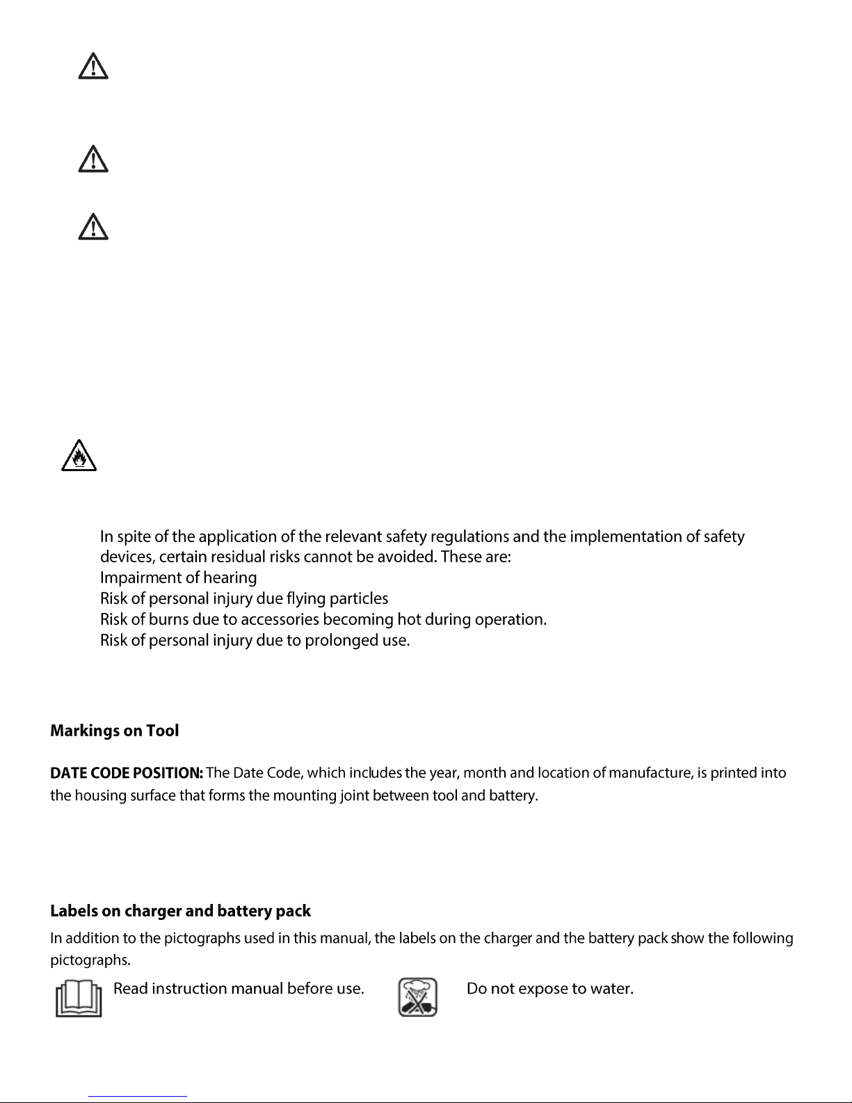
1.6 RESIDUAL RISKS
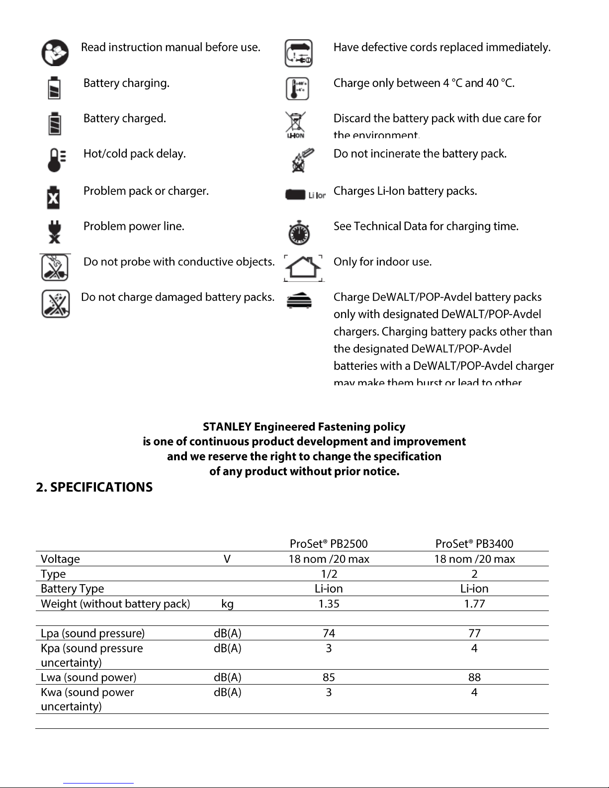
1.7 LABELS AND ICONS
9
Page 11
2.1 TECHNICAL DATA
2.1.1.
10
Page 12
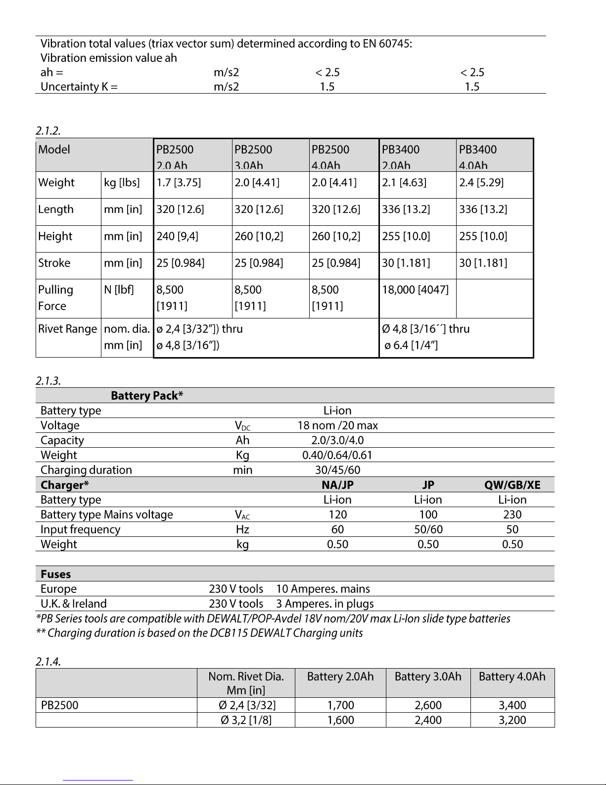
11
Page 13
Rivet Type
PLACING CAPACITY
PB2500
PB3400
2.0
mm
2.4mm
[3/32´´]
3.0
mm
3.2mm
[1/8´´]
4.0mm
[5/32´´]
4.8mm
[3/16´´]
5.0/6.0
/7.0
mm
4.8mm
[3/16´´]
6.0 mm
6.4mm
[1/4´´]
8.0/9.0
mm
OPEN END
CLOSED END
AVEX/
STAVEX
● ● ● ● ● ●
AVINOX/
AVIBULB
● ● ● ● ● ●
HR/HT
INTERLOCK
KLAMP-TITE/
KTR
● ● ●
BULBEX/LS/TL
MONOBOLT
MULTI-GRIP
PULL-THRU (PT)
Q RIVET
T LOK
T-RIVET
AVSEAL II
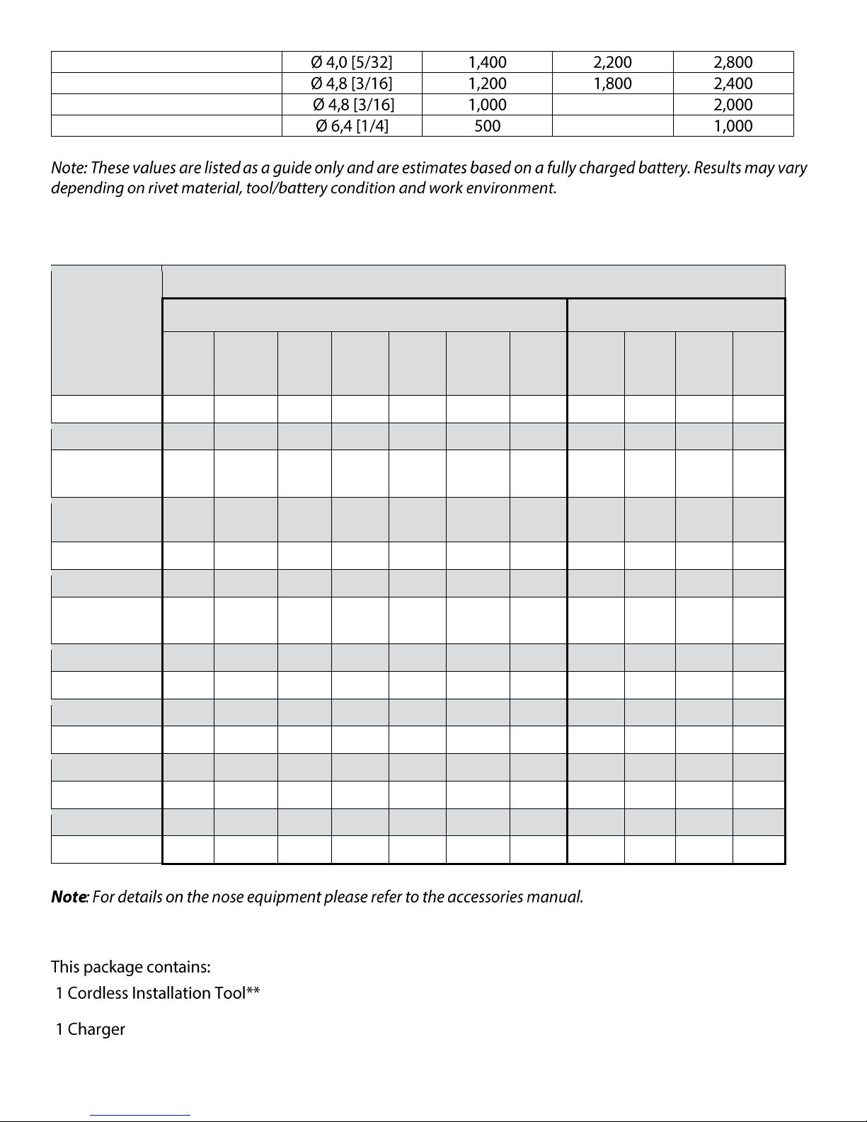
2.2 PLACING SPECIFICATIONS
2.3 PACKAGE CONTENTS
12
Page 14
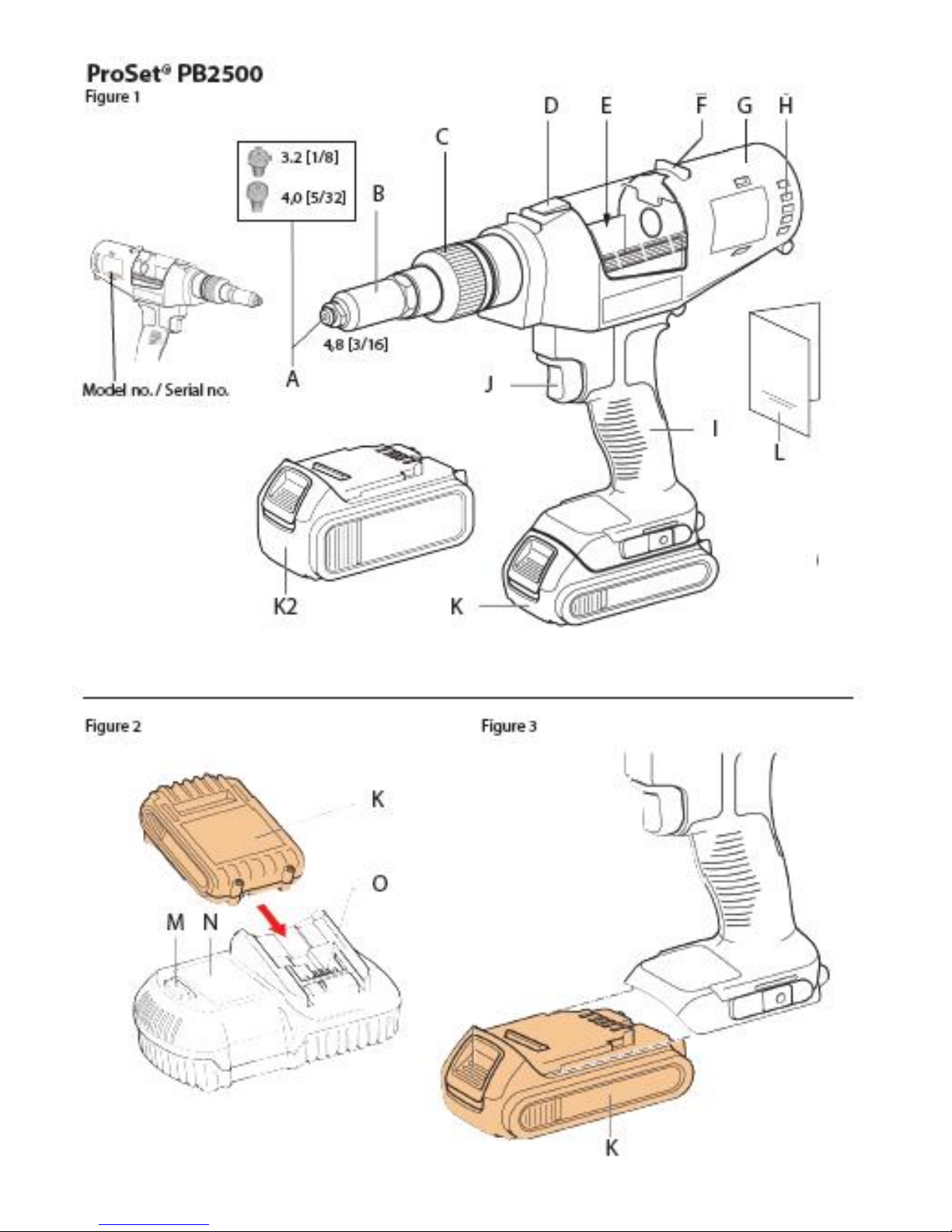
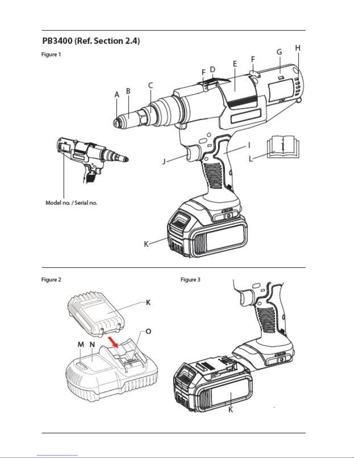
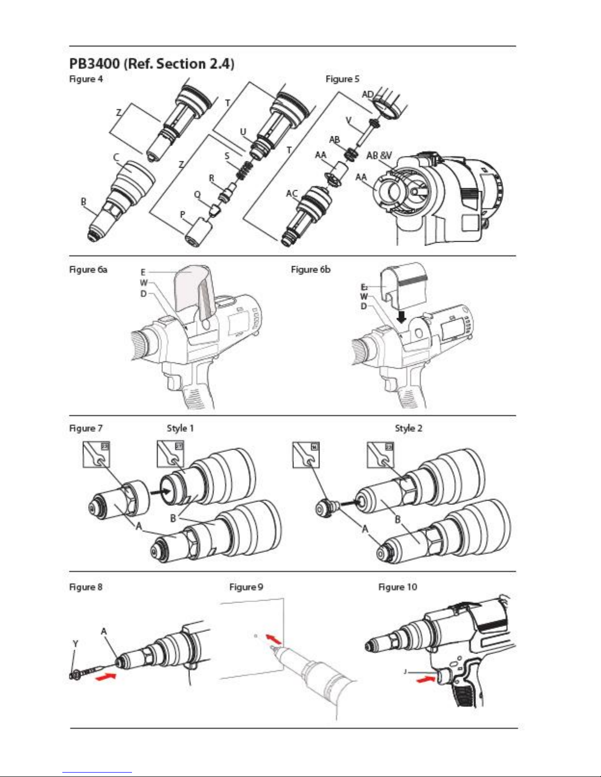
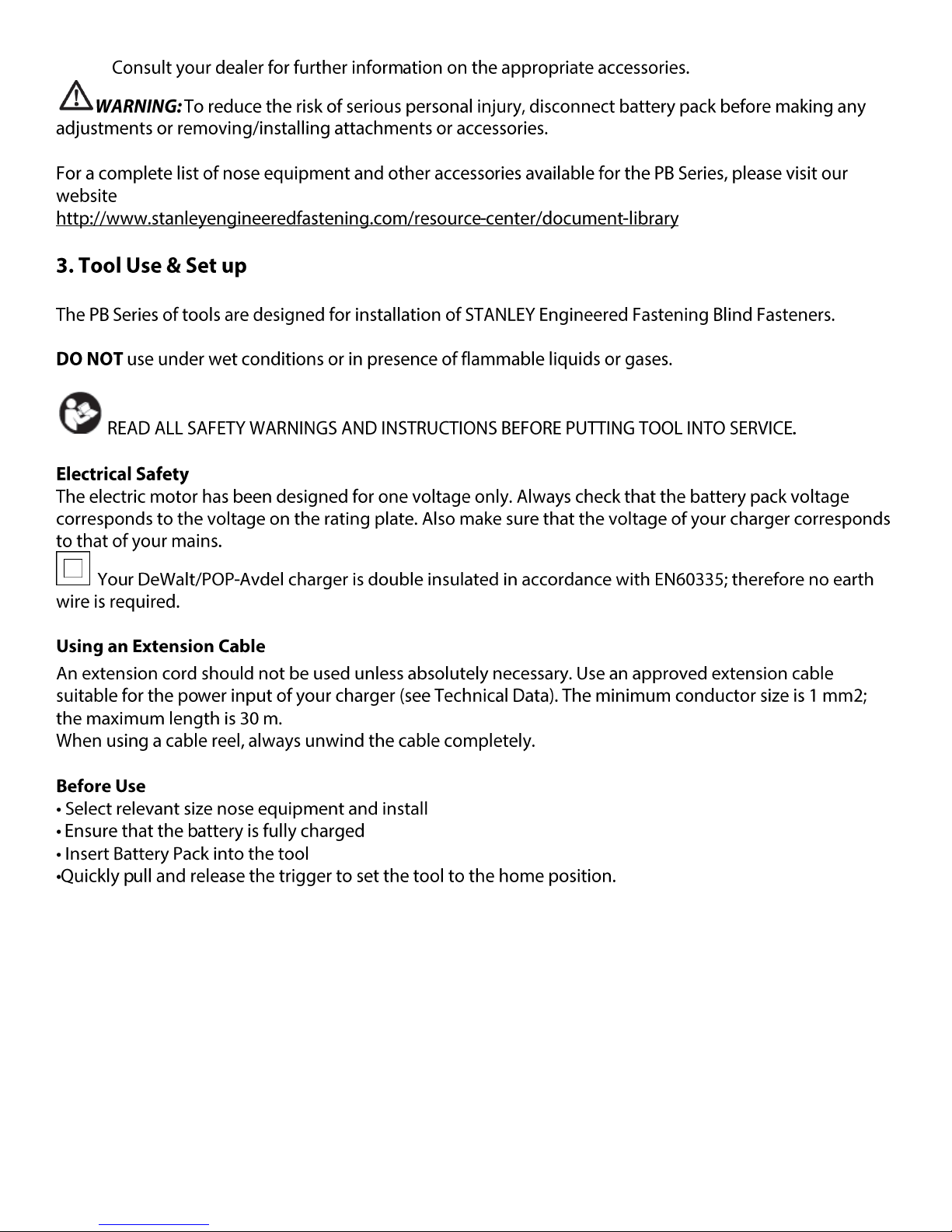
2.4 MAIN COMPONENTS LIST (for complete tool explosion and Bill of Material please see service manual)
ProSet® PB2500 drawing can be found inside the front cover
ProSet® BB3400 drawing can be found inside the back cover
2.5 OPTIONAL ACCESSORIES
13
Page 15
14
Page 16
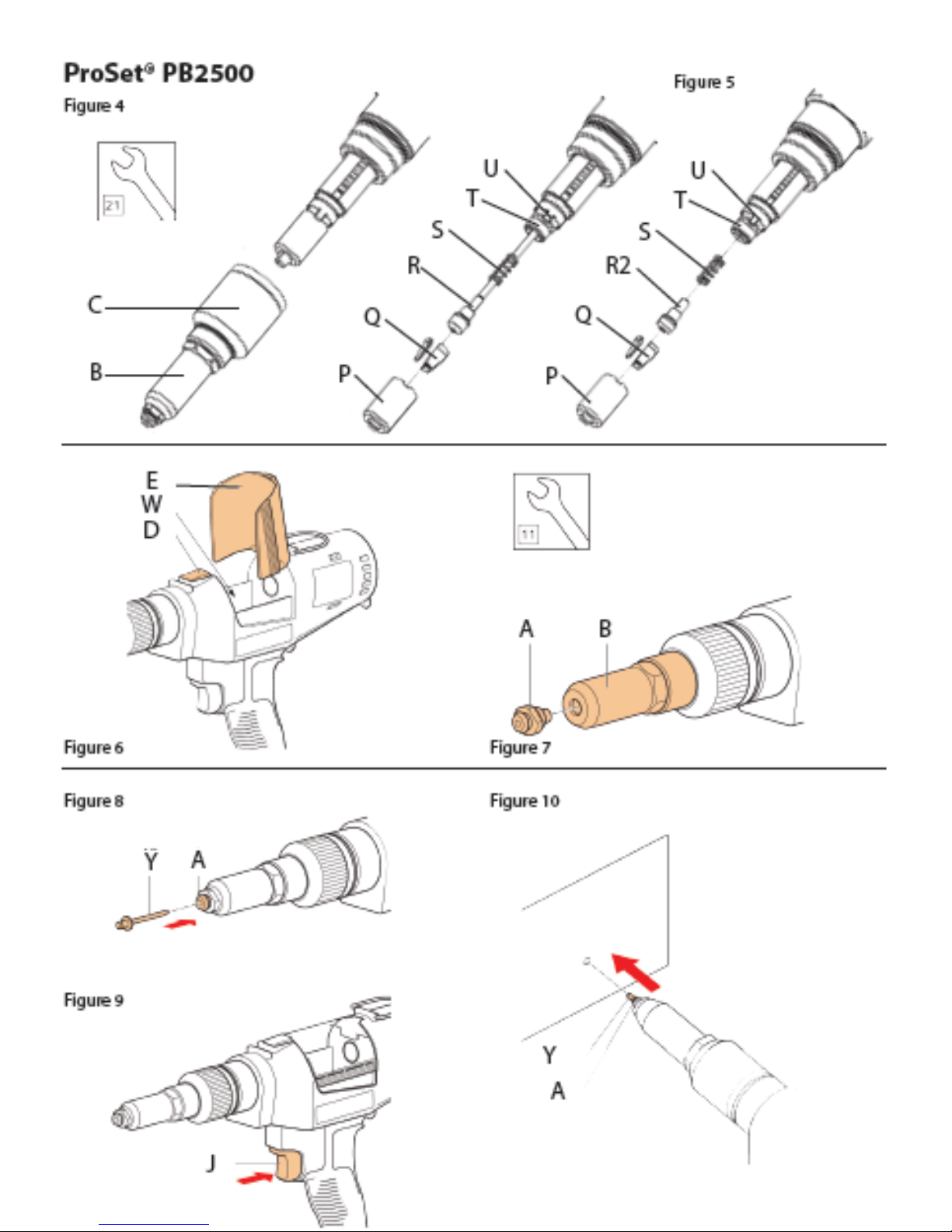
4.1. NOSE EQUIPMENT
4.2. CHARGERS
15
Page 17

4.3 BATTERY PACKS
16
Page 18

17
Page 19

18
Page 20

19
Page 21

20
Page 22

7. Motor and Module Assembly and SA Planetary Carrier
MOTOR AND MODULE ASSEMBLY
TRM00127
1
SA MOTOR AND MODULE, PB3400
TP152-519
1
RING GEAR
N112877
1
O RING
TP124-511
1
SA PLANETARY CARRIER
TP143-625
1
O-ring
SA Motor and Module
Ring Gear
SA Planetary Carrier
Ring Gear
Motor housing
BOM for Motor and Module Assembly and SA Planetary Carrier
Fit the Ring Gear on to the Motor housing in
the SA Motor and Module assembly
21
Page 23

Ring Gear
Motor housing
O-ring
O-ring
Apply grease
Ring Gear
Motor Pinion
Boss on Ring gear
Top side
Set the O-ring onto the groove between the
Motor housing and Ring Gear
Align the middle boss on the Ring Gear to the
top side of the Motor Housing
Apply grease to the Ring Gear and Motor
Pinion.
Grease recommended: HIWIN G01
22
Page 24

Insert the SA Planetary Carrier into the Ring
Memo
Gear.
23
Page 25

9. Main Unit Assembly
MAIN UNIT ASSEMBLY
NA
1
MOTOR AND MODULE ASSEMBLY AND SA
PLANETARY CARRIER
NA
1
SA HOUSINGS
TP142-628
1
FRONT UNIT ASSEMBLY
TP143-683
1
SA SECOND SHAFT
TP143-620
1
MANDREL PLATE
TP144-681
1
SHUTTER GUIDE SLEEVE
TP114-676
1
COLLECTOR SHUTTER LOCK SPRING
TP114-677
1
COLLECTOR LOCK
TP124-532
1
COLLECTOR SHUTTER
TP143-627
1
CROSS RECESSED PAN HEAD TAPPING SCREW
TP124-513
14
3x16L
CROSS RECESSED PAN HEAD TAPPING SCREW
TP124-514
2
3x20L
Collector Lock
Shutter Guide Sleeve
Collector Shutter
Lock Spring
Front Unit Assembly
Mandrel Plate
SA Second
Shaft
Collector Shutter
Cross Recessed Pan
Head Tapping Screw
SA Housings
Motor and Module Assembly
SA Planetary Carrier
BOM for Main Unit Assembly
24
Page 26

Mandrel Plate
Upper side
Ring Gear is
fitted correctly
Housing (Left side)
Wires are fitted inside
this harness
Wire harnesses
are set correctly
Boss is set in this slit
Boss is set in this slit
Battery terminal is set correctly
Set the Mandrel Plate into the groove of the
SA Housing (left side).
Set the Motor and Module Assembly, with the SA Planetary Carrier, in to the SA
Housing (left side).
Check the following pictures to ensure a clean fit inside the SA Housing.
25
Page 27

Collector Lock
Collector Shutter Lock Spring
SA Second Shaft
Gear Housing
SA Second shaft
Front Unit Assembly
Pipe Bridge
Set the Collector Shutter Lock Spring on the
Boss of the Collector Lock.
Insert the SA Second Shaft into the hole on the
Gear Housing for the Front Unit Assembly.
Fit the Front Unit Assembly with the SA Second
Shaft in to the SA Housing (left side).
Be careful on the position of the Pipe Bridge.
26
Page 28

Collector Lock with spring
Collector Lock with spring
SA Housing (right side)
Electric Screw Driver etc.
Tapping Screw (TP124-514, 3-20)
For Collector Lock
Fit the Collector Lock, with spring, on to the SA
Housing (left side).
Be careful that the Spring does not drop off.
Place the SA Housing (right side) over the SA
Housing (left side).
Be careful that the Spring does not drop off.
Tighten the Cross Recessed Tapping Screw
(TP124-514, 3-20) in to the position of the
Collector Lock by using a screw driver (electric
recommended).
Set Torque: 0.95Nm
27
Page 29

Places for Tapping Screw (TP124-513, 3-16)
Collector Shutter
Shutter Guide Sleeve
Collector Shutter
Shutter Guide Sleeve
Tighten the Cross Recessed Tapping Screws
(TP124-513 3-16) to the 14 places shown in
the adjacent picture by using a screw driver
(electric recommended).
Set Torque: 0.95Nm
Insert Shutter Guide Sleeve into the hole of the
Collector Shutter.
Be careful that the Shutter Guide Sleeve does
not take off the hole.
Set the Collector Shutter, with the Shutter
Guide Sleeve, on to the SA Housing.
Be careful that the Shutter Guide Sleeve does
not take off the hole.
28
Page 30

Tapping Screw (TP124-514, 3-20)
Electric Screw Driver etc.
Memo
Tighten the Cross Recessed Tapping Screw
(TP124-514, 3-20) by using a screw driver
(electric recommended).
Set Torque: 0.95Nm
29
Page 31

10. Jaws, Jaw Guide, Jaw Pusher and Jaw Pusher Spring
JAWS
NA
1 JAW GUIDE
TP142-628
1 SA JAW PUSHER, 8
TP143-683
1
JP, NA, XE, XD
SA JAW PUSHER, 8K
TP144-655
1
QW, GB
SA JAW PUSHER, 6
TRM00157
1
OPTION
JAW PUSHER SPRING
TP143-620
1
SA Jaw Pusher, 8
Jaws
Jaw Pusher Spring
Jaw Guide
SA Jaw Pusher,8K
SA Jaw Pusher, 6
Apply grease
Jaw Guide
Grease
BOM for Jaws, Jaw Guide, SA Jaw pusher and Jaw Pusher Spring
Apply grease to the inside of the Jaw Guide.
Grease recommended:
Molybdenum disulfide grease
30
Page 32

Jaw Guide
Jaws
Jaw Guide
Jaws
Jaw Pusher Spring
Pulling Head
Put the Jaws into the Jaw Guide (as shown) so
that the teeth are on the inside.
After inserting the Jaws, check that they are
set correctly.
Put the Jaw Pusher Spring into the Pulling
Head.
31
Page 33

Jaw Pusher Spring
SA Jaw Pusher
Jaw Guide
Jaw Case Lock
Pulling Head
Jaw Case Lock
Jaw Guide
Lock
Put the SA Jaw Pusher through the Jaw Pusher
Spring.
Tighten the Jaw Guide, with Jaws, to the
Pulling Head, with pulling Jaw Case Lock, by
hand until it stops.
Turn back a little until the rotation is locked by
the boss of the Jaw Case Lock.
32
Page 34

Battery
Set a battery on to the tool to check the
operation.
Check the tool operates correctly by pulling
and releasing the trigger .
Check for:
Pulling operation
Return operation
Reset operation
Full stroke → Stroke end clutch operation →
Return to home position→Front end clutch
operation
Remove the battery after checking.
33
Page 35

4. SA Nose Housing and SA Nose Piece
SA NOSE HOUSING
TP143-594
1
SA NOSE HOUSING
TP143-643
1 SA NOSEPIECE
Many
1
A type
SA NOSEPIECE
Many
1
B type
SCREW WRENCH
TP144-682
1
Accessory
SA Nosepiece A type
SA Nose Housing(TP143-594)
SA Nosepiece B type
SA Nose Housing(TP143-643)
SA Nosepiece A type
SA Nose Housing(TP143-594)
Screw Wrench
BOM for SA Nose Housing and SA Nosepiece
Special tool for Assembling
Insert the SA Nosepiece A type on to the SA
Nose Housing (TP143-594) and screw on by
hand.
34
Page 36

SA Nosepiece A type
SA Nose Housing(TP143-594)
Spanner 14mm
Spanner 23mm
SA Nosepiece B type
SA Nose Housing(TP143-643)
SA Nosepiece B type
SA Nose Housing(TP143-643)
Spanner 23mm
Spanner 27mm
Nose Hosuing Nut
Tighten up the SA Nosepiece A type securely
with spanners (see adjacent picture)
Width across flats: 14mm and 23mm
Insert the SA Nosepiece B type on to SA the
Nose Housing (TP143-643) and screw on by
hand.
Tighten up the SA Nosepiece B type securely
by using the Screw wrench provided in the kit
box and another spanner (see adjacent
picture).
Width across flats: 27mm and 23mm
Apply grease to the inside of Nose Housing Nut
(see adjacent picture).
35
Page 37

Apply grease
SA Nose Hosuing
Mast Hosuing
SA Nose Hosuing
Mast Hosuing
Insert the SA Nose Housing on to the Mast
Housing of the tool.
Tighten the SA Nose Housing on to the thread
of the Mast Housing by hand.
36
Page 38

11. Operation Test and Appearance check
Memo
Operation Check
Set 30 rivets of 8 size steel to check:
The tool does not slip
Rivet setting is done in one stroke
There is no protruding mandrels
There is no abnormal noise
The next rivet introduced to the front of the
tool is inserted smoothly.
The jaws do not bite
The waste mandrel is ejected to the
Collector
The collector shutter operates normally
(Open→Close)
Appearance check
Any scratches on the housings
Loose components and screws
Any oil spots on the housings
Peeling of the outer mold (Rubber grip)
37
Page 39

12 Labels
A(Serial label)
B C D
JP
TRM00128
TRM00132
TRM00133
TRM00133
QW, GB, XD
TRM00130
↑
↑
TP123-629
XE
TRM00131
↑
↑
TRM00133
NA
TRM00129
TRM00188
↑
TP123-629
Left side
Right side
A B C
D
Tool
Place the labels on to the tool correctly.
38
Page 40

JP
NA
QW
TRM00145
TRM00146
TRM00147
GB
XE
XD
TRM00148
TRM00149
TRM00150
Place the label here
Memo
Kit Box
Place the label on to the kit box correctly.
39
Page 41

13. Accessories
Model number
PB3400-JP1831
PB3400-JP1832
BATTERY PACK
DCB183-JP(1PC)
←(2PCS)
CHARGER
DCB105-JP
or DCB115-JP
←
SA NOSEPIECE, 8F
TP143-646
←
SA NOSEPIECE, 8P
TRM00115
←
SA NOSE HOUSING
TP143-643
←
SCREW WRENCH
TP144-682
←
FOAM SPACER
TRM00194(1PC)
←(2PC)
INSTRUCTION MANUAL
PB3400-JP
MANUAL
←
BRIEF INSTRUCTION MANUAL
PB3400-JP
S-MANUAL
←
Model number
PB3400-NA2031
PB3400-NA2032
PB3400-NA2041
PB3400-NA2042
BATTERY PACK
DCB203-NA(1PC)
←(2PCS)
DCB204-NA(1PC)
←(2PC)
CHARGER
DCB115-NA
← ← ←
SA NOSEPIECE, 8M
TP143-652
← ← ←
SCREW WRENCH
TP144-682
← ← ←
FOAM SPACER
TRM00194(1PC)
←(2PC)
NA
NA
INSTRUCTION MANUAL
TRM00203
← ← ←
Model number
PB3400-QW1831
PB3400-QW1832
PB3400-QW1821
PB3400-QW1822
BATTERY PACK
DCB183-QW(1PC)
←(2PCS)
DCB182-QW(1PC)
←(2PC)
CHARGER
DCB105-QW
or DCB115-QW
← ← ←
SCREW WRENCH
TP144-682
← ← ←
FOAM SPACER
TRM00194(1PC)
←(2PC)
NA
NA
INSTRUCTION MANUAL
TRM00201
← ← ←
JP (JAPAN)
NA (NORTH AMERICA)
QW (EUROPEAN STANDARD)
40
Page 42

QW (EASTERN EUROPE)
Model number
PB3400-QW1831A
PB3400-QW1832A
PB3400-QW1821A
PB3400-QW1822A
BATTERY PACK
DCB183-QW(1PC)
←(2PCS)
DCB182-QW(1PC)
←(2PC)
CHARGER
DCB105-QW
or DCB115-QW
← ← ←
SCREW WRENCH
TP144-682
← ← ←
FOAM SPACER
TRM00194(1PC)
←(2PC)
NA
NA
INSTRUCTION MANUAL
TRM00202
← ← ←
Model number
PB3400-GB1831
PB3400-GB1832
PB3400-GB1821
PB3400-GB1822
BATTERY PACK
DCB183-QW(1PC)
←(2PCS)
DCB182-QW(1PC)
←(2PC)
CHARGER
DCB105-GB
or DCB115-GB
← ← ←
SCREW WRENCH
TP144-682
← ← ←
FOAM SPACER
TRM00194(1PC)
←(2PC)
NA
NA
INSTRUCTION MANUAL
TRM00201
← ← ←
Model number
PB3400-XE1832
PB3400-XE1822
BATTERY PACK
DCB183-QW(2PC)
DCB182-QW(2PCS)
CHARGER
DCB105-GB
or DCB115-GB
←
SCREW WRENCH
TP144-682
←
FOAM SPACER
TRM00194(2PC)
NA
INSTRUCTION MANUAL
TRM00204
←
Model number
PB3400-XD1832
PB3400-XD1822
BATTERY PACK
DCB183-QW(2PC)
DCB182-QW(2PCS)
CHARGER
DCB105-XD
or DCB115-XD
←
SCREW WRENCH
TP144-682
←
FOAM SPACER
TRM00194(2PC)
NA
INSTRUCTION MANUAL
TRM00204
←
GB (GREAT BRITAIN)
XE (AUSTRALIA)
XD (MALAYSIA)
41
Page 43

14. Exploded View
61
21
1
11
72
25
29
37
40
28
27
26
25
24
22
20
19
17
18
15
33
30
32
31
38
39
36
35
42
40
41 41
42
41
41
41
41
41
14
13
12
10
9
62
4
3
2
23
PB3400
59
67
66
71
70
68
69
65
63
64
60
42
Page 44

15. BOM
*
TP144-593 SA Nosepiece, 811 1
*
2
DPN900-074 O ring 1
*
**
DCB183-JP Battery Pack 2.0Ah 1 or 2
*
3 TP143-642 Nosepiece, 811 1 DCB105-JP Charger 1
*
4 TP144-645 Pin 1
TP142-633 Kit Box 1
TP143-594 SA Nose Housing 1 TP143-643 SA Nose Housing 1
*
DPN276-001 Jaw Guide 1
*
TP143-646 SA Nosepiece, 8F 1
*
PRG540-44 Jaws 1set
*
TRM00115 SA Mosepiece, 8P 1
*
TP144-595 SA Jaw Pusher, 8 1 TP144-682 Screw Wrench 1
*
12 TP144-596 Jaw pusher, 8 1
*
13
TP144-597 O ring 1
*
TP144-600 Jaw Pusher Spring 1
*
TP144-602 O ring 1
TP143-601 Pulling Head Assembly 1
TP143-611 Spindle Clutch 1
* TP143-648
SA Nosepiece, 6F 1
TP144-676 Spindle Clutch Spring 1
*
TP143-650 SA Nosepiece, 6M 1
*
TP144-659 Tail Guid, 8 1
*
TRM00119 SA Nosepiece, 6P 1
TP143-612 Gear Housing Assembly 1
*
TP143-652 SA Nosepiece, 8M 1
22 TP143-654 Spindle 1
*
TP143-665 SA Nosepiece, 8AVXT 1
23 TP144-661 Thrust Washer 1
*
TRM00157 Jaw Pusher Assembly, 6 1
24
TP144-613 Thrust Roller Bearing 1
*
TP144-647 Tail Guide, 6,8K 1
25
TP144-614 Thrust Race 1
*
TP124-542 SA Nosepiece, 614 1
26 TP143-615 SA Gear Housing 1
*
TP124-543 SA Nosepiece, 6K 1
27 TP143-618 Spur Gear 1
*
TP124-546 SA Nosepiece, 624 1
28
TP144-619 Snap Ring 1
*
TP144-657 SA Nosepiece, 8K 1
TP143-620 SA Second Shaft 1
* TP144-640
SA Nosepiece, 822 1
TP143-625 SA Planetary Carrier 1
*
TP144-655 SA Jaw Pusher, 8K 1
N112877 Ring Gear 1
*
DCB182-JP Battery Pack 4.0Ah 1
TP124-511 O ring 1
PNT600-132 Hook 1
TP152-519 SA Motor and Module 1
TP134-500 Belt Hook Kit 1
*
TP144-681 Mandrel Plate 1
TP114-676 Shutter Guide Sleeve 1
TP114-677 Collector Shutter Lock Spring 1
TP124-532 Collector Lock 1
*
TP143-627 Collector Shutter 1
TP142-684 Housing Assembly 1
TP124-513
Cross Recessed Pan Head Tapping Screw(3-16)
14
TP124-514
Cross Recessed Pan Head Tapping Screw(3-20)
2
42
414039
38917
29
30
37
10
PB3400-JP
S-MANUAL
PB3400-JP
MANUAL
Brief Manual
Instruction Manual
56411
15
Description
Qty
1
Accessories
14
60
No.
Description
Qty
No.
68
1
1
61
●
59
67●64
652131
20
Option
631819
696670353633327172
*Consumable
**PB3400-JP1831 1pc 2.0Ah Battery
**PB3400-JP1832 2pcs 2.0Ah Battery
PB3400-JP
43
Page 45

PB3400-NA
*
DPN276-001 Jaw Guide 1
*
PRG540-44 Jaws 1set
*
**
DCB203-NA Battery Pack 2.0Ah 1 or 2
*
TP144-595 SA Jaw Pusher, 8 1 DCB115-NA Charger 1
*
12 TP144-596 Jaw pusher, 8 1
TRM00140 SA Kit Box 1
*
13
TP144-597 O ring 1
*
TP143-652 SA Nosepiece, 8M 1
*
TP144-600 Jaw Pusher Spring 1 TP144-682 Screw Wrench 1
*
TP144-602 O ring 1
*
**
DCB204-NA Battery Pack 4.0Ah 1 or 2
TP143-601 Pulling Head Assembly 1
TRM00203 Instruction Manual 1
TP143-611 Spindle Clutch 1
TP144-676 Spindle Clutch Spring 1
*
TP144-593 SA Nosepiece, 811 1
*
TP144-659 Tail Guid, 8 1
TP143-594 SA Nose Housing 1
TP143-612 Gear Housing Assembly 1
* TP143-648
SA Nosepiece, 6F 1
22 TP143-654 Spindle 1
*
TP143-650 SA Nosepiece, 6M 1
23 TP144-661 Thrust Washer 1
*
TRM00119 SA Nosepiece, 6P 1
24
TP144-613 Thrust Roller Bearing 1
*
TRM00115 SA Nosepiece, 8P 1
25
TP144-614 Thrust Race 1
*
TP143-665 SA Nosepiece, 8AVXT 1
26 TP143-615 SA Gear Housing 1
*
TRM00157 Jaw Pusher Assembly, 6 1
27 TP143-618 Spur Gear 1
*
TP144-647 Tail Guide, 6,8K 1
28
TP144-619 Snap Ring 1
*
TP124-542 SA Nosepiece, 614 1
TP143-620 SA Second Shaft 1
*
TP124-543 SA Nosepiece, 6K 1
TP143-625 SA Planetary Carrier 1
*
TP124-546 SA Nosepiece, 624 1
N112877 Ring Gear 1
*
TP144-657 SA Nosepiece, 8K 1
TP124-511 O ring 1
* TP144-640
SA Nosepiece, 822 1
TP152-519 SA Motor and Module 1
*
TP144-655 SA Jaw Pusher, 8K 1
*
TP144-681 Mandrel Plate 1
PNT600-132 Hook 1
TP114-676 Shutter Guide Sleeve 1 TP134-500 Belt Hook Kit 1
TP114-677 Collector Shutter Lock Spring 1
TP124-532 Collector Lock 1
*
TP143-627 Collector Shutter 1
TRM00158 Housing As sembly 1
TP124-513
Cross Recessed Pan Head Tapping Screw(3-16)
14
TP124-514
Cross Recessed Pan Head Tapping Screw(3-20)
2
TP143-643 SA Nose Housing 1
*
TP143-646 SA Nosepiece, 8F 1
*
2
DPN900-074 O ring 1
*
- TP143-644 Nosepiece, 8F 1
*
4 TP144-645 Pin 1
40
414264
64
●
*Consumable
**PB3400-NA2031 1pc 2.0Ah Battery
**PB3400-NA2032 2pcs 2.0Ah Battery
**PB3400-NA2041 1pc 4.0Ah Battery
**PB3400-NA2042 2pcs 4.0Ah Battery
35
36
3738393170
3271337265
66
67
29
30
68
17
Option
18641920211415
9
10
11691
Accessories
59
60
61563
No.
Description
Qty
No.
Description
Qty
44
Page 46

PB3400-QW
*
DPN276-001 Jaw Guide 1
*
PRG540-44 Jaws 1set
*
**
DCB183-XJ Battery Pack 2.0Ah 1 or 2
*
TP144-655 SA Jaw Pusher, 8K 1
DCB105-QW/D CB115-QW
Charger 1
*
12 TP144-656 Jaw pusher, 8K 1
TRM00141 SA Kit Box 1
*
13
TP144-597 O ring 1 TP144-682 Screw Wrench 1
*
TP144-600 Jaw Pusher Spring 1
*
**
DCB182-XJ Battery Pack 4.0Ah 1 or 2
*
TP144-602 O ring 1
TP143-601 Pulling Head Assembly 1
TP143-611 Spindle Clutch 1
TP144-676 Spindle Clutch Spring 1
*
TP144-593 SA Nosepiece, 811 1
*
TP144-647 Tail Guid, 6,8K 1
TP143-594 SA Nose Housing 1
TP143-612 Gear Housing Assembly 1
* TP143-648
SA Nosepiece, 6F 1
22 TP143-654 Spindle 1
*
TP143-650 SA Nosepiece, 6M 1
23 TP144-661 Thrust Washer 1
*
TRM00119 SA Nosepiece, 6P 1
24
TP144-613 Thrust Roller Bearing 1
*
TP143-652 SA Nosepiece, 8M 1
25
TP144-614 Thrust Race 1
*
TRM00115 SA Nosepiece, 8P 1
26 TP143-615 SA Gear Housing 1
*
TP143-665 SA Nosepiece, 8AVXT 1
27 TP143-618 Spur Gear 1
*
TRM00157 Jaw Pusher Assembly, 6 1
28
TP144-619 Snap Ring 1
*
TP144-659 Tail Guide, 8 1
TP143-620 SA Second Shaft 1
*
TP124-542 SA Nosepiece, 614 1
TP143-625 SA Planetary Carrier 1
*
TP124-543 SA Nosepiece, 6K 1
N112877 Ring Gear 1
*
TP124-546 SA Nosepiece, 624 1
TP124-511 O ring 1
*
TP144-657 SA Nosepiece, 8K 1
TP152-519 SA Motor and Module 1
* TP144-640
SA Nosepiece, 822 1
*
TP144-681 Mandrel Plate 1
*
TP144-595 SA Jaw Pusher, 8 1
TP114-676 Shutter Guide Sleeve 1 PNT600-132 Hook 1
TP114-677 Collector Shutter Lock Spring 1 TP134-500 Belt Hook Kit 1
TP124-532 Collector Lock 1
*
TP143-627 Collector Shutter 1
TRM00159 Housing As sembly 1
TP124-513
Cross Recessed Pan Head Tapping Screw(3-16)
14
TP124-514
Cross Recessed Pan Head Tapping Screw(3-20)
2
TP143-643 SA Nose Housing 1
*
TP143-646 SA Nosepiece, 8F 1
*
2
DPN900-074 O ring 1
*
- TP143-644 Nosepiece, 8F 1
*
4 TP144-645 Pin 1
40
414263
64
*Consumable
**PB3400-QW1831 1pc 2.0Ah Battery
**PB3400-QW1832 2pcs 2.0Ah Battery
**PB3400-QW1821 1pc 4.0Ah Battery
**PB3400-QW1822 2pcs 4.0Ah Battery
**PB3400-QW1831A 1pc 2.0Ah Battery
**PB3400-QW1832A 2pcs 2.0Ah Battery
**PB3400-QW1821A 1pc 4.0Ah Battery
**PB3400-QW1822A 2pcs 4.0Ah Battery
***TRM00201 for EU Standard, TRM00202 for Eastern Europe
3768387139
723066
316732
33
35
36
20215
29
656417
18
Option
19
1
TRM00201
OR TRM00202
●
Instruction Manual
1
611469
15
70
***
9
Accessories
10
59
11
60
No.
Description
Qty
No.
Description
Qty
45
Page 47

PB3400-GB
*
DPN276-001 Jaw Guide 1
*
PRG540-44 Jaws 1set
*
**
DCB183-XJ Battery Pack 2.0Ah 1 or 2
*
TP144-655 SA Jaw Pusher, 8K 1
DCB105-GB/DCB11 5-GB
Charger 1
*
12 TP144-656 Jaw pusher, 8K 1
TRM00142 SA Kit Box 1
*
13
TP144-597 O ring 1 TP144-682 Screw Wrench 1
*
TP144-600 Jaw Pusher Spring 1
*
**
DCB182-XJ Battery Pack 4.0Ah 1 or 2
*
TP144-602 O ring 1 TRM00201 Instruction Manual 1
TP143-601 Pulling Head Assembly 1
TP143-611 Spindle Clutch 1
*
TP144-593 SA Nosepiece, 811 1
TP144-676 Spindle Clutch Spring 1
TP143-594 SA Nose Housing 1
*
TP144-647 Tail Guid, 6,8K 1
* TP143-648
SA Nosepiece, 6F 1
TP143-612 Gear Housing Assembly 1
*
TP143-650 SA Nosepiece, 6M 1
22 TP143-654 Spindle 1
*
TRM00119 SA Nosepiece, 6P 1
23 TP144-661 Thrust Washer 1
*
TP143-652 SA Nosepiece, 8M 1
24
TP144-613 Thrust Roller Bearing 1
*
TRM00115 SA Nosepiece, 8P 1
25
TP144-614 Thrust Race 1
*
TP143-665 SA Nosepiece, 8AVXT 1
26 TP143-615 SA Gear Housing 1
*
TRM00157 Jaw Pusher Assembly, 6 1
27 TP143-618 Spur Gear 1
*
TP144-659 Tail Guide, 8 1
28
TP144-619 Snap Ring 1
*
TP124-542 SA Nosepiece, 614 1
TP143-620 SA Second Shaft 1
*
TP124-543 SA Nosepiece, 6K 1
TP143-625 SA Planetary Carrier 1
*
TP124-546 SA Nosepiece, 624 1
N112877 Ring Gear 1
*
TP144-657 SA Nosepiece, 8K 1
TP124-511 O ring 1
* TP144-640
SA Nosepiece, 822 1
TP152-519 SA Motor and Module 1
*
TP144-595 SA Jaw Pusher, 8 1
*
TP144-681 Mandrel Plate 1
PNT600-132 Hook 1
TP114-676 Shutter Guide Sleeve 1 TP134-500 Belt Hook Kit 1
TP114-677 Collector Shutter Lock Spring 1
TP124-532 Collector Lock 1
*
TP143-627 Collector Shutter 1
TRM00159 Housing As sembly 1
TP124-513
Cross Recessed Pan Head Tapping Screw(3-16)
14
TP124-514
Cross Recessed Pan Head Tapping Screw(3-20)
2
TP143-643 SA Nose Housing 1
*
TP143-646 SA Nosepiece, 8F 1
*
2
DPN900-074 O ring 1
*
- TP143-644 Nosepiece, 8F 1
*
4 TP144-645 Pin 1
38
*Consumable
**PB3400-GB1831 1pc 2.0Ah Battery
**PB3400-GB1832 2pcs 2.0Ah Battery
**PB3400-GB1821 1pc 4.0Ah Battery
**PB3400-GB1822 2pcs 4.0Ah Battery
3940414263
643568
36
71
377265
66
29
67
30
313233191205
216417
18
Option
●
61
69
14
70159
Accessories
10
59
11
60
No.
Description
Qty
No.
Description
Qty
46
Page 48

PB3400-XE
*
DPN276-001 Jaw Guide 1
*
PRG540-44 Jaws 1set
*
**
DCB183-XE Battery Pack 2.0Ah 1 or 2
*
TP144-595 SA Jaw Pusher, 8 1 DCB115-XE Charger 1
*
12 TP144-596 Jaw pusher, 8 1
TRM00141 SA Kit Box 1
*
13
TP144-597 O ring 1 TP144-682 Screw Wrench 1
*
TP144-600 Jaw Pusher Spring 1
*
**
DCB182-XE Battery Pack 4.0Ah 1 or 2
*
TP144-602 O ring 1 TRM00204 Instruction Manual 1
TP143-601 Pulling Head Assembly 1
TP143-611 Spindle Clutch 1
*
TP144-593 SA Nosepiece, 811 1
TP144-676 Spindle Clutch Spring 1
TP143-594 SA Nose Housing 1
*
TP144-659 Tail Guid, 8 1
* TP143-648
SA Nosepiece, 6F 1
TP143-612 Gear Housing Assembly 1
*
TP143-650 SA Nosepiece, 6M 1
22 TP143-654 Spindle 1
*
TRM00119 SA Nosepiece, 6P 1
23 TP144-661 Thrust Washer 1
*
TP143-652 SA Nosepiece, 8M 1
24
TP144-613 Thrust Roller Bearing 1
*
TRM00115 SA Nosepiece, 8P 1
25
TP144-614 Thrust Race 1
*
TP143-665 SA Nosepiece, 8AVXT 1
26 TP143-615 SA Gear Housing 1
*
TRM00157 Jaw Pusher Assembly, 6 1
27 TP143-618 Spur Gear 1
*
TP144-647 Tail Guide, 6,8K 1
28
TP144-619 Snap Ring 1
*
TP124-542 SA Nosepiece, 614 1
TP143-620 SA Second Shaft 1
*
TP124-543 SA Nosepiece, 6K 1
TP143-625 SA Planetary Carrier 1
*
TP124-546 SA Nosepiece, 624 1
N112877 Ring Gear 1
*
TP144-657 SA Nosepiece, 8K 1
TP124-511 O ring 1
* TP144-640
SA Nosepiece, 822 1
TP152-519 SA Motor and Module 1
*
TP144-655 SA Jaw Pusher, 8K 1
*
TP144-681 Mandrel Plate 1
PNT600-132 Hook 1
TP114-676 Shutter Guide Sleeve 1 TP134-500 Belt Hook Kit 1
TP114-677 Collector Shutter Lock Spring 1
TP124-532 Collector Lock 1
*
TP143-627 Collector Shutter 1
TRM00160 Housing Assembly 1
TP124-513
Cross Recessed Pan Head Tapping Screw(3-16)
14
TP124-514
Cross Recessed Pan Head Tapping Screw(3-20)
2
TP143-643 SA Nose Housing 1
*
TP143-646 SA Nosepiece, 8F 1
*
2
DPN900-074 O ring 1
*
- TP143-644 Nosepiece, 8F 1
*
4 TP144-645 Pin 1
37
*Consumable
**PB3400-XE1832 2pcs 2.0Ah Battery
**PB3400-XE1822 2pc 4.0Ah Battery
38
39404142636433
68
35
71
367220
64
216566
67
29
30
313217
Option
18119561
69
14
70
15
●
9
Accessories
10
59
11
60
No.
Description
Qty
No.
Description
Qty
47
Page 49

PB3400-XD
*
DPN276-001 Jaw Guide 1
*
PRG540-44 Jaws 1set
*
**
DCB183-XJ Battery Pack 2.0Ah 1 or 2
*
TP144-595 SA Jaw Pusher, 8 1 DCB115-XD Charger 1
*
12 TP144-596 Jaw pusher, 8 1
TRM00141 SA Kit Box 1
*
13
TP144-597 O ring 1 TP144-682 Screw Wrench 1
*
TP144-600 Jaw Pusher Spring 1
*
**
DCB182-XJ Battery Pack 4.0Ah 1 or 2
*
TP144-602 O ring 1 TRM00204 Instruction Manual 1
TP143-601 Pulling Head Assembly 1
TP143-611 Spindle Clutch 1
*
TP144-593 SA Nosepiece, 811 1
TP144-676 Spindle Clutch Spring 1
TP143-594 SA Nose Housing 1
*
TP144-659 Tail Guid, 8 1
* TP143-648
SA Nosepiece, 6F 1
TP143-612 Gear Housing Assembly 1
*
TP143-650 SA Nosepiece, 6M 1
22 TP143-654 Spindle 1
*
TRM00119 SA Nosepiece, 6P 1
23 TP144-661 Thrust Washer 1
*
TP143-652 SA Nosepiece, 8M 1
24
TP144-613 Thrust Roller Bearing 1
*
TRM00115 SA Nosepiece, 8P 1
25
TP144-614 Thrust Race 1
*
TP143-665 SA Nosepiece, 8AVXT 1
26 TP143-615 SA Gear Housing 1
*
TRM00157 Jaw Pusher Assembly, 6 1
27 TP143-618 Spur Gear 1
*
TP144-647 Tail Guide, 6,8K 1
28
TP144-619 Snap Ring 1
*
TP124-542 SA Nosepiece, 614 1
TP143-620 SA Second Shaft 1
*
TP124-543 SA Nosepiece, 6K 1
TP143-625 SA Planetary Carrier 1
*
TP124-546 SA Nosepiece, 624 1
N112877 Ring Gear 1
*
TP144-657 SA Nosepiece, 8K 1
TP124-511 O ring 1
* TP144-640
SA Nosepiece, 822 1
TP152-519 SA Motor and Module 1
*
TP144-655 SA Jaw Pusher, 8K 1
*
TP144-681 Mandrel Plate 1
PNT600-132 Hook 1
TP114-676 Shutter Guide Sleeve 1 TP134-500 Belt Hook Kit 1
TP114-677 Collector Shutter Lock Spring 1
TP124-532 Collector Lock 1
*
TP143-627 Collector Shutter 1
TRM00159 Housing As sembly 1
TP124-513
Cross Recessed Pan Head Tapping Screw(3-16)
14
TP124-514
Cross Recessed Pan Head Tapping Screw(3-20)
2
TP143-643 SA Nose Housing 1
*
TP143-646 SA Nosepiece, 8F 1
*
2
DPN900-074 O ring 1
*
- TP143-644 Nosepiece, 8F 1
*
4 TP144-645 Pin 1
37
*Consumable
**PB3400-XD1832 2pcs 2.0Ah Battery
**PB3400-XD1822 2pc 4.0Ah Battery
38
39404142636433
68
35
71
367220
64
216566
67
29
30
313217
Option
18119561
69
14
70
15
●
9
Accessories
10
59
11
60
No.
Description
Qty
No.
Description
Qty
48
Page 50

16. Troubleshooting Guide
Symptom
Cause
Remedy
Tool does not operate when switch
is pressed.
Battery is defective
Replace battery
Battery is not fully charged
Charge battery
Battery is not fully seated
Remove battery and re-insert. Reset
tool to home.
Battery pack has reached operating
temperature limit through
continuous use or defect.
Remove battery & allow to cool.
Mount battery and reset tool to
home.
Tool does not return to initial
position when switch is released.
Electrical malfunction.
Remove battery, wait 5 seconds and
reinsert. Reset tool to home.
Stuck Spindle Clutch.
Clean Spindle clutch and Spindle to
operate smoothly.
Tool stops before rivet is fully set
Battery pack has reached operating
temperature limit through
continuous use or defect.
Remove battery & allow to cool.
Mount battery and reset tool to
home.
Improper nosepiece selection.
Reset tool to home, remove rivet &
fit proper nose piece.
Setting load of rivet is beyond tool
capacity.
Reset tool to home, remove rivet &
use appropriate tool to set rivet.
Tool fails to operate
Issue with Trigger Module
Replace.
Tool does not return fully
Buildup of debris inside the Nose
Equipment.
Service and clean Nose Assembly.
More than one operation of the
trigger needed to place rivet
Buildup of debris inside the Nose
Equipment.
Service and clean Nose Assembly.
Worn or broken Jaws.
Fit new Jaws.
Improper rivet being used for
application grip thickness
Review application details and verify
fastener requirement
Jaw Guide or Pulling Head Adapter
not seated correctly.
Correctly assemble affected parts
Tool will not grip stem of rivet
Buildup of debris inside the Nose
Equipment.
Service and clean Nose Assembly.
Worn or broken Jaws.
Fit new Jaws.
Loose Jaw Guide.
Tighten jaw guide against Pulling
Head.
Week or broken Spring.
Fit new spring.
Incorrect Nose Piece for rivet.
Refer to Accessories Manual. Select
and install correct nose piece
Incorrect Nose Equipment for rivet.
Refer to Accessories Manual. Select
and install correct nose equipment
Jaws will not release broken stem of
rivet
Buildup of debris inside the Nose
Equipment.
Service and clean Nose Assembly.
Week or broken Spring.
Fit new spring.
Jaw Guide, Nose Piece or Nose
Housing not seated correctly.
Correctly assemble affected parts
Stem retention/removal feature worn
out on Nose Piece
Inspect Nose Piece and replace O-ring
and ball/pin as required
49
Page 51

Cannot insert rivet
Incorrect Nose Piece for rivet.
Refer to Accessories Manual. Select
and install correct nose piece
Broken rivet stems jammed in Nose
Equipment.
Service and clean Nose Assembly.
Refer to Accessories Manual.
Check Nose Equipment is correct for
rivet
Broken rivet stems jammed in Pulling
Head Assembly.
Empty Stem Collector and clear
Pulling Head Assembly.
Debris in Nose Piece.
Service and clean Nose Assembly.
Rivet stem does not break
Battery is low voltage.
Charge battery
Setting load of rivet is beyond tool
capacity.
Reset tool to home, remove rivet &
use appropriate tool to set rivet.
Incorrect Nose Equipment for rivet.
Refer to Accessories Manual. Select
and install correct nose equipment
Nose Equipment and Stem Collector
full of stems.
Empty Stem Collector and check Nose
Equipment for damage before re-use
Rev
Description
Date
0
Released
1-Nov-2016
1
Added Troubleshooting Guide
7-Nov-2016
2
Re-pharsed sentences and descriptions
22-Nov-2016
Revison History
50
Page 52

51
 Loading...