

Oscar Solid Fuel Stove
INSTALLATION AND OPERATING INSTRUCTIONS
This appliance is hot while in operation and retains its heat for a long period of time after use.
Children, aged or infirm persons should be supervised at all times and should not be allowed
to touch the hot working surfaces while in use or until the appliance has thoroughly cooled.
When using the stove in situations where children, aged and/or infirm persons are
present a fireguard must be used to prevent accidental contact with the stove. The fireguard
should be manufactured in accordance with BS 6539.

2
TABLE OF CONTENTS
PAGE NO.
1. General . . . . . . . . . . . . . . . . . . . . . . . . . . . . . . . . . . . . . . . . . . . . . . . . . . . . . . . . . . . . . . 3
Handling . . . . . . . . . . . . . . . . . . . . . . . . . . . . . . . . . . . . . . . . . . . . . . . . . . . . . . . . . 3
Fire Cement . . . . . . . . . . . . . . . . . . . . . . . . . . . . . . . . . . . . . . . . . . . . . . . . . . . . . . 3
Asbestos . . . . . . . . . . . . . . . . . . . . . . . . . . . . . . . . . . . . . . . . . . . . . . . . . . . . . . . . . 3
Metal Parts . . . . . . . . . . . . . . . . . . . . . . . . . . . . . . . . . . . . . . . . . . . . . . . . . . . . . . . 3
2. Pre-Installation Assembly. . . . . . . . . . . . . . . . . . . . . . . . . . . . . . . . . . . . . . . . . . . . . . . . . 3
3. Flues . . . . . . . . . . . . . . . . . . . . . . . . . . . . . . . . . . . . . . . . . . . . . . . . . . . . . . . . . . . . . . . . 3
4. Chimney . . . . . . . . . . . . . . . . . . . . . . . . . . . . . . . . . . . . . . . . . . . . . . . . . . . . . . . . . . . . . . 3
5. Top Flue Exit . . . . . . . . . . . . . . . . . . . . . . . . . . . . . . . . . . . . . . . . . . . . . . . . . . . . . . . . . . 4
6. Rear Flue Exit . . . . . . . . . . . . . . . . . . . . . . . . . . . . . . . . . . . . . . . . . . . . . . . . . . . . . . . . . 4
7. Down Draughts . . . . . . . . . . . . . . . . . . . . . . . . . . . . . . . . . . . . . . . . . . . . . . . . . . . . . . . . 5
8. Ventilation & Combustion Air Requirements . . . . . . . . . . . . . . . . . . . . . . . . . . . . . . . . . . 5
9. Permanent Air Vent . . . . . . . . . . . . . . . . . . . . . . . . . . . . . . . . . . . . . . . . . . . . . . . . . . . . . 6
Extractor Fan. . . . . . . . . . . . . . . . . . . . . . . . . . . . . . . . . . . . . . . . . . . . . . . . . . . . . . 6
10. Commissioning & Handover . . . . . . . . . . . . . . . . . . . . . . . . . . . . . . . . . . . . . . . . . . . . . . 6
11. Location . . . . . . . . . . . . . . . . . . . . . . . . . . . . . . . . . . . . . . . . . . . . . . . . . . . . . . . . . . . . . . 6
12. Clearance to Combustibles . . . . . . . . . . . . . . . . . . . . . . . . . . . . . . . . . . . . . . . . . . . . . . . 6
13. Stove Dimensions . . . . . . . . . . . . . . . . . . . . . . . . . . . . . . . . . . . . . . . . . . . . . . . . . . . . . . 6
14. Floor Protection . . . . . . . . . . . . . . . . . . . . . . . . . . . . . . . . . . . . . . . . . . . . . . . . . . . . . . . . 6
15. Lighting. . . . . . . . . . . . . . . . . . . . . . . . . . . . . . . . . . . . . . . . . . . . . . . . . . . . . . . . . . . . . . . 6
16. Primary Air Settings . . . . . . . . . . . . . . . . . . . . . . . . . . . . . . . . . . . . . . . . . . . . . . . . . . . . . 6
17. Recommended Fuels . . . . . . . . . . . . . . . . . . . . . . . . . . . . . . . . . . . . . . . . . . . . . . . . . . . . 7
18. Outputs. . . . . . . . . . . . . . . . . . . . . . . . . . . . . . . . . . . . . . . . . . . . . . . . . . . . . . . . . . . . . . . 7
19. Re-Fuelling. . . . . . . . . . . . . . . . . . . . . . . . . . . . . . . . . . . . . . . . . . . . . . . . . . . . . . . . . . . . 7
20. Slow Burning . . . . . . . . . . . . . . . . . . . . . . . . . . . . . . . . . . . . . . . . . . . . . . . . . . . . . . . . . . 7
21. Important Notes . . . . . . . . . . . . . . . . . . . . . . . . . . . . . . . . . . . . . . . . . . . . . . . . . . . . . . . . 8
22. Lighting. . . . . . . . . . . . . . . . . . . . . . . . . . . . . . . . . . . . . . . . . . . . . . . . . . . . . . . . . . . . . . . 9
23. De-Ashing . . . . . . . . . . . . . . . . . . . . . . . . . . . . . . . . . . . . . . . . . . . . . . . . . . . . . . . . . . . . 10
24. Disposal of Ash . . . . . . . . . . . . . . . . . . . . . . . . . . . . . . . . . . . . . . . . . . . . . . . . . . . . . . . . 10
25. Maintenance. . . . . . . . . . . . . . . . . . . . . . . . . . . . . . . . . . . . . . . . . . . . . . . . . . . . . . . . . . . 10
26. Chimney Cleaning . . . . . . . . . . . . . . . . . . . . . . . . . . . . . . . . . . . . . . . . . . . . . . . . . . . . . . 10
27. Fire Safety . . . . . . . . . . . . . . . . . . . . . . . . . . . . . . . . . . . . . . . . . . . . . . . . . . . . . . . . . . . . 10
28. Brick Replacement / Removal . . . . . . . . . . . . . . . . . . . . . . . . . . . . . . . . . . . . . . . . . . . . . 10
29. Glass - Cleaning & Replacement. . . . . . . . . . . . . . . . . . . . . . . . . . . . . . . . . . . . . . . . . . . 11
30. CO Alarm . . . . . . . . . . . . . . . . . . . . . . . . . . . . . . . . . . . . . . . . . . . . . . . . . . . . . . . . . . . . . 11
31. Exploded View . . . . . . . . . . . . . . . . . . . . . . . . . . . . . . . . . . . . . . . . . . . . . . . . . . . . . . . . . 12

OSCAR SOLID FUEL NON-BOILER STOVE
INSTALLATION & OPERATING INSTRUCTIONS
GENERAL
When installing, operating and maintaining your
stove respect basic standards of fire safety.Read
these instructions carefully before commencing the
installation. Failure to do so may result in damage to
persons or property. Consult your local Municipal
office and your insurance representative to determine what regulations are in force. Save these
instructions for future reference.
Special care must be taken when installing the stove
such that the requirements of the Health & Safety at
Work Act are met.
Handling
Adequate facilities must be available for loading,
unloading and site handling.
Fire Cement
Some types of fire cement are caustic and should
not be allowed to come into contact with the skin. In
case of contact with the skin wash immediately with
plenty of water.
Asbestos
This stove contains no asbestos. If there is a possibility of disturbing any asbestos in the course of
installation then please seek guidance and use
appropriate protective equipment.
Metal Parts
When installing or servicing this stove care should
be taken to avoid the possibility of personal injury.
3
NOTE: Please note that it is a legal requirement
under England & Wales Building Regulations that
the installation of the stove is either carried out
under Local Authority Building Control approval or
is installed by a Competent Person registered with
a Government approved Competent Persons
Scheme. HETAS Ltd operate such a Scheme and
a listing of their Registered Competent Persons
can be found on their website at www.hetas.co.uk.
IMPORTANT WARNING: This stove must not be
installed into a chimney that serves any other
heating appliance. There must not be an extractor fan fitted in the same room as the stove as
this can cause the stove to emit fumes into the
room.
PRE-INSTALLATION ASSEMBLY
1. After removing the stove from the packaging,
open the fire door and remove all contents from
inside.
2. Fit the fire door handle using the screw provided.
3. Remove the stove from the pallet and position it
in the final installation position (See Location
& Clearance to Combustibles Section).
FLUES
Flues should be vertical wherever possible and
where a bend is necessary, it should not make an
angle of more than 45
o
with the vertical. Horizontal
flue runs should be avoided except in the case of a
back outlet from the appliance, when the length of
the horizontal section should not exceed 150mm.
In order to minimise flue resistance and to make
sweeping easier it is recommended to use 2 x 45
o
bends rather than a 90obend.
The flue termination point must be located to minimise any wind effects. Wind effects of suction,
pressure zones and turbulence can be created by
the roof and adjacent objects. Wind effects can also
be created by natural land contours.
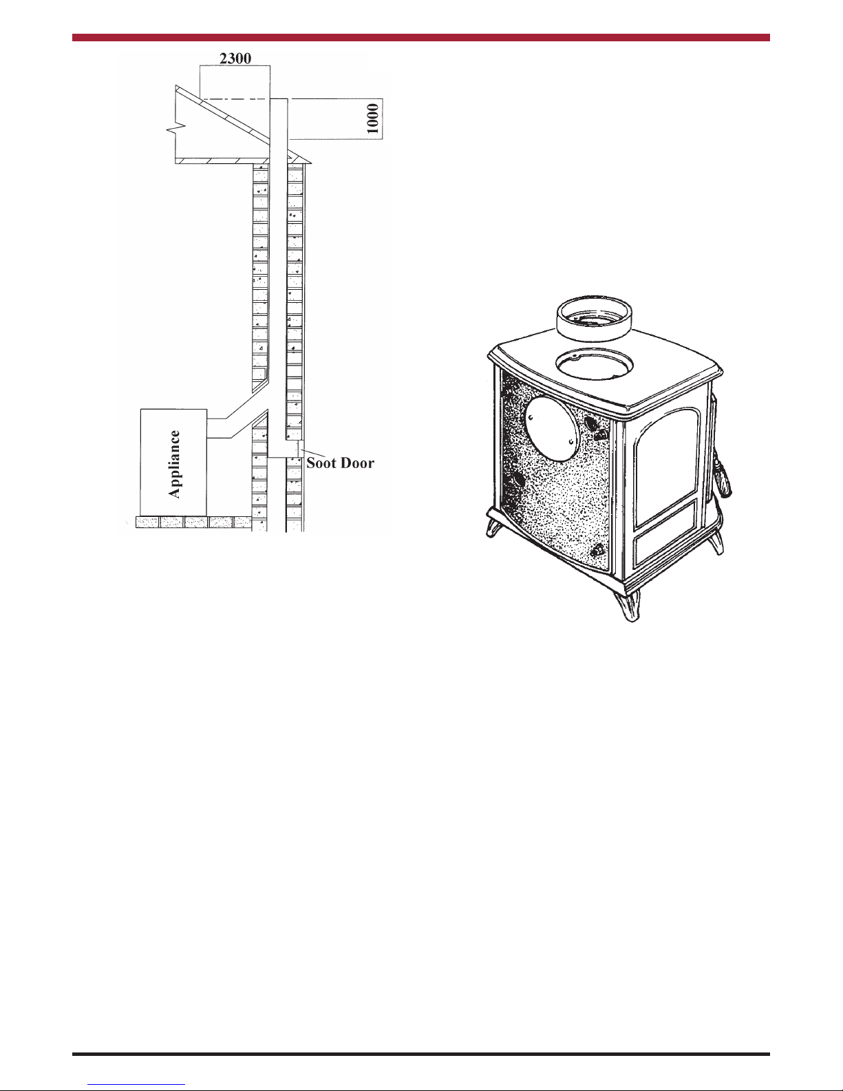
To minimise the wind effects, the flue termination
point should be located a minimum of 600mm from
the roof measured vertically and 2300mm measured
horizontally. Where this termination point does not
suffice it may be necessary to extend the flue pipe
so that the termination point is above the apex. See
Fig.1.
The installation must be completed in accordance
with current National and European Standards and
Local Codes. It should be noted that the requirements and these publications may be superseded
during the life of this manual.
CHIMNEY
The stove is a radiant room heater and must be connected to a chimney of the proper size and type. The
chimney must have a cross-sectional area of at least
124cm
2
or a diameter of at least 125mm. Never
connect to a smaller size chimney. Do not connect
to a chimney serving another appliance. Minimum
chimney height 4.5 meters from floor on which stove
is installed.
A flue that has proved to be unsatisfactory, particularly with regard to down draught should not be used
for venting this appliance until it has been examined
and any faults corrected.
An existing masonry chimney should be inspected
and if necessary repaired by a competent mason or
relined using an approved lining system. The stove
must be connected to a chimney with a minimum
continuous draught of 12 Pascal’s. Poor draught
conditions will result in poor performance. All register plates, restrictor plates, damper etc., which could
obstruct the flue at a future date should be removed
before connecting this appliance. If connecting to
an existing chimney with a flue diameter of more
than 150mm it is necessary to line the flue using a
suitable stainless steel flue liner. Where a masonry
Fig.1
chimney is not available a proprietary type 125 –
150mm twin wall, fully insulated pipe may be used.
The pipe must terminate at a point not lower than the
main ridge of adjacent outside obstructions. With
such installation, access to the chimney must be
provided for cleaning purposes. (See Fig.1)
When flue piping passes through a closure plate
with a sliding door, ensure that the pipe continues
up and is ultimately connected to the flue liner and
well sealed with fire cement.
TOP FLUE EXIT
For the top outlet configuration, remove the blanking
plate (part no.10) from the hob, remove the flue
spigot (part no.11) from the back plate and fix it to
the hob. Fix the outlet blanking plate to back plate
(see Fig. 2). Push the flue outlet connector pipe (not
supplied) into the flue spigot and cement into place
using approved fire cement, ensuring that no
cement is blocking the flue passageway.
REAR FLUE EXIT
Push the flue connector pipe (not supplied) into the
flue spigot and cement into place using approved
fire cement ensuring that no cement is blocking the
flue passageway.
Fig.2
4
 Loading...