

Page 1

Stanley Omnilock
a Product Group of Stanley Security Solutions, Inc.
1
Planning the installation
T83325/Rev A ER-7991-12 Jan 2010
Contents
These installation instructions describe how to install
your QAXOM Exit Device Lock. Topics covered
include:
Planning the installation...........................................1
Preparing the trim.......................................................3
Finishing the installation...........................................6
Site survey
Use the following survey to record information
about the installation site. You need this information
to determine how to prepare the door for the lock.
Door information
Door handing and bevel:
If a handing change is required, see “Set the hand”
on page 2.
❐ Left hand, reverse bevel (LHRB)
❐ Right hand, reverse bevel (RHRB)
Door thickness: 1-3/4 to 3 inches (44 to 75 mm).
Environment information
Model
Side of
door
Temperature
Range
Exposure
Standard Outside
+32°F to +129°F
0°C to +54°C
Drip proof.
Inadvertent
splashing of
water spray
acceptable.
Weatherized Outside
-4°F to +129°F
-20°C to +54°C
Direct exposure
to rain and snow
Extreme
Weatherized
Outside
-40°F to +129°F
-40°C to + 54°C
Direct exposure
to rain and snow
Inside
+32°F to +129°F
0°C to +54°C
N/A
Installation Instructions for
Stanley Omnilock QAXOM
Exit Device Locks
Components checklist
Your Stanley Omnilock package comes with the template, tailpiece and adapter plate for the model of
exit device being replaced. Use the following checklist to make sure that you have the items necessary to
install your Stanley QAXOM Exit Device Lock.
Components provided in the box:
❐ Adapter plate and tailpiece
❐ Outside escutcheon assembly
❐ Outside lever and spindle assembly
❐ Installation template and instructions
❐ Screw package
❐ Batteries
❐ 3/32 hex driver
Other components:
❐ Programming Default ID Card (provided with
software)
Page 2
Installation Instructions for Stanley Omnilock QAXOM Exit Device Locks
Stanley Omnilock
a Product Group of Stanley Security Solutions, Inc.
2
Planning the installation
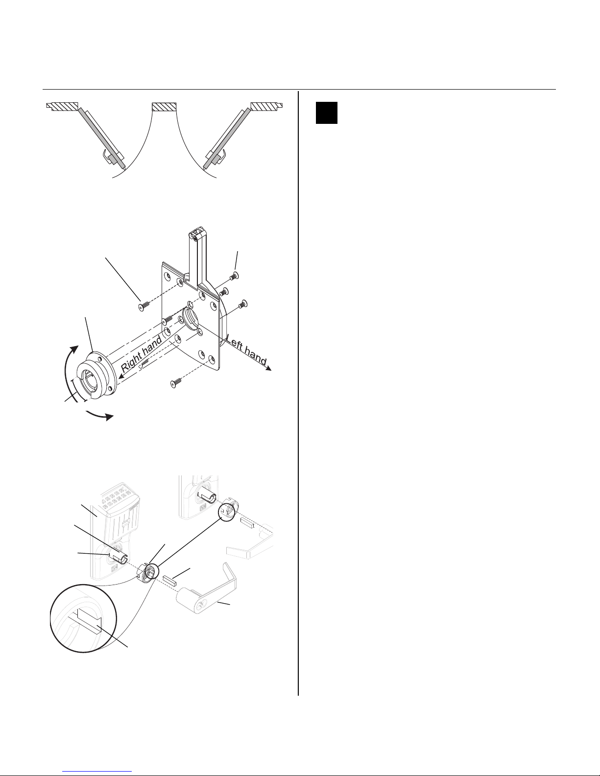
1 Set the hand
Your Omnilock Exit Device Lock comes preset for
right hand use. Should you need to change the lever
hand, please follow these steps:
Exit Device side (See Figure 2.)
1 Remove the spindle from the escutcheon
housing.
2 Release the four screws holding the back plate
onto the escutcheon housing. Retain these screws
for reinstallation.
3 Release the three screws holding the bearing on
to the escutcheon back plate. Retain these screws
for reinstallation.
4 Rotate the bearing 120 degrees, so that the
opening is in the correct hand position.
5 Reinstall the bearing to the back plate with the
retained screws.
6 Reinstall the back plate with the retained screws.
7 Replace the spindle, insuring the flange at the
rear of the spindle is properly in the bearing
groove.
Lever side (See Figure 3.)
1 Position the driver with the key slot in the desired
position. Rotate the spindle so that the lever catch
is opposite the driver key slot. The driver will set
flush to the escutcheon housing.
2 Place driver key in the slot.
3 See section 2 or 3 for installing the core or
cylinder in the lever.
Figure1 Door handing chart
LHRB
RHRB
Outside
Left Hand
Reverse
Bevel
Right Hand
Reverse
Bevel
Back plate
hex screws
Bearing
screws
Opening
Figure 2 Changing hand on the Exit Device side
Bearing
Right hand position shown
Figure 3 Changing hand on the levers
Driver key slot
Driver
Driver key
Escutcheon
Spindle
Lever
Right hand
Left hand
Lever
catch
Page 3
Installation Instructions for Stanley Omnilock QAXOM Exit Device Locks
Stanley Omnilock
a Product Group of Stanley Security Solutions, Inc.
3
Installation Instructions for Stanley Omnilock QAXOM Exit Device Locks
Preparing the trim
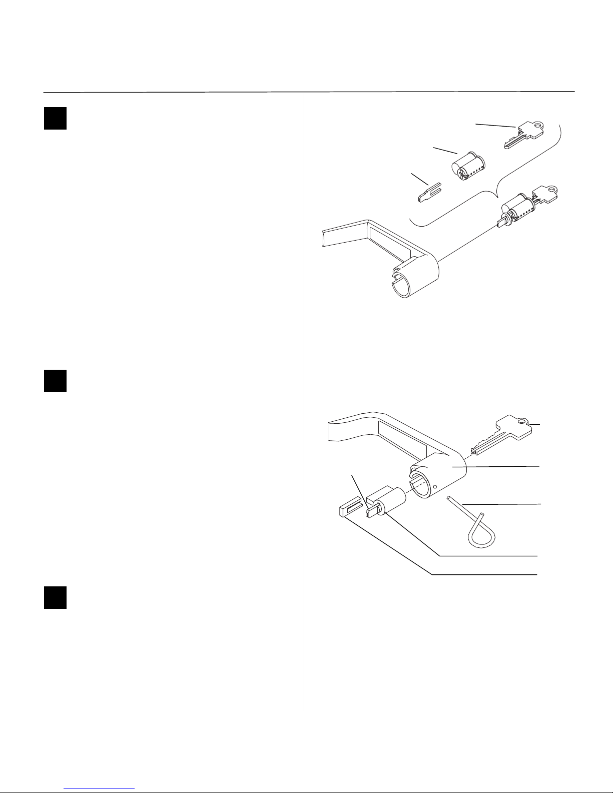
2 Install IC core and throw member
1 Slide the lever over the spindle up to the lever
catch. With a screwdriver in the center of the
spindle, retract the lever catch and slide on the
lever until it catches.
2 Insert the control key into the core and rotate the
key 15 degrees to the right.
3 Insert the throw member into the core.
4 Insert the core and throw member into the lever
with the control key
5 Return the control key to the original position
and withdraw the key.
6 To remove the lever, reverse steps 1 through 6.
Caution: The control key can be used to
remove cores and to access doors. Provide
adequate security for the control key.
3 Install standard key cylinder
1 Place the cylinder inside the lever. See Figure 5.
2 Install the retainer into the lever.
3 Insert the key into the cylinder and rotate the key
90 degrees clockwise. Slide the lever assembly
onto the spindle until the lever clicks as it
engages against the lever catch.
4 Pull on the lever to test that the lever catch is
engaged. Turn the key back to the original
position and remove it from the cylinder.
5 To remove the lever, insert the key and turn 90
degrees, then use the push pin to disengage the
lever catch on the spindle.
4 Prepare the door
1 Remove outside exit device trim and hardware
and discard.
2 Remove inside exit device chassis and retain for
reinstallation.
Figure 4 Installing the IC core
Throw member
Core
Control key
Figure 5 Installing a standard key cylinder
Key
Lever
Push pin
Retainer
Cylinder
Tab in
vertical position
Page 4

Installation Instructions for Stanley Omnilock QAXOM Exit Device Locks
Stanley Omnilock
a Product Group of Stanley Security Solutions, Inc.
4
Preparing the trim
5 Center punch and drill holes
Your Stanley Omnilock package comes with the template, tailpiece and adapter plate for the exit device
model you ordered.
1 Determine the location for the outside template
in accordance with instructions on the template.
2 Tape the template to the door.
3 Center punch the necessary drill points, or modify
existing holes as necessary.
4 Drill the holes.
5 Remove the template and follow steps 1 through
4 on the inside door.
Note: If installing the Extreme Weatherized
QAXOM, use the Extreme Weatherized template on
the inside door and repeat steps 1 through 4 for the
inside module as well.
6 Install batteries
Four alkaline AA batteries (or two weatherized packs
if installing a weatherized unit) are furnished with
your Omnilock system and must be installed before
proceeding with operation verification and system
installation.
Note: For the Extreme Weatherized model, see
section 8 on page 5.
1 Remove the gasket and battery cover from the
rear of the housing assembly as shown in Figure
6.
2 Install batteries with proper polarity as shown in
Figure 7. (For weatherized battery packs, simply
connect the wires from the battery pack to the
circuit board as shown in Figure 8.)
3 Press and hold the reset button on the circuit
board (as shown in Figure 7) until the green light
on the keypad flashes (about three seconds) then
release the button.
4 Replace the battery cover. See Figure 6. Make sure
that the tabs on the lower edge of the battery
cover are hooked over the edge of the back plate
and secure the cover with the screw.
Figure 6 Installing batteries
Housing assembly
AA Batteries
Battery cover
Gasket
Screw
EXTERNAL
Figure 7 Wall Mount System circuit board
Reset
button
Figure 8 Installing weatherized batteries
Reset Button
Page 5

Installation Instructions for Stanley Omnilock QAXOM Exit Device Locks
Stanley Omnilock
a Product Group of Stanley Security Solutions, Inc.
5
Installation Instructions for Stanley Omnilock QAXOM Exit Device Locks
Preparing the trim
5 Replace the gasket. See Figure 6. Make sure that it
is inside the edge of the housing.
7 Install the adapter plates
Note: The adapter plate shipped with your unit is
correct for the model ordered. It may not match the
illustration.
1 Line up the screws as shown in Figure 9.
2 Make sure the gasket is inside the edge of the
escutcheon housing.
3 For Extreme Weatherized models, thread the
connecting wires through the corresponding
hole. Ensure no wires are pinched.
4 Tighten screws.
8 Install the batteries for the Extreme
Weatherized module
1 On the inside module, thread the connecting
wires through the wire inlet hole near the bottom
center of the module.
2 Connect the pins and grounding wire as shown in
Figure 10.
3 Attach inside Extreme Weather module and cover
as shown in Figure 11.
Figure 9 Installing the adapter plate
Screws
Adapter plate
Escutcheon
Extreme
Escutcheon
Connecting wires
Weatherized
10 Pin
Connector
Grounding
wire
12 Pin
Connector
Cover
grounding
Wire inlet
Figure 10 Wire connections to circuit module
Figure 11 Installing the Extreme Weather module
Extreme Weatherized Module
Cover
Vertical
Centerline
Connecting wires
Place module close to exit device chassis
Page 6

Installation Instructions for Stanley Omnilock QAXOM Exit Device Locks
Stanley Omnilock
a Product Group of Stanley Security Solutions, Inc.
6
Finishing the installation
9 Tailpiece assembly
Note: The tailpiece assembly shipped with your unit
is correct for the model ordered. It may not match
the illustration.
1 Align the slot of the tailpiece driver vertically with
the throw member of the core.
2 Adjust the tailpiece to the proper depth for your
door.
• Hole A is used for doors sized 1 3/4, 2 1/4 or 2
3/4 inches thick
• Hole B is used on doors sized 2, 2 1/2 or 3
inches thick.
3 Adjust the tailpiece tab for the proper rotation,
according to the hand of the door.
• For LHRB doors, the tailpiece tab generally falls
at approximately the 1 to 3 o’clock position.
• For RHRB doors, the tailpiece tab falls
approximately at the 11 to 12 o’clock position.
4 Test fit the tailpiece with the exit device.
5 When correctly positioned, insert the roll pin.
Ensure that it is flush with the surface of the
tailpiece driver.
10 Exit device reassembly
Note: The tailpiece and adapter plate shipped with
your unit is correct for the model ordered. It may not
match the illustration.
1 Re-install the exit device on the door with
mounting screws.
2 Install the tailpiece assembly into the slot of the
exit device cam. (If your device is a Von Duprin
product, remove the plastic tailpiece guide, if
installed).
3 Install the adapter on the door so that the
tailpiece assembly enters the spindle of the lever
and the throw member of the key cylinder enters
the slot in the tailpiece driver. The posts on the
adapter plate enter the holes in the door. Do not
force.
Core throw
member
Tailpiece driver
Slot
Tailpiece
Roll pin
Hole A
Hole B
Tab
Figure 12 Assembling the tailpiece
Right hand position
Left hand position
Roll pin
Vertical position
Exit device cover
Exit device chassis
Tailpiece
Adapter
Figure 13 Reinstalling the exit device
Mounting screws
Adapter
screws
Page 7

Stanley Omnilock
a Product Group of Stanley Security Solutions, Inc.
7
Installation Instructions for Stanley Omnilock QAXOM Exit Device Locks
Finishing the installation
4 Install the screws to secure the exit device and the
adapter to the door.
5 Check for proper operation of the key bypass
feature by rotating the key to retract the latch.
Remove the key.
6 Install the exit device cover.
11 Check operation
Check the operation of the lock. For example, check
that:
❐ exit device latches and opens properly
❐ lever handle works
❐ key bypass feature works
For assistance, contact your local Stanley Omnilock
dealer.
12 Test Lock
To test the lock for proper operation before the lock
is programmed, follow these instructions:
For keypad locks
1 Press 1234 for the 2000 series, or 5011234
for the 500 series.
The green light flashes and the latch unlocks.
2 Turn the lever and open the door.
During the unlock time, the green light flashes. Then
the red light flashes and the latch relocks.
For magnetic stripe cards
1 Align the magnetic stripe card with the V mark by
the card slot.
2 Insert and then remove the card.
The green light flashes and the latch unlocks.
3 Turn the lever and open the door.
During the unlock time, if using the Programming
Default ID Card, the green light flashes. Then the red
light flashes and the latch relocks.
A label on the housing assembly battery cover
indicates the pre-set magnetic card track (track 2
or track 3) that the system is set to read.
For proximity cards
1 Align the proximity card over the recess on the
front of the escutcheon.
The green light flashes and the latch unlocks.
2 Turn the lever and open the door.
During the unlock time, if using the Programming
Default ID Card, the green light flashes. Then the red
light flashes and the latch relocks.
13 Troubleshooting
If the mechanism does not unlock, remove the battery cover and check for proper orientation and seating of the batteries and motor connector. Ensure
that wires are not pinched. Reset the electronics by
pressing and holding the reset button on the circuit
board until the light flashes green (approximately 3
seconds), then releasing the button. See Figure 14.
Note: The system will go through a self-test and the
green light will flash five times. You will hear the
lock unlock, then relock three times. A red flash
indicates a PC board or drive system problem. If a
red flash or no flash is observed, check for proper
orientation and seating of the batteries and motor
connector, ensure that wires are not pinched, then
repeat the reset process.
Figure 14 Using the reset button
Reset button
Motor connector
Red wire
Black wire
Page 8

Stanley Omnilock
a Product Group of Stanley Security Solutions, Inc.
8
 Loading...