

Page 1

Page 2

CREDITS/COPYRIGHT
Copyright © 2009 Stanley Security Solutions, Inc. and Stanley Logistics, Inc. All rights
reserved. Printed in the United States of America.
Information in this document is subject to change without notice and does not
represent a commitment on the part of Stanley Security Solutions, Inc. The software
described in this document are furnished under a license agreement or nondisclosure
agreement.
This publication is intended to be an accurate description and set of instructions
pertaining to its subject matter. However, as with any publication of this complexity,
errors or omissions are possible. Please call your BEST
Solutions, Inc., Best Access Systems at (317) 849-2250 if you see any errors or have any
questions. No part of this manual and/or databases may be reproduced or transmitted
in any form or by any means, electronic or mechanical, including photocopying,
recording, or information storage and retrieval systems, for any purpose, without the
express written permission of Stanley Security Solutions, Inc.
This document is distributed as is, without warranty of any kind, either express or
implied, respecting the contents of this book, including but not limited to implied
warranties for the publication’s quality, performance, merchantability, or fitness for any
particular purpose. Neither Stanley Security Solutions, Inc., nor its dealers or
distributors shall be liable to the user or any other person or entity with respect to any
liability, loss, or damage caused or alleged to be caused directly or indirectly by this
publication.
Sargent is a registered trademark of Sargent Manufacturing Co.
TORX is a registered trademark of the Camcar Division of Textron.
Von Duprin is a registered trademark of Von Duprin, Inc.
Written and designed by Stanley Security Solutions, Inc. and Avalon Group, Inc.,
Indianapolis, Indiana.
T83313 Rev – ER7991-6 November 2009
®
distributor or Stanley Security
Page 3

CONTENTS
FIGURES 1–VII
GETTING STARTED 1–1
Introduction 1–1
Product overview 1–3
Mortise lock overview 1–3
Cylindrical lock overview 1–4
Wall mount system overview 1–5
Exit hardware trim overview 1–6
Related service manuals 1–7
Technical support 1–7
Support services 1–7
Telephone technical support 1–7
STANDARD ESCUTCHEON ASSEMBLIES 2–1
Keypad reader escutcheon assembly 2–2
Magnetic stripe reader 2–5
Proximity reader 2–8
Dual validation reader (keypad and magnetic stripe) 2–11
Dual validation reader (keypad and proximity) 2–14
Weatherized escutcheon components 2–17
Extreme weatherized escutcheon components 2–18
Stanley OMNILOCK Illustrated Parts Catalog iii
Page 4

Contents
MORTISE COMPONENTS 3–1
Outside trim components 3–2
Inside trim components 3–3
Spindles 3–4
Mortise cases by function and option 3–5
Mortise case faceplates 3–6
Strike boxes and strike plates 3–7
Cylinder components 3–8
CYLINDRICAL COMPONENTS 4–1
Standard trim components 4–2
Standard levers 4–3
Cylindrical chassis 4–4
Latches 4–5
Strike boxes and strike plates 4–6
EXIT DEVICE TRIM COMPONENTS 5–1
Keypad reader escutcheon assembly 5–2
Magnetic stripe reader 5–4
Proximity reader 5–6
Dual validation reader (keypad and magnetic stripe) 5–8
Dual validation reader (keypad and proximity) 5–10
Weatherized escutcheon components 5–12
Adapter plate kits 5–13
Tailpiece kits 5–14
Outside levers 5–15
Other components 5–16
WALL MOUNT SYSTEM COMPONENTS 6–1
Keypad reader escutcheon assembly 6–2
Dual validation reader (keypad and magnetic stripe) 6–4
Dual validation reader (keypad and proximity) 6–6
Weatherized components 6–8
Extreme weatherized escutcheon components 6–9
5E cylinder components 6–11
iv Stanley OMNILOCK Illustrated Parts Catalog
Page 5

OTHER COMPONENTS 7–1
Programming devices, readers, and access cards 7–2
2000 Series management software 7–2
WAMS management software 7–2
Card readers and encoders 7–2
Wireless components 7–3
Single door controller 7–3
Portal gateway 7–3
Power-over-ethernet devices 7–4
Transformer 7–4
Modem 7–5
Antenna kits 7–6
Wireless conversion kit 7–7
Battery packs 7–7
Tools 7–7
Site survey kit and beacons 7–8
Contents
GLOSSARY A–1
Stanley OMNILOCK Illustrated Parts Catalog v
Page 6

Contents
vi Stanley OMNILOCK Illustrated Parts Catalog
Page 7

FIGURES
GETTING STARTED
Mortise lock overview diagram 1–3
Cylindrical lock overview diagram 1–4
Wall mount system overview diagram 1–5
Exit hardware trim overview diagram 1–6
STANDARD ESCUTCHEON ASSEMBLIES
Keypad reader escutcheon assembly (WAMS mortise shown) 2–2
Magnetic stripe reader escutcheon assembly (WAMS mortise shown) 2–5
Proximity reader escutcheon assembly (WAMS mortise shown) 2–8
Dual validation reader (keypad and magnetic stripe) escutcheon
assembly (WAMS mortise shown) 2–11
Dual validation reader-keypad and proximity escutcheon assembly
(WAMS mortise shown) 2–14
Weatherized escutcheon components 2–17
Extreme weatherized escutcheon components 2–18
MORTISE COMPONENTS
Outside mortise trim 3–2
Inside mortise trim 3–3
Spindles 3–4
Mortise case assembly 3–5
Mortise case faceplates 3–6
Mortise strike boxes and strike plates 3–7
Mortise cylinder components 3–8
Stanley OMNILOCK Illustrated Parts Catalog vii
Page 8

Figures
CYLINDRICAL COMPONENTS
Standard trim exploded view 4–2
Standard cylindrical levers 4–3
Cylindrical chassis 4–4
Cylindrical latches 4–5
Cylindrical strike boxes and strike plates 4–6
EXIT DEVICE TRIM COMPONENTS
Keypad reader escutcheon assembly (WAMS shown) 5–2
Magnetic stripe reader escutcheon assembly (WAMS shown) 5–4
Proximity reader escutcheon assembly (WAMS shown) 5–6
Dual validation reader (keypad and magnetic stripe) escutcheon
assembly (WAMS shown) 5–8
Dual validation reader (keypad and proximity) escutcheon assembly
(WAMS shown) 5–10
Weatherized escutcheon components 5–12
Adapter plates for exit device hardware trim 5–13
Tailpiece kit for exit device hardware trim 5–14
Outside levers for exit device hardware trim 5–15
Other components for exit device hardware trim 5–16
WALL MOUNT SYSTEM COMPONENTS
Keypad reader escutcheon assembly (500 series shown) 6–2
Dual validation reader (keypad and magnetic stripe) escutcheon
assembly (WAMS shown) 6–4
Dual validation reader (keypad and proximity) escutcheon assembly
(WAMS shown) 6–6
Weatherized components 6–8
Extreme weatherized escutcheon components 6–9
5E cylinder components for wall mount systems 6–11
viii Stanley OMNILOCK Illustrated Parts Catalog
Page 9

OTHER COMPONENTS
Card encoders 7–2
Single door controller 7–3
Portal gateway 7–3
Power-over-ethernet devices 7–4
Transformer 7–4
Modem 7–5
Antenna kits 7–6
Battery pack 7–7
Tools 7–7
Site survey kit and beacons components 7–8
GLOSSARY
Figures
Stanley OMNILOCK Illustrated Parts Catalog ix
Page 10

Figures
x Stanley OMNILOCK Illustrated Parts Catalog
Page 11

1
GETTING STARTED
INTRODUCTION
The Stanley OMNILOCK Illustrated Parts Catalog
contains essential information to help you maintain
your standalone OMNILOCK Wireless Access
Management System (WAMS), OMNILOCK 2000
Series, and OMNILOCK 500 Series products. Use this
manual to identify the part numbers you need to
order replacement and upgrade components.
OMNILOCK WAMS provides the convenience of a
wireless access control system. WAMS Locks support
up to 65,000 user codes per door, track up to 89,000
events, and are programmed using a PC-based
management system. The WAMS product family
includes:
■ 45HOM Mortise Lock with keypad reader,
magnetic stripe reader, dual validation magnetic
stripe and keypad reader, proximity reader, or
dual validation proximity and keypad reader
Stanley OMNILOCK Illustrated Parts Catalog 1–1
■ 93KOM–95KOM Cylindrical Lock with the same
reader options available for WAMS Mortise Locks
■ OMWMS Wall Mount System with dual validation
magnetic stripe and keypad reader or dual
validation proximity and keypad reader
■ QAXOM Exit Device Trim with the same reader
options available for WAMS Mortise Locks.
Page 12

Getting Started
OMNILOCK 2000 Series Locks support up to 2,000 user codes per
door, track up to 5,000 events, and are programmed using a PDA-based
management system. The 2000 Series includes:
■ 45HOM Mortise Lock with keypad reader, magnetic stripe reader,
dual validation magnetic stripe and keypad reader, proximity reader,
or dual validation proximity and keypad reader
■ 93KOM–95KOM Cylindrical Lock with the same reader options
available for 2000 Series Mortise Locks
■ OMWMS Wall Mount System with dual validation magnetic stripe
and keypad reader or dual validation proximity and keypad reader
■ QAXOM Exit Device Trim with the same reader options available for
2000 Series Mortise Locks.
OMNILOCK 500 Series Locks support up to 500 user codes per door,
track up to 750 events, and are programmed using a portable, wireless
printer device. The 500 Series includes:
■ 45HOM Mortise Lock with keypad reader
■ 93KOM–95KOM Cylindrical Lock with keypad reader
■ OMWMS Wall Mount System with keypad reader
■ OM500 Exit Device Trim with keypad reader.
Series
Reader options
Keypad
Magnetic stripe card
Proximity
Dual magnetic stripe and keypad
Dual proximity and keypad
OMNILOCK
500
OMNILOCK
2000
OMNILOCK
WAMS
1–2 Stanley OMNILOCK Illustrated Parts Catalog
Page 13
PRODUCT OVERVIEW
Outside
Inside
Getting Started
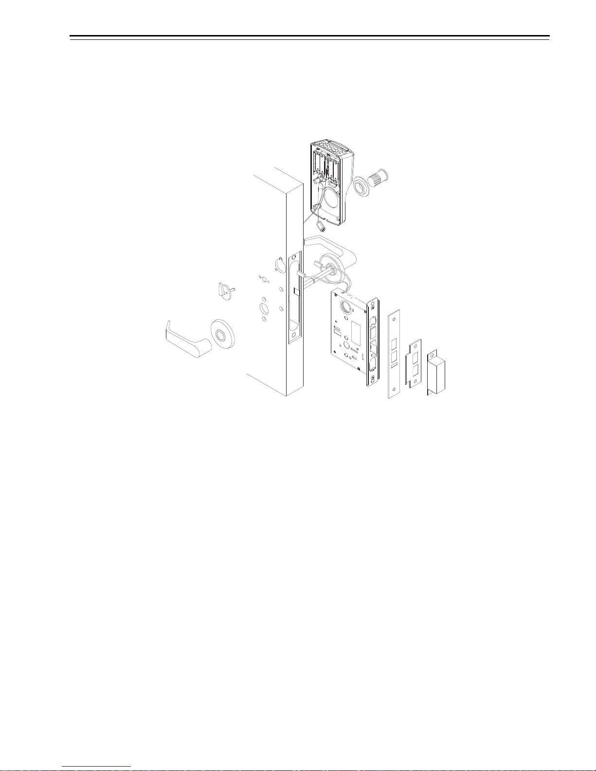
Mortise lock
overview
The diagram below shows an exploded view of the components of an
OMNILOCK Mortise Lock, indicating their orientation to the door.
Figure 1.1 Mortise lock overview diagram
Stanley OMNILOCK Illustrated Parts Catalog 1–3
Page 14
Getting Started
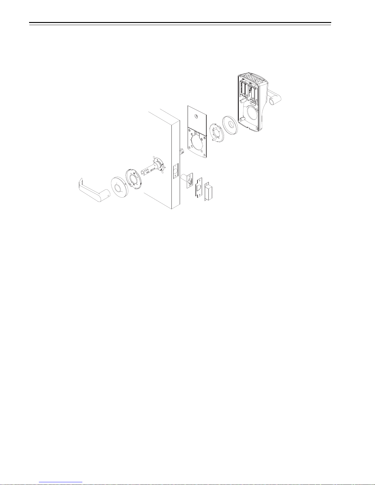
Outside
Inside
Cylindrical lock
overview
The diagram below shows an exploded view of the components of an
OMNILOCK Cylindrical Lock, indicating their orientation to the door.
Figure 1.2 Cylindrical lock overview diagram
1–4 Stanley OMNILOCK Illustrated Parts Catalog
Page 15
Getting Started
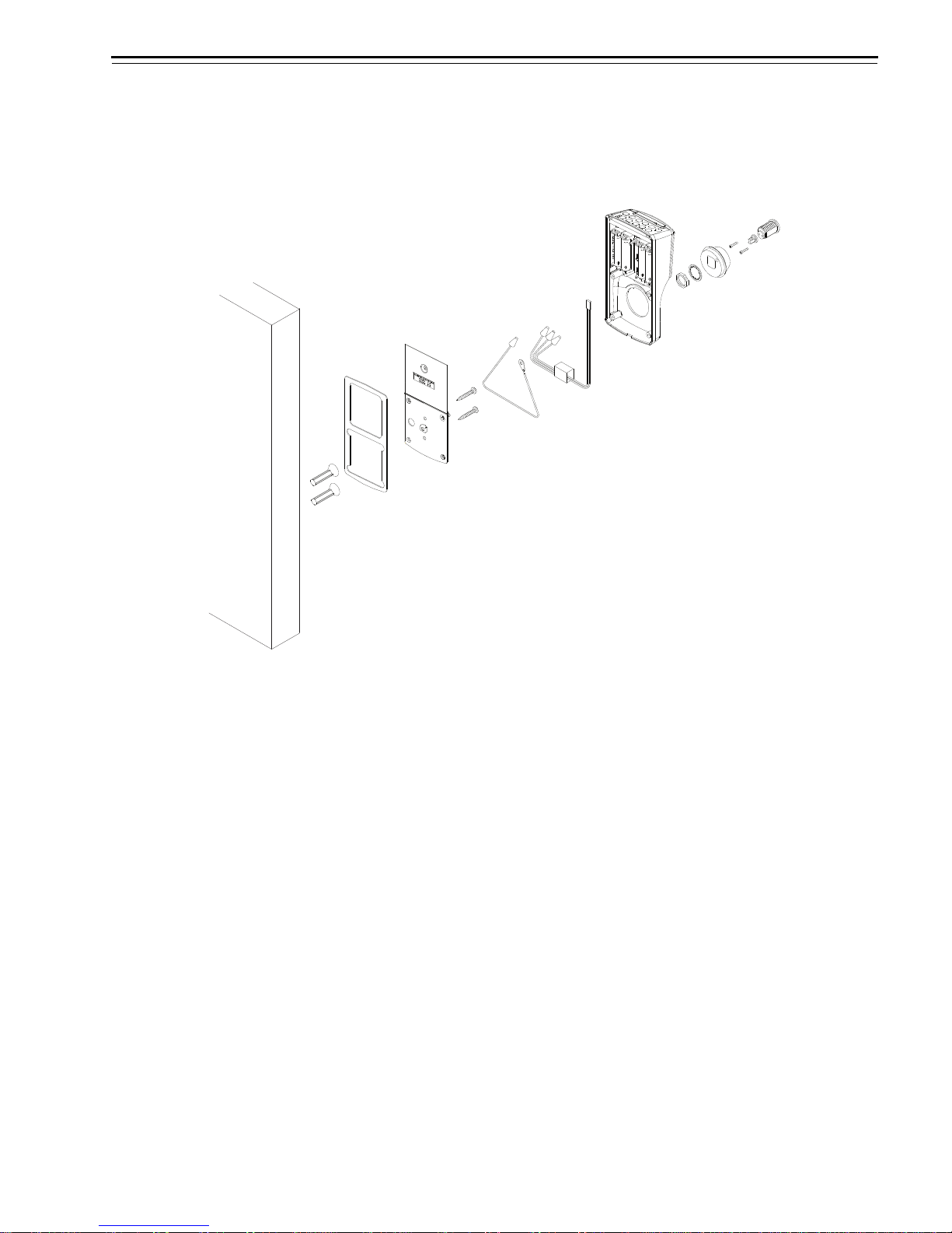
Outside
Wall mount
system
overview
The diagram below shows an exploded view of the components of an
OMNILOCK Wall Mount System.
Figure 1.3 Wall mount system overview diagram
Stanley OMNILOCK Illustrated Parts Catalog 1–5
Page 16
Getting Started
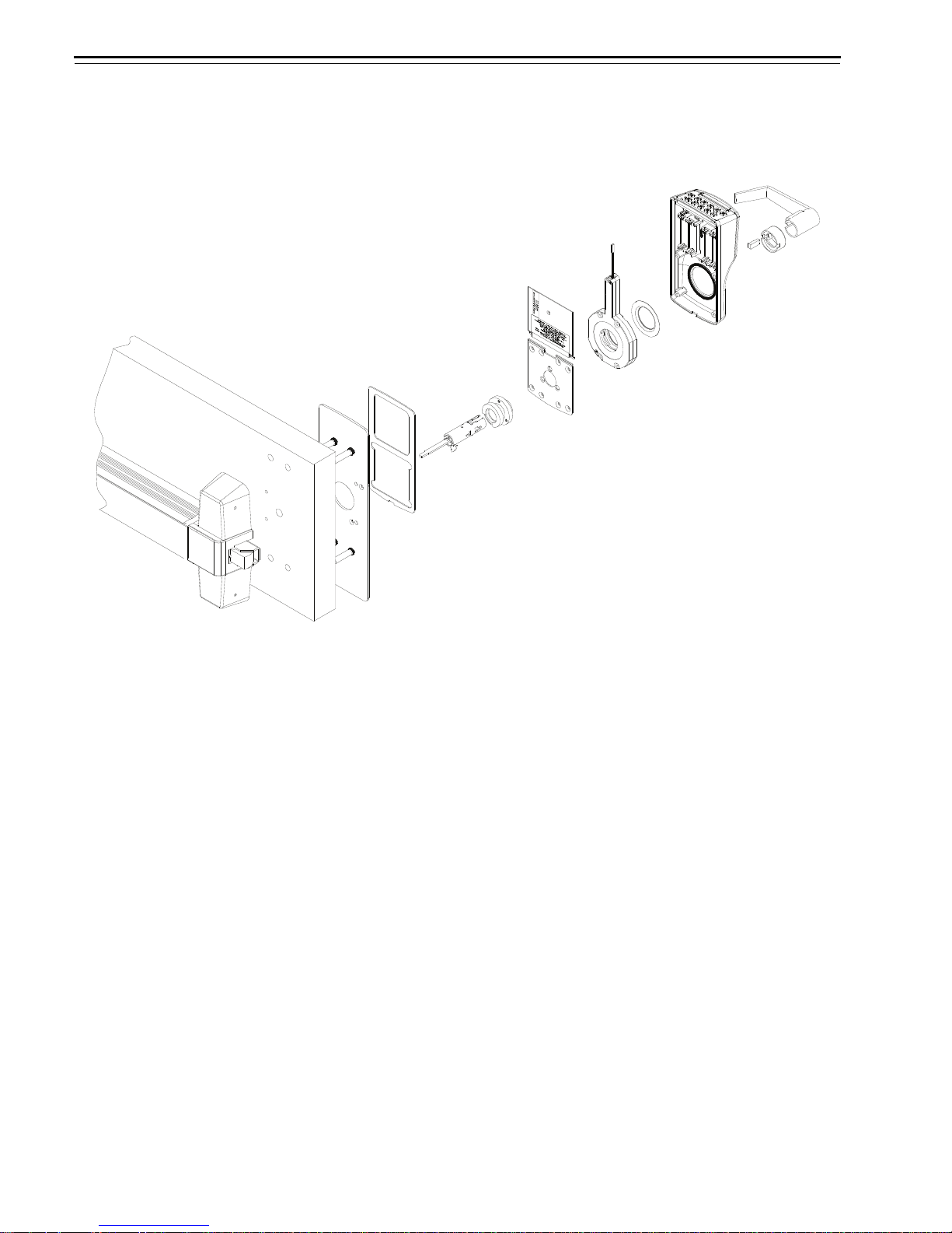
Outside
Inside
Exit hardware
trim overview
The diagram below shows an exploded view of the components of an
OMNILOCK Exit Hardware Trim application.
Figure 1.4 Exit hardware trim overview diagram
1–6 Stanley OMNILOCK Illustrated Parts Catalog
Page 17

RELATED SERVICE MANUALS
The service manuals referred to in this manual also can be ordered
separately:
Document Title Doc. No.
40H Series Service Manual T81602
9K Series Service Manual T56082
TECHNICAL SUPPORT
Getting Started
Support
services
Telephone
technical
support
When you need a part number for a component in an OMNILOCK Lock,
Wall Mount System, or Exit Hardware Trim application, your first
resource for help is the Stanley OMNILOCK Illustrated Parts Catalog.
If you cannot find the part number you need, contact your local
OMNILOCK Representative.
A factory-trained Certified Product Specialist (CPS) is available in your
area whenever you need help. Before you call, however, please make
sure that the product is in your immediate vicinity, and that you are
prepared to give the following information:
■ what happened and what you were doing when the problem arose
■ what you have done so far to correct the problem.
Stanley Security Solutions Representatives provide telephone technical
support for all OMNILOCK products. You may locate the
Representative nearest you by calling 1-800-392-5209 Monday through
Friday, between 8:00 a.m. and 5:00 p.m. eastern standard time; or visit
the web page www.OMNILOCK.com.
Stanley OMNILOCK Illustrated Parts Catalog 1–7
Page 18

Getting Started
1–8 Stanley OMNILOCK Illustrated Parts Catalog
Page 19

2
STANDARD ESCUTCHEON
ASSEMBLIES
This chapter provides exploded diagrams of the
escutcheon assemblies for standard OMNILOCK
Mortise and Cylindrical locks. Weatherized and
extreme weatherized escutcheon components are
described. This chapter also includes part numbers
for all field-serviceable parts.
Stanley OMNILOCK Illustrated Parts Catalog 2–1
Page 20
Standard Escutcheon Assemblies
2–2 Stanley OMNILOCK Illustrated Parts Catalog
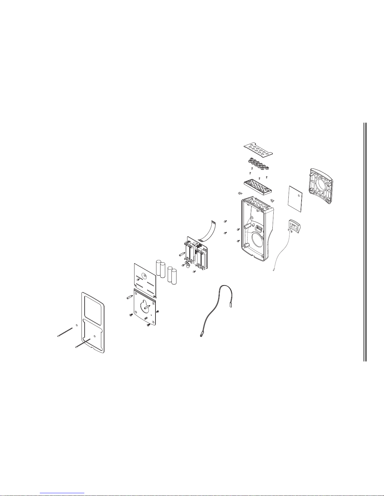
KEYPAD READER ESCUTCHEON ASSEMBLY
Keypad reader escutcheon assembly exploded view
Figure 2.1 Keypad reader escutcheon assembly (WAMS mortise shown)
+
+
+
-
+
-
-
-
3
5
4
9
1
2
6
7
8
10
11
13
15
12
17
18
19
20
25
21
22
23
24
27
16
26
14
5
5
Page 21

Standard Escutcheon Assemblies
Keypad reader
escutcheon
assembly parts list
Refer to Figure 2.1 and the table below to find the part you need.
WAMS
Item Qty.
Part No.
1 2 A82573 A82573 A82573 Standard door mounting screw
not shown
2 A82574 A82574 A82574 Thick door mounting screw
2 2 A82212 A82212 A82212 Flat nylon washer
3 1 B82267 B82267 B82267 Housing gasket
4 1 A82271 A82271 A82271 Battery cover
56bA82245 A82245 A82245 Escutcheon assembly screw
not shown
4 — — A82288 Cover mounting screw
6 1 B82296 B82296 B82296 Mortise mounting plate
not shown
1 B82277 B82277 B82277 Cylindrical mounting plate
7 2 A82300 A82300 A82300 Mounting plate standoff
82
c
B82272 B82272 B82272 Mounting plate screw
9 1 A82299 A82299 A82299 Grounding spring
2000 Series
Part No.
500 Series
Part No. Description
(1–1/4″ TORX
(mortise locks only)
(1–1/2″ TORX
(mortise locks only)
(mortise locks only)
(#4–40 × 1/4″ Phillips pan head)
(Phillips pan head)
(mortise locks only)
(#8–32 × 3/8″ Phillips flat head)
®
T15 button head)
®
T15 button head)
a
10 1 A82309 A82309 A82309 Grounding spring screw
(#6–32 × 1/4″ Phillips pan head)
11 1 A82265 A82265 A82265 Set of 4 batteries (AA alkaline, 1.5V)
12 1 3064470 3061490 3108402 Circuit board
e
13 1 A82086 A82086 A82086 Battery cover standoff
14 1 A82786 A82786 A82786 Cable clamp mounting screw
(mortise locks only)
15 1 A82554 A82554 A82554 Cable clamp
(mortise locks only)
16 1 B82852 B82852 B82852 Motor wire harness
17 1 A82249 A82249 A82249 Reader cable assembly
not shown
18 1 B82215 B82215 B82215 Reader housing
1 A82262 A82262 A82262 Cylindrical rose gasket
f
19 1 A82202 A82202 A82202 Left bezel spring
20 1 A82201 A82201 A82201 Right bezel spring
21 1 B82546 B82546 B82547 Keypad assembly
22 4 A82206 A82206 A82206 Keyboard mounting screw
(#4–40 × 1/4″ Phillips flat head)
23 1 B82242 B82242 B82242 Keypad key set
f
d
Stanley OMNILOCK Illustrated Parts Catalog 2–3
Page 22

Standard Escutcheon Assemblies
Item Qty.
WAMS
Part No.
2000 Series
Part No.
500 Series
Part No. Description
24 1 B82229 B82229 B82230 Keypad bezel
not shown
1 — B82243 B82243 IR window
25 1 3064554 — — Antenna assembly
26 1 A82291 A82291 A82291 Reader cover gasket
27 1 B82221 B82221 B82221 Front cover
a. For the part number for extreme weatherized battery covers, see Extreme weatherized
escutcheon components on page 2–18.
b. The 500 Series keypad reader escutcheon assembly uses two A82245 screws,
cylindrical applications use seven A82245 screws.
c. The cylindrical mounting plate uses four B82272 screws.
d. For the part numbers for weatherized batteries, see Weatherized escutcheon
components on page 2–17. For best performance, use Duracell or Energizer batteries.
e. For the part numbers for weatherized circuit boards, see Weatherized escutcheon
components on page 2–17. For part numbers for extreme weatherized circuit boards,
see Extreme weatherized escutcheon components on page 2–18.
f. Specify finish (gray, black, or satin chrome).
f
2–4 Stanley OMNILOCK Illustrated Parts Catalog
Page 23
Standard Escutcheon Assemblies
Stanley OMNILOCK Illustrated Parts Catalog 2–5
MAGNETIC STRIPE READER
Magnetic stripe reader escutcheon assembly exploded view
Figure 2.2 Magnetic stripe reader escutcheon assembly (WAMS mortise shown)
+
+
+
-
+
-
-
-
1
2
3
4
5
6
7
8
9
10
11
13
15
17
12
20
19
18
21
23
22
24
25
26
27
30
28
29
16
5
5
14
Page 24

Standard Escutcheon Assemblies
Magnetic stripe
reader escutcheon
assembly parts list
Refer to Figure 2.2 and the table below to find the part you need.
WAMS
Item Qty.
Part No.
1 2 A82573 A82573 Standard door mounting screw (1–1/4″ TORX®
not shown
2 A82574 A82574 Thick door mounting screw (1–1/2″ TORX®
2 2 A82212 A82212 Flat nylon washer
3 1 B82267 B82267 Housing gasket
4 1 A82271 A82271 Battery cover
56bA82245 A82245 Escutcheon assembly screw
6 1 B82296 B82296 Mortise mounting plate
not shown
1 B82277 B82277 Cylindrical mounting plate
7 2 A82300 A82300 Mounting plate standoff
82
c
B82272 B82272 Mounting plate screw
9 1 A82299 A82299 Grounding spring
2000 Series
Part No. Description
T15 button head) (mortise locks only)
T15 button head) (mortise locks only)
(mortise locks only)
a
(#4–40 × 1/4″ Phillips pan head)
(#8–32 × 3/8″ Phillips flat head)
10 1 A82309 A82309 Grounding spring screw
(#6–32 × 1/4″ Phillips pan head)
11 1 A82265 A82265 Set of 4 batteries (AA alkaline, 1.5V)
12 1 3064470 3061490 Circuit board
e
13 1 A82086 A82086 Battery cover standoff
14 1 A82786 A82786 Cable clamp mounting screw
(mortise locks only)
15 1 A82554 A82554 Cable clamp
(mortise locks only)
16 1 B82852 B82852 Motor wire harness
17 1 A82249 A82249 Reader cable assembly
18 1 A82210 A82210 Magnetic head spring
19 1 A82205 A82205 Magnetic head retaining ring
20 1 B82228 B82228 Magnetic head assembly
21 1 A82207 A82207 Magnetic head pivot pin
22 1 B82215 B82215 Reader housing
f
23 1 A82202 A82202 Left bezel spring
24 1 A82201 A82201 Right bezel spring
25 1 B82546 B82546 Keypad assembly
26 4 A82206 A82206 Keyboard mounting screw
(#4–40 × 1/4″ Phillips flat head)
d
27 1 B82211 B82211 Bezel
28 1 3064554 — Antenna assembly
2–6 Stanley OMNILOCK Illustrated Parts Catalog
Page 25

Standard Escutcheon Assemblies
Item Qty.
not shown
WAMS
Part No.
1 — B82243 IR window
2000 Series
Part No. Description
29 1 A82208 A82208 Magnetic head pin
30 1 B82222 B82222 Front cover
a. For the part number for extreme weatherized battery covers, see Extreme weatherized
escutcheon components on page 2–18.
b. Cylindrical applications use seven A82245 screws.
c. The cylindrical mounting plate uses four B82272 screws.
d. For the part numbers for weatherized batteries, see Weatherized escutcheon
components on page 2–17. For best performance, use Duracell or Energizer batteries.
e. For the part numbers for weatherized circuit boards, see Weatherized escutcheon
components on page 2–17. For part numbers for extreme weatherized circuit boards,
see Extreme weatherized escutcheon components on page 2–18.
f. Specify finish (gray, black, or satin chrome).
f
Stanley OMNILOCK Illustrated Parts Catalog 2–7
Page 26
Standard Escutcheon Assemblies
2–8 Stanley OMNILOCK Illustrated Parts Catalog
PROXIMITY READER
Proximity reader escutcheon assembly exploded view
Figure 2.3 Proximity reader escutcheon assembly (WAMS mortise shown)
+
+
+
-
+
-
-
-
1
2
3
4
7
8
5
6
9
10
11
12
13
15
17
19
18
20
22
23
24
25
26
27
29
30
31
32
16
28
5
5
21
14
Page 27

Standard Escutcheon Assemblies
Proximity reader
escutcheon
assembly parts list
Refer to Figure 2.3 and the table below to find the part you need.
WAMS
Item Qty.
Part No.
1 2 A82573 A82573 Standard door mounting screw (1–1/4″ TORX®
not shown
2 A82574 A82574 Thick door mounting screw (1–1/2″ TORX®
2 2 A82212 A82212 Flat nylon washer
3 1 B82267 B82267 Housing gasket
4 1 A82271 A82271 Battery cover
56bA82245 A82245 Escutcheon assembly screw
6 1 B82296 B82296 Mortise mounting plate
not shown
1 B82277 B82277 Cylindrical mounting plate
7 2 A82300 A82300 Mounting plate standoff
82
c
B82272 B82272 Mounting plate screw
9 1 A82299 A82299 Grounding spring
2000 Series
Part No. Description
T15 button head) (mortise locks only)
T15 button head) (mortise locks only)
(mortise locks only)
a
(#4–40 × 1/4″ Phillips pan head)
(#8–32 × 3/8″ Phillips flat head)
10 1 A82309 A82309 Grounding spring screw
(#6–32 × 1/4″ Phillips pan head)
11 1 A82265 A82265 Set of 4 batteries (AA alkaline, 1.5V)
12 1 3064470 3061490 Circuit board
e
13 1 A82086 A82086 Battery cover standoff
14 1 A82786 A82786 Cable clamp mounting screw
(mortise locks only)
15 1 A82554 A82554 Cable clamp
(mortise locks only)
16 1 B82852 B82852 Motor wire harness
17 1 A82249 A82249 Reader cable assembly
18 1 3062138 3062138 Proximity reader cable assembly
19 4 A82224 A82224 Proximity reader circuit board screw
(#2-56 Phillips pan head)
20 1 3062096 3062096 Proximity reader circuit board
21 4 A82225 A82225 Spacer
not shown
22 1 B82214 B82214 Proximity reader housing
1 A82262 A82262 Cylindrical rose gasket
f
23 1 A82202 A82202 Left bezel spring
24 1 A82201 A82201 Right bezel spring
d
Stanley OMNILOCK Illustrated Parts Catalog 2–9
25 1 B82546 B82546 Keypad assembly
26 4 A82206 A82206 Keyboard mounting screw
(#4–40 × 1/4″ Phillips flat head)
Page 28

Standard Escutcheon Assemblies
Item Qty.
WAMS
Part No.
2000 Series
Part No. Description
27 1 B82211 B82211 Bezel
28 1 3064554 — Antenna assembly
not shown
1 — B82243 IR window
29 1 A82291 A82291 Cover gasket
30 1 3062337 2062337 Clear tubing
31 1 B82293 B82293 Proximity reader antenna
32 1 B82223 B82223 Front cover
a. For the part number for extreme weatherized battery covers, see Extreme weatherized
escutcheon components on page 2–18.
b. Cylindrical applications use seven A82245 screws.
c. The cylindrical mounting plate uses four B82272 screws.
d. For the part numbers for weatherized batteries, see Weatherized escutcheon
components on page 2–17. For best performance, use Duracell or Energizer batteries.
e. For the part numbers for weatherized circuit boards, see Weatherized escutcheon
components on page 2–17. For part numbers for extreme weatherized circuit boards,
see Extreme weatherized escutcheon components on page 2–18.
f. Specify finish (gray, black, or satin chrome).
f
2–10 Stanley OMNILOCK Illustrated Parts Catalog
Page 29

Standard Escutcheon Assemblies
Stanley OMNILOCK Illustrated Parts Catalog 2–11
DUAL VALIDATION READER (KEYPAD AND MAGNETIC STRIPE)
Dual validation reader (keypad and magnetic stripe) escutcheon assembly exploded view
Figure 2.4 Dual validation reader (keypad and magnetic stripe) escutcheon assembly (WAMS mortise shown)
+
+
+
-
+
-
-
-
1
2
3
4
5
7
8
9
10
11
12
13
15
17
19
18
20
21
22
23
24
25
26
27
28
30
29
31
6
14
16
5
5
Page 30

Standard Escutcheon Assemblies
Dual validation
reader (keypad and
magnetic stripe)
escutcheon
assembly parts list
Refer to Figure 2.4 and the table below to find the part you need.
WAMS
Item Qty.
1 2 A82573 A82573 Standard door mounting screw (1–1/4″ TORX®
not shown
2 2 A82212 A82212 Flat nylon washer
3 1 B82267 B82267 Housing gasket
4 1 A82271 A82271 Battery cover
56bA82245 A82245 Escutcheon assembly screw
6 1 B82296 B82296 Mortise mounting plate
not shown
7 2 A82300 A82300 Mounting plate standoff
82
9 1 A82299 A82299 Grounding spring
Part No.
2 A82574 A82574 Thick door mounting screw (1–1/2″ TORX®
1 B82277 B82277 Cylindrical mounting plate
c
B82272 B82272 Mounting plate screw
2000 Series
Part No. Description
T15 button head) (mortise locks only)
T15 button head) (mortise locks only)
(mortise locks only)
a
(#4–40 × 1/4″ Phillips pan head)
(#8–32 × 3/8″ Phillips flat head)
10 1 A82309 A82309 Grounding spring screw
(#6–32 × 1/4″ Phillips pan head)
11 1 A82265 A82265 Set of 4 batteries (AA alkaline, 1.5V)
12 1 3064470 3061490 Circuit board
13 1 A82086 A82086 Battery cover standoff
14 1 A82786 A82786 Cable clamp mounting screw
(mortise locks only)
15 1 A82554 A82554 Cable clamp
(mortise locks only)
16 1 B82852 B82852 Motor wire harness
17 1 A82249 A82249 Reader cable assembly
18 1 A82210 A82210 Magnetic head spring
19 1 A82205 A82205 Magnetic head retaining ring
20 1 B82228 B82228 Magnetic head assembly
21 1 A82207 A82207 Magnetic head pivot pin
not shown
22 1 B82215 B82215 Reader housing
23 1 A82202 A82202 Left bezel spring
24 1 A82201 A82201 Right bezel spring
25 1 B82546 B82546 Keypad assembly
1 A82262 A82262 Cylindrical rose gasket
e
f
d
26 4 A82206 A82206 Keyboard mounting screw
27 1 B82242 B82242 Set of keypad keys
2–12 Stanley OMNILOCK Illustrated Parts Catalog
(#4–40 × 1/4″ Phillips flat head)
f
Page 31

Standard Escutcheon Assemblies
Item Qty.
WAMS
Part No.
2000 Series
Part No. Description
28 1 B82229 B82229 Keypad bezel
not shown
1 — B82243 IR window
29 1 3064554 — Antenna assembly
30 1 A82208 A82208 Magnetic head pin
31 1 B82222 B82222 Front cover
a. For the part number for extreme weatherized battery covers, see Extreme weatherized
escutcheon components on page 2–18.
b. Cylindrical applications use seven A82245 screws.
c. The cylindrical mounting plate uses four B82272 screws.
d. For the part numbers for weatherized batteries, see Weatherized escutcheon
components on page 2–17. For best performance, use Duracell or Energizer batteries.
e. For the part numbers for weatherized circuit boards, see Weatherized escutcheon
components on page 2–17. For part numbers for extreme weatherized circuit boards,
see Extreme weatherized escutcheon components on page 2–18.
f. Specify finish (gray, black, or satin chrome).
f
Stanley OMNILOCK Illustrated Parts Catalog 2–13
Page 32

Standard Escutcheon Assemblies
2–14 Stanley OMNILOCK Illustrated Parts Catalog
DUAL VALIDATION READER (KEYPAD AND PROXIMITY)
Dual validation reader (keypad and proximity) escutcheon assembly exploded view
Figure 2.5 Dual validation reader-keypad and proximity escutcheon assembly (WAMS mortise shown)
+
+
+
-
+
-
-
-
1
2
3
4
5
6
7
8
9
10
11
12
17
13
15
18
19
20
23
24
26
27
28
30
16
31
32
33
22
25
29
5
5
21
14
Page 33

Standard Escutcheon Assemblies
Dual validation
reader (keypad and
proximity)
escutcheon
assembly parts list
Refer to Figure 2.5 and the table below to find the part you need.
WAMS
Item Qty.
1 2 A82573 A82573 Standard door mounting screw (1–1/4″ TORX®
not shown
2 2 A82212 A82212 Flat nylon washer
3 1 B82267 B82267 Housing gasket
4 1 A82271 A82271 Battery cover
56bA82245 A82245 Escutcheon assembly screw
6 1 B82296 B82296 Mortise mounting plate
not shown
7 2 A82300 A82300 Mounting plate standoff
82
9 1 A82299 A82299 Grounding spring
Part No.
2 A82574 A82574 Thick door mounting screw (1–1/2″ TORX®
1 B82277 B82277 Cylindrical mounting plate
c
B82272 B82272 Mounting plate screw
2000 Series
Part No. Description
T15 button head) (mortise locks only)
T15 button head) (mortise locks only)
(mortise locks only)
a
(#4–40 × 1/4″ Phillips pan head)
(#8–32 × 3/8″ Phillips flat head)
10 1 A82309 A82309 Grounding spring screw
(#6–32 × 1/4″ Phillips pan head)
11 1 A82265 A82265 Set of 4 batteries (AA alkaline, 1.5V)
12 1 3064470 3061490 Circuit board
13 1 A82086 A82086 Battery cover standoff
14 1 A82786 A82786 Cable clamp mounting screw
(mortise locks only)
15 1 A82554 A82554 Cable clamp
(mortise locks only)
16 1 B82852 B82852 Motor wire harness
17 1 A82249 A82249 Reader cable assembly
18 1 3062138 3062138 Proximity reader cable assembly
19 4 A82224 A82224 Proximity reader circuit board screw
(#2–56 Phillips pan head)
20 1 3062096 3062096 Proximity reader circuit board
21 4 A82225 A82225 Spacer
22 1 B82214 B82214 Proximity reader housing
23 1 A82202 A82202 Left bezel spring
24 1 A82201 A82201 Right bezel spring
25 1 B82546 B82546 Keypad assembly
e
f
d
Stanley OMNILOCK Illustrated Parts Catalog 2–15
26 4 A82206 A82206 Keyboard mounting screw
(#4–40 × 1/4″ Phillips flat head)
27 1 B82242 B82242 Set of keypad keys
f
Page 34

Standard Escutcheon Assemblies
Item Qty.
WAMS
Part No.
2000 Series
Part No. Description
28 1 B82229 B82229 Keypad bezel
not shown
1 — B82243 IR window
29 1 3064554 — Antenna assembly
30 1 A82291 A82291 Cover gasket
31 1 3062337 2062337 Clear tubing
32 1 B82293 B82293 Proximity reader antenna
33 1 B82223 B82223 Front cover
a. For the part number for extreme weatherized battery covers, see Extreme weatherized
escutcheon components on page 2–18.
b. Cylindrical applications use seven A82245 screws.
c. The cylindrical mounting plate uses four B82272 screws.
d. For the part numbers for weatherized batteries, see Weatherized escutcheon
components on page 2–17. For best performance, use Duracell or Energizer batteries.
e. For the part numbers for weatherized circuit boards, see Weatherized escutcheon
components on page 2–17. For part numbers for extreme weatherized circuit boards,
see Extreme weatherized escutcheon components on page 2–18.
f. Specify finish (gray, black, or satin chrome).
f
2–16 Stanley OMNILOCK Illustrated Parts Catalog
Page 35

WEATHERIZED ESCUTCHEON COMPONENTS
12
Figure 2.6 Weatherized escutcheon components
Standard Escutcheon Assemblies
Weatherized
escutcheon
components list
Weatherized escutcheon assemblies include all of the components
listed for the corresponding standard escutcheon assembly except for
the battery pack and circuit board. Refer to Figure 2.6 and the table
below to find the part you need.
WAMS
Item Qty.
1 2 3092031 3092031 3092031 Weatherized battery pack
2 1 3103378 3092005 3109736 Weatherized circuit board
a. The weatherized circuit board is not sold individually. It is provided with weatherized
housing assemblies.
Part No.
2000 Series
Part No.
500 Series
Part No. Description
(alkaline 3V)
a
Stanley OMNILOCK Illustrated Parts Catalog 2–17
Page 36

Standard Escutcheon Assemblies
2–18 Stanley OMNILOCK Illustrated Parts Catalog
EXTREME WEATHERIZED ESCUTCHEON COMPONENTS
Extreme weatherized escutcheon components exploded view
Figure 2.7 Extreme weatherized escutcheon components
-
-
+
+
+
+
-
-
1
3
2
4
5
6
7
8
9
10
12
13
14
15
16
Outside of door
Inside of door
11
Page 37

Standard Escutcheon Assemblies
Extreme
weatherized
escutcheon
parts list
The extreme weatherized option is available for OMNILOCK 500 Series
and 2000 Series Locks. Extreme weatherized escutcheon assemblies
include all of the components listed for the corresponding standard
escutcheon assembly except for the battery cover and circuit board.
They also include the additional components listed below. Refer to
Figure 2.7 and the table below to find the part you need.
2000 Series
Item Qty.
1 1 B82856 B82856 Weatherized reader battery cover
2 1 B82857 B82857 Wire assembly
3 1 3092430 3092430 Weatherized circuit board
4 1 B82747 B82747 Interior electronics housing
5 2 A82575 A82575 Screw (#8–32 × 3/4″ TORX
6 1 A82555 A82555 Nut
7 1 A83017 A83017 Wire assembly
8 1 A82269 A82269 Foam pad
9 1 A82265 A82265 Set of 4 batteries (AA alkaline, 1.5V)
10 4 A82245 A82245 Screw (#4–40 × 1/4″ Phillips pan head)
Part No.
500 Series
Part No. Description
a
®
T15 button head)
11 1 3108334 3107901 Weatherized circuit board
12 1 O10665-2 O10665-2 Nut
13 1 O11706-1 O11706-1 Quick disk terminal
14 4 O10421-1 O10421-1 Housing bracket screw (#8 × 1/2″ )
15 1 B82748 B82748 Housing bracket
16 1 O10951 O10951 Housing bracket gasket
a. The weatherized circuit board is not sold individually. It is provided with weatherized
housing assemblies.
Stanley OMNILOCK Illustrated Parts Catalog 2–19
Page 38

Standard Escutcheon Assemblies
2–20 Stanley OMNILOCK Illustrated Parts Catalog
Page 39

3
MORTISE COMPONENTS
This chapter provides diagrams and part numbers for
the inside trim, outside trim, and lock cases for
standard OMNILOCK Mortise Locks. It also describes
the case faceplates, strike boxes, strike plates, and
cylinders for OMNILOCK Mortise Locks.
Stanley OMNILOCK Illustrated Parts Catalog 3–1
Page 40

Mortise Components
Outside rose assembly
#3 outside lever
assembly
#14 outside lever
assembly
#15 outside lever
assembly
#16 outside lever
assembly
OUTSIDE TRIM COMPONENTS
Outside trim
parts list
Figure 3.1 Outside mortise trim
Refer to Figure 3.1 and the table below to find the part you need. For
thick door part numbers, see the 40H Series Service Manual.
Finish and Part Number
Item 612
#3 outside lever assembly 1899574 1899616 1899815 1899930
#14 outside lever assembly 1900537 1900579 1900778 1900893
#15 outside lever assembly 1901059 1901090 1901290 1901415
#16 outside lever assembly 1898770 1898811 1899019 1899134
Outside rose assembly 1895187 1895229 1895428 1895543
a. Satin bronze, clear coated finish.
b. Oxidized satin bronze, oil rubbed finish.
c. Satin chromium plated finish.
d. Dark bronze, powder coated finish.
a
613
b
626
c
690
d
3–2 Stanley OMNILOCK Illustrated Parts Catalog
Page 41

INSIDE TRIM COMPONENTS
#3 inside lever
assembly
#14 inside lever
assembly
#15 inside lever
assembly
#16 inside lever
assembly
Inside rose
assembly
Optional
turn knob
Mortise Components
Figure 3.2 Inside mortise trim
Inside trim parts list Refer to Figure 3.2 and the table below to find the part you need.
Finish and Part Number
Item 612
#3 inside lever assembly 1894670 1894712 1894911 1895035
#14 inside lever assembly 1895632 1895674 1895873 1895999
#15 inside lever assembly 1896154 1896196 1896395 1896510
#16 inside lever assembly 1905933 1905975 1906172 1906298
Inside rose assembly 1895171 1895213 1895412 1895538
Inside rose assembly with turn knob 1902094 1902136 1902335 1902450
a. Satin bronze, clear coated finish.
b. Oxidized satin bronze, oil rubbed finish.
c. Satin chromium plated finish.
d. Dark bronze, powder coated finish.
a
613
b
626
c
690
d
Stanley OMNILOCK Illustrated Parts Catalog 3–3
Page 42

Mortise Components
Outside spindle
Inside spindle
SPINDLES
Figure 3.3 Spindles
Spindles parts list Refer to Figure 3.3 and the table below to find the part you need.
Part Number
Door Thickness
2″ B34016 B44210
2 1/4″ B34016 B44211
2 1/2″ B34016 B44212
2 3/4″ B34016 A44221
3″ B34165 A44222
3 1/4″ B34165 A44223
3 1/2″ B34165 A44224
3 3/4″ B34165 A44225
4″ B34165 A44226
4 1/4″ B34550 A44227
4 1/2″ B34550 A44228
4 3/4″ B34550 A44229
5″ B34550 A44230
a. The part numbers provided are for installations where
the mortise case is centered on the door.
b. If your door thickness measurements are in between
those listed, round up.
c. The A63101 pin is required for all outside spindles. It is
ordered separately from the spindle.
b
Inside Outside
a
c
3–4 Stanley OMNILOCK Illustrated Parts Catalog
Page 43

MORTISE CASES BY FUNCTION AND OPTION
Figure 3.4 Mortise case assembly
Mortise Components
Mortise case
assemblies
Refer to the tables below to find the case assembly you need.
Part Number
DV
Sensor Option
None C45741 C45743
Key override switch C44639 C44638
Request-to-exit switch
Key override switch and request-to-exit switch
Key override switch, request-to-exit switch, and
door status switch
Key override switch, request-to-exit switch, door status
switch, and latch status switch
Request-to-exit switch, door status switch, and
latch status switch
Request-to-exit switch and door status switch
a. All mortise case assemblies include two A18724 case mounting screws
(#12–12 × 3/4″ Phillips flat head).
b. Available for WAMS Mortise Locks only.
b
b
b
b
b
b
Function
C44649 C44641
C44644 —
C44642 —
C44643 —
C44649 —
a
— C44640
TV
Function
a
Stanley OMNILOCK Illustrated Parts Catalog 3–5
Page 44

Mortise Components
DV function
mortise faceplate
TV function
mortise faceplate
MORTISE CASE FACEPLATES
Mortise case
faceplates parts list
Figure 3.5 Mortise case faceplates
Refer to Figure 3.5 and the table below to find the part you need.
Finish and Part Number
Item 612
40H faceplate assembly (DV function)
40H faceplate assembly (TV function)
a. Satin bronze, clear coated finish.
b. Oxidized satin bronze, oil rubbed finish.
c. Satin chromium plated finish.
d. Dark bronze, powder coated finish.
e. The assembly includes one faceplate and two faceplate screws (#8–32 × 1/4″ Phillips
flat head).
e
e
a
1895962 1896002 1896201 1896243
1895082 1895124 1895323 1895365
613
b
626
c
690
d
3–6 Stanley OMNILOCK Illustrated Parts Catalog
Page 45

STRIKE BOXES AND STRIKE PLATES
1
2
3
Figure 3.6 Mortise strike boxes and strike plates
Mortise Components
Strike boxes and
strike plates
parts list
Refer to Figure 3.6 and the table below to find the part you need.
Finish and Part Number
Item 612
40H universal strike plate package
Plastic strike box B34380
Magnetic strike box for DV function
door status monitor
a. Satin bronze, clear coated finish.
b. Oxidized satin bronze, oil rubbed finish.
c. Satin chromium plated finish.
d. Dark bronze, powder coated finish.
e. The package includes one strike plate and two screws (#12–12 × 3/4″ Phillips
flat head).
f. This item is not finish specific.
e
a
1902969 1903009 1903208 1903323
613
b
B61224
626
f
f
c
690
d
Stanley OMNILOCK Illustrated Parts Catalog 3–7
Page 46

Mortise Components
IC Cylinder Dummy cylinder
CYLINDER COMPONENTS
Figure 3.7 Mortise cylinder components
Cylinder parts list Refer to Figure 3.7 and the table below to find the part you need.
Finish and Part Number
Item 612
IC cylinder and cam assembly
Dummy cylinder assembly
e
f
1307641 1878376 1307772 1307683
1292541 1292583 1292358 1792410
a
613
b
626
c
690
d
a. Satin bronze, clear coated finish.
b. Oxidized satin bronze, oil rubbed finish.
c. Satin chromium plated finish.
d. Dark bronze, powder coated finish.
e. The assembly includes one throw plug spacer, two throw pins, one throw plug,
one stamp head, one IC cylinder, one collar, and one cam.
f. The assembly includes two clamp screws, one clamp plate, and one dummy cylinder.
3–8 Stanley OMNILOCK Illustrated Parts Catalog
Page 47

4
CYLINDRICAL COMPONENTS
This chapter provides diagrams and part numbers for
the inside trim, outside trim, and lock chassis for
standard OMNILOCK Cylindrical Locks. It also
describes the latches, strike boxes, and strike plates,
for OMNILOCK Cylindrical Locks.
Stanley OMNILOCK Illustrated Parts Catalog 4–1
Page 48

Cylindrical Components
Inside rose
Through-bolt
screws
Inside rose liner
Outside rose liner
Outside rose
Inside rose liner with
request to exit
STANDARD TRIM COMPONENTS
Standard trim
exploded view
Figure 4.1 Standard trim exploded view
Standard trim
Refer to Figure 4.1 and the table below to find the part you need.
parts list
Item 612
Inside Rose 1593527 1593569 1593726 1781151
Two through-bolt screws B55557
Inside rose liner C55555
Inside rose liner with request to exit B82185
Outside rose liner A82180
Outside rose 3106850 3111420 3106819 3106892
a. Satin bronze, clear coated finish.
b. Oxidized satin bronze, oil rubbed finish.
c. Satin chromium plated finish.
d. Dark bronze, powder coated finish.
e. This item is not finish specific.
4–2 Stanley OMNILOCK Illustrated Parts Catalog
Finish and Part Number
a
613
b
626
e
e
e
e
c
690
d
Page 49

STANDARD LEVERS
#14 plain lever #15 plain lever #16 plain lever
#14 keyed lever #15 keyed lever #16 keyed lever
Standard levers
Cylindrical Components
Figure 4.2 Standard cylindrical levers
Standard levers list
Refer to Figure 4.2 and the table below to find the part you need.
Item 612
#14 plain lever 1602303 1602345 1602502 1763620
#15 plain lever 1747189 1747220 1747388 1788100
#16 plain lever 1580641 1580683 1580840 1814176
#14 keyed lever 1601734 1601776 1601933 1763504
#15 keyed lever 1736507 1736549 1736706 1781078
#16 keyed lever 1580662 1580704 1580861 1814218
#14 non IC Schlage / Corbin / Medeco 1890917 1890959 1891114 1911418
#15 non IC Schlage / Corbin / Medeco 1768675 1768717 1768874 1883716
#16 non IC Schlage / Corbin / Medeco 1891313 1891355 1891512 3125826
#14 non IC Sargent / Yale 1906675 1906717 1906832
#15 non IC Sargent / Yale 1768235 1768277 1768434 1913373
#16 non IC Sargent / Yale 1906990 1907030 1907155
#14 non IC Schlage large format 1907580 1907621 1907747
#15 non IC Schlage large format 1907904 1907946 1908060
a. Satin bronze, clear coated finish.
b. Oxidized satin bronze, oil rubbed finish.
c. Satin chromium plated finish.
d. Dark bronze, powder coated finish.
Finish and Part Number
a
613
b
626
c
d
690
not available
not available
not available
not available
Stanley OMNILOCK Illustrated Parts Catalog 4–3
Page 50

Cylindrical Components
CYLINDRICAL CHASSIS
Figure 4.3 Cylindrical chassis
Cylindrical
chassis list
Refer to the table below to find the chassis you need.
Part No. Chassis Type
D82170 9KOM standard and Schlage large format chassis
D82171 9KOM non-IC chassis
D82172 9KOM chassis with request to exit and door switch monitor
a. Available for WAMS Locks only.
a
4–4 Stanley OMNILOCK Illustrated Parts Catalog
Page 51

LATCHES
2 3/4″ Latch 2 3/4″ Latch with
3/4″ throw
3 3/4″ Latch 5″ Latch
Cylindrical Components
Figure 4.4 Cylindrical latches
Latches list Refer to Figure 4.4 and the table below to find the part you need.
Item 612
2 3/4″ Latch 1414488 1414520 1414645 1781235
2 3/4″ Latch with 3/4″ throw 1905027 1894471 1243824 1894471
3 3/4″ Latch 1415209 1415240 1415366 1792425
5″ Latch 1415607 1415649 1415738 1763546
a. Satin bronze, clear coated finish.
b. Oxidized satin bronze, oil rubbed finish.
c. Satin chromium plated finish.
d. Dark bronze, powder coated finish.
Finish and Part Number
a
613
b
626
c
690
d
Stanley OMNILOCK Illustrated Parts Catalog 4–5
Page 52

Cylindrical Components
ANSI strike package Standard strike package
STRIKE BOXES AND STRIKE PLATES
Figure 4.5 Cylindrical strike boxes and strike plates
Strike boxes and
strike plates
parts list
Refer to Figure 4.5 and the table below to find the part you need.
Finish and Part Number
Item 612
ANSI strike and screws 1228455 1228460 1228434 1781319
ANSI plastic strike box B34380
ANSI magnetized strike box B61224
Standard strike and screws 1228366 1228371 1228324 1905100
Standard steel strike box B25640
a. Satin bronze, clear coated finish.
b. Oxidized satin bronze, oil rubbed finish.
c. Satin chromium plated finish.
d. Dark bronze, powder coated finish.
e. This item is not finish specific.
a
613
b
626
e
e
e
c
690
d
4–6 Stanley OMNILOCK Illustrated Parts Catalog
Page 53

5
EXIT DEVICE TRIM
COMPONENTS
This chapter provides exploded diagrams of the
escutcheon assemblies for OMNILOCK Exit Device
Trim. It also describes Exit device adapter plate kits,
tailpiece kits, and outside levers. Weatherized and
extreme weatherized components also are included.
This chapter provides part numbers for all fieldserviceable parts.
Stanley OMNILOCK Illustrated Parts Catalog 5–1
Page 54

Exit Device Trim Components
5–2 Stanley OMNILOCK Illustrated Parts Catalog
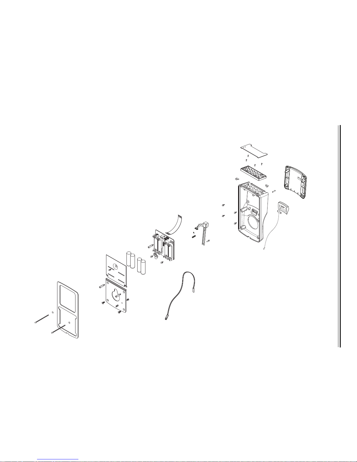
KEYPAD READER ESCUTCHEON ASSEMBLY
Keypad reader escutcheon assembly exploded view
Figure 5.1 Keypad reader escutcheon assembly (WAMS shown)
+
+
+
-
+
-
-
-
1
2
3
4
5
9
6
7
13
14
15
16
17
18
19
20
21
22
24
25
23
10
12
11
8
13
Page 55

Exit Device Trim Components
Keypad reader
escutcheon
assembly parts list
Refer to Figure 5.1 and the table below to find the part you need.
WAMS
Item Qty.
Part No.
1 1 B82267 B82267 B82267 Housing gasket
2 1 B82735 B82735 B82735 Exit device bearing
3 1 A82719 A82719 A82719 Battery cover screw
4 3 A82724 A82724 A82724 Mounting plate screw
5 1 A82723 A82723 A82723 Mounting plate screw
6 1 B82736 B82736 B82736 Battery cover
7 1 B82734 B82734 B82734 Exit device mounting plate
8 2 A82720 A82720 A82720 Battery cover pad
9 3 A82272 A82272 A82272 Mounting plate screw
10 1 B82745 B82745 B82745 Quick adapter assembly
11 1 B82738 B82738 B82738 Quick adapter rose
12 1 A82265 A82265 A82265 Set of 4 batteries (AA alkaline, 1.5V)
13 6
not shown
b
A82245 A82245 A82245 Escutcheon assembly screw
4 — — A82288 Cover mounting screw
14 1 3064470 3061490 3108402 Circuit board
2000 Series
Part No.
500 Series
Part No. Description
(#4–40 × 1″ Phillips flat head)
(#8–32 × 5/8″ Phillips flat head)
(#8–32 × 3/8″ Phillips flat head)
(#8–32 × 3/8″ Phillips flat head)
(#4–40 × 1/4″ Phillips pan head)
(Phillips pan head)
c
a
15 1 A82249 A82249 A82249 Reader cable assembly
16 1 B82215 B82215 B82215 Reader housing
d
17 1 A82202 A82202 A82202 Left bezel spring
18 1 A82201 A82201 A82201 Right bezel spring
19 1 B82546 B82546 B82547 Keypad assembly
20 4 A82206 A82206 A82206 Keyboard mounting screw
(#4–40 × 1/4″ Phillips flat head)
21 1 B82242 B82242 B82242 Set of keypad keys
d
22 1 B82229 B82229 B82230 Keypad bezel
not shown
1 — B82243 B82243 IR window
23 1 3064554 — — Antenna assembly
24 1 A82291 A82291 A82291 Reader cover gasket
25 1 B82221 B82221 B82221 Front cover
a. For the part numbers for weatherized batteries, see Weatherized escutcheon
components on page 5–12. For best performance, use Duracell or Energizer batteries.
b. The 500 Series keypad reader escutcheon assembly uses two A82245 screws.
c. For the part numbers for weatherized circuit boards, see Weatherized escutcheon
components on page 5–12.
d. Specify finish (gray, black, or satin chrome).
d
Stanley OMNILOCK Illustrated Parts Catalog 5–3
Page 56

Exit Device Trim Components
5–4 Stanley OMNILOCK Illustrated Parts Catalog
MAGNETIC STRIPE READER
Magnetic stripe reader escutcheon assembly exploded view
Figure 5.2 Magnetic stripe reader escutcheon assembly (WAMS shown)
+
+
+
-
+
-
-
-
1
2
3
4
5
9
6
7
13
14
15
10
12
11
8
13
16
17
18
19
20
21
22
27
26
28
23
24
25
Page 57

Exit Device Trim Components
Magnetic stripe
reader escutcheon
assembly parts list
Refer to Figure 5.2 and the table below to find the part you need.
WAMS
Item Qty.
Part No.
1 1 B82267 B82267 Housing gasket
2 1 B82735 B82735 Exit device bearing
3 1 A82719 A82719 Battery cover screw
4 3 A82724 A82724 Mounting plate screw
5 1 A82723 A82723 Mounting plate screw
6 1 B82736 B82736 Battery cover
7 1 B82734 B82734 Exit device mounting plate
8 2 A82720 A82720 Battery cover pad
9 3 A82272 A82272 Mounting plate screw
10 1 B82745 B82745 Quick adapter assembly
11 1 B82738 B82738 Quick adapter rose
12 1 A82265 A82265 Set of 4 batteries (AA alkaline, 1.5V)
2000 Series
Part No. Description
(#4–40 × 1″ Phillips flat head)
(#8–32 × 5/8″ Phillips flat head)
(#8–32 × 3/8″ Phillips flat head)
(#8–32 × 3/8″ Phillips flat head)
a
13 6 A82245 A82245 Escutcheon assembly screw
(#4–40 × 1/4″ Phillips pan head)
14 1 3064470 3061490 Circuit board
b
15 1 A82249 A82249 Reader cable assembly
16 1 A82210 A82210 Magnetic head spring
17 1 A82205 A82205 Magnetic head retaining ring
18 1 B82228 B82228 Magnetic head assembly
19 1 A82207 A82207 Magnetic head pivot pin
20 1 B82215 B82215 Reader housing
c
21 1 A82202 A82202 Left bezel spring
22 1 A82201 A82201 Right bezel spring
23 1 B82546 B82546 Keypad assembly
24 4 A82206 A82206 Keyboard mounting screw
(#4–40 × 1/4″ Phillips flat head)
25 1 B82211 B82211 Bezel
not shown
1 — B82243 IR window
26 1 3064554 — Antenna assembly
27 1 A82208 A82208 Magnetic head pin
28 1 B82222 B82222 Front cover
c
a. For the part numbers for weatherized batteries, see Weatherized escutcheon
b. For the part numbers for weatherized circuit boards, see Weatherized escutcheon
c. Specify finish (gray, black, or satin chrome).
Stanley OMNILOCK Illustrated Parts Catalog 5–5
components on page 5–12. For best performance, use Duracell or Energizer batteries.
components on page 5–12.
Page 58

Exit Device Trim Components
5–6 Stanley OMNILOCK Illustrated Parts Catalog
PROXIMITY READER
Proximity reader escutcheon assembly exploded view
Figure 5.3 Proximity reader escutcheon assembly (WAMS shown)
+
+
+
-
+
-
-
-
1
2
3
4
5
9
6
7
10
12
11
8
13
14
15
16
17
18
19
13
20
21
22
23
24
25
26
27
28
29
30
Page 59

Exit Device Trim Components
Proximity reader
escutcheon
assembly parts list
Refer to Figure 5.3 and the table below to find the part you need.
WAMS
Item Qty.
Part No.
1 1 B82267 B82267 Housing gasket
2 1 B82735 B82735 Exit device bearing
3 2 A82720 A82720 Battery cover pad
4 1 B82736 B82736 Battery cover
5 1 A82719 A82719 Battery cover screw
6 6 A82245 A82245 Escutcheon assembly screw
7 1 B82734 B82734 Exit device mounting plate
8 3 A82724 A82724 Mounting plate screw
9 1 A82723 A82723 Mounting plate screw
10 3 A82272 A82272 Mounting plate screw
11 1 B82745 B82745 Quick adapter assembly
12 1 B82738 B82738 Quick adapter rose
13 1 A82265 A82265 Set of 4 batteries (AA alkaline, 1.5V)
14 1 3064470 3061490 Circuit board
15 1 A82249 A82249 Reader cable assembly
16 1 3062138 3062138 Proximity reader cable assembly
17 4 A82224 A82224 Proximity reader circuit board screw
18 1 3062096 3062096 Proximity reader circuit board
19 4 A82225 A82225 Spacer
20 1 B82214 B82214 Reader housing
21 1 A82202 A82202 Left bezel spring
22 1 A82201 A82201 Right bezel spring
23 1 B82546 B82546 Keypad assembly
24 4 A82206 A82206 Keyboard mounting screw
25 1 B82211 B82211 Bezel
not shown
1 — B82243 IR window
26 1 3064554 — Antenna assembly
27 1 A82291 A82291 Reader cover gasket
28 1 3062337 2062337 Clear tubing
29 1 B82293 B82293 Proximity reader antenna
30 1 B82223 B82223 Front cover
2000 Series
Part No. Description
(#4–40 × 1″ Phillips flat head)
(#4–40 × 1/4″ Phillips pan head)
(#8–32 × 5/8″ Phillips flat head)
(#8–32 × 3/8″ Phillips flat head)
(#8–32 × 3/8″ Phillips flat head)
a
b
(#2-56 Phillips pan head)
c
(#4–40 × 1/4″ Phillips flat head)
c
a. For the part numbers for weatherized batteries, see Weatherized escutcheon
b. For the part numbers for weatherized circuit boards, see Weatherized escutcheon
c. Specify finish (gray, black, or satin chrome).
Stanley OMNILOCK Illustrated Parts Catalog 5–7
components on page 5–12. For best performance, use Duracell or Energizer batteries.
components on page 5–12.
Page 60

Exit Device Trim Components
5–8 Stanley OMNILOCK Illustrated Parts Catalog
DUAL VALIDATION READER (KEYPAD AND MAGNETIC STRIPE)
Dual validation reader (keypad and magnetic stripe) escutcheon assembly exploded view
Figure 5.4 Dual validation reader (keypad and magnetic stripe) escutcheon assembly (WAMS shown)
+
+
+
-
+
-
-
-
1
2
3
4
5
9
6
7
13
14
15
10
12
11
8
16
17
18
19
13
20
21
22
23
24
25
26
29
28
27
Page 61

Exit Device Trim Components
Dual validation
reader (keypad and
magnetic stripe)
escutcheon
assembly parts list
Refer to Figure 5.4 and the table below to find the part you need.
WAMS
Item Qty.
1 1 B82267 B82267 Housing gasket
2 1 B82735 B82735 Exit device bearing
3 1 A82719 A82719 Battery cover screw
4 3 A82724 A82724 Mounting plate screw
5 1 A82723 A82723 Mounting plate screw
6 1 B82736 B82736 Battery cover
7 1 B82734 B82734 Exit device mounting plate
8 2 A82720 A82720 Battery cover pad
9 3 A82272 A82272 Mounting plate screw
10 1 B82745 B82745 Quick adapter assembly
11 1 B82738 B82738 Quick adapter rose
12 1 A82265 A82265 Set of 4 batteries (AA alkaline, 1.5V)
13 6 A82245 A82245 Escutcheon assembly screw
14 1 3064470 3061490 Circuit board
15 1 A82249 A82249 Reader cable assembly
16 1 A82210 A82210 Magnetic head spring
17 1 A82205 A82205 Magnetic head retaining ring
18 1 B82228 B82228 Magnetic head assembly
19 1 A82207 A82207 Magnetic head pivot pin
20 1 B82215 B82215 Reader housing
21 1 A82202 A82202 Left bezel spring
22 1 A82201 A82201 Right bezel spring
23 1 B82546 B82546 Keypad assembly
24 4 A82206 A82206 Keyboard mounting screw
25 1 B82242 B82242 Set of keypad keys
26 1 B82229 B82229 Keypad bezel
27 1 3064554 — Antenna assembly
not shown
28 1 A82208 A82208 Magnetic head pin
29 1 B82222 B82222 Front cover
Part No.
1 — B82243 IR window
2000 Series
Part No. Description
(#4–40 × 1″ Phillips flat head)
(#8–32 × 5/8″ Phillips flat head)
(#8–32 × 3/8″ Phillips flat head)
(#8–32 × 3/8″ Phillips flat head)
a
(#4–40 × 1/4″ Phillips pan head)
b
c
(#4–40 × 1/4″ Phillips flat head)
c
c
a. For the part numbers for weatherized batteries, see Weatherized escutcheon
b. For the part numbers for weatherized circuit boards, see Weatherized escutcheon
c. Specify finish (gray, black, or satin chrome).
Stanley OMNILOCK Illustrated Parts Catalog 5–9
components on page 5–12. For best performance, use Duracell or Energizer batteries.
components on page 5–12.
Page 62

Exit Device Trim Components
5–10 Stanley OMNILOCK Illustrated Parts Catalog
DUAL VALIDATION READER (KEYPAD AND PROXIMITY)
Dual validation reader (keypad and proximity) escutcheon assembly exploded view
Figure 5.5 Dual validation reader (keypad and proximity) escutcheon assembly (WAMS shown)
+
+
+
-
+
-
-
-
1
2
3
4
5
9
6
7
10
12
11
8
13
14
15
16
17
18
19
13
20
21
22
23
24
25
26
27
28
29
30
31
Page 63

Exit Device Trim Components
Dual validation
reader (keypad and
proximity)
escutcheon
assembly parts list
Refer to Figure 5.5 and the table below to find the part you need.
WAMS
Item Qty.
1 1 B82267 B82267 Housing gasket
2 1 B82735 B82735 Exit device bearing
3 1 A82719 A82719 Battery cover screw (#4–40 × 1″ Phillips flat head)
4 3 A82724 A82724 Mounting plate screw
5 1 A82723 A82723 Mounting plate screw
6 1 B82736 B82736 Battery cover
7 1 B82734 B82734 Exit device mounting plate
8 2 A82720 A82720 Battery cover pad
9 3 A82272 A82272 Mounting plate screw
10 1 B82745 B82745 Quick adapter assembly
11 1 B82738 B82738 Quick adapter rose
12 1 A82265 A82265 Set of 4 batteries (AA alkaline, 1.5V)
13 6 A82245 A82245 Escutcheon assembly screw
14 1 3064470 3061490 Circuit board
15 1 A82249 A82249 Reader cable assembly
16 1 3062138 3062138 Proximity reader cable assembly
17 4 3062955 3062955 Proximity reader circuit board screw
18 1 3062096 3062096 Proximity reader circuit board
19 4 3062211 3062211 Spacer
20 1 B82214 B82214 Reader housing
21 1 A82202 A82202 Left bezel spring
22 1 A82201 A82201 Right bezel spring
23 1 B82546 B82546 Keypad assembly
24 4 A82206 A82206 Keyboard mounting screw
25 1 B82242 B82242 Set of keypad keys
26 1 B82229 B82229 Keypad bezel
27 1 3064554 — Antenna assembly
not shown
28 1 A82291 A82291 Reader cover gasket
29 1 3062337 2062337 Clear tubing
30 1 B82293 B82293 Proximity reader antenna
31 1 B82223 B82223 Front cover
Part No.
1 — B82243 IR window
2000 Series
Part No. Description
(#8–32 × 5/8″ Phillips flat head)
(#8–32 × 3/8″ Phillips flat head)
(#8–32 × 3/8″ Phillips flat head)
a
(#4–40 × 1/4″ Phillips pan head)
b
(#2-56 Phillips pan head)
c
(#4–40 × 1/4″ Phillips flat head)
c
c
a. For the part numbers for weatherized batteries, see Weatherized escutcheon components
b. For the part numbers for weatherized circuit boards, see Weatherized escutcheon
c. Specify finish (gray, black, or satin chrome).
Stanley OMNILOCK Illustrated Parts Catalog 5–11
on page 5–12. For best performance, use Duracell or Energizer batteries.
components on page 5–12.
Page 64

Exit Device Trim Components
12
WEATHERIZED ESCUTCHEON COMPONENTS
Figure 5.6 Weatherized escutcheon components
Weatherized
escutcheon
components list
Weatherized escutcheon assemblies include all of the components
listed for the corresponding standard escutcheon assembly except for
the battery pack and circuit board. Refer to Figure 5.6 and the table
below to find the part you need.
WAMS
Item Qty.
1 2 3092031 3092031 3092031 Weatherized battery pack
2 1 3103378 3092005 3109736 Weatherized circuit board
a. The weatherized circuit board is not sold individually. It is provided with weatherized
housing assemblies.
Part No.
2000 Series
Part No.
500 Series
Part No. Description
(alkaline 3V)
a
5–12 Stanley OMNILOCK Illustrated Parts Catalog
Page 65

ADAPTER PLATE KITS
567
2134
Exit Device Trim Components
Figure 5.7 Adapter plates for exit device hardware trim
Adapter plate
Refer to Figure 5.7 and the table below to find the kit you need.
kits list
Kit Part No. Description
1 3108732 CY1 (Corbin Russwin / Yale) adapter plate kit
2 3102835 PH2 (Precision Hardware) adapter plate kit
3 3103190 SA7 (Sargent / Arrow 8800 Series) adapter plate kit
4 3103514 SA8 (Sargent / Arrow 8888 Series) adapter plate kit
5 3108690 SA9 (Sargent / Arrow 9800 Series) adapter plate kit
6 3125234 VD8 (Von Duprin 98 and 99 Series) adapter plate kit
7 3102437 VD9 (Von Duprin 98 and 99 Series) adapter plate kit
a. Includes one 11818 adapter plate, one B83020 tailpiece kit, three B82275 screws, one
B82276 screw, and four 11847 screws.
b. Includes one B82795 adapter plate, one B83020 tailpiece kit, three B82275 screws,
one B82276 screw, five A82527 screws, four B82793 screws, four A82791 screws, and
one A82524 screw.
c. Includes one B82531 adapter plate, one A82535 tailpiece kit, three B82275 screws,
one B82276 screw, and four A82544 screws.
d. Includes one B82533 adapter plate, one A82535 tailpiece kit, three B82275 screws,
one B82276 screw, four A82543 screws, and four A82544 screws.
e. Includes one B82784 adapter plate, one A82535 tailpiece kit, three B82275 screws,
one B82276 screw, two A82543 screws, and two A82544 screws.
f. Includes one B82780 adapter plate, three B82275 screws, one B82276 screw, and four
B82793 screws.
g. Includes one B82780 adapter plate, one A82787 tailpiece kit, three B82275 screws,
one B82276 screw, and four B82793 screws.
a
b
c
d
e
f
g
Stanley OMNILOCK Illustrated Parts Catalog 5–13
Page 66

Exit Device Trim Components
End view
TAILPIECE KITS
Figure 5.8 Tailpiece kit for exit device hardware trim
Tailpiece kits list Refer to Figure 5.8 and the table below to find the part you need.
Kit No. Description
B83020 Corbin Russwin / Yale / Precision Hardware tailpiece kit
A82535 Sargent tailpiece kit
A82841 Von Duprin 33 Series tailpiece kit
A82787 Von Duprin 98 and 99 Series tailpiece kit
5–14 Stanley OMNILOCK Illustrated Parts Catalog
Page 67

Exit Device Trim Components
#14 keyed lever #15 keyed lever
OUTSIDE LEVERS
Figure 5.9 Outside levers for exit device hardware trim
Outside levers list Refer to Figure 5.9 and the table below to find the part you need.
Finish and Part Number
Item 612
#14 keyed lever 3113810 3113779 3116282 3114699
#15 keyed lever 3116240 3116209 3115080 3114615
a
613
b
626
c
690
d
#14 non IC 3114416 3114374 3114332 3114657
#15 non IC 3114290 3114259 3114217 3114573
a. Satin bronze, clear coated finish.
b. Oxidized satin bronze, oil rubbed finish.
c. Satin chromium plated finish.
d. Dark bronze, powder coated finish.
Stanley OMNILOCK Illustrated Parts Catalog 5–15
Page 68

Exit Device Trim Components
12 3
OTHER COMPONENTS
Figure 5.10 Other components for exit device hardware trim
Other components
list
Refer to Figure 5.10 and the table below to find the part you need.
Item Qty. Part No. Description
1 1 B56165 7KC throw member
2 1 A82704 6-pin metal insert
3 1 A82727 D80 driver
not shown
1 C83001 I/C lever spindle
5–16 Stanley OMNILOCK Illustrated Parts Catalog
Page 69

6
WALL MOUNT SYSTEM
COMPONENTS
This chapter provides exploded diagrams of the
reader assemblies for OMNILOCK Wall Mount
Systems. Weatherized and extreme weatherized
reader components, as well as 5E cylinders for use
with wall mount systems are described. This chapter
also includes part numbers for all field-serviceable
parts.
Stanley OMNILOCK Illustrated Parts Catalog 6–1
Page 70

Wall Mount System Components
6–2 Stanley OMNILOCK Illustrated Parts Catalog
KEYPAD READER ESCUTCHEON ASSEMBLY
Keypad reader escutcheon assembly exploded view
Figure 6.1 Keypad reader escutcheon assembly (500 series shown)
+
+
+
-
+
-
-
-
1
2
3
5
6
7
8
11
10
12
14
13
15
17
18
19
20
21
22
23
24
25
26
4
9
16
Page 71

Wall Mount System Components
Keypad reader
escutcheon
assembly parts list
Refer to Figure 6.1 and the table below to find the part you need.
500 Series
Item Qty.
1 1 B82267 Housing gasket
2 1 A82271 Battery cover
3 3 A82245 Escutcheon assembly screw (#4–40 × 1/4″ Phillips pan
4 1 B82548 Wall mounting plate
5 4 B82272 Mounting plate screw (#8–32 × 3/8″ Phillips flat head)
6 2 A82557 Hollow wall anchor
7 2 A82332 self tapping screw or
not shown
8 1 A82556 Wire assembly
9 1 A82553 Cable clamp
10 1 A82555 Nut
11 1 B82551 Wire relay assembly
12 1 A82265 Set of 4 batteries (AA alkaline, 1.5V)
13 1 A82086 Battery cover standoff
14 1 3108402 Circuit board
Part No. Description
a
head)
2 A82549 Masonry anchor screw
b
c
15 1 A82249 Reader cable assembly
16 4 A82288 Cover mounting screw (Phillips pan head)
17 1 B82227 Reader housing
18 1 A82202 Left bezel spring
19 1 A82201 Right bezel spring
20 1 B82547 Keypad assembly
21 4 A82206 Keyboard mounting screw (#4–40 × 1/4″ Phillips flat head)
22 1 B82242 Set of black keypad keys or
not shown
1 B82592 Set of gray keypad keys
d
23 1 B82230 Keypad bezel
24 1 B82243 IR window
25 1 A82291 Reader cover gasket
26 1 B82221 Front cover
a. For the part number for extreme weatherized battery covers, see Extreme weatherized
escutcheon components on page 6–9.
b. For the part numbers for weatherized batteries, see Weatherized components on
page 6–8. For best performance, use Duracell or Energizer batteries.
c. For the part numbers for weatherized circuit boards, see Weatherized components on
page 6–8. For part numbers for extreme weatherized circuit boards, see Extreme
weatherized escutcheon components on page 6–9.
d. The gray and chrome housing finishes use gray keypad keys.
Stanley OMNILOCK Illustrated Parts Catalog 6–3
Page 72

Wall Mount System Components
6–4 Stanley OMNILOCK Illustrated Parts Catalog
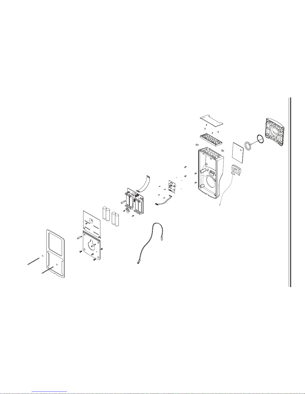
DUAL VALIDATION READER (KEYPAD AND MAGNETIC STRIPE)
Dual validation reader (keypad and magnetic stripe escutcheon) assembly exploded view
Figure 6.2 Dual validation reader (keypad and magnetic stripe) escutcheon assembly (WAMS shown)
+
+
+
-
+
-
-
-
1
2
3
5
6
7
8
11
10
12
14
13
15
4
9
16
17
18
19
3
20
21
22
23
24
25
26
27
28
29
3
Page 73

Wall Mount System Components
Dual validation
reader (keypad and
magnetic stripe)
escutcheon
assembly parts list
Refer to Figure 6.2 and the table below to find the part you need.
WAMS
Item Qty.
Part No.
1 1 B82267 B82267 Housing gasket
2 1 A82271 A82271 Battery cover
3 7 A82245 A82245 Escutcheon assembly screw
4 1 B82548 B82548 Wall mounting plate
5 4 B82272 B82272 Mounting plate screw
6 2 A82557 A82557 Hollow wall anchor
7 2 A82332 A82332 self tapping screw or
not shown
2 A82549 A82549 Masonry anchor screw
8 1 A82556 A82556 Wire assembly
9 1 A82553 A82553 Cable clamp
10 1 B82551 B82551 Wire relay assembly
11 1 A82555 A82555 Nut
12 1 A82265 A82265 Set of 4 batteries (AA alkaline, 1.5V)
13 1 A82086 A82086 Battery cover standoff
14 1 3064470 3061490 Circuit board
15 1 A82249 A82249 Reader cable assembly
16 A82210 A82210 Magnetic head spring
17 A82205 A82205 Magnetic head retaining ring
18 1 B82228 B82228 Magnetic head assembly
19 A82207 A82207 Magnetic head pivot pin
20 1 B82227 B82227 Reader housing
21 1 A82202 A82202 Left bezel spring
22 1 A82201 A82201 Right bezel spring
23 1 B82546 B82546 Keypad assembly
24 4 A82206 A82206 Keyboard mounting screw
25 1 B82242 B82242 Set of keypad keys
26 1 B82229 B82229 Keypad bezel
27 1 A82208 A82208 Magnetic head pin
28 1 3064554 — Antenna assembly
not shown
1 — B82243 IR window
29 1 B82222 B82222 Front cover
2000 Series
Part No. Description
a
(#4–40 × 1/4″ Phillips pan head)
(#8–32 × 3/8″ Phillips flat head)
b
c
d
(#4–40 × 1/4″ Phillips flat head)
d
d
a. For the part number for extreme weatherized battery covers, see Extreme weatherized
b. For the part numbers for weatherized batteries, see Weatherized components on
c. For the part numbers for weatherized circuit boards, see Weatherized components on
d. Specify finish (gray, black, or satin chrome).
Stanley OMNILOCK Illustrated Parts Catalog 6–5
escutcheon components on page 6–9
page 6–8. For best performance, use Duracell or Energizer batteries.
page 6–8. For part numbers for extreme weatherized circuit boards, see Extreme
weatherized escutcheon components on page 6–9
Page 74

Wall Mount System Components
6–6 Stanley OMNILOCK Illustrated Parts Catalog
DUAL VALIDATION READER (KEYPAD AND PROXIMITY)
Dual validation reader (keypad and proximity) escutcheon assembly exploded view
Figure 6.3 Dual validation reader (keypad and proximity) escutcheon assembly (WAMS shown)
+
+
+
-
+
-
-
-
1
2
3
5
6
7
8
11
10
12
14
13
15
4
9
3
16
17
18
19
20
3
21
22
23
24
25
26
27
28
29
30
31
Page 75

Wall Mount System Components
Dual validation
reader (keypad and
proximity)
escutcheon
assembly parts list
Refer to Figure 6.3 and the table below to find the part you need.
WAMS
Item Qty.
Part No.
1 1 B82267 B82267 Housing gasket
2 1 A82271 A82271 Battery cover
3 7 A82245 A82245 Escutcheon assembly screw
4 1 B82548 B82548 Wall mounting plate
5 4 B82272 B82272 Mounting plate screw
6 2 A82557 A82557 Hollow wall anchor
7 2 A82332 A82332 self tapping screw or
not shown
2 A82549 A82549 Masonry anchor screw
8 1 A82556 A82556 Wire assembly
9 1 A82553 A82553 Cable clamp
10 1 B82551 B82551 Wire relay assembly
11 1 A82555 A82555 Nut
12 1 A82265 A82265 Set of 4 batteries (AA alkaline, 1.5V)
13 1 A82086 A82086 Battery cover standoff
14 1 3064470 3061490 Circuit board
15 1 A82249 A82249 Reader cable assembly
16 1 3062138 3062138 Proximity reader cable assembly
17 4 A82224 A82224 Proximity reader circuit board screw
18 1 3062096 3062096 Proximity reader circuit board
19 4 A82225 A82225 Spacer
20 1 B82203 B82203 Proximity reader housing
21 1 A82202 A82202 Left bezel spring
22 1 A82201 A82201 Right bezel spring
23 1 B82546 B82546 Keypad assembly
24 4 A82206 A82206 Keyboard mounting screw
25 1 B82242 B82242 Set of keypad keys
26 1 B82229 B82229 Keypad bezel
27 1 3064554 — Antenna assembly
not shown
1 — B82243 IR window
28 1 A82291 A82291 Cover gasket
29 1 3062337 2062337 Clear tubing
30 1 B82293 B82293 Proximity reader antenna
31 1 B82223 B82223 Front cover
2000 Series
Part No. Description
a
(#4–40 × 1/4″ Phillips pan head)
(#8–32 × 3/8″ Phillips flat head)
b
c
(#2-56 Phillips pan head)
d
(#4–40 × 1/4″ Phillips flat head)
d
d
a. For the part number for extreme weatherized battery covers, see Extreme weatherized
b. For the part numbers for weatherized batteries, see Weatherized components on
c. For the part numbers for weatherized circuit boards, see Weatherized components on
d. Specify finish (gray, black, or satin chrome).
Stanley OMNILOCK Illustrated Parts Catalog 6–7
escutcheon components on page 6–9.
page 6–8. For best performance, use Duracell or Energizer batteries.
page 6–8. For part numbers for extreme weatherized circuit boards, see Extreme
weatherized escutcheon components on page 6–9.
Page 76

Wall Mount System Components
12
WEATHERIZED COMPONENTS
Figure 6.4 Weatherized components
Weatherized
components parts
list
Weatherized escutcheon assemblies include all of the components
listed for the corresponding standard escutcheon assembly except for
the battery pack and circuit board. Refer to Figure 6.4 and the table
below to find the part you need.
WAMS
Item Qty.
1 2 3092031 3092031 3092031 Weatherized battery pack
2 1 3103378 3092005 3109736 Weatherized circuit board
a. The weatherized circuit board is not sold individually. It is provided with weatherized
housing assemblies.
Part No.
2000 Series
Part No.
500 Series
Part No. Description
(alkaline 3V)
a
6–8 Stanley OMNILOCK Illustrated Parts Catalog
Page 77

Wall Mount System Components
Stanley OMNILOCK Illustrated Parts Catalog 6–9
EXTREME WEATHERIZED ESCUTCHEON COMPONENTS
Extreme weatherized escutcheon components exploded view
Figure 6.5 Extreme weatherized escutcheon components
OSI
O
S
I
SECURITY
S
E
CU
R
I
TY
DEVICES
D
E
V
I
C
E
S
INC.2002
I
N
C
.
2
0
02
ASSY
A
S
S
Y
11897-
11
8
9
7
-
REV
R
EV
BT1
BT1
PCB 11897
PCB
11897
REV A
REV
A
BT3
B
T
3
NAL
NA
L
BT2
B
T
2
P1
P
1
RESET/
R
ES
ET
/
MEM
M
E
M
CLEAR
C
L
E
A
R
S1
S
1
+
-
-
+
-
+
-
+
4
6
3
5
7
9
10
11
12
11
8
1
2
Outside of door
Inside of door
Page 78

Wall Mount System Components
Extreme
weatherized
escutcheon
parts list
The extreme weatherized option is available for OMNILOCK 500 Series
and 2000 Series Locks. Extreme weatherized escutcheon assemblies
include all of the components listed for the corresponding standard
escutcheon assembly except for the battery cover and circuit board.
They also include the additional components listed below. Refer to
Figure 6.5 and the table below to find the part you need
2000 Series
Item Qty.
1 1 3108334 3107901 Weatherized circuit board
2 1 B82856 B82856 Weatherized reader battery cover
3 4 A82245 A82245 Screw (#4–40 × 1/4″ Phillips pan head)
4 1 B82849 B82849 Housing cover
5 1 A82269 A82269 Foam pad
6 1 A82265 A82265 Set of 4 batteries (AA alkaline, 1.5V)
7 1 3092430 3092430 Interconnecting circuit board
8 1 B82848 B82848 Housing
9 1 A82487 A83017 Wire assembly
10 1 B82551 B82551 Wire relay assembly
Part No.
500 Series
Part No. Description
a
11 2 A82555 A82555 Nut
12 1 A82553 A82553 Nylon cable clamp
not shown
not shown
not shown
a. The weatherized circuit board is not sold individually. It is provided with weatherized
housing assemblies.
6 A82557 A82557 Hollow wall anchor
6 A82332 A82332 Self tapping screw or
6 A82549 A82549 Masonry anchor screw
6–10 Stanley OMNILOCK Illustrated Parts Catalog
Page 79

5E CYLINDER COMPONENTS
12 3
45
Figure 6.6 5E cylinder components for wall mount systems
Wall Mount System Components
5E cylinder
components list
Refer to Figure 6.6 and the table below to find the part you need.
Item Qty. Part No. Description
1 1 3115797 5E cylinder
2 1 B82558 Collar
3 1 A82559 Spring wave washer
4 2 A82245 Screw (#4–40 × 1/4″ Phillips pan head)
5 1 B82560 Tailpiece
a. Cylinders are keyed alike and come with two operating keys.
a
Stanley OMNILOCK Illustrated Parts Catalog 6–11
Page 80

Wall Mount System Components
6–12 Stanley OMNILOCK Illustrated Parts Catalog
Page 81

7
OTHER COMPONENTS
This chapter provides diagrams and part numbers for
the following OMNILOCK items:
■ programming devices and readers
■ wireless components including single door
controllers, portal gateways, power-over-ethernet
devices, transformers, modems, and antenna kits
■ replacement battery packs
■ service tools.
Stanley OMNILOCK Illustrated Parts Catalog 7–1
Page 82

Other Components
Track 2 magnetic card reader
Proximity card
enrollment reader
Track 1-2-3 magnetic stripe
card encoder / decoder
PROGRAMMING DEVICES, READERS, AND ACCESS CARDS
2000 Series
management
software
WAMS management
software
Refer to the table below to find the part you need.
Nomenclature Description
OMS–11278 Administrator's Kit for OM2000 Magnetic Card Systemsa
OMS–11628 Administrator's Kit for OP2000 Proximity Card Systems
OMS–11687 Database Import Utility
a. The System Software (for an approved PDA) supports up to 65,000 users and
65,000 locks per facility. The kit includes the administrator's guide, magnetic stripe
default programming cards, and manager reference cards.
b. The System Software (for an approved PDA) supports up to 65,000 users and
65,000 locks per facility. The kit includes the administrator's guide, proximity
default programming cards, and manager reference cards.
Refer to the table below to find the part you need.
Nomenclature Description
OMS–12418–001 WAMS System Software Kit
a. WAMS System Software (for a PC) supports up to 64 readers with any combination
of portal gateways (65,000 cardholder / ID capacity). The kit includes the
user manual / administrator’s guide, WAMS startup CD, default programming card,
and a blank card for systems without buttons (for Magnetic Stripe and Proximity
readers).
a
b
Card readers and
encoders
Figure 7.1 Card encoders
Card readers and encoders parts list
Refer to Figure 7.1 and the table below to find the part you need.
Nomenclature Description
OMD–11274 Track 2 magnetic card reader
BE-NTDMSR20633BA Track 1-2-3 magnetic stripe card encoder / decoder
OMD–11507–002 Proximity card enrollment reader
7–2 Stanley OMNILOCK Illustrated Parts Catalog
Page 83

WIRELESS COMPONENTS
Single door controller
sign-on keypad
Single door controller with
half wave dipole antenna
Single door
controller
Figure 7.2 Single door controller
Single door controller parts list
Refer to Figure 7.2 and the table below to find the part you need.
Other Components
Portal gateway
Nomenclature Description
OMX–SDC Single door controller with half wave dipole antenna
WQD–WACPAD Single door controller sign-on keypad
Figure 7.3 Portal gateway
Portal gateway parts list
Refer to Figure 7.3 and the table below to find the part you need.
Stanley OMNILOCK Illustrated Parts Catalog 7–3
Nomenclature Description
OMX–12811 Basic portal gateway
Page 84

Other Components
Power-over-ethernet
power supply / inserter
Power-over-ethernet
active splitter with isolation
Power-over-
ethernet devices
Figure 7.4 Power-over-ethernet devices
Transformer
Power-over-ethernet parts list
Refer to Figure 7.4 and the table below to find the part you need.
Nomenclature Description
OMD–12928–001 Power-over-ethernet active splitter with isolation
OMD–12927–001 Power-over-ethernet power supply / inserter
Figure 7.5 Transformer
Transformer parts list
Refer to Figure 7.5 and the table below to find the part you need.
Nomenclature Description
OMD–12827 Plug-in transformer
7–4 Stanley OMNILOCK Illustrated Parts Catalog
Page 85

Modem
Other Components
Figure 7.6 Modem
Modem parts list
Refer to Figure 7.6 and the table below to find the part you need.
Nomenclature Description
OMD–12873–001 Dial-up to ethernet modem with power adapter
Stanley OMNILOCK Illustrated Parts Catalog 7–5
Page 86

Other Components
Exterior omni-directional
mast mount antenna kit
Exterior directional
mast mount antenna kit
Interior directional
wall mount antenna kit
Interior omni-directional
ceiling mount antenna kit
Antenna kits
Figure 7.7 Antenna kits
Antenna kits list
Refer to Figure 7.7 and the table below to find the part you need.
Nomenclature Description
WQD–AEMO Exterior omni-directional mast mount antenna kit
WQD–AEMD Exterior directional mast mount antenna kit
WQD–ACMO Interior omni-directional ceiling mount antenna kit
WQD–AWMD Interior directional wall mount antenna kit
a. Includes antenna, wall and post mounts, and a 20′ cable to connect the antenna to
a single door controller or portal gateway.
b. Includes antenna, wall and post mounts, and a 20′ cable to connect the antenna to
a single door controller or portal gateway.
c. Includes antenna, standard mount, and a 20′ cable to connect the antenna to a
portal gateway.
d. Includes antenna, standard mount, and a 20′ cable to connect the antenna to a
portal gateway.
a
b
c
d
7–6 Stanley OMNILOCK Illustrated Parts Catalog
Page 87

Other Components
Weatherized battery pack OM250 Battery Pack
TORX® T15 wrench
Wireless
conversion kit
BATTERY PACKS
Wireless conversion kit parts list
Refer to the table below to find the part you need.
Nomenclature Description
OMD–12657–01 Non-weatherized conversion kit
TOOLS
Figure 7.8 Battery pack
Battery packs parts list
Refer to Figure 7.8 and the table below to find the part you need.
Nomenclature Description
OMD–12000 Weatherized battery pack (alkaline 3V)
OMD-6610 OM250 lithium battery pack
Figure 7.9 Tools
Tools parts list
Refer to Figure 7.9 and the table below to find the part you need.
Part No. Description
A82790 TORX® T15 wrench
Stanley OMNILOCK Illustrated Parts Catalog 7–7
Page 88

Other Components
SITE SURVEY KIT AND BEACONS
Figure 7.10 Site survey kit and beacons components
Site survey kit and beacons parts list
Refer to Figure 7.10 and the table below to find the part you need.
Nomenclature or
Part No. Description
OMD–SURVEY Site survey kit with 3 beacons
C82310 Site survey kit without beacons
3112597 Set of three wireless beacons
C83010 Single wireless beacon
7–8 Stanley OMNILOCK Illustrated Parts Catalog
Page 89

A
GLOSSARY
Armored front The mortise lock front and faceplate designed to prevent
tampering with the cylinder clamp screw and case
mounting screws.
Backset The distance from the faceplate to the center of the
cylinder or lever.
Cam See Cylinder cam.
Card reader A device that reads the information encoded on magnetic
stripe cards or proximity cards.
Core See Interchangeable core.
Cylinder See Mortise cylinder.
Cylinder cam A rotating part of a keyed cylinder that drives the
deadbolt or latchbolt.
Stanley OMNILOCK Illustrated Parts Catalog A–1
Cylinder ring A metal ring that fits around the cylinder and protects it
from tampering. The cylinder ring also spaces the
cylinder out to the right position.
Door bevel The angle on the edge of a door.
Door status
sensor
Escutcheon A surface-mounted plate that covers holes that were made
Faceplate A finished part of a mortise lock that covers the armored
Figure-8 The basic shape of the interchangeable core and its
A sensor that monitors whether the door is open or
closed. This sensor is used to detect a forced entry, or a
door that is propped open.
in the door for levers and cylinders.
front. See Armored front.
housing (door lever, cylinder, padlock, and so forth.). See
also Interchangeable core.
Page 90

Glossary
Fob A small device that can be carried on a key ring, has an integrated circuit to
which data is encoded, and is used to activate a lock.
Hand of door The swing direction of the door as viewed from the outside of the door. A
right-handed (RH) door is hinged on the right and swings inward. A lefthanded (LH) door is hinged on the left and swings inward. If either of these
doors swings outward, it becomes a right-hand reverse bevel (RHRB) door, or
a left-hand reverse bevel (LHRB) door respectively.
Interchangeable
core
A figure-8 shaped device that contains all mechanical parts for a masterkeyed
system. The interchangeable core can be removed by a special control key and
can be recombinated without disassembling the lock. See also Figure-8.
Key override An optional feature that enables an authorized user (in an emergency) to
bypass all electronic locking features, and open the lock with a mechanical
key.
Latch status
sensor
A sensor that monitors whether the latchbolt is extended or retracted. This
sensor can be used in combination with the door status sensor to determine
whether the door is fully secure.
Lock function The way a lock operates.
Magnetic stripe
card
A credit-card shaped device that has a magnetic strip to which data is encoded
and is used to access a lock.
Mortise cylinder A threaded lock cylinder that screws directly into the lock case. A key-driven
rotating cam, attached to the back, drives the locking mechanism.
Mortise A rectangular cavity cut into the edge of a door. Also can mean the act of
making such a cavity.
Mortise lock A lock that fits into a mortise. Other locks fit into bored holes or mount to a
surface. See also Mortise.
Proximity card A credit-card shaped device that has an integrated circuit to which data is
encoded and is used to activate a lock.
Removable core See Interchangeable core.
Request-to-exit
switch
A switch that allows the user to exit without setting off an alarm. WAMS Locks
can be supplied with an internal request-to-exit switch. Turning the inside
lever actuates the switch and, when wired to an alarm system, sends a signal
to disable or sound an alarm, start a timer, and so forth.
Tailpiece A part that extends from the back of the cylinder and engages an exit device
mechanism.
Temp la te A precise, detailed hole pattern that serves as a guide for the mortising and
drilling of doors and frames.
Wire harness A group of wires bundled together with connectors at either end.
A–2 Stanley OMNILOCK Illustrated Parts Catalog
 Loading...