

Page 1
Please read these instructions before operating the product
MultiLine
5 - Beam Self-Leveling Multi-Line Laser
77-122
Self-Leveling
GB
D
F
I
E
PT
NL
DK
SE
FIN
NO
PL
GR
CZ
RU
HU
SK
SI
BG
RO
EE
LV
TR
LT
HR
Page 2
2
77-122
Carefully read the Safety Instructions and User Manual before using this product. The person
responsible for the instrument must ensure that all users understand and adhere to these
instructions.
Retain this manual for future reference.
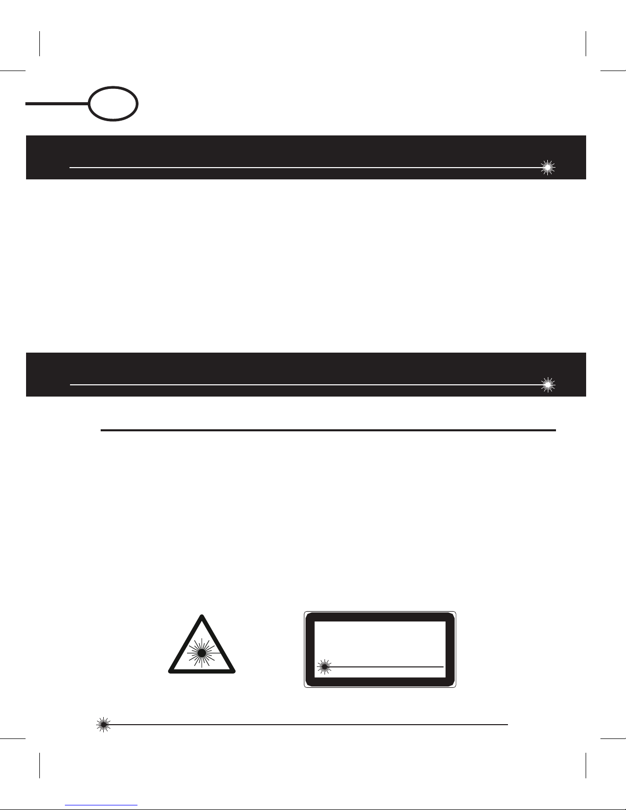
IMPORTANT: The following labels are on your laser tool for your convenience and safety.
They indicate where the laser light is emitted by the level. ALWAYS BE AWARE of their
location when using the level.
1. Safety
2. Product Description
3. Specifications
4. Operating Instructions
5. Calibration
6. Maintenance and Care
7. Warranty
User Safety
Safety
Contents
EN 60825-1
LASER RADIAT IO N - D O NO T
STA RE I NT O BE AM O R VI EW
DIRECTLY W IT H
OPTICAL INSTRUMENTS
CLASS 1M LASER PRODUCT
MA X O UTPUT ≤ 1 m W @ 6 30 - 670 nm
GB
GB
GB
GB ENGLISH
Page 3

3
77-122
DO NOT remove any warning label(s) on the housing. This instrument must only be used for
leveling and layout tasks as outlined in this manual.
ALWAYS make sure that any bystanders in the vicinity of use are made aware of the
dangers of looking directly into the laser tool.
DO NOT use in combination with other optical instruments. Do not modify the instrument, or
make manipulations or use in other applications than those described in the manual.
DO NOT look into the beam with optical aids, such as magnifiers, binoculars or Telescopes.
DO NOT stare into the laser beam or direct it towards other persons. Make sure the
instrument is not set at eye level. Eye protection is normally afforded by natural aversion
responses such as the blink reflex.
DO NOT direct the laser beam at other persons.
ALWAYS turn the laser tool “OFF” when not in use. Leaving the laser tool “ON” increases
the risk of someone inadvertently staring into the laser beam.
DO NOT operate the laser tool in combustible areas such as in the presence of flammable
liquids, gases or dust.
DO NOT disassemble the laser tool. There are no user serviceable parts inside.
Disassembling the laser will void all warranties on the product. Do not modify the product in
any way. Modifying the laser tool may result in hazardous laser radiation exposure.
DO NOT use this instrument in areas where a risk of explosion is present.
NOTE: Since the laser beam is of the focused type, ensure you check the beam’s path over
a relatively long distance and take all necessary precautions to ensure the beam cannot
interfere with other persons.
Page 4
4
77-122
WARNING: Batteries can explode or leak and can cause injury or fire. To reduce this risk:
ALWAYS follow all instructions and warnings on the battery label and package.
DO NOT short any battery terminals
DO NOT charge alkaline batteries.
DO NOT mix old and new batteries. Replace all of them at the same time with new batteries
of the same brand and type.
DO NOT mix battery chemistries.
DO NOT dispose of batteries in fire.
ALWAYS keep batteries out of reach of children.
ALWAYS remove batteries if the device will not be used for several months.
NOTE: Ensure that the correct batteries as recommended are used.
NOTE: Ensure the batteries are inserted in the correct manner, with the correct polarity.
DO NOT dispose of this product with household waste.
ALWAYS dispose of batteries per local code.
PLEASE RECYCLE in line with local provisions for the collection and disposal of electrical
and electronic waste under the WEEE Directive.
Battery Safety
End of Life
Page 5
5
77-122
ROHS Compliant
The Stanley Works declares that the CE Mark has been applied to this
product in accordance with the CE Marking Directive 93/68/EEC.
This product conforms with EN60825-1:2007.
For further details please refer to www.stanleyworks.com.
Declaration of Conformity
Product Description
Package Contents
1. Laser Unit
2. IR Remote Controller
3. Laser Target
4. Glasses
5. Carrying Case
6. Batteries (Laser Unit - 4 x AA, IR Remote Controller - 2 x AA)
7. User Manual
EN 60825-1
Page 6
6
77-122
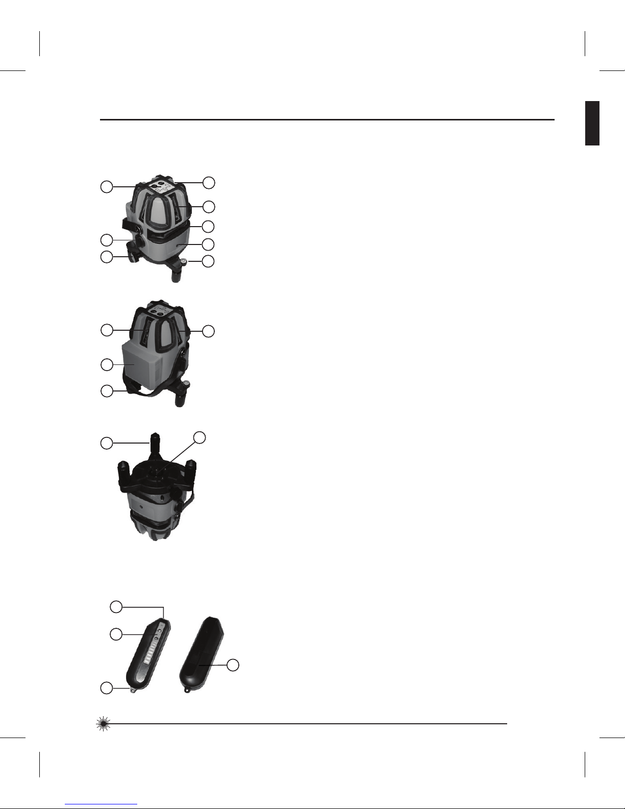
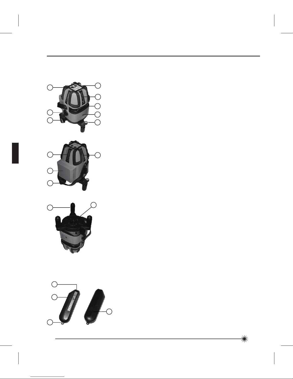
Product Overview
1. Keyboard
2. Main Power / Transport Lock
3. Fine Tuning Wheel
4. Window for 90° Vertical Reference Beam Laser
5. Window for Front Vertical Beam Laser
6. Window for Horizontal Beam Laser
7. IR Sensor
8. Bubble Level
9. Window for Rear Vertical Beam Laser
10. Laser Warning Label
Battery Compartment Cover
11. Handle
12. Window for 90° Vertical Reference Beam Laser
Laser Unit
13. Adjustable Legs 3x
14. 5/8 - 11 Threaded Mount
Window for Down Beam Laser
IR Remote Controller
14
13
1. IR LED
2. Keyboard
3. Location for Lanyard
4. Battery Compartment Cover
12
9
10
11
2
4
1
3
5
4
1
6
8
2
3
7
Page 7

7
77-122
Leveling Accuracy:
Down Beam Accuracy:
Square Beam Accuracy:
Horizontal / Vertical Accurracy
Working Range:
Working Distance:
with Laser Detector:
Laser Class:
Laser Wavelength:
Operating Time:
Power Voltage:
Power Supply:
IP Rating:
Operating Temperature Range:
Storage Temperature Range:
Weight (without Base and Batteries):
≤ 2 mm / 10 m (≤ 5/64 in / 30 ft)
≤ 1 mm / 1.5 m (≤ 1/32 in / 5 ft)
≤ 1 mm / 5 m (≤ 1/32 in / 15 ft)
≤ 2 mm / 10 m (≤ 5/64 in / 30 ft)
Self-Leveling to ± 3°
≤ 15 m (≤ 50 ft)
≤ 50 m (≤ 165 ft)
Class 1M
635 nm ± 5 nm
6 h
6 V
4 x AA Batteries (Alkaline)
IP54
-10° C to +40° C (+14° F to +104° F)
-20° C to +60° C (-4° F to +140° F)
980 g (34,5 oz)
Specifications
Laser Unit
Page 8

8
77-122
110 mm × 105 mm × 180 mm
(4 5/16 in × 4 1/8 in × 7 1/16 in)
Size:
IR Remote Controller
3 V
2 x AA Batteries (Alkaline)
37 g (1,3 oz)
35 mm × 25 mm × 120 mm
(1 3/8 in × 1 in × 4 3/4 in)
Power Voltage:
Power Supply:
Weight (without Batteries):
Size:
Page 9
9
77-122
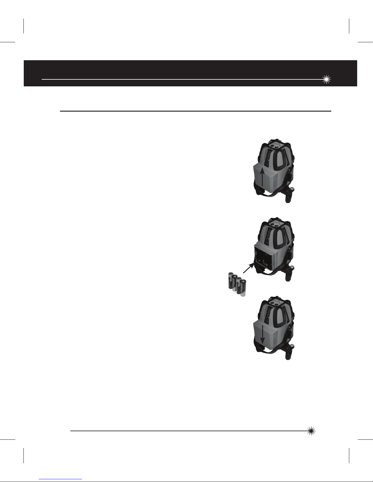
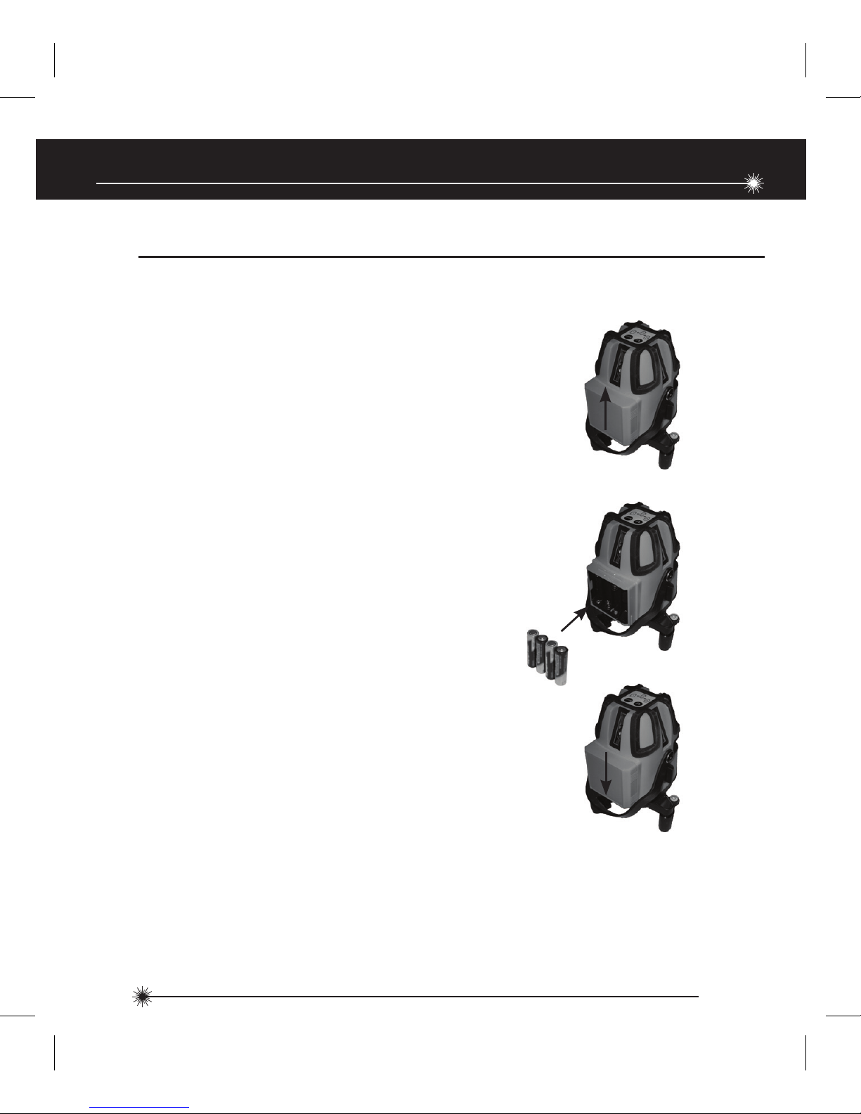
Operating Instructions
1. Turn laser unit to back. Open battery
compartment cover by pressing and sliding
out.
2. Install / Remove batteries. Orient batteries
correctly when placing into laser unit.
3. Close and lock battery compartment cover
by sliding in until securely closed.
+
+
+
-
-
-
+
-
Laser Unit
Battery Installation / Removal
Page 10
10
77-122
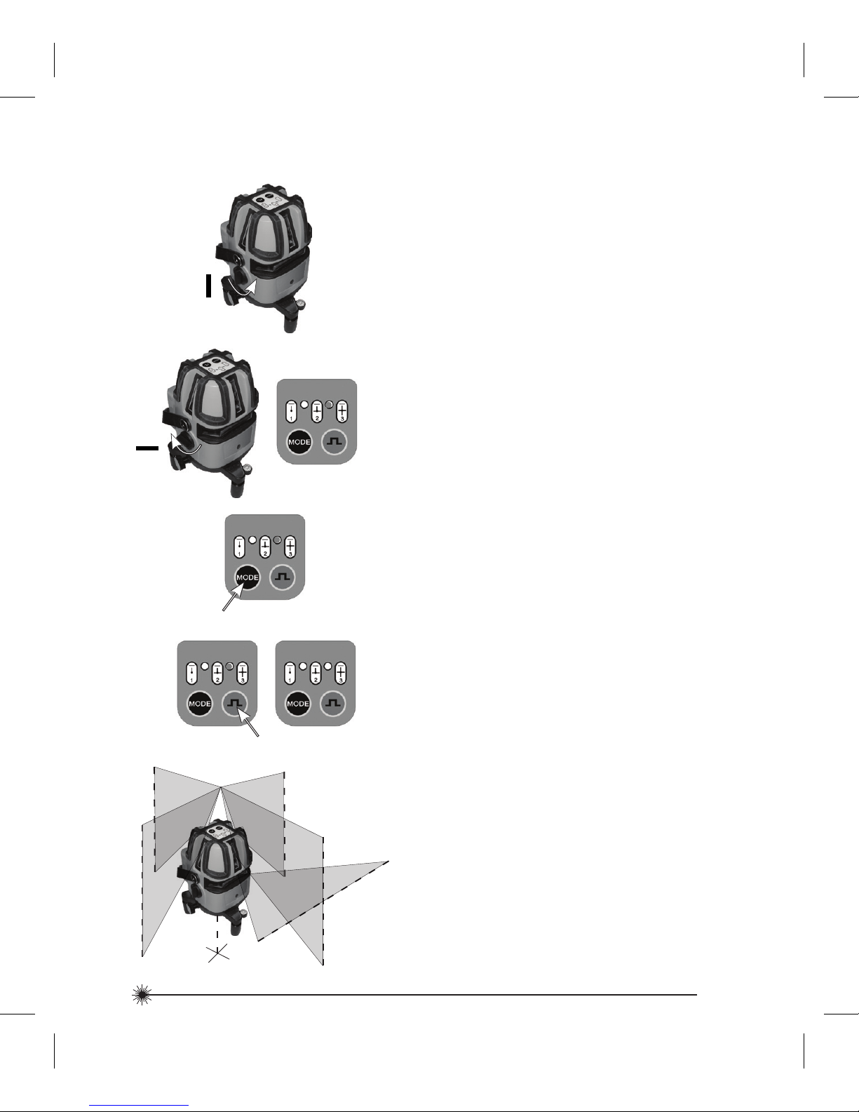
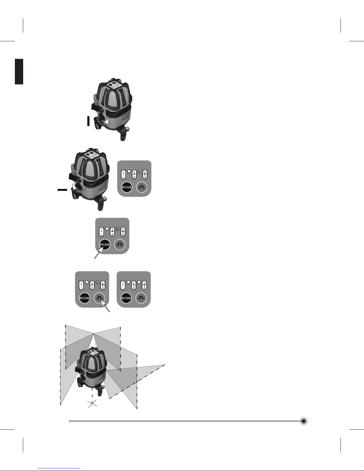
4. Press pulse mode key to toggle between
pulse mode ON and OFF. Indicator LED lights
green when on. Pulse mode allows use with
a laser detector.
2. Transport lock in unlocked position. Laser
power is ON. Down laser beam and
horizontal laser beam turn on. Left LED
indicator lights green when laser power is
on.
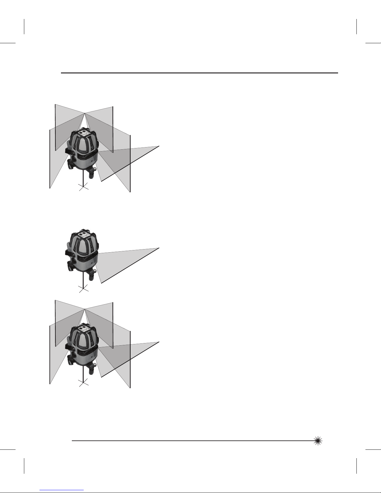
3. Press laser mode key to toggle through
available laser modes - horizontal only,
both horizontal and vertical, horizontal and
vertical with left and right 90° vertical
reference beam, horizontal with all 4 vertical.
1. Transport lock in locked position. Laser
power is OFF.
5. Laser beam(s) blink to indicate the laser unit
is out of the working range. Reposition laser
unit to be more level.
Pulse Mode
Function
Laser Mode
Unlocked
Locked
Page 11

11
77-122
8. Low battery - Left LED blinks red to indicate
when battery power is low. Replace
batteries.
Standard Mount for
Optional Tripod Mounting
5/8 in
3. 5/8 - 11 thread mount available for optional
accessories.
Laser Unit Base
1. Turn any of the adjustable legs as needed to
level the laser unit within its workable range.
Use the bubble vial for reference.
2. Use fine adjustment wheel to gradually
rotate the projection of the laser beam(s).
3x
Bubble Vial
Page 12
12
77-122
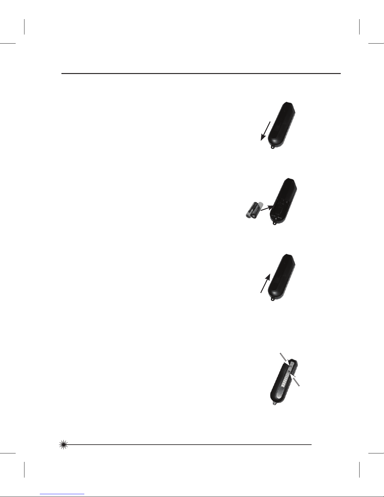
IR Remote Controller
Battery Installation / Removal
1. Turn laser unit to back. Open battery
compartment cover by pressing and sliding
out.
2. Install / Remove batteries. Orient batteries
correctly when placing into laser unit.
3. Close and lock battery compartment cover
by sliding in until securely closed.
+
+ -
-
Function
1. Aim remote controller towards laser unit
and press laser mode key to toggle through
available laser modes.
2. Press pulse mode key to toggle between
pulse mode ON and OFF.
Laser Mode
Pulse Mode
Page 13
13
77-122
Applications
1. Plumb:
Using the vertical laser beam, establish a
vertical reference plane. Position the desired
object(s) until they are aligned with the
vertical reference plane to ensure object(s)
are plumb.
Establish 2 reference points that need to be
plumb. Align either the down laser beam or
the up laser cross to a set reference point.
The opposing laser beam(s) will be projecting
a point which is plumb. Position the desired
object until the laser beam is aligned with
the second reference point that needs to be
plumb with the set reference point.
2. Level:
Using the horizontal laser beam, establish
a horizontal reference plane. Position the
desired object(s) until they are aligned with
the horizontal reference plane to ensure
object(s) are level.
3. Square:
Using either the vertical and horizontal
laser beams with or without the 90° vertical
reference laser beam, establish a point
where the vertical and horizontal beams
cross. Position the desired object(s) until
they are aligned with both the vertical and
horizontal laser beams to ensure object(s)
are square.
4. Pulse Mode:
Setting laser unit to pulse mode allows use
of optional laser detectors.
Page 14
14
77-122
Calibration
NOTE: The laser unit has been calibrated at the time of manufacturing. Periodically check
the accuracy of the laser unit to ensure that the calibrated specifications are maintained.
P
1
D
1
D
1
2
P
2
P
1
D
1
D
1
2
P
3
P
1
P
2
D
2
P
4
P
1
P
2
P
3
D
2
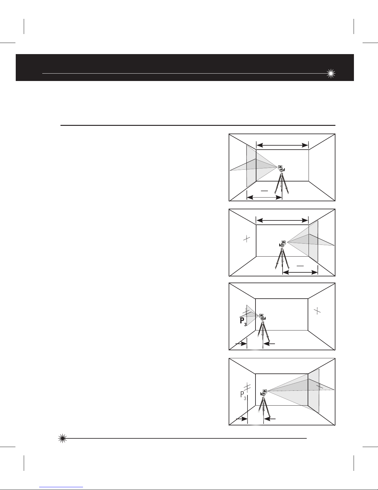
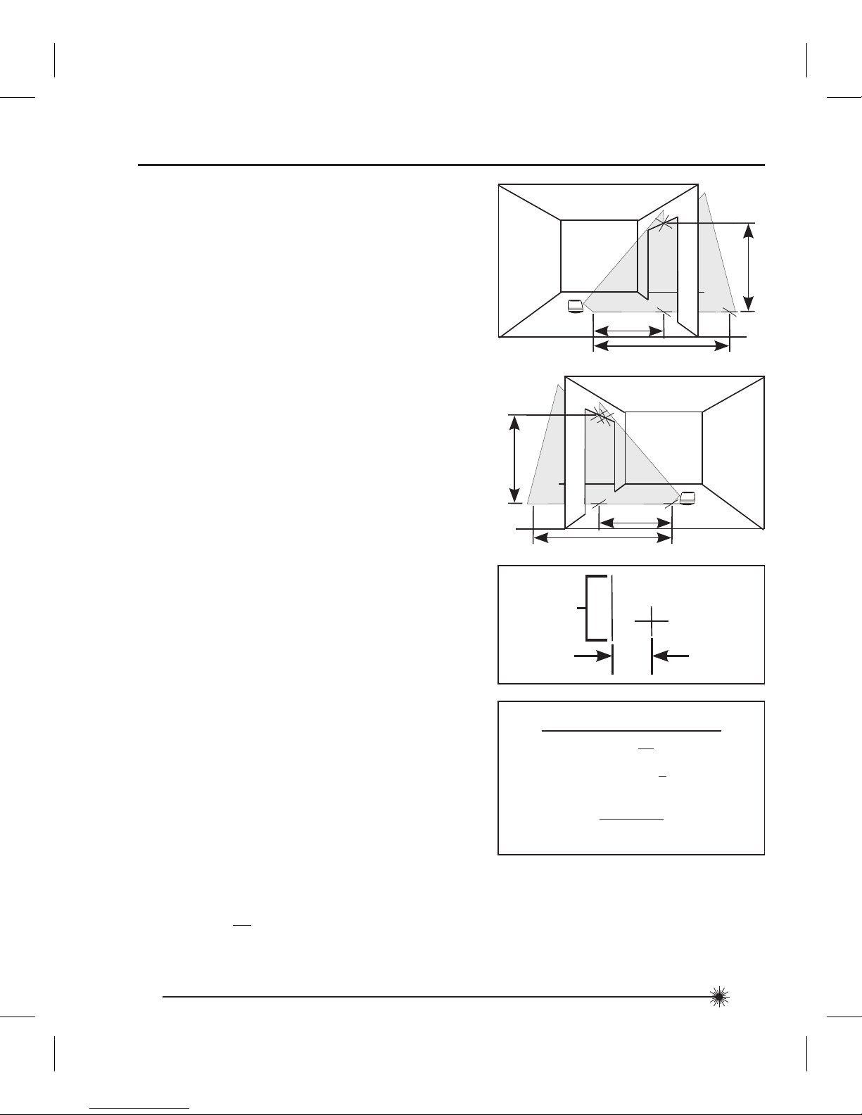
1. Place laser unit as shown with laser ON.
Mark point P1 at cross.
Level Beam Accuracy
2. Rotate laser unit 180° and mark point P2
at cross.
3. Move laser unit close to wall and mark
point P3 at cross.
4. Rotate laser unit 180° and mark point P4
at cross.
Page 15
15
77-122
5. Measure the vertical distance from
the floor to each point. Calculate the
difference between distances D
P1
and DP3
to get D3 and distances DP2 and DP4 to get
D4 .
6. Calculate the maximum allowed offset
distance and compare to the difference
of D3 and D4 as shown in the equation. If
the sum is not less than or equal to the
calculated maximum offset distance the
unit must be returned to your Stanley
Distributor.
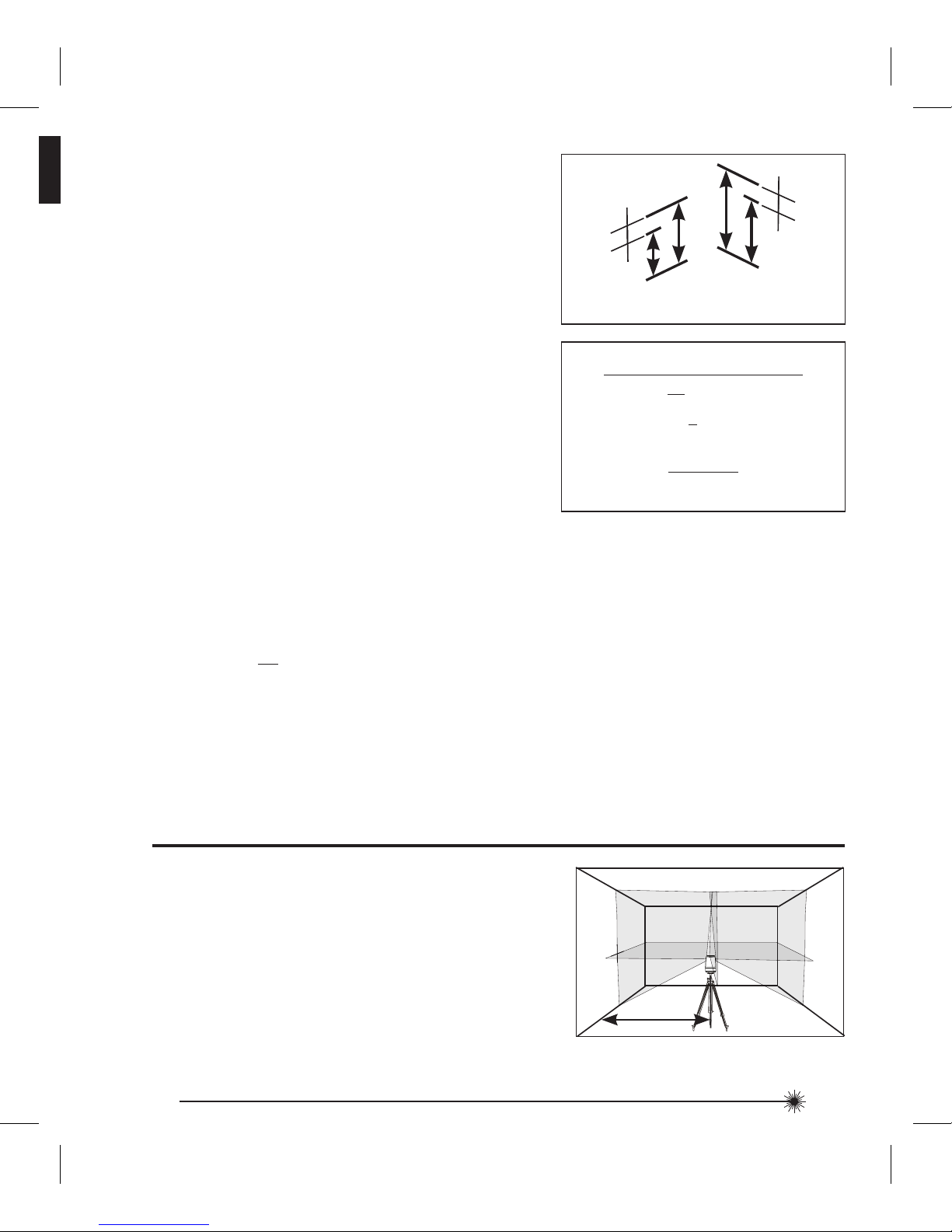
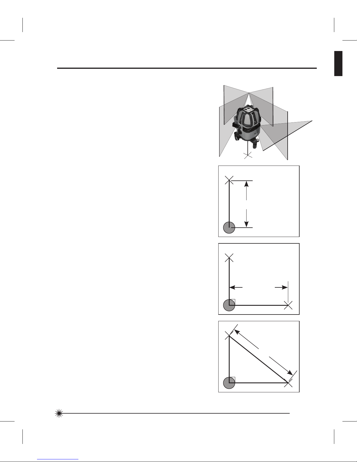
1. Place laser unit as shown with horizontal,
vertical, and both 90° vertical reference
laser beams ON. Mark point P1 where the
horizontal and left 90° vertical reference
laser beams cross.
Horizontal Beam Accuracy
P
1
D
1
P
3
P
1
D
P3
D
P1
(DP1 - DP3 ) = D
3
P
4
P
2
D
P2
D
P4
(DP2 - DP4 ) = D
4
Example: D1 = 10 m, D2 = 0,5 m
DP1 = 30,75 mm, D
P2
= 29 mm, DP3 = 30 mm, D
P4
= 29,75 mm
D3 = (30,75 mm - 30 mm) = 0,75 mm
D4 = (29 mm - 29,75 mm) = - 0,75 mm
0,2 x (10 m - (2 x 0,5 m) = 1,8 mm (maximum allowed offset distance)
(0,75 mm) - (- 0,75 mm) = 1,5 mm
1,5 mm ≤ 1,8 mm (TRUE, unit is within calibration)
mm
m
Compare:
D3 - D4 ≤
± Max
Maximum Offset Distance:
Max
in
ft
= 0,0024 x (D1 ft - (2 x D2 ft))
mm
m
= 0,2 x (D1 m - (2 x D2 m))
Page 16
16
77-122
Example: D1 = 5 m, D2 = 1 mm
0,2 x 5 m = 1 mm (maximum allowed offset distance)
1 mm ≤ 1 mm (TRUE, unit is within calibration)
mm
m
2. Rotate laser unit 90° and align front
vertical laser beam with point P1 . Mark
point P2 where the horizontal and front
vertical laser beams cross.
3. Rotate laser unit 90° and align right 90°
vertical reference laser beam with point
P1 . Mark point P3 where the horizontal and
right 90° vertical reference laser beams
cross.
4. Measure the vertical distance D2 between
the highest and lowest point
.
P
2
D
1
P
1
P
2
D
1
P
1
P
3
P
2
D
2
P
1
P
3
5. Calculate the maximum allowed offset
distance and compare to D2 . If D2 is
not less than or equal to the calculated
maximum offset distance the unit must be
returned to your Stanley Distributor.
Compare:
D2 ≤
Max
Maximum Offset Distance:
Max
in
ft
= 0,0024 x D1 ft
mm
m
= 0,2 x D1 m
Page 17
17
77-122
Vertical Beam Accuracy
P
1
D
1
P
2
P
3
D
1
2 x D
1
P
4
D
1
P
2
P
3
D
1
2 x D
1
P
1
1. Measure the height of a door jamb or
reference point to get distance D1 . Place
laser unit as shown with laser ON. Aim
vertical beam towards door jamb or
reference point. Mark points P1 , P2 , and
P3 as shown.
Example: D1 = 2 m, D2 = 0,5 mm
0,4 x 2 m = 0,8 mm (maximum allowed offset distance)
0,5 mm ≤ 0,8 mm (TRUE, unit is within calibration)
mm
m
2. Move laser unit to opposite side of door
jamb or reference point and align vertical
beam with P2 and P3 .
3. Measure the horizontal distances between
P1 and the vertical beam from the 2nd
location.
4. Calculate the maximum allowed offset
distance and compare to D2 . If D2 is
not less than or equal to the calculated
maximum offset distance the unit must be
returned to your Stanley Distributor.
Compare:
D2 ≤
Max
Maximum Offset Distance:
Max
in
ft
= 0,0048 x D1 ft
mm
m
= 0,4 x D1 m
P
1
D
2
Vertical
Beam
Page 18
18
77-122
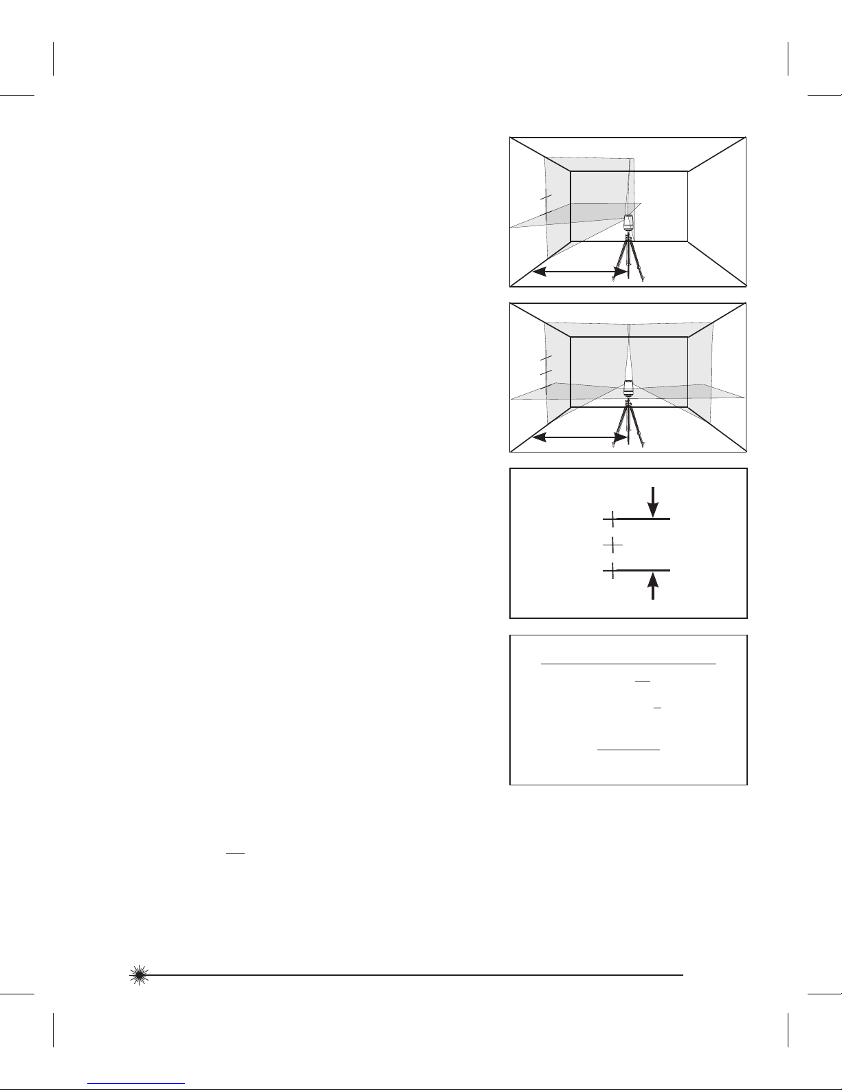
90° Vertical Beam Accuracy
You will need at least 1,5 m2 (16 ft2) of floor space and possibly an assistant for this check.
1. Place the laser unit on a level floor, and
turn on all beams.
2. Measure exactly 0,91 m (3 ft) out from
the center of the laser unit along the front
vertical laser beam. Mark this point P1 .
3. Measure exactly 1,22 m (4 ft) out the
center of the instrument along either of
the 90° vertical reference beams, and
mark this point P2 .
4. Measure from point A to point B; this
distance D1 should equal 1,522 m ± 0,3 mm
(5 ft ± 1/64 in). If not, the unit must be
returned to your Stanley Distributor.
5. Repeat steps 1 through 4 to check the
other beams.
P
1
0,91 m (3 ft)
P
1
1,22 m (4 ft)
P
2
P
1
P
2
D
1
Page 19

19
77-122
Laser unit is not waterproof. DO NOT allow to get wet. Damage to internal circuits may
result.
DO NOT leave laser unit in direct sunlight or expose it to high temperatures. The housing
and some internal parts are made of plastic and may become deformed at high temperatures.
DO NOT store the laser unit in a cold environment. Moisture may form on interior parts
when warming up. This moisture could fog up laser windows and cause corrosion of internal
circuit boards.
When working in dusty locations, some dirt may collect on the laser window. Remove any
moisture or dirt with a soft, dry cloth.
DO NOT use aggressive cleaning agents or solvents.
Store the laser unit in its case when not in use. If storing for extended time, remove batteries
before storage to prevent possible damage to the instrument.
Maintenance and Care
Page 20

20
77-122
One Year Warranty
Stanley Tools warrants its electronic measuring tools against deficiencies in materials and/or
workmanship for one year from date of purchase.
Deficient products will be repaired or replaced, at Stanley Tools’ option, if sent together with
proof of purchase to:
Stanley UK Sales Limited
Gowerton Road
Brackmills, Northampton NN4 7BW
This Warranty does not cover deficiencies caused by accidental damage, wear and tear, use
other than in accordance with the manufacturer’s instructions or repair or alteration of this
product not authorised by Stanley Tools.
Repair or replacement under this Warranty does not affect the expiry date of the Warranty.
To the extent permitted by law, Stanley Tools shall not be liable under this Warranty for
indirect or consequential loss resulting from deficiencies in this product.
This Warranty may not be varied without the authorisation of Stanley Tools.
This Warranty does not affect the statutory rights of consumer purchasers of this product.
This Warranty shall be governed by and construed in accordance with the laws of England
and Stanley Tools and the purchaser each irrevocably agrees to submit to the exclusive
jurisdiction of the courts of England over any claim or matter arising under or in connection
with this Warranty.
IMPORTANT NOTE: The customer is responsible for the correct use and care of the
instrument. Moreover, the customer is completely responsible for periodically checking the
accuracy of the laser unit, and therefore for the calibration of the instrument.
Calibration and care are not covered by warranty.
Subject to change without notice
Warranty
Page 21
21
77-122
Lesen Sie vor der Verwendung dieses Produkts aufmerksam die Sicherheitshinweise und die
Bedienungsanleitung. Die für das Instrument verantwortliche Person muss gewährleisten,
dass sämtliche Benutzer die darin enthaltenen Anweisungen verstehen und befolgen.
Heben Sie diese Bedienungsanleitung auf.
WICHTIG: Die folgenden Etiketten auf Ihrem Lasergerät erleichtern Ihnen die Arbeit und
dienen Ihrer Sicherheit. Sie zeigen an, wo Laserlicht ausgestrahlt wird. Wenn Sie die
Nivellierung benutzen, sollten Sie STETS ihre Position KENNEN.
1. Sicherheit
2. Produktbeschreibung
3. Technische Daten
4. Betriebsanleitung
5. Kalibrierung
6. Wartung und Pflege
7. Gewährleistung
Benutzersicherheit
Sicherheit
Inhaltsverzeichnis
EN 60825-1
LASERSTRAHLUNG - NICHT
IN DEN STRAHL SEHEN ODER
DIREKT MIT OPTISCHEN
INSTRUMENTEN BETRACHTEN
LASERPRODUKT DER KLASSE 1M
MAXIMALE LEISTUNG ≤ 1 mW @ 630 - 670 nm
GB
D
GB
D
GB ENGLISH
GERMAN
D
Page 22

22
77-122
Entfernen Sie KEINE Warnetiketten vom Gehäuse. Dieses Instrument darf nur für die in
dieser Anleitung beschriebenen Nivellier- und Layoutaufgaben verwendet werden.
Sorgen Sie STETS dafür, dass alle Personen in der Nähe des Geräts über die Gefahren bei
direktem Blick in das Lasergerät informiert sind.
NICHT in Kombination mit anderen optischen Instrumenten verwenden. Verändern Sie das
Instrument nicht, manipulieren Sie es nicht und verwenden Sie es für keine Anwendungen,
die nicht in dieser Anleitung beschrieben sind.
Blicken Sie NIEMALS mit optischen Hilfsmitteln wie Lupen, Ferngläsern oder Teleskopen
in den Strahl.
NIEMALS in den Laserstrahl starren oder den Laserstrahl direkt auf andere Personen
richten. Achten Sie darauf, das Instrument nicht auf Augenhöhe aufzustellen. Für gewöhnlich
erfolgt der Augenschutz durch natürliche Schutzreaktionen wie Blinzeln.
Richten Sie den Laserstrahl NIEMALS direkt auf andere Personen.
Schalten Sie das Lasergerät IMMER aus, wenn es nicht verwendet wird. Bei dauerhaft
eingeschaltetem Lasergerät erhöht sich das Risiko, dass jemand unabsichtlich in den
Laserstrahl blickt.
Das Lasergerät darf NICHT in hochgradig brennbaren Umgebungen eingesetzt werden, z.
B. in der Nähe von entflammbaren Flüssigkeiten, Gasen oder Staub.
Zerlegen Sie das Lasergerät NIEMALS. Im Innern befinden sich keine Komponenten, die
vom Benutzer gewartet oder repariert werden könnten. Die Zerlegung des Lasers führt zum
Verfall aller Garantien des Produkts. Das Produkt darf auf keine Weise modifiziert werden.
Durch Modifizieren des Lasergeräts entsteht die Gefahr, sich gefährlicher Laserstrahlung
auszusetzen.
Verwenden Sie dieses Instrument NICHT in Bereichen, in denen Explosionsgefahr
gegeben ist.
HINWEIS: Da es sich um einen gebündelten Laserstrahl handelt, ist der Weg des Lasers
unbedingt über eine relativ lange Strecke zu überprüfen, und es sind sämtliche erforderlichen
Maßnahmen zu ergreifen, um zu gewährleisten, dass der Strahl nicht auf Personen treffen
kann.
Page 23

23
77-122
WARNUNG: Batterien können explodieren oder auslaufen und Verletzungen oder Feuer
verursachen. Folgende Maßnahmen reduzieren dieses Risiko:
Befolgen Sie IMMER sämtliche Anweisungen und Warnhinweise auf der Batterie und ihrer
Verpackung.
Schließen Sie Batterieanschlüsse NIEMALS kurz.
Laden Sie Alkali-Batterien NICHT auf.
Vermischen Sie NICHT alte und neue Batterien. Ersetzen Sie alle gleichzeitig durch neue
Batterien der gleichen Marke und des gleichen Typs.
Vermischen Sie KEINE chemisch unterschiedlichen Batterietypen.
Entsorgen Sie Batterien NICHT durch Verbrennen.
Bewahren Sie Batterien IMMER außerhalb der Reichweite von Kindern auf.
Entfernen Sie IMMER die Batterien, wenn das Gerät über mehrere Monate nicht zum
Einsatz kommt.
HINWEIS: Achten Sie darauf, dass die richtigen, empfohlenen Batterien verwendet werden.
HINWEIS: Achten Sie darauf, dass Batterien richtig ausgerichtet eingelegt werden.
Entsorgen Sie dieses Produkt NICHT im Hausmüll.
Entsorgen Sie Batterien IMMER gemäß den vor
Ort geltenden Bestimmungen.
BITTE UM WIEDERVERWERTUNG gemäß den örtlichen Bestimmungen für die Sammlung
und Entsorgung von Elektro- und Elektronikabfall unter der WEEE-Richtlinie.
Batteriesicherheit
Entsorgung
Page 24
24
77-122
ROHS-kompatibel
Die Stanley Werke erklären, dass die CE-Kennzeichnung auf diesem
Produkt in Übereinstimmung mit der CE-Kennzeichnungsrichtlinie
93/68/EWG angebracht wurde.
Dieses Produkt entspricht EN60825-1:2007.
Für weitere Einzelheiten besuchen Sie bitte
www.stanleyworks.com.
Konformitätserklärung
Produktbeschreibung
Verpackungsinhalt
1. Lasergerät
2. IR-Fernbedienung
3. Laserziel
4. Brille
5. Tragetasche
6. Batterien (Lasergerät - 4 x AA, IR-Fernbedienung - 2 x AA)
7. Bedienungsanleitung
EN 60825-1
Page 25
25
77-122
Produktüberblick
1. Tastenfeld
2. Haupt-Ein-/Ausschalter / Transportsicherung
3. Feinjustierrad
4. Öffnung für vertikalen 90°-Referenzlaser
5. Öffnung für vorderen vertikalen Laser
6. Öffnung für horizontalen Laser
7. IR-Sensor
8. Wasserwaage
9. Öffnung für hinteren vertikalen Laser
10. Laserwarnetikett
Batteriefachabdeckung
11. Griff
12. Öffnung für vertikalen 90°-Referenzlaser
Lasergerät
13. Verstellbare Beine 3x
14. 5/8-11 Anschlussgewinde
Öffnung für Abwärtslaser
IR-Fernbedienung
14
13
1. IR-LED
2. Tastenfeld
3. Anbringung für Trageband
4. Batteriefachabdeckung
12
9
10
11
2
4
1
3
5
4
1
6
8
2
3
7
Page 26

26
77-122
Nivelliergenauigkeit:
Abwärtsstrahlgenauigkeit:
Flächenstrahlgenauigkeit:
Horizontale / Vertikale Genauigkeit
Arbeitsbereich:
Arbeitsentfernung:
mit Laserdetektor:
Laserklasse:
Laserwellenlänge:
Betriebsdauer:
Versorgungsspannung:
Stromversorgung:
IP-Klasse:
Betriebstemperaturbereich:
Lagertemperaturbereich:
Gewicht (ohne Rahmen und
Batterien):
≤ 2 mm / 10 m (≤ 5/64 Zoll / 30 ft)
≤ 1 mm / 1,5 m (≤ 1/32 Zoll / 5 ft)
≤ 1 mm / 5 m (≤ 1/32 Zoll / 15 ft)
≤ 2 mm / 10 m (≤ 5/64 Zoll / 30 ft)
Selbstnivellierung auf ± 3°
≤ 15 m (≤ 50 ft)
≤ 50 m (≤ 165 ft)
Klasse 1M
635 nm ± 5 nm
6 h
6 V
4 x AA Batterien (Alkali)
IP54
-10° C bis +40° C (+14° F bis +104° F)
-20° C bis +60° C (-4° F bis +140° F)
980 g (34,5 oz)
Technische Daten
Lasergerät
Page 27

27
77-122
110 mm × 105 mm × 180 mm
(4 5/16 Zoll × 4 1/8 Zoll × 7 1/16 Zoll)
Größe:
IR-Fernbedienung
3 V
2 x AA Batterien (Alkali)
37 g (1,3 oz)
35 mm × 25 mm × 120 mm
(1 3/8 Zoll × 1 Zoll × 4 3/4 Zoll)
Versorgungsspannung:
Stromversorgung:
Gewicht (ohne Batterien):
Größe:
Page 28
28
77-122
Betriebsanleitung
1. Gerät umdrehen. Batteriefachabdeckung
durch Drücken und Herausschieben öffnen.
2. Batterien einlegen / entfernen.
Batterien beim Einlegen in den Laser
ordnungsgemäß ausrichten.
3. Batteriefachabdeckung durch Schieben bis
zum Einrasten schließen und verriegeln.
+
+
+
-
-
-
+
-
Lasergerät
Einlegen / Entfernen der Batterien
Page 29
29
77-122
4. Impulsmodustaste drücken, um zwischen
Impulsmodus EIN und AUS umzuschalten.
Anzeige-LED leuchtet im eingeschalteten
Zustand grün. Der Impulsmodus ermöglicht
die Verwendung mit einem Laserdetektor.
2. Transportsicherung in entriegelter Position.
Laser ist eingeschaltet. Abwärtslaserstrahl
und horizontaler Laserstrahl schalten sich
ein. Linke LED-Anzeige leuchtet grün, wenn
Laser eingeschaltet ist.
3. Lasermodustaste drücken, um zwischen
verfügbaren Lasermodi umzuschalten - nur
horizontal, sowohl horizontal als auch
vertikal, horizontal und vertikal mit linkem
und rechtem vertikalem 90°-Referenzstrahl,
horizontal mit allen 4 vertikal.
1. Transportsicherung in verriegelter Position.
Laser ist ausgeschaltet.
5. Laserstrahl(en) blinkt/blinken, um
anzuzeigen, dass das Lasergerät sich
außerhalb des Arbeitsbereichs befindet.
Gerät neu positionieren, sodass es ebener
steht.
Impulsmodus
Funktion
Lasermodus
Entriegelt
Verriegelt
Page 30

30
77-122
6. Batterie schwach - Linke LED blinkt rot, um
geringen Batterieladestand anzuzeigen.
Batterien ersetzen.
Standardbefestigung für
optionale Stativmontage
5/8 Zoll
3. 5/8-11 Anschlussgewinde für optionales
Zuberhör.
Lasergerätrahmen
1. Eines oder mehrere der verstellbaren
Beine nach Bedarf drehen, um Lasergerät
innerhalb des Arbeitsbereichs zu nivellieren.
Wasserwaage als Referenz verwenden.
2. Feinjustierrad verwenden, um die Projektion
des Laserstrahls/der Laserstrahlen langsam
zu drehen.
3x
Wasserwaage
Page 31

31
77-122
IR-Fernbedienung
Einlegen / Entfernen der Batterien
1. Gerät umdrehen. Batteriefachabdeckung
durch Drücken und Herausschieben öffnen.
2. Batterien einlegen / entfernen.
Batterien beim Einlegen in den Laser
ordnungsgemäß ausrichten.
3. Batteriefachabdeckung durch Schieben bis
zum Einrasten schließen und verriegeln.
+
+ -
-
Funktion
1. Fernbedienung auf das Lasergerät
richten und Lasermodustaste drücken,
um zwischen den verfügbaren Lasermodi
umzuschalten.
2. Impulsmodustaste drücken, um zwischen
Impulsmodus EIN und AUS umzuschalten.
Lasermodus
Impulsmodus
Page 32

32
77-122
Anwendungen
1. Lot:
Mit dem vertikalen Laserstrahl eine vertikale
Referenzebene einrichten. Position des/der
gewünschten Objekts(e) ändern, bis diese(s) mit der
vertikalen Referenzebene ausgerichtet ist/sind, um zu
gewährleisten, dass das/die Objekt(e) im Lot ist/sind.
2 Referenzpunkte einrichten, die im Lot sein
müssen. Entweder den Abwärtslaserstrahl
oder das Aufwärtslaserkreuz auf einen
festgelegten Referenzpunkt ausrichten. Der/die
gegenüberliegende(n) Laserstrahl(en) projiziert/
projizieren einen Punkt, der im Lot ist. Position des
gewünschten Objekts ändern, bis der Laserstrahl mit
dem zweiten Referenzpunkt ausgerichtet ist, der im
Lot mit dem festgelegten Referenzpunkt sein muss.
2. Nivellierung:
Mit dem horizontalen Laserstrahl eine horizontale
Referenzebene einrichten. Position des/der
gewünschten Objekts(e) ändern, bis diese(s) mit der
horizontalen Referenzebene ausgerichtet ist/sind,
um zu gewährleisten, dass das/die Objekt(e) in der
Waage ist/sind.
3. Rechteck:
Mit den vertikalen und horizontalen Laserstrahlen
mit oder ohne vertikalem 90°-Referenzstrahl
einen Punkt einrichten, an dem sich die vertikalen
und horizontalen Strahlen kreuzen. Position
des/der gewünschten Objekt(e) ändern, bis
diese(s) mit sowohl dem vertikalen als auch dem
horizontalen Laserstrahl ausgerichtet ist/sind, um zu
gewährleisten, dass das/die Objekt(e) rechteckig ist/
sind.
4. Impulsmodus:
Einstellen des Geräts auf Impulsmodus ermöglicht die
Verwendung optionaler Laserdetektoren.
Page 33

33
77-122
Kalibrierung
HINWEIS: Das Lasergerät wurde bei der Herstellung kalibriert. Überprüfen Sie regelmäßig
die Genauigkeit des Lasers, um zu gewährleisten, dass die kalibrierten technischen Werte
immer stimmen.
P
1
D
1
D
1
2
P
2
P
1
D
1
D
1
2
P
3
P
1
P
2
D
2
P
4
P
1
P
2
P
3
D
2
1. Gerät wie abgebildet mit eingeschaltetem
Laser aufstellen. Punkt P1 am Kreuz
markieren.
Nivellierstrahlgenauigkeit
2. Gerät um 180° drehen und Punkt P2 am
Kreuz markieren.
3. Gerät nah an die Wand verschieben und
Punkt P3 am Kreuz markieren.
4. Gerät um 180° drehen und Punkt P4 am
Kreuz markieren.
Page 34

34
77-122
5. Vom Boden zu jedem Punkt vertikale
Entfernung messen. Differenz zwischen
den Entfernungen D
P1
und DP3 berechnen,
um D3 zu erhalten, bzw. zwischen den
Entfernungen DP2 und DP4, um D4 zu
erhalten.
6. Maximal zulässigen Versatz berechnen
und wie in der Gleichung gezeigt mit der
Differenz von D3 und D4 vergleichen. Ist
die Summe größer als der berechnete,
maximal zulässige Versatz, muss das
Gerät an Ihren Stanley-Händler retourniert
werden.
1. Lasergerät wie abgebildet platzieren,
wobei horizontaler, vertikaler und beide
vertikalen 90°-Referenzlaserstrahlen
eingeschaltet sind. Punkt P1 markieren,
an dem sich der horizontale und der linke
vertikale 90°-Referenzlaserstrahl kreuzen.
Horizontale Strahlgenauigkeit
P
1
D
1
P
3
P
1
D
P3
D
P1
(DP1 - DP3 ) = D
3
P
4
P
2
D
P2
D
P4
(DP2 - DP4 ) = D
4
Beispiel: D1 = 10 m, D2 = 0,5 m
DP1 = 30,75 mm, D
P2
= 29 mm, DP3 = 30 mm, D
P4
= 29,75 mm
D3 = (30,75 mm - 30 mm) = 0,75 mm
D4 = (29 mm - 29,75 mm) = - 0,75 mm
0,2 x (10 m - (2 x 0,5 m) = 1,8 mm (maximal zulässiger Versatz)
(0,75 mm) - (- 0,75 mm) = 1,5 mm
1,5 mm ≤ 1,8 mm (WAHR, Gerät ist innerhalb der Kalibrierungstoleranz)
mm
m
Vergleich:
D3 - D4 ≤
± Max
Maximaler Versatz:
Max
Zoll
ft
= 0,0024 x (D1 ft - (2 x D2 ft))
mm
m
= 0,2 x (D1 m - (2 x D2 m))
Page 35

35
77-122
Beispiel: D1 = 5 m, D2 = 1 mm
0,2 x 5 m = 1 mm (maximal zulässiger Versatz)
1 mm ≤ 1 mm (WAHR, Gerät ist innerhalb der Kalibrierungstoleranz)
mm
m
2. Lasergerät um 90° drehen und vorderen
vertikalen Laserstrahl auf Punkt P1
ausrichten. Punkt P2 markieren, an dem
sich der horizontale und vordere vertikale
Laserstrahl kreuzen.
3. Lasergerät um 90° drehen und rechten
vertikalen 90°-Referenzlaserstrahl auf
Punkt P1 ausrichten. Punkt P3 markieren,
an dem sich der horizontale und der rechte
vertikale 90°-Referenzlaserstrahl kreuzen.
4. Vertikale Entfernung D2 zwischen dem
höchsten und tiefsten Punkt messen
.
P
2
D
1
P
1
P
2
D
1
P
1
P
3
P
2
D
2
P
1
P
3
5. Maximal zulässigen Versatz berechnen und
mit D2 vergleichen. Ist D2 größer als der
berechnete, maximal zulässige Versatz,
muss das Gerät an Ihren Stanley-Händler
retourniert werden.
Vergleich:
D2 ≤
Max
Maximaler Versatz:
Max
Zoll
ft
= 0,0024 x D1 ft
mm
m
= 0,2 x D1 m
Page 36

36
77-122
Vertikale Strahlgenauigkeit
P
1
D
1
P
2
P
3
D
1
2 x D
1
P
4
D
1
P
2
P
3
D
1
2 x D
1
P
1
1. Höhe eines Türgriffs oder Referenzpunkts
messen, um Entfernung D1 zu erhalten.
Gerät wie abgebildet mit eingeschaltetem
Laser aufstellen. Vertikalen Strahl auf
Türgriff oder Referenzpunkt richten.
Punkte P1 , P2 und P3 wie abgebildet
markieren.
Beispiel: D1 = 2 m, D2 = 0,5 mm
0,4 x 2 m = 0,8 mm (maximal zulässiger Versatz)
0,5 mm ≤ 0,8 mm (WAHR, Gerät ist innerhalb der Kalibrierungstoleranz)
mm
m
2. Gerät auf gegenüberliegende Seite des
Türgriffs oder Referenzpunkts verschieben
und vertikalen Strahl auf P2 und P3
ausrichten.
3. Horizontale Abstände zwischen P1 und
dem vertikalen Strahl vom zweiten
Standort messen.
4. Maximal zulässigen Versatz berechnen und
mit D2 vergleichen. Ist D2 größer als der
berechnete, maximal zulässige Versatz,
muss das Gerät an Ihren Stanley-Händler
retourniert werden.
Vergleich:
D2 ≤
Max
Maximaler Versatz:
Max
Zoll
ft
= 0,0048 x D1 ft
mm
m
= 0,4 x D1 m
P
1
D
2
Vertikaler
Strahl
Page 37

37
77-122
Vertikale 90°-Strahlgenauigkeit
Für diese Überprüfung werden mindestens 1,5 m2 (16 ft2) Bodenfläche und unter Umständen
ein Helfer benötigt.
1. Lasergerät auf einem ebenen Untergrund
aufstellen und alle Strahlen einschalten.
2. Exakt 0,91 m (3 ft) von der Mitte des
Geräts aus entlang dem vorderen
vertikalen Laserstrahl messen. Punkt P1
markieren.
3. Exakt 1,22 m (4 ft) von der Mitte des
Instruments aus entlang einem der
vertikalen 90°-Referenzsstrahlen messen
und diesen Punkt P2 markieren.
4. Von Punkt A nach Punkt B messen; die
Entfernung D1 sollte gleich 1,522 m ± 0,3 mm
(5 ft ± 1/64 in) sein. Ist dem nicht so,
muss das Gerät an Ihren Stanley-Händler
retourniert werden.
5. Schritte 1 bis 4 wiederholen, um die
anderen Strahlen zu überprüfen.
P
1
0,91 m (3 ft)
P
1
1,22 m (4 ft)
P
2
P
1
P
2
D
1
Page 38

38
77-122
Das Lasergerät ist nicht wasserfest. Lassen Sie es NICHT nass werden. Andernfalls
können Schäden an den internen Schaltungen entstehen.
Setzen Sie das Lasergerät NICHT direkter Sonneneinstrahlung oder hohen Temperaturen
aus. Das Gehäuse und einige interne Teile bestehen aus Kunststoff und können sich bei
hohen Temperaturen verformen.
Lagern Sie das Lasergerät NICHT in einer kalten Umgebung. Beim Erwärmen kann sich an
internen Teilen Feuchtigkeit bilden. Die Feuchtigkeit kann Laserfenster beschlagen und zum
Korrodieren interner Platinen führen.
Bei der Arbeit in staubiger Umgebung können sich am Laserfenster Verschmutzungen bilden.
Beseitigen Sie Feuchtigkeit oder Verschmutzungen mit einem weichen, trockenen Tuch.
Verwenden Sie KEINE aggressiven Reinigungs- oder Lösungsmittel.
Bewahren Sie das Lasergerät bei Nichtgebrauch in der Tragetasche auf. Entfernen Sie vor
einer längeren Lagerung die Batterien, um mögliche Schäden am Instrument zu vermeiden.
Wartung und Pflege
Page 39

39
77-122
Einjahresgarantie
Mit der vorliegenden Einjahresgarantie übernimmt Stanley Tools während eines Jahres ab dem
Kaufdatum die Garantie für Material- und/oder Verarbeitungsdefekte an den elektronischen
Messgeräten der Firma.
Defekte Produkte werden nach dem Ermessen von Stanley Tools repariert oder ersetzt unter der
Bedingung, dass sie zusammen mit dem Kaufbeleg an folgende Adresse gesandt werden:
Stanley Bostitch GmbH
Bützgenweg 2
45239 Essen
Germany
geschickt werden.
Defekte, die aufgrund Beschädigung durch Unfall, Verschleiß oder Verwendung entgegen den
Anweisungen des Herstellers oder aufgrund nicht von Stanley Tools genehmigten Reparaturen oder
Veränderungen des Geräts entstehen, bleiben von der vorliegenden Garantie ausgeschlossen.
Reparatur oder Ersatz im Rahmen dieser Garantie beeinträchtigen die Garantiedauer nicht.
Soweit gesetzlich zulässig übernimmt Stanley Tools im Rahmen dieser Garantie keine Haftung für
indirekte oder Folgeschäden, die durch Fehler an diesem Produkt entstehen.
Diese Garantie darf nicht ohne die Genehmigung von Stanley Tools geändert werden.
Die gesetzlichen Rechte der Käufer dieses Produktes bleiben von dieser Garantie unberührt.
Diese Garantie unterliegt englischem Recht, und sowohl Stanley Tools als auch der Käufer
vereinbaren und akzeptieren hiermit unwiderruflich die ausschließliche Zuständigkeit der
englischen Gerichte bei Ansprüchen oder Angelegenheiten, die sich aus oder in Verbindung mit
dieser Garantie ergeben.
WICHTIGER HINWEIS: Der Kunde ist verantwortlich für die ordnungsgemäße Verwendung und
Pflege des Geräts. Darüber hinaus ist der Kunde vollumfänglich für die regelmäßige Überprüfung
der Genauigkeit des Lasergeräts und somit für die Kalibrierung des Instruments verantwortlich.
Die Garantie erstreckt sich nicht auf Kalibrierung und Pflege.
Änderungen ohne Vorankündigung vorbehalten.
Gewährleistung
Page 40

40
77-122
Lire attentivement les consignes de sécurité et le manuel d'utilisation avant d'utiliser ce
produit. La personne responsable de l'instrument doit s'assurer que tous les utilisateurs
comprennent ces instructions et y adhèrent.
Conserver ce manuel pour future référence.
IMPORTANT : Les étiquettes suivantes sont apposées sur votre outil laser pour votre
confort et votre sécurité. Elles indiquent l’endroit à partir duquel la lumière laser est émise
par le niveau. TOUJOURS GARDER À L'ESPRIT cet emplacement lors de l'utilisation du
niveau.
1. Sécurité
2. Description du produit
3. Spécifications techniques
4. Mode d'emploi
5. Calibrage
6. Maintenance et entretien
7. Garantie
Sécurité de l'utilisateur
Sécurité
Table des matières
EN 60825-1
RAYONNEMENTS LASER - NE PAS
FIXER LE FAISCEAU DES YEUX OU REGARDER
DIRECTEMENT AVEC
DES INSTRUMENTS OPTIQUES
PRODUIT LASER DE CLASSE 1M
PUISSANCE DE SORTIE MAXIMALE <1mW à 630 – 670nm
GB
D
F
GB
D
F
GB
D
F
GB ENGLISH
D
F
Page 41

41
77-122
NE PAS retirer d'étiquette(s) d'avertissement figurant sur le logement. Cet instrument doit
uniquement être utilisé pour des tâches de mise à niveau et de topologie, conformément aux
instructions de ce manuel.
TOUJOURS s'assurer que toutes les personnes à proximité de l’appareil sont conscientes
des risques auxquels elles s’exposent si elles regardent directement dans la direction de
l’outil laser.
NE PAS utiliser conjointement avec d'autres instruments optiques. Ne pas modifier
l'instrument, faire de manipulations ou utiliser pour d'autres applications que celles décrites
dans le manuel.
NE PAS regarder en direction du faisceau avec des instruments optiques comme une loupe,
des jumelles ou un téléscope.
NE PAS fixer le faisceau laser et ne pas le diriger vers d'autres personnes. S'assurer que
l'instrument n'est pas installé à hauteur d'œil. Les réactions d'aversion naturelles comme le
réflexe de clignotement servent généralement de protection pour les yeux.
NE PAS orienter le faisceau laser vers d'autres personnes.
TOUJOURS éteindre l’outil laser lorsqu'il n'est pas utilisé (position OFF). Si l’outil laser est
laissé en marche (position ON), les risques d’exposition non intentionnelle au faisceau laser
sont accrus.
NE PAS utiliser l’outil laser dans des zones de stockage de combustibles, par exemple en
présence de liquides, de gaz ou de poussières inflammables.
NE PAS démonter l’outil laser. Cet outil ne contient aucune pièce réparable par l’utilisateur.
Le démontage du laser annulera toutes les garanties dont le produit bénéficie. Ne pas
modifier le produit de quelque façon que ce soit. Les modifications apportées à l’outil laser
pourraient entraîner une exposition à des rayonnements laser dangereux.
NE PAS utiliser cet instrument dans des secteurs où il existe un risque d'explosion.
REMARQUE: Le faisceau laser étant de type focalisé, il convient de contrôler la trajectoire
du faisceau sur une distance relativement longue et de prendre toutes les précautions
nécessaires pour s'assurer qu'il ne peut pas être dirigé vers d'autres personnes.
Page 42

42
77-122
AVERTISSEMENT : Les piles peuvent exploser ou fuir, ceci pouvant entraîner des blessures
ou un incendie. Pour réduire ces risques:
TOUJOURS suivre toutes les instructions et avertissements figurant sur l'étiquette et
l'emballage des piles.
NE PAS court-circuiter les bornes des piles.
NE PAS charger les piles alcalines.
Ne PAS mélanger piles neuves et usagées. Les remplacer toutes à la fois par des piles
neuves de même marque et de même type.
NE PAS mélanger des piles de composition chimique différente.
NE PAS jeter les piles au feu.
TOUJOURS conserver les piles hors de portée des enfants.
TOUJOURS retirer les piles s'il est prévu que l'appareil ne soit pas utilisé pendant plusieurs
mois.
REMARQUE: S'assurer que les piles recommandées sont utilisées.
REMARQUE: S'assurer que les piles sont correctement insérées conformément à la
polarité indiquée.
NE PAS jeter ce produit avec les déchets domestiques.
TOUJOURS mettre les piles au rebut conformément
à la législation locale.
VEUILLEZ RECYCLER conformément aux dispositions locales concernant la collecte et
l'élimination des déchets électriques et électroniques dans le cadre de la directive WEEE.
Sécurité des piles
Fin de vie
Page 43

43
77-122
Conforme à la
RoHS
The Stanley Works déclare que le marquage CE a été attribué à ce
produit conformément à la directive 93/68/CEE.
Ce produit est conforme à EN60825-1:2007.
Pour plus d'informations, consulter www.stanleyworks.com.
Déclaration de conformité
Description du produit
Contenu du colis
1. Outil laser
2. Télécommande infrarouge
3. Cible de laser
4. Lunettes
5. Étui de transport
6. Piles (outil laser - 4 piles AA, télécommande infrarouge - 2 piles AA)
7. Guide d'utilisation
EN 60825-1
Page 44

44
77-122
Aperçu du produit
1. Clavier
2. Alimentation / Verrou de transport
3. Roue de réglage fin
4. Fenêtre pour laser à faisceau de référence
vertical à 90°
5. Fenêtre pour laser à faisceau vertical
6. Fenêtre pour laser à faisceau horizontal
7. Capteur infrarouge
8. Niveau à bulles
9. Fenêtre pour laser à faisceau arrière
10. Étiquette d'alerte laser
Couvercle du compartiment à piles
11. Poignée
12. Fenêtre pour laser à faisceau de référence
vertical à 90°
Outil laser
13. 3 pieds réglables
14. Monture filetée 5/8 - 11
Fenêtre pour laser à faisceau descendant
Télécommande infrarouge
14
13
1. DEL infrarouge
2. Clavier
3. Emplacement pour cordelette
4. Couvercle du compartiment à piles
12
9
10
11
2
4
1
3
5
4
1
6
8
2
3
7
Page 45

45
77-122
Précision du nivellement:
Précision du faisceau descendant:
Précision du faisceau en équerre:
Précision horizontale / verticale
Plage de fonctionnement:
Distance de fonctionnement:
avec capteur laser:
Classe laser:
Longueur d'onde laser:
Durée de fonctionnement:
Tension d'alimentation:
Alimentation:
Indice de protection:
Plage de température de
fonctionnement:
Plage de température de
rangement:
≤ 2 mm / 10 m (≤ 5/64 po./ 30 pi.)
≤ 1 mm / 1,5 m (≤ 1/32 po. / 5 pi.)
≤ 1 mm / 5 m (≤ 1/32 po. / 15 pi.)
≤ 2 mm / 10 m (≤ 5/64 po. / 30 pi.)
Mise à niveau automatique jusqu'à ± 3°
≤ 15 m (≤ 50 pi.)
≤ 50 m (≤ 165 pi.)
Classe 1M
635 nm ± 5 nm
6 h
6 V
4 piles AA (alcaline)
IP54
De - 10° C à + 40° C (+ 14° F à + 104° F)
De - 20° C à + 60° C (- 4° F à + 140° F)
Spécifications techniques
Outil laser
Page 46

46
77-122
980 g (34,5 oz)
110 mm × 105 mm × 180 mm
(4 5/16 po. × 4 1/8 po. × 7 1/16 po.)
Poids (sans la base et les piles):
Taille:
Télécommande infrarouge
3 V
2 piles AA (alcaline)
37 g (1,3 oz)
35 mm × 25 mm × 120 mm
(1 3/8 po. × 1 po. × 4 3/4 po.)
Tension d'alimentation:
Alimentation:
Poids (sans les piles):
Taille:
Page 47

47
77-122
Mode d'emploi
1. Retourner l'outil laser. Ouvrir le couvercle
du compartiment à piles en appuyant
dessus et en le faisant coulisser.
2. Installer/retirer les piles. Correctement
orienter les piles lorsqu'elles sont placées
dans l'outil laser.
3. Fermer le couvercle du compartiment à
piles en le faisant coulisser jusqu'à ce qu'il
soit bien en place et fermé.
+
+
+
-
-
-
+
-
Outil laser
Installation / retrait des piles
Page 48

48
77-122
4. Appuyer sur la touche du mode impulsions
pour l'activer et le désactiver. Les voyants
DEL s'illuminent en vert lorsqu'il est activé.
Le mode impulsions permet une utilisation
avec un capteur laser.
2. Verrou de transport en position déverrouillée.
Le laser est sous tension. Les faisceaux
laser descendant et horizontal s'allument. Le
voyant DEL gauche s'illumine en vert lorsque
le laser est sous tension.
3. Appuyer sur la touche de mode laser pour
basculer entre les modes laser disponibles horizontal uniquement, vertical uniquement,
horizontal et vertical, horizontal et vertical
avec faisceau de référence vertical gauche
et droit à 90°, horizontal avec tous les 4
vertical.
1. Verrou de transport en position verrouillée.
Le laser est hors tension.
5. Le(les) faisceau(x) laser clignote(nt) pour
indiquer que l'outil laser est en dehors de
la plage de fonctionnement. Repositionner
l'outil laser pour être davantage à niveau.
Mode impulsions
Fonction
Mode laser
Déverrouillé
Verrouillé
Page 49

49
77-122
6. Niveau des piles faible - la DEL gauche
clignote en rouge lorsque le niveau des piles
est faible. Changer les piles.
Monture standard pour le
support trépied en option
1,6 cm (5/8 po.)
3. Monture filetée 5/8 - 11 disponible pour les
accessoires en option.
Base de l'outil laser
1. Si nécessaire, tourner l'un des pieds
réglables pour mettre l'outil laser à niveau
dans sa portée de travail. Utiliser le niveau à
bulles en guise de référence.
2. Utiliser la roue de réglage fin pour faire
progressivement pivoter la projection du(des)
faisceau(x) laser.
3x
Niveau à bulles
Page 50

50
77-122
Télécommande infrarouge
Installation / retrait des piles
1. Retourner l'outil laser. Ouvrir le couvercle
du compartiment à piles en appuyant
dessus et en le faisant coulisser.
2. Installer/retirer les piles. Correctement
orienter les piles lorsqu'elles sont placées
dans l'outil laser.
3. Fermer le couvercle du compartiment à
piles en le faisant coulisser jusqu'à ce qu'il
soit bien en place et fermé.
+
+ -
-
Fonction
1. Pointer la télécommande en direction de
l'outil laser et appuyer sur la touche de
mode laser pour basculer entre les modes
laser disponibles.
2. Appuyer sur la touche du mode impulsions
pour l'activer et le désactiver.
Mode laser
Mode impulsions
Page 51

51
77-122
Applications
1. Aplomb:
À l'aide du faisceau laser vertical, établir un
plan de référence vertical. Positionner l'/les
objet(s) souhaité(s) de sorte qu'il(s) soi(en)t
aligné(s) sur le plan de référence vertical, et
de s'assurer ainsi qu'il(s) soi(en)t d'aplomb.
Établir deux points de référence qui doivent
être d'aplomb. Aligner le faisceau laser
descendant ou montant pour établir un
point de référence. Le(s) faisceau(x) laser
opposé(s) projetera(ont) un point qui est
d'aplomb. Positionner l'objet souhaité de
sorte que le faisceau laser soit aligné sur le
deuxième point de référence qui doit être
d'aplomb par rapport au point de référence
fixé.
2. Niveau:
À l’aide du faisceau laser horizontal, établir
un plan de référence horizontal. Positionner
l’/les objet(s) souhaité(s) de sorte qu’il(s)
soi(en)t aligné(s) sur le plan de référence
horizontal et qu’il(s) soi(en)t ainsi à niveau.
3. Équerre:
À l’aide du faisceau laser vertical ou
horizontal, avec ou sans le faisceau laser
de référence vertical à 90°, établir un
point où les faisceaux vertical et horizontal
se croisent. Positionner l’/les objet(s)
souhaité(s) de sorte qu’il(s) soi(en)t aligné(s)
à la fois sur les faisceaux vertical et
horizontal et que cet/ces objet(s) soi(en)t
ainsi mis en équerre.
4. Mode impulsions:
Configurer l’outil laser en mode impulsions
permet d’utiliser les capteurs laser en option.
Page 52

52
77-122
Calibrage
REMARQUE: l'outil laser a été calibré au moment de sa fabrication. Vérifier
périodiquement la précision de l'outil laser afin de s'assurer que les spécifications calibrées
sont maintenues
P
1
D
1
D
1
2
P
2
P
1
D
1
D
1
2
P
3
P
1
P
2
D
2
P
4
P
1
P
2
P
3
D
2
1. Positionner l'outil laser comme indiqué
avec le laser en marche. Marquer le point
de croisement P1.
Précision du faisceau de niveau
2. Pivoter l'outil laser de 180° et marquer le
point de croisement P2.
3. Rapprocher l'outil laser du mur et marquer
le point de croisement P3.
4. Pivoter l'outil laser de 180° et marquer le
point de croisement P4.
Page 53

53
77-122
5. Mesurer la distance verticale entre le
sol et chacun des points. Calculer la
différence entre les distances D
P1
et DP3
pour obtenir D3 et les distances DP2 et DP4
pour obtenir D4 .
6. Calculer le décalage maximal autorisé
et comparer à la différence entre D3 et
D4 comme indiqué dans l'équation. Si la
somme n'est pas inférieure ou égale au
décalage maximal calculé, l'outil doit être
renvoyé à votre distributeur Stanley.
1. Positionner l'outil laser comme indiqué, avec
les faisceaux laser horizontal et vertical
et les deux faisceaux laser de référence
verticaux à 90 ° sous tension. Marquer le
point de croisement des faisceaux laser
de référence verticaux à 90 ° horizontal et
gauche P1.
Précision du faisceau horizontal
P
1
D
1
P
3
P
1
D
P3
D
P1
(DP1 - DP3 ) = D
3
P
4
P
2
D
P2
D
P4
(DP2 - DP4 ) = D
4
Exemple: D1 = 10 m, D2 = 0,5 m
DP1 = 30,75 mm, D
P2
= 29 mm, DP3 = 30 mm, D
P4
= 29,75 mm
D3 = (30,75 mm - 30 mm) = 0,75 mm
D4 = (29 mm - 29,75 mm) = - 0,75 mm
0,2 x (10 m - (2 x 0,5 m) = 1,8 mm (décalage maximal autorisé)
(0,75 mm) - (- 0,75 mm) = 1,5 mm
1,5 mm ≤ 1,8 mm (VRAI, l'outil est dans les limites du calibrage)
mm
m
Comparer:
D3 - D4 ≤
± Max
Décalage maximal:
Max
po.
pi.
= 0,0024 x (D1 pi. - (2 x D2 pi.))
mm
m
= 0,2 x (D1 m - (2 x D2 m))
Page 54

54
77-122
Exemple: D1 = 5 m, D2 = 1 mm
0,2 x 5 m = 1 mm (décalage maximal autorisé)
1 mm ≤ 1 mm (VRAI, l'outil est dans les limites du calibrage)
mm
m
2. Pivoter l'outil laser de 90 ° et aligner le
faisceau laser vertical avant sur le point
P1 . Marquer le point de croisement des
faisceaux laser horizontal et vertical avant
P2.
3. Pivoter l'outil laser de 90 ° et aligner
le faisceau laser de référence vertical
à 90 ° sur le point P1 . Marquer le point
de croisement des faisceaux laser de
référence verticaux à 90 °horizontal et
droit P3.
4. Mesurer la distance verticale D2 entre le
point le plus haut et le point le plus bas
.
P
2
D
1
P
1
P
2
D
1
P
1
P
3
P
2
D
2
P
1
P
3
5. Calculer le décalage maximal autorisé et
comparer à D2 . Si D2 n'est pas inférieure
ou égale au décalage maximal calculé,
l'outil doit être renvoyé à votre distributeur
Stanley.
Comparer:
D2 ≤
Max
Décalage maximal:
Max
po.
pi.
= 0,0024 x D1 pi.
mm
m
= 0,2 x D1 m
Page 55

55
77-122
Précision du faisceau vertical
P
1
D
1
P
2
P
3
D
1
2 x D
1
P
4
D
1
P
2
P
3
D
1
2 x D
1
P
1
1. Mesurer la hauteur d'un montant de porte
ou d'un point de référence pour obtenir
la distance D1 . Positionner l'outil laser
comme indiqué avec le laser en marche.
Pointer le faisceau vertical vers le montant
de porte ou point de référence. Marquer
les points P1 , P2 et P3 comme indiqué.
Exemple: D1 = 2 m, D2 = 0,5 mm
0,4 x 2 m = 0,8 mm (décalage maximal autorisé)
0,5 mm ≤ 0,8 mm (VRAI, l'outil est dans les limites du calibrage)
mm
m
2. Déplacer l'outil laser vers le côté opposé
du montant de porte ou point de référence
et aligner le faisceau vertical sur P2 et P3 .
3. Mesurer les distances horizontales entre
P1 et le faisceau vertical à partir du 2ème
emplacement.
4. Calculer le décalage maximal autorisé et
comparer à D2 . Si D2 n'est pas inférieure
ou égale au décalage maximal calculé,
l'outil doit être renvoyé à votre distributeur
Stanley.
Comparer:
D2 ≤
Max
Décalage maximal:
Max
po.
pi.
= 0,0048 x D1 pi.
mm
m
= 0,4 x D1 m
P
1
D
2
Faisceau
vertical
Page 56

56
77-122
90° Précision du faisceau vertical
Vous aurez besoin d'au moins 1,5 m2 (16 pi.2) d'espace au sol et peut-être d'un assistant pour
cette vérification.
1. Positionner l'outil laser sur une surface à
niveau puis mettre tous les faisceaux sous
tension.
2. Mesurer exactement 0,91 m (3 pi.) à
partir du centre de l’outil laser le long du
faisceau laser vertical avant. Marquer ce
point P1 .
3. Mesurer exactement 1,22 m (4 pi.) à partir
du centre de l'instrument le long d'un des
faisceaux de référence verticaux à 90° et
marquer ce point P2 .
4. Mesurer à partir du point A jusqu'au point
B ; cette distance D1 doit être égale à
1,522 m ± 0,3 mm (5 pi. ± 1/64 po.). Dans
le cas contraire, l'outil doit être renvoyé à
votre distributeur Stanley.
5. Répéter les étapes de 1 à 4 pour vérifier
les autres faisceaux.
P
1
0,91 m (91,44 cm)
P
1
1,22 m (121,92 cm)
P
2
P
1
P
2
D
1
Page 57

57
77-122
L'outil laser n'est pas étanche. NE PAS laisser pénétrer d'humidité, au risque d'endommager
les circuits internes.
NE PAS laisser l'outil laser à la lumière directe du soleil et ne pas l'exposer à des
températures élevées. Le logement et certaines pièces internes sont en plastique et elles
peuvent par conséquent être déformées à des températures élevées.
NE PAS ranger l'outil laser dans un environnement froid, car de l'humidité peut se former sur
les parties intérieures lorsqu'il se réchauffe. Cette humidité pourrait voiler les fenêtres laser
et entraîner la corrosion des cartes de circuit imprimé internes.
Si l'outil est utilisé dans des endroits poussiéreux, de la saleté peut s'accumuler sur la
fenêtre laser. Retirer toute humidité ou saleté avec un chiffon doux et sec.
NE PAS utiliser d'agent nettoyant ou de dissolvant agressif.
Ranger l'outil dans son étui en cas de non utilisation. S'il est rangé pendant une période
prolongée, retirer les piles au préalable afin d'éviter d'endommager l'instrument.
Maintenance et entretien
Page 58

58
77-122
Stanley Tools garantit ses outils de mesure électroniques contre tout défaut matériel ou vice de fabrication pendant
un an à compter de la date d’achat par l’utilisateur final auprès d’un revendeur STANLEY. La facture établie à cette
occasion vaut preuve d’achat.
Le produit défectueux doit être retourné dans son emballage d’origine à l’adresse suivante, accompagnés d’une copie
du ticket de caisse :
Stanley Tools France
24, rue Auguste Jouchoux
BP 1579
25 009 Besançon
Après diagnostique du Service Après Vente STANLEY, seul compétent à intervenir sur le produit défectueux, celui-ci
sera réparé ou remplacé par un modèle identique ou par un modèle équivalent correspondant à l’état actuel de la
technique, selon la décision de STANLEY.
Si la réparation envisagée ne devait pas rentrer dans le cadre de la garantie, un devis sera établi par le Service Après
vente de STANLEY et envoyé au client pour acceptation préalable, chaque prestation réalisée hors garantie donnant
lieu à facturation.
Cette garantie ne couvre pas les dommages, accidentels ou non, générés par la négligence ou une mauvaise utilisation
de ce produit, ou résultant d’un cas de force majeur.
L’usure normale de ce produit ou de ses composants, conséquence de l’utilisation normale de ce produit sur un
chantier, n’est pas couverte dans le cadre de la garantie STANLEY.
Toute intervention sur les produits, autre que celle effectuée dans le cadre normale de l’utilisation de ces produits ou
par le Service Après vente STANLEY, entraîne la nullité de la garantie.
De même, le non respect des informations contenues dans le mode d’emploi entraîne de fait la suppression de la
garantie. La garantie ne couvre pas les dommages provoqués par des causes d’origine externe au Produit, (vol, chute,
foudre, inondation, incendie, produit endommagé pendant le transport, …).
La mise en jeu de la présente garantie dans le cadre d’un échange ou d’une réparation ne génère pas d’extension de la
période de garantie, qui demeure en tout état de cause, la période d’un an initiée lors de l’achat du produit STANLEY par
l’utilisateur final.
Sauf disposition légale contraire, la présente garantie représente l’unique recours du client à l’encontre de STANLEY
pour la réparation des vices affectant ce produit. STANLEY exclue donc tout autre responsabilité au titre des dommages
matériels et immatériels, directs ou indirects, et notamment la réparation de tout préjudice financier découlant de
l’utilisation de ce produit.
Garantie
Page 59

59
77-122
Indépendamment de la garantie contractuelle STANLEY, l’Utilisateur bénéficie des dispositions des articles 1641 à 1649
du Code Civil relatifs à la garantie des vices cachés. Lorsque L’utilisateur est un consommateur il bénéficie également
des dispositions des articles L.211-4 à L.211-14 du Code de la Consommation relatifs aux défauts de conformité.
Article 1641 du Code Civil « Le vendeur est tenu de la garantie à raison des défauts cachés de la chose vendue qui la
rendent impropre à l’usage auquel on la destine, ou qui diminuent tellement cet usage que l’acheteur ne l’aurait pas
acquise, ou n’en aurait donné qu’un moindre prix, s’il les avait connus. »
Article 1648 alinéa 1 du Code Civil : « L’action résultant des vices rédhibitoires doit être intentée par l’acquéreur dans un
délai de deux ans à compter de la découverte du vice. »
Article L.211-4 du Code de la Consommation : « Le vendeur est tenu de livrer un bien conforme au contrat et répond
des défauts de conformité existant lors de la délivrance. Il répond également des défauts de conformité résultant de
l’emballage, des instructions de montage ou de l’installation lorsque celle-ci a été mise à sa charge par le contrat ou
a été réalisée sous sa responsabilité ».La présente garantie ne limite en rien, ni ne supprime, les droits du client non
professionnel, issus des articles 1641 et suivants du Code Civil relatifs à la garantie légale des vices cachés.
La présente garantie doit être appliquée et interprétée conformément à la législation française. Stanley Tools et
l’acheteur acceptent de se soumettre sans appel à la seule juridiction des tribunaux français en cas de litige survenant
dans le cadre ou en connexion avec la présente garantie.
Page 60

60
77-122
Leggere attentamente le Istruzioni di sicurezza e il Manuale per l'utente prima di utilizare
questo prodotto. La persona responsabile dello strumento deve assicurarsi che tutti gli utenti
comprendano e seguano queste istruzioni.
Conservare questo manuale per future consultazioni.
IMPORTANTE: le seguenti etichette poste sull’apparecchiatura laser servono per facilitarne
l’uso e per la sicurezza. Esse indicano dove la luce laser viene emessa dalla livella. È
importante essere SEMPRE CONSAPEVOLI della loro posizione quando si utilizza la livella.
1. Sicurezza
2. Descrizione del prodotto
3. Specifiche
4. Istruzioni sul funzionamento
5. Calibrazione
6. Manutenzione e cura
7. Garanzia
Sicurezza dell'utente
Sicurezza
Indice
EN 60825-1
RADIAZIONE LASER - NON
FISSARE IL RAGGIO O GUARDARE
DIRETTAMENTE CON
STRUMENTI OTTICI
PRODOTTO LASER DI CLASSE 1M
USCITA MASSIMA ≤ 1 mW a 630 - 670 nm
GB
D
F
I
GB
D
F
I
GB
D
F
I
GB ENGLISH
D
F
I
Page 61

61
77-122
NON rimuovere nessuna etichetta sulla parte esterna. Questo strumento deve essere
utilizzando unicamente per lavori di livellamento e tracciatura come descritto in questo
manuale.
ASSICURARSI SEMPRE che qualsiasi persona nelle vicinanze dell’area di utilizzo sia a
conoscenza dei rischi derivanti dal guardare direttamente l’apparecchiatura laser.
NON utilizzare in combinazione con altri strumento ottici. Non modificare o manipolare lo
strumento, né utilizzare in applicazioni diverse da quelle descritte nel manuale.
NON guardare nel raggio con strumenti ottici, quali lenti d'ingrandimento, binocoli o
telescopi.
NON fissare il raggio laser e non rivolgerlo verso altre persone. Assicurarsi che lo strumento
non sia posizionato al livello degli occhi. Solitamente gli occhi si proteggono con una
reazione naturale, come il riflesso di battere le palpebre.
NON rivolgere il raggio laser verso altre persone.
SPEGNERE SEMPRE l’apparecchiatura laser quando non viene utilizzata. Se si lascia
l’apparecchiatura laser accesa, si aumenta il rischio di guardare inavvertitamente all’interno
del raggio laser.
NON utilizzare l’apparecchiatura laser in aree in cui è presente del combustibile, come ad
esempio in presenza di liquidi infiammabili, gas o polveri.
NON smontare l’apparecchiatura laser. All’interno non sono presenti componenti la cui
manutenzione può essere eseguita dall’utente. Lo smontaggio del laser farà decadere
la garanzia del prodotto. Non modificare in nessun modo il prodotto. La modifica
dell‘apparecchiatura laser potrebbe causare l’esposizione a radiazioni pericolose.
NON utilizzare questo strumento in aree in cui vi è rischio di esplosioni.
NOTA: poiché il raggio laser è di tipo focalizzato, assicurarsi di controllare il percorso del
raggio su una distanza relativamente lunga e prendere tutte le precauzioni necessarie per
assicurarsi che il raggio non possa interferire con altre persone.
Page 62

62
77-122
ATTENZIONE: le batterie possono esplodere o avere fuoriuscite e possono provocare lesioni
o incendi. Per ridurre questo rischio:
ATTENERSI SEMPRE a tutte le istruzioni e agli avvisi presenti sull'etichetta della batteria
e sulla confezione.
NON provocare il corto circuito dei terminali della batteria
NON ricaricare le batterie alcaline.
NON usare contemporaneamente batterie nuove e vecchie. Sostituirle tutte
contemporaneamente con batterie nuove della stessa marca e dello stesso tipo.
NON usare batterie con sostanze chimiche differenti.
NON smaltire le batterie nel fuoco.
TENERE SEMPRE le batterie fuori dalla portata dei bambini.
RIMUOVERE SEMPRE le batterie se il dispositivo non sarà utilizzato per diversi mesi.
NOTA: assicurarsi che vengano utilizzate le batterie giuste come raccomandato.
NOTA: assicurarsi che le batterie siano inserite nel modo giusto, con la polarità corretta.
NON smaltire questo prodotto con i rifiuti domestici.
SMALTIRE SEMPRE le batterie nel rispetto delle
norme locali.
RICICLARE rispettando le norme locali per la raccolta e lo smaltimento di rifiuti elettrici
ed elettronici in conformità con la Direttiva sui rifiuti di apparecchi elettrici ed elettronici
(WEEE).
Sicurezza delle batterie
Fine vita utile
Page 63

63
77-122
Conforme alla
Direttiva sulla
restrizione d'uso
delle sostanze
pericolose (RoHS)
Stanley Works dichiara che a questo prodotto è stato applicato il
marchio CE in conformità alla Direttiva sul marchio CE 93/68/CEE.
Questo prodotto è conforme alla EN60825-1:2007.
Per ulteriori informazioni, consultare il sito www.stanleyworks.com.
Dichiarazione di conformità
Descrizione del prodotto
Contenuto della confezione
1. Unità laser
2. Telecomando a infrarossi
3. Obiettivo laser
4. Occhiali
5. Valigetta per il trasporto
6. Batterie (unità laser - 4 batterie AA, telecomando a infrarossi - 2 batterie AA)
7. Manuale per l'utente
EN 60825-1
Page 64

64
77-122
Presentazione del prodotto
1. Tastiera
2. Alimentazione/bloccaggio per il trasporto
3. Rotella di regolazione fine
4. Finestra per laser con raggio di riferimento
verticale a 90°
5. Finestra per laser con raggio verticale anteriore
6. Finestra per laser con raggio orizzontale
7. Sensore a infrarossi
8. Livella a bolla d'aria
9. Finestra per laser con raggio verticale posteriore
10. Etichetta di avvertenza per il laser
Coperchio alloggiamento batterie
11. Impugnatura
12. Finestra per laser con raggio di riferimento
verticale a 90°
Unità laser
13. 3 gambe regolabili
14. Supporto con filettatura 5/8 - 11
Finestra per raggio laser inferiore
Telecomando a infrarossi
14
13
1. LED a infrarossi
2. Tastiera
3. Posizione cordoncino
4. Coperchio alloggiamento batterie
12
9
10
11
2
4
1
3
5
4
1
6
8
2
3
7
Page 65

65
77-122
Precisione livellamento:
Precisione del raggio inferiore:
Precisione del raggio ad angolo
retto:
Precisione orizzontale/verticale
Intervallo di esercizio:
Distanza di esercizio:
con Rilevatore laser:
Classe laser:
Lunghezza d'onda laser:
Tempo di esercizio:
Tensione di alimentazione:
Alimentazione:
Classe di protezione IP:
Intervallo temperatura di esercizio:
Intervallo temperatura di
conservazione:
≤ 2 mm / 10 m (≤ 5/64 in / 30 ft)
≤ 1 mm / 1 m (≤ 1/32 in / 5 ft)
≤ 1 mm / 5 m (≤ 1/32 in / 15 ft)
≤ 2 mm / 10 m (≤ 5/64 in / 30 ft)
Autolivellamento a ±3°
≤ 15 m (≤ 50 ft)
≤ 50 m (≤ 165 ft)
Classe 1M
635 nm ± 5 nm
6 ore
6 V
4 batterie AA (alcaline)
IP54
da -10° C a +40° C (da +14° F a +104° F)
da -20° C a +60° C (da -4° F a +140° F)
Specifiche
Unità laser
Page 66

66
77-122
980 g (34,5 oz)
110 mm × 105 mm × 180 mm
(4 5/16 in × 4 1/8 in × 7 1/16 in)
Peso (senza base né batterie):
Dimensioni:
Telecomando a infrarossi
3 V
2 batterie AA (alcaline)
37 g (1,3 oz)
35 mm × 25 mm × 120 mm
(1 3/8 in × 1 in × 4 3/4 in)
Tensione di alimentazione:
Alimentazione:
Peso (senza batterie):
Dimensioni:
Page 67

67
77-122
Istruzioni sul funzionamento
1. Girare l'unità laser verso la parte
posteriore. Aprire il coperchio
dell'alloggiamento batterie premendolo e
facendolo scivolare.
2. Installare/rimuovere le batterie. Inserire le
batterie nel verso giusto quando vengono
posizionate nell'unità laser.
3. Chiudere e bloccare il coperchio
dell'alloggiamento batterie facendolo
scivolare finché non si chiude
completamente.
+
+
+
-
-
-
+
-
Unità laser
Installazione/rimozione delle batterie
Page 68

68
77-122
4. Premere il tasto modalità a impulsi per
attivare/disattivare la modalità a impulsi.
L'indicatore LED si illuminerà con una luce
verde quando è attivata. La modalità a
impulsi permettere di usare un rilevatore
laser.
2. Bloccaggio per il trasporto in posizione di
apertura. Il laser è acceso. Il raggio laser
inferiore e quello orizzontale sono accesi.
L'indicatore LED sinistro si illumina con una
luce verde quando il laser è acceso.
3. Premere il tasto di modalità laser per
passare da una modalità laser all'altra - solo
orizzontale, solo verticale, orizzontale e
verticale con raggio di riferimento sinistro
e destro a 90°, orizzontale con tutti e 4 i
verticali.
1. Bloccaggio per il trasporto in posizione di
chiusura. Il laser è spento.
5. Il/i raggio/i laser lampeggia/no per indicare
che l'unità laser si trova al di fuori dei
valori compresi nell'intervallo di esercizio.
Riposizionare l'unità laser per correggere il
livellamento.
Modalità a impulsi
Funzione
Modalità laser
Aperto
Chiuso
Page 69

69
77-122
6. Il LED sinistro indicatore di batterie scariche
lampeggia con una luce rossa quando le
batterie si stanno per scaricare. Sostituire le
batterie.
Supporto standard per
montaggio su cavalletto
opzionale
5/8 in
3. Supporto con filettatura 5/8 - 11 disponibile
per accessori opzionali.
Base unità laser
1. Girare le gambe regolabili nella misura
richiesta affinché l'unità laser sia allineata
all'interno del raggio di funzionamento.
Utilizzare la livella a bolla d'aria come
riferimento.
2. Utilizzare la rotella di regolazione fine per
ruotare gradualmente la proiezione del/i
raggio/i laser.
3
Livella a bolla d'aria
Page 70

70
77-122
Telecomando a infrarossi
Installazione/rimozione delle batterie
1. Girare l'unità laser verso la parte
posteriore. Aprire il coperchio
dell'alloggiamento batterie premendolo e
facendolo scivolare.
2. Installare/rimuovere le batterie. Inserire le
batterie nel verso giusto quando vengono
posizionate nell'unità laser.
3. Chiudere e bloccare il coperchio
dell'alloggiamento batterie facendolo
scivolare finché non si chiude
completamente.
+
+ -
-
Funzione
1. Puntare il telecomando verso l'unità laser
e premere il tasto di modalità laser per
passare da una modalità laser all'altra.
2. Premere il tasto modalità a impulsi per
attivare/disattivare la modalità a impulsi.
Modalità laser
Modalità a impulsi
Page 71

71
77-122
Applicazioni
1. A piombo:
Usando il raggio laser verticale, fissare un piano di
riferimento verticale. Posizionare il/gli oggetto/
i desiderato/i finché non è/sono allineato/i con il
piano di riferimento verticale per assicurarsi che il/
gli oggetto/i sia/no a piombo.
Fissare 2 punti di riferimento da porre a piombo.
Allineare l'intersezione del raggio inferiore e di
quello superiore per stabilire un punto di riferimento.
Il/i raggio/i laser opposto/i proietterà/anno un punto
che sarà a piombo. Posizionare l'oggetto desiderato
finché il raggio laser non è allineato con il secondo
punto di riferimento che deve essere a piombo con il
punto di riferimento fissato.
2. A livello:
Usando il raggio laser orizzontale, fissare un piano di
riferimento orizzontale. Posizionare il/gli oggetto/
i desiderato/i finché non è/sono allineato/i con il
piano di riferimento orizzontale per assicurarsi che
il/gli oggetto/i sia/no a livello.
3. A squadro:
Usando sia il raggio laser verticale che quello
orizzontale, con o senza il raggio laser di riferimento
verticale a 90°, fissare un punto in cui il raggio
verticale e quello orizzontale si intersecano.
Posizionare il/gli oggetto/i desiderato/i finché non è/
sono allineato/i sia con il raggio laser verticale sia
con quello orizzontale per assicurarsi che il/
gli oggetto/i sia/no a squadro.
4. Modalità a impulsi:
Impostare l’unità laser in modalità a impulsi
permette l’utilizzo dei rilevatori laser opzionali.
Page 72

72
77-122
Calibrazione
NOTA: l'unità laser è stata calibrata al momento della fabbricazione. Controllare
periodicamente la precisione dell'unità laser per assicurarsi che siano mantenuti i valori
secondo i quali è stata calibrata.
P
1
D
1
D
1
2
P
2
P
1
D
1
D
1
2
P
3
P
1
P
2
D
2
P
4
P
1
P
2
P
3
D
2
1. Posizionare l'unità laser come mostrato
con il laser acceso. Segnare il punto P1
nell'intersezione.
Precisione del raggio di livello
2. Ruotare l'unità laser di 180° e segnare il
punto P2 nell'intersezione.
3. Spostare l'unità laser vicino al muro e
segnare il punto P3 nell'intersezione.
4. Ruotare l'unità laser di 180° e segnare il
punto P4 nell'intersezione.
Page 73

73
77-122
5. Misurare la distanza verticale dal
pavimento fino ad ogni punto. Calcolare
la differenza tra le distanze D
P1
e DP3 per
ottenere D3 e le distanze DP2 e DP4 per
ottenere D4.
6. Calcolare la distanza di scostamento
massima e confrontare la differenza di
D3 e D4 come mostrato nell'equazione.
Se la somma non è minore o uguale
alla distanza di scostamento massima
calcolata, l'unità deve essere restituita al
distributore Stanley.
1. Posizionare l'unità laser come mostrato
con il raggio laser orizzontale, quello
verticale e entrambi i raggi laser di
riferimento verticali a 90° accesi.
Segnare il punto P1 in cui il raggio laser
di riferimento orizzontale e quello sinistro
verticale a 90° si intersecano.
Precisione del raggio orizzontale
P
1
D
1
P
3
P
1
D
P3
D
P1
(DP1 - DP3 ) = D
3
P
4
P
2
D
P2
D
P4
(DP2 - DP4 ) = D
4
Esempio: D1 = 10 m, D2 = 0,5 m
DP1 = 30,75 mm, D
P2
= 29 mm, DP3 = 30 mm, D
P4
= 29,75 mm
D3 = (30,75 mm - 30 mm) = 0,75 mm
D4 = (29 mm - 29,75 mm) = - 0,75 mm
0,2 x (10 m - (2 x 0,5 m) = 1,8 mm (distanza di scostamento massima)
(0,75 mm) - (- 0,75 mm) = 1,5 mm
1,5 mm ≤ 1,8 mm (CORRETTO, i valori dell'unità sono compresi tra quelli della
calibrazione)
mm
m
Confrontare:
D3 - D4 ≤
± Max
Distanza di scostamento massima:
Max
in
ft
= 0,0024 x (D1 ft - (2 x D2 ft))
mm
m
= 0,2 x (D1 m - (2 x D2 m))
Page 74

74
77-122
Esempio: D1 = 5 m, D2 = 1 mm
0,2 x 5 m = 1 mm (distanza di scostamento massima)
1 mm ≤ 1 mm (CORRETTO, i valori dell'unità sono compresi tra quelli della
calibrazione)
mm
m
2. Ruotare l'unità laser di 90° e allineare il
raggio laser verticale anteriore con il punto
P1. Segnare il punto P2 in cui il raggio
laser di riferimento orizzontale e quello
anteriore verticale si intersecano.
3. Ruotare l'unità laser di 90° e allineare
il raggio laser di riferimento verticale
destro a 90° con il punto P1. Segnare il
punto P3 in cui il raggio laser di riferimento
orizzontale e quello destro verticale a 90°
si intersecano.
4. Misurare la distanza verticale D2 tra il
punto più alto e quello più basso
.
P
2
D
1
P
1
P
2
D
1
P
1
P
3
P
2
D
2
P
1
P
3
5. Calcolare la distanza di scostamento
massima e confrontarla con D2. Se D2
non è minore o uguale alla distanza di
scostamento massima calcolata, l'unità
deve essere restituita al distributore
Stanley.
Confrontare:
D2 ≤
Max
Distanza di scostamento massima:
Max
in
ft
= 0,0024 x D1 ft
mm
m
= 0,2 x D1 m
Page 75

75
77-122
Precisione del raggio verticale
P
1
D
1
P
2
P
3
D
1
2 x D
1
P
4
D
1
P
2
P
3
D
1
2 x D
1
P
1
1. Misurare l'altezza dello stipite di una porta
o un punto di riferimento per ottenere la
distanza D1. Posizionare l'unità laser come
mostrato con il laser acceso. Puntare il
raggio verticale verso lo stipite della porta
o il punto di riferimento. Segnare i punti
P1 , P2 e P3 come mostrato.
Esempio: D1 = 2 m, D2 = 0,5 mm
0,4 x 2 m = 0,8 mm (distanza di scostamento massima)
0,5 mm ≤ 0,8 mm (CORRETTO, i valori dell'unità sono compresi tra quelli della
calibrazione)
mm
m
2. Spostare l'unità laser verso il lato opposto
dello stipite della porta o del punto di
riferimento e allineare il raggio verticale
con P2 e P3.
3. Misurare le distanze orizzontali tra P1 e il
raggio verticale dalla seconda posizione.
4. Calcolare la distanza di scostamento
massima e confrontarla con D2. Se D2
non è minore o uguale alla distanza di
scostamento massima calcolata, l'unità
deve essere restituita al distributore
Stanley.
Confrontare:
D2 ≤
Max
Distanza di scostamento massima:
Max
in
ft
= 0,0048 x D1 ft
mm
m
= 0,4 x D1 m
P
1
D
2
Raggio
verticale
Page 76

76
77-122
90° Precisione del raggio verticale
Per questo controllo saranno necessari almeno 1,5 m2 (16 ft2) di spazio sulla superficie di
base e possibilmente l'assistenza di un'altra persona.
1. Posizionare l'unità laser su una superficie
piana e accedere tutti i raggi.
2. Misurare esattamente 0,91 m (3 ft) dal centro
dell'unità laser lungo il raggio laser verticale
anteriore. Segnare questo punto P1.
3. Misurare esattamente 1,22 m (4 ft) dal
centro dello strumento lungo i raggi di
riferimento verticali a 90° e segnare
questo punto P2.
4. Misurare dal punto A al punto B; questa
distanza D1 deve essere uguale a
1,522 m ± 0,3 mm (5 ft ± 1/64 in).
Altrimenti, l'unità deve essere restituita al
distributore Stanley.
5. Ripetere la procedure descritte nei punti
1-4 per controllare gli altri raggi.
P
1
0,91 m (3 ft)
P
1
1,22 m (4 ft)
P
2
P
1
P
2
D
1
Page 77

77
77-122
L'unità laser non è resistente all'acqua. NON far penetrare acqua all'interno dell'unità.
Ciò può causare danni ai circuiti interni.
NON esporre l'unità laser alla luce diretta del sole o ad alte temperature. La parte esterna e
alcune parti interne sono di plastica e possono deformarsi ad alte temperature.
NON riporre l'unità laser in ambienti freddi. Può formarsi dell'umidità nelle parti interne
quando iniziano a riscaldarsi. Questa umidità potrebbe appannare le finestre e causare la
corrosione dei circuiti.
Quando l'unità viene utilizzata in ambienti polverosi, si può accumulare dello sporco sulla
finestra del laser. Rimuovere qualsiasi tipo di umidità o sporco con un panno morbido e
asciutto.
NON usare agenti pulenti o solventi aggressivi.
Riporre l'unità laser nella valigetta quando non viene utilizzata. Se lo strumento viene
conservato per un lungo periodo, per evitare possibili danni, rimuovere le batterie prima di
riporlo.
Manutenzione e cura
Page 78

78
77-122
Garanzia di un anno
Stanley Tools offre una garanzia di un anno dalla data di acquisto sui propri strumenti
elettronici di misurazione per quanto riguarda difetti nei materiali e/o nella lavorazione.
I prodotti difettosi saranno riparati o sostituiti a discrezione di Stanley Tools, se inviati
accompagnati dalla prova di acquisto a:
Stanley Tools srl
Via Don L.Meroni, 56
22060 FIGINO SERENZA (Co)
Italy
La garanzia non copre difetti causati da danni accidentali, logorio, uso differente da quello
indicato nelle istruzioni del produttore, o riparazioni o modifiche eseguite da personale non
autorizzato da Stanley Tools.
Riparazioni o sostituzioni effettuate in garanzia non hanno alcuna influenza sulla data di
scadenza della garanzia stessa.
Laddove consentito dalla legge, Stanley Tools declina ogni responsabilità per danni
accidentali o indiretti causati da difetti di questo prodotto.
È vietata qualsiasi modifica a questa garanzia senza l’autorizzazione di Stanley Tools.
La presente garanzia non pregiudica i diritti legali degli acquirenti del prodotto.
Questa garanzia è soggetta alla legislazione inglese; Stanley Tools e l’acquirente accettano
in maniera irrevocabile di rimettersi alla giurisdizione esclusiva dei tribunali inglesi, in caso
di rivendicazioni o questioni relative alla presente.
NOTA IMPORTANTE: l'utente è responsabile del corretto uso e della manutenzione dello
strumento. Inoltre, l'utente è completamente responsabile del controllo periodico e della
precisione dell'unità laser e dunque della calibrazione dello strumento.
La calibrazione e la cura dello strumento non sono comprese nella garanzia.
Soggetto a modifica senza preavviso
Garanzia
Page 79

79
77-122
Lea atentamente las Instrucciones de seguridad y el Manual del usuario antes de utilizar este
producto. La persona responsable del instrumento deberá garantizar que todos los usuarios
entiendan y sigan estas instrucciones.
Guarde este manual para consultarlo en el futuro.
IMPORTANTE: La herramienta láser incluye las siguientes etiquetas para su comodidad y
seguridad. En ellas se indica el lugar del nivel por donde se emite el haz láser. NO OLVIDE
NUNCA su ubicación al utilizar el nivel.
1. Seguridad
2. Descripción del producto
3. Especificaciones
4. Instrucciones de funcionamiento
5. Calibración
6. Mantenimiento y cuidados
7. Garantía
Seguridad del usuario
Seguridad
Contenido
EN 60825-1
RADIACIÓN LÁSER – NO
MIRE DIRECTAMENTE AL HAZ LÁSER NI
LO VEA DIRECTAMENTE CON
INSTRUMENTOS ÓPTICOS
PRODUCTO LÁSER DE CLASE 1M
POTENCIA DE SALIDA MÁXIMA ≤ 1 mW @ 630 - 670 nm
GB
D
F
I
E
GB
D
F
I
E
GB ENGLISH
GERMAN
FRENCH
ITALIAN
SPANISH
D
F
I
E
Page 80

80
77-122
NO retire ninguna de las pegatinas de advertencia de la carcasa. Este instrumento
únicamente debe usarse para las tareas de nivelación y diseño, como se describe en este
manual.
Asegúrese SIEMPRE de que las personas que se encuentren dentro del radio de alcance de
la herramienta sean conscientes de los riesgos que supone mirar directamente al haz láser.
NO lo utilice en combinación con otros instrumentos ópticos. No modifique el instrumento, ni
lo manipule o lo emplee para otros usos distintos de los descritos en este manual.
NO mire el haz con instrumentos ópticos como amplificadores, binoculares o telescopios.
NO mire directamente el haz láser o lo dirija hacia otras personas. Asegúrese de no fijar
el instrumento a la altura de los ojos. La protección ocular suele alcanzarse mediante
respuestas naturales de aversión, como el reflejo del parpadeo.
NO dirija el haz del láser hacia otras personas.
Desconecte SIEMPRE la herramienta láser cuando no la esté utilizando. Si la deja
conectada, aumentará el riesgo de que alguien mire de forma involuntaria al haz láser.
NO utilice la herramienta láser en zonas de combustible, es decir, en presencia de líquidos,
gases o polvo inflamables.
NO desmonte la herramienta láser. No contiene piezas que puedan ser reparadas por el
usuario. Si lo hace, se anulará la garantía del producto. No modifique el producto de ninguna
manera. Esto podría dar como resultado una exposición peligrosa a la radiación.
NO use este instrumento en zonas donde haya riesgo de explosión.
NOTA: Dado que el haz del láser es de tipo focalizado, asegúrese de comprobar el recorrido
del haz en una distancia relativamente larga y tome todas las medidas necesarias para
garantizar que no interfiera con otras personas.
Page 81

81
77-122
ADVERTENCIA: las pilas pueden explotar o tener fugas y causar lesiones graves o un
incendio. Para reducir este riesgo:
Siga SIEMPRE todas las instrucciones y advertencias que figuran en la etiqueta y en el
embalaje de las pilas.
NO cortocircuite los terminales de las pilas
NO recargue las pilas alcalinas.
NO mezcle pilas nuevas y viejas. Sustitúyalas todas al mismo tiempo por unas nuevas de la
misma marca y tipo.
NO mezcle pilas de distintos tipos.
NO arroje las pilas al fuego.
Mantenga SIEMPRE las pilas lejos del alcance de los niños.
Retire SIEMPRE las pilas si no va a utilizar el dispositivo durante varios meses.
NOTA: Asegúrese de usar las pilas recomendadas.
NOTA: Asegúrese de insertar las pilas de la manera adecuada, con la polaridad correcta.
NO se deshaga de este producto junto con la basura
doméstica.
DESHÁGASE de las pilas de acuerdo con la
normativa local.
RECICLE siguiendo la normativa local para la recogida y eliminación de residuos eléctricos y
electrónicos emanada de la Directiva WEEE.
Seguridad de las pilas
Vida útil
Page 82

82
77-122
Cumple con
ROHS
Stanley Works declara que la marca CE se ha aplicado a este
producto, con arreglo a la directiva sobre marcado CE 93/68/EEC.
Este producto cumple la norma EN60825-1:2007.
Para obtener más información, consulte www.stanleyworks.com.
Declaración de conformidad
Descripción del producto
Contenido del embalaje
1. Unidad láser
2. Control remoto de IR
3. Objetivo láser
4. Gafas
5. Maletín de transporte
6. Pilas (unidad láser - 4 unidades AA, control remoto IR - 2 unidades AA)
7. Manual del usuario
EN 60825-1
Page 83

83
77-122
Resumen del producto
1. Teclado
2. Interruptor principal / bloqueo de transporte
3. Rueda de ajuste fino
4. Ventana del láser de haz vertical de referencia
a 90°
5. Ventana del láser de haz vertical frontal
6. Ventana del láser de haz horizontal
7. Sensor de IR
8. Nivel de burbuja
9. Ventana del láser de haz vertical trasero
10. Etiqueta de advertencia para el láser
Tapa del compartimento de las pilas
11. Palanca
12. Ventana del láser de haz vertical de referencia
a 90°
Unidad láser
13. Patas ajustables 3x
14. Roscas de instalación de 5/8 - 11 hilos
Ventana del láser de haz inferior
Control remoto de IR
14
13
1. LED de IR
2. Teclado
3. Ubicación del cordón
4. Tapa del compartimento para pilas
12
9
10
11
2
4
1
3
5
4
1
6
8
2
3
7
Page 84

84
77-122
Precisión de la nivelación:
Precisión del haz inferior:
Precisión del haz de escuadra:
Precisión horizontal / vertical
Distancia operativa:
Distancia de trabajo:
con el detector de láser:
Clase de láser:
Longitud de onda del láser:
Tiempo de funcionamiento:
Tensión de alimentación:
Alimentación:
Grado IP:
Rango de temperatura de
funcionamiento:
Rango de temperatura de
almacenamiento:
≤ 2 mm. / 10 m. (≤ 5/64 in / 30 ft)
≤ 1 mm. / 1,5 m. (≤ 1/32 in / 5 ft)
≤ 1 mm. / 5 m. (≤ 1/32 in / 15 ft)
≤ 2 mm. / 10 m. (≤ 5/64 in / 30 ft)
Autonivelación ±3°
≤ 15 m. (≤ 50 ft)
≤ 50 m. (≤ 165 ft)
Clase 1M
635 nm. ± 5 nm.
6 h
6 V
4 pilas AA (alcalinas)
IP54
-10 °C a +40 °C (+14 °F a +104 °F)
-20 °C a + 60 °C (-4 °F a +140 °F)
Especificaciones
Unidad láser
Page 85

85
77-122
980 g. (34,5 oz)
110 mm. × 105 mm. × 180 mm.
(4 5/16 in × 4 1/8 in × 7 1/16 in)
Peso (sin la base ni las pilas):
Dimensiones:
Control remoto de IR
3 V
2 pilas AA (alcalinas)
37 g. (1,3 oz)
35 mm. × 25 mm. × 120 mm.
(1 3/8 in × 1 in × 4 3/4 in)
Tensión de alimentación:
Alimentación:
Peso (sin pilas):
Dimensiones:
Page 86

86
77-122
Instrucciones de funcionamiento
1. Gire la unidad láser hacia la parte trasera.
Abra la tapa del compartimento para las
pilas presionando y deslizándola.
2. Instalación/ extracción de las pilas.
Oriente correctamente las pilas al
introducirlas en la unidad láser.
3. Cierre y bloquee la tapa del compartimento
de las pilas deslizándola hasta que quede
correctamente cerrada.
+
+
+
-
-
-
+
-
Unidad láser
Instalación/ extracción de las pilas
Page 87

87
77-122
4. Pulse la tecla de modo de pulso para
ACTIVAR y DESACTIVAR este modo. El
indicador LED se ilumina en color verde
cuando está activado. El modo de pulso
permite utilizar la unidad con un detector de
láser.
2. Bloqueo de transporte en posición
desbloqueada. El láser se encuentra
ENCENDIDO. Los haces láser inferior y
horizontal se activan. El indicador LED
izquierdo se ilumina en verde cuando el láser
está encendido.
3. Pulse la tecla de modo del láser para alternar
entre los modos de láser disponibles: solo
horizontal, horizontal y vertical, horizontal y
vertical con haz vertical de referencia a 90°,
horizontal con las 4 verticales.
1. Bloqueo de transporte en posición
bloqueada. El láser se encuentra APAGADO.
5. El haz o haces del láser parpadean para
indicar que la unidad láser se encuentra
fuera del rango de trabajo. Vuelva a colocar
la unidad láser en una superficie más plana.
Modo de pulso
Función
Modo de láser
Desbloqueado
Bloqueado
Page 88

88
77-122
6. Pila baja: el LED izquierdo parpadea en color
rojo para indicar que las pilas están bajas de
carga. Sustituya las pilas.
Soporte estándar para el
trípode opcional
5/8 de
pulgada
3. Rosca de instalación de 5/8 - 11 hilos
disponible para accesorios opcionales.
Base de la unidad láser
1. Gire cualquier de las patas ajustables lo
necesario para nivelar la unidad láser dentro
de su rango de trabajo. Ayúdese de la
ampolla de burbuja como referencia.
2. Utilice la rueda de ajuste fino para rotar
gradualmente la proyección del haz o haces
láser.
3x
Ampolla de burbuja
Page 89

89
77-122
Control remoto de IR
Instalación/ extracción de las pilas
1. Gire la unidad láser hacia la parte trasera.
Abra la tapa del compartimento para las
pilas presionando y deslizándola.
2. Instalación/ extracción de las pilas.
Oriente correctamente las pilas al
introducirlas en la unidad láser.
3. Cierre y bloquee la tapa del compartimento
de las pilas deslizándola hasta que quede
correctamente cerrada.
+
+ -
-
Función
1. Dirija el control remoto hacia la unidad
láser y pulse la tecla de modo para
cambiar entre los modos de láser
disponibles.
2. Pulse la tecla de modo de pulso para
ACTIVAR y DESACTIVAR este modo.
Modo de láser
Modo de pulso
Page 90

90
77-122
Aplicaciones
1. Plomada:
con ayuda del haz láser vertical, establezca
un plano vertical de referencia. Coloque el
objeto u objetos hasta que se encuentren
alineados con el plano de referencia vertical
para garantizar la plomada.
Establezca 2 puntos de referencia que
necesiten plomada. Alinee el haz láser
inferior o la cruz láser superior para fijar
un punto de referencia. El haz o haces
láser contrario(s) proyectarán un punto de
plomada. Coloque el objeto hasta que el
haz láser se alinee con el segundo punto de
referencia cuya plomada necesite calcular
con el punto de referencia fijado.
2. Nivel:
con ayuda del haz láser horizontal,
establezca un plano horizontal de referencia.
Coloque el objeto u objetos hasta que se
encuentren alineados con el plano horizontal
de referencia para garantizar el nivel del
objeto u objetos.
3. Escuadra:
con ayuda de los haces láser horizontal y
vertical, con o sin el haz láser de referencia
vertical de 90°, establezca un punto de cruce
de los haces vertical y horizontal. Coloque
el objeto u objetos hasta que se encuentren
alineados con los haces láser vertical y
horizontal para garantizar que los objetos
queden cuadrados.
4. Modo de pulso:
ajustar la unidad láser en modo de pulso
permite utilizar detectores láser opcionales.
Page 91

91
77-122
Calibración
NOTA: La unidad láser ha sido calibrada en fábrica. Compruebe periódicamente la precisión
de la unidad láser para estar seguro de que las especificaciones de calibración se mantienen.
P
1
D
1
D
1
2
P
2
P
1
D
1
D
1
2
P
3
P
1
P
2
D
2
P
4
P
1
P
2
P
3
D
2
1. Coloque la unidad láser como se muestra
con el láser ENCENDIDO. Marque el punto
P1 en cruz.
Precisión del haz láser
2. Gire la unidad láser 180° y marque el
punto P2 en cruz.
3. Acerque la unidad láser a la pared y
marque el punto P3 en cruz.
4. Gire la unidad láser 180° y marque el
punto P4 en cruz.
Page 92

92
77-122
5. Mida la distancia vertical desde el suelo a
cada punto. Calcule la diferencia entre las
distancias D
P1
y DP3 para obtener D3 y las
distancias DP2 y DP4 para obtener D4 .
6. Calcule la distancia máxima de desviación
admisible y compárela con la diferencia
de D3 y D4 como se muestra en la
ecuación. Si la suma no es inferior o
igual a la distancia máxima de desviación
calculada, la unidad deberá ser devuelta al
distribuidor Stanley.
1. Coloque la unidad láser como se muestra
con los haces láser horizontal, vertical
y horizontal y vertical con referencia
vertical a 90° ENCENDIDOS. Marque el
punto P1 donde los haces láser horizontal
e izquierdo con referencia vertical a 90°
se crucen.
Precisión del láser horizontal
P
1
D
1
P
3
P
1
D
P3
D
P1
(DP1 - DP3 ) = D
3
P
4
P
2
D
P2
D
P4
(DP2 - DP4 ) = D
4
Ejemplo: D1 = 10 m., D2 = 0,5 m.
DP1 = 30,75 mm., D
P2
= 29 mm., DP3 = 30 mm., D
P4
= 29,75 mm.
D3 = (30,75 mm. - 30 mm.) = 0,75 mm.
D4 = (29 mm. - 29,75 mm.) = 0,75 mm.
0,2 x (10 m. - (2 x 0,5 m.) = 1,8 mm. (distancia de desviación máxima
permisible)
(0,75 mm.) - (- 0,75 mm.) = 1,5 mm.
1,5 mm . ≤ 1,8 mm. (VERDADERO, la unidad está calibrada)
mm.
m.
Comparar:
D3 - D4 ≤
± Máx.
Distancia máxima de desviación:
Máx.
in
ft
= 0,0024 x (D1 ft - (2 x D2 ft))
mm
m
= 0,2 x (D1 m. - (2 x D2 m.))
Page 93

93
77-122
Ejemplo: D1 = 5 m., D2 = 1 mm.
0,2 x 5 m. = 1 mm. (distancia de desviación máxima permisible)
1 mm. ≤ 1 mm. (VERDADERO, unidad calibrada)
mm.
m.
2. Gire la unidad láser 90° y alinee el haz
láser vertical frontal con el punto P1.
Marque el punto P2 donde los haces láser
horizontal y vertical frontal se crucen.
3. Gire la unidad láser 90° y alinee el haz
láser derecho de referencia vertical a 90º
con el punto P1.. Marque el punto P3 donde
los haces láser horizontal y derecho con
referencia vertical a 90° se crucen.
4. Mida la distancia vertical D2 entre el punto
más alto y el más bajo
.
P
2
D
1
P
1
P
2
D
1
P
1
P
3
P
2
D
2
P
1
P
3
5. Calcule la distancia máxima de desviación
admisible y compárela con D2. Si D2 no es
inferior o igual a la distancia máxima de
desviación calculada, la unidad deberá ser
devuelta al distribuidor Stanley.
Comparar:
D2 ≤
Máx.
Distancia máxima de desviación:
Máx.
in
ft
= 0,0024 x D1 ft
mm.
m.
= 0,2 x D1 m.
Page 94

94
77-122
Precisión del haz vertical
P
1
D
1
P
2
P
3
D
1
2 x D
1
P
4
D
1
P
2
P
3
D
1
2 x D
1
P
1
1. Mida la altura de un marco de puerta
o punto de referencia para obtener la
distancia D1. Coloque la unidad láser como
se muestra con el láser ENCENDIDO.
Dirija el haz vertical al marco de la puerta
o punto de referencia. Marque los puntos
P1 , P2 y P3 como se muestra.
Ejemplo: D1 = 2 m., D2 = 0,5 mm.
0,4 x 2 m. = 0,8 mm. (distancia de desviación máxima permisible)
0,5 mm. ≤ 0,8 mm. (VERDADERO, unidad calibrada)
mm.
m.
2. Desplace la unidad láser al lado opuesto
del marco de la puerta o punto de
referencia y alinee el haz vertical con P2
y P3.
3. Mida las distancias horizontales entre P1 y
el haz vertical desde la 2ª ubicación.
4. Calcule la distancia máxima de desviación
admisible y compárela con D2. Si D2 no es
inferior o igual a la distancia máxima de
desviación calculada, la unidad deberá ser
devuelta al distribuidor Stanley.
Comparar:
D2 ≤
Máx.
Distancia máxima de desviación:
Máx.
in
ft
= 0,0048 x D1 ft
mm.
m.
= 0,4 x D1 m.
P
1
D
2
Haz
vertical
Page 95

95
77-122
90° Precisión del haz vertical
Necesitará, al menos, 1,5 m.2 (16 ft2) de espacio en el suelo y posiblemente también un
ayudante para realizar esta comprobación.
1. Coloque la unidad láser sobre un suelo
nivelado y encienda todos los haces.
2. Mida exactamente 0,91 m. (3 ft) a partir
del centro de la unidad láser y a lo largo
del haz láser vertical frontal. Marque este
punto P1.
3. Mida exactamente 1,22 m. (4 ft) desde
el centro del instrumento a lo largo de
cualquiera de los haces verticales de
referencia a 90° y marque este punto P2.
4. Realice una medición desde el punto A
al punto B; la distancia D1 debería ser
igual a 1,522 m. ± 0,3 mm. (5 ft ± 1/64 in).
En caso contrario, la unidad deberá ser
devuelta al distribuidor Stanley.
5. Repita los pasos 1 a 4 para comprobar los
otros haces.
P
1
0,91 m. (3 ft)
P
1
1,22 m. (4 ft)
P
2
P
1
P
2
D
1
Page 96

96
77-122
La unidad láser no es estanca. NO permita que se moje. Podrían dañarse los circuitos
internos.
NO exponga la unidad a la luz solar directa ni a temperaturas altas. La carcasa y algunas
piezas internas están fabricadas en plástico y podrían deformarse si se exponen a
temperaturas altas.
NO almacene la unidad láser en un lugar frío. Si lo hace, podría producirse condensación
en las piezas internas al encenderlo. La humedad podría empañar las ventanas del láser y
corroer las placas de los circuitos internos.
Cuando trabaje en lugares polvorientos, es posible que se deposite polvo en la ventana de
salida del láser. Utilice un paño suave y seco para quitar el polvo o la humedad.
NO utilice productos de limpieza agresivos ni disolventes.
Guarde la unidad láser en su maletín cuando no la vaya a usar. Si la va a almacenar durante
un periodo de tiempo prolongado, extraiga las pilas para evitar posibles daños en el
instrumento.
Mantenimiento y cuidados
Page 97

97
77-122
Un año de garantía
Stanley Tools garantiza sus herramientas electrónicas de medición contra defectos de
material o fabricación durante un año desde su fecha de compra.
Los productos que presenten defectos deberán ser enviados a Stanley a la dirección indicada
a continuación junto con un justificante de compra. Stanley procederá a su reparación o
sustitución según lo estime conveniente.
STANLEY IBERIA, S.L.
Via Auguats 13 – 15 despacho 506
08006 Barcelona
SPAIN
Esta garantía no cubre defectos causados por daños fortuitos, desgaste y uso natural
del producto, ni por daños que resulten de una utilización diferente a la indicada en las
instrucciones del fabricante, o que se deban a reparaciones o modificaciones efectuadas en
el producto y que no hayan sido autorizadas por Stanley Tools.
La reparación o cambio según esta garantía no afectará la fecha de caducidad de la misma.
Según la ley, Stanley Tools no será responsable según esta garantía de ninguna pérdida
indirecta o como consecuencia de los defectos del producto.
Esta garantía no puede ser modificada sin la autorización de Stanley Tools.
Esta garantía no afecta a los derechos legales del consumidor que adquiere el producto.
Esta garantía se rige según la ley inglesa y Stanley Tools y el comprador confirman
irrevocablemente estar de acuerdo en que dicha garantía sea tratada según la legislación y
juzgados de Inglaterra para cualquier disputa que pudiera surgir en relación a la misma.
NOTA IMPORTANTE: El cliente se hace responsable de la utilización y mantenimiento
correctos de la herramienta. Además, el cliente será íntegramente responsable de la
comprobación periódica de la unidad láser y, por consiguiente, de la calibración del
instrumento.
La calibración y el cuidado no están cubiertos por la garantía.
Sujeto a cambios sin previo aviso
Garantía
Page 98

98
77-122
Leia atentamente as Instruções de segurança e o Manual do utilizador antes de utilizar este
produto. A pessoa responsável pelo instrumento deve assegurar que todos os utilizadores
compreendem e cumprem estas instruções.
Guarde este manual para futura referência.
IMPORTANTE: Os rótulos abaixo estão na sua ferramenta de laser para sua conveniência
e segurança. Indicam o local onde o raio laser é emitido pelo nível. Assegure-se de que
CONHECE SEMPRE a sua localização quando estiver a utilizar o nível.
1. Segurança
2. Descrição do produto
3. Especificações
4. Instruções de funcionamento
5. Calibração
6. Manutenção e cuidados
7. Garantia
Segurança do utilizador
Segurança
Índice
EN 60825-1
RADIAÇÃO LASER – NÃO
OLHE PARA O FEIXE NEM UTILIZE
DIRECTAMENTE COM
INSTRUMENTOS ÓPTICOS
PRODUTO LASER DE CLASSE 1M
ENERGIA MÁXIMA <1 mW a 630 - 670 nm
GB
D
F
I
E
PT
GB
D
F
I
E
PT
GB
D
F
I
E
PT
GB ENGLISH
D
F
I
E
PT
Page 99

99
77-122
NÃO remova nenhum rótulo de aviso da estrutura. Este instrumento deve ser utilizado
apenas para tarefas de nivelamento e traçados, conforme indicado neste manual.
DEVE SEMPRE assegurar-se de que as pessoas presentes nas proximidades estão cientes
do perigo de olhar directamente para a ferramenta de laser.
NÃO utilize em combinação com outros instrumentos ópticos. Não modifique o instrumento,
não faça manipulações nem utilize noutras aplicações para além das descritas no manual.
NÃO olhe para o raio com auxiliares ópticos, como lupas, binóculos ou telescópios.
NÃO olhe fixamente para o raio laser nem o direccione para outras pessoas. Certifique-se
de que o instrumento não está configurado para o nível dos olhos. A protecção dos olhos
é normalmente efectuada pelas respostas naturais à aversão, como o reflexo de piscar os
olhos.
NÃO direccione o raio laser para outras pessoas.
DEVE SEMPRE desligar o instrumento de laser quando não estiver em utilização. Deixar o
instrumento LIGADO aumenta o risco de alguém inadvertidamente olhar fixamente para o
raio laser.
NÃO opere o laser em áreas combustíveis, como perto de líquidos inflamáveis, gases ou pó.
NÃO desmonte o instrumento de laser. Não há peças no interior que possam ser reparadas
pelo utilizador. Desmontar o laser anulará qualquer garantia do produto. Não modifique o
produto de forma alguma. Modificar o instrumento de laser pode resultar numa exposição
perigosa a radiações.
NÃO utilize este instrumento em áreas em que o risco de explosão esteja presente.
NOTA: Uma vez que o raio laser é de foco, certifique-se de que verifica o trajecto do raio
numa distância relativamente longa e toma todas as precauções necessárias para se
certificar de que o raio não interfere com outras pessoas.
Page 100

100
77-122
AVISO: As pilhas podem rebentar ou babar e podem provocar ferimentos ou incêndio. Para
reduzir este risco:
DEVE SEMPRE seguir todas as instruções e avisos no rótulo e na embalagem das pilhas.
NÃO provoque um curto-circuito nos terminais das pilhas
NÃOcarregue pilhas alcalinas.
NÃO misture pilhas velhas com novas. Troque as pilhas todas na mesma altura por pilhas
novas, da mesma marca e tipo.
NÃO misture tipos de pilhas.
NÃOcoloque as pilhas no fogo.
MANTENHAas pilhas fora do alcance das crianças.
RETIRE as pilhas se o dispositivo não for utilizado durante vários meses.
NOTA: Verifique se foram utilizadas as pilhas correctas, conforme recomendado.
NOTA: Verifique se as pilhas foram inseridas da forma correcta, com a polaridade correcta.
NÃO elimine este produto com o lixo doméstico.
Elimine SEMPRE as pilhas de acordo com as
normas locais.
RECICLE de acordo com as disposições locais para a recolha e eliminação de resíduos
eléctricos e electrónicos, de acordo com a Directiva WEEE.
Segurança das pilhas
Fim de vida
 Loading...