

Page 1
To ensure safety, satisfaction and maximum service, this quality Cooker should be installed by a competent
person. The provision of a Central Heating or Domestic Hot Water facility requires that the hot water system involved
conforms fully to good plumbing practice and established standards.
INSTALLATION AND OPERATING INSTRUCTIONS
To Be Left With End User
Mourne
Solid Fuel Cooker
Page 2

1
TABLE OF CONTENTS
PAGE NO.
1. Introduction . . . . . . . . . . . . . . . . . . . . . . . . . . . . . . . . . . . . . . . . . . . . . . . . . . . . . . . . . . 2
2. Technical Data . . . . . . . . . . . . . . . . . . . . . . . . . . . . . . . . . . . . . . . . . . . . . . . . . . . . . . . . 2
3. Specification . . . . . . . . . . . . . . . . . . . . . . . . . . . . . . . . . . . . . . . . . . . . . . . . . . . . . . . . . . 3
4. Mourne Installation Instructions for Plumber . . . . . . . . . . . . . . . . . . . . . . . . . . . . . . . . . 4
5. Site Assembly Instructions . . . . . . . . . . . . . . . . . . . . . . . . . . . . . . . . . . . . . . . . . . . . . . . 4
6. Installation . . . . . . . . . . . . . . . . . . . . . . . . . . . . . . . . . . . . . . . . . . . . . . . . . . . . . . . . . . . 6
7. Location . . . . . . . . . . . . . . . . . . . . . . . . . . . . . . . . . . . . . . . . . . . . . . . . . . . . . . . . . . . . . 6
8. Pre-Installation Check . . . . . . . . . . . . . . . . . . . . . . . . . . . . . . . . . . . . . . . . . . . . . . . . . . . 6
9. Chimney / Flues . . . . . . . . . . . . . . . . . . . . . . . . . . . . . . . . . . . . . . . . . . . . . . . . . . . . . . . 6
10. Cooker Clearance . . . . . . . . . . . . . . . . . . . . . . . . . . . . . . . . . . . . . . . . . . . . . . . . . . . . . . 6
11. Flue Pipes . . . . . . . . . . . . . . . . . . . . . . . . . . . . . . . . . . . . . . . . . . . . . . . . . . . . . . . . . . . . 6
12. Chimney Cleaning. . . . . . . . . . . . . . . . . . . . . . . . . . . . . . . . . . . . . . . . . . . . . . . . . . . . . . 7
13 Hearth Construction . . . . . . . . . . . . . . . . . . . . . . . . . . . . . . . . . . . . . . . . . . . . . . . . . . . . 7
14 Down Draughts . . . . . . . . . . . . . . . . . . . . . . . . . . . . . . . . . . . . . . . . . . . . . . . . . . . . . . . . 7
15. Use of Existing Flues and Chimneys . . . . . . . . . . . . . . . . . . . . . . . . . . . . . . . . . . . . . . . 7
16. Ventilation & Combustion Air Requirements . . . . . . . . . . . . . . . . . . . . . . . . . . . . . . . . . . 8
17. Top & Rear Outlet . . . . . . . . . . . . . . . . . . . . . . . . . . . . . . . . . . . . . . . . . . . . . . . . . . . . . 8
18. Plumbing . . . . . . . . . . . . . . . . . . . . . . . . . . . . . . . . . . . . . . . . . . . . . . . . . . . . . . . . . . . . . 9
19. Heating System. . . . . . . . . . . . . . . . . . . . . . . . . . . . . . . . . . . . . . . . . . . . . . . . . . . . . . . . 9
20. Boiler Output (Central Heating). . . . . . . . . . . . . . . . . . . . . . . . . . . . . . . . . . . . . . . . . . . . 9
21. Gravity Circuit . . . . . . . . . . . . . . . . . . . . . . . . . . . . . . . . . . . . . . . . . . . . . . . . . . . . . . . . . 9
22. Heating . . . . . . . . . . . . . . . . . . . . . . . . . . . . . . . . . . . . . . . . . . . . . . . . . . . . . . . . . . . . . 10
23. Pipe Fittings . . . . . . . . . . . . . . . . . . . . . . . . . . . . . . . . . . . . . . . . . . . . . . . . . . . . . . . . . . 10
24. Fuels . . . . . . . . . . . . . . . . . . . . . . . . . . . . . . . . . . . . . . . . . . . . . . . . . . . . . . . . . . . . . . . 10
25. Water Circuit Temperature . . . . . . . . . . . . . . . . . . . . . . . . . . . . . . . . . . . . . . . . . . . . . . . 10
26. Care for your Central Heating System . . . . . . . . . . . . . . . . . . . . . . . . . . . . . . . . . . . . . . 10
27. Injector Tee. . . . . . . . . . . . . . . . . . . . . . . . . . . . . . . . . . . . . . . . . . . . . . . . . . . . . . . . . . . 10
28. Exploded View . . . . . . . . . . . . . . . . . . . . . . . . . . . . . . . . . . . . . . . . . . . . . . . . . . . . . . 11 & 12
29. Draining . . . . . . . . . . . . . . . . . . . . . . . . . . . . . . . . . . . . . . . . . . . . . . . . . . . . . . . . . . . . . 13
30. General Maintenance. . . . . . . . . . . . . . . . . . . . . . . . . . . . . . . . . . . . . . . . . . . . . . . . . . . 13
31. Draught Requirements . . . . . . . . . . . . . . . . . . . . . . . . . . . . . . . . . . . . . . . . . . . . . . . . . 13
32. Important Notes . . . . . . . . . . . . . . . . . . . . . . . . . . . . . . . . . . . . . . . . . . . . . . . . . . . . . . . 14
33. Lighting The Fire . . . . . . . . . . . . . . . . . . . . . . . . . . . . . . . . . . . . . . . . . . . . . . . . . . . . . . 15
34. Operating the Cooker. . . . . . . . . . . . . . . . . . . . . . . . . . . . . . . . . . . . . . . . . . . . . . . . . . . 16
35. Fuelling. . . . . . . . . . . . . . . . . . . . . . . . . . . . . . . . . . . . . . . . . . . . . . . . . . . . . . . . . . . . . . 16
36. Control . . . . . . . . . . . . . . . . . . . . . . . . . . . . . . . . . . . . . . . . . . . . . . . . . . . . . . . . . . . . . . 16
37. Direct Flue Damper . . . . . . . . . . . . . . . . . . . . . . . . . . . . . . . . . . . . . . . . . . . . . . . . . . . . 16
38. Oven Damper . . . . . . . . . . . . . . . . . . . . . . . . . . . . . . . . . . . . . . . . . . . . . . . . . . . . . . . . 16
39. Over Firing . . . . . . . . . . . . . . . . . . . . . . . . . . . . . . . . . . . . . . . . . . . . . . . . . . . . . . . . . . . 16
40. The Hotplate. . . . . . . . . . . . . . . . . . . . . . . . . . . . . . . . . . . . . . . . . . . . . . . . . . . . . . . . . . 16
41. Main Oven . . . . . . . . . . . . . . . . . . . . . . . . . . . . . . . . . . . . . . . . . . . . . . . . . . . . . . . . . . . 16
42. Overnight Burning . . . . . . . . . . . . . . . . . . . . . . . . . . . . . . . . . . . . . . . . . . . . . . . . . . . . . 17
43. Boiler (Summer Conditions) . . . . . . . . . . . . . . . . . . . . . . . . . . . . . . . . . . . . . . . . . . . . . . 17
44. Domestic Boiler Unit . . . . . . . . . . . . . . . . . . . . . . . . . . . . . . . . . . . . . . . . . . . . . . . . . . . 17
45. Riddling . . . . . . . . . . . . . . . . . . . . . . . . . . . . . . . . . . . . . . . . . . . . . . . . . . . . . . . . . . . . . 17
46. Emptying the Ashpan . . . . . . . . . . . . . . . . . . . . . . . . . . . . . . . . . . . . . . . . . . . . . . . . . . . 17
47. Cooker Flue Cleaning . . . . . . . . . . . . . . . . . . . . . . . . . . . . . . . . . . . . . . . . . . . . . . . . . . 17
48. Cleaning Instructions . . . . . . . . . . . . . . . . . . . . . . . . . . . . . . . . . . . . . . . . . . . . . . . . . . . 18
49. Cleaning . . . . . . . . . . . . . . . . . . . . . . . . . . . . . . . . . . . . . . . . . . . . . . . . . . . . . . . . . . . . . 19
50. Mild Steel . . . . . . . . . . . . . . . . . . . . . . . . . . . . . . . . . . . . . . . . . . . . . . . . . . . . . . . . . . . . 20
51. Ovens. . . . . . . . . . . . . . . . . . . . . . . . . . . . . . . . . . . . . . . . . . . . . . . . . . . . . . . . . . . . . . . 20
52. Hot Plate . . . . . . . . . . . . . . . . . . . . . . . . . . . . . . . . . . . . . . . . . . . . . . . . . . . . . . . . . . . . 20
53. CO Alarm . . . . . . . . . . . . . . . . . . . . . . . . . . . . . . . . . . . . . . . . . . . . . . . . . . . . . . . . . . . . 20
54. Fault Finding . . . . . . . . . . . . . . . . . . . . . . . . . . . . . . . . . . . . . . . . . . . . . . . . . . . . . . . . . 21
55. Installation Check List . . . . . . . . . . . . . . . . . . . . . . . . . . . . . . . . . . . . . . . . . . . . . . . . . . 22
Page 3
2
INTRODUCTION
Congratulations on purchasing this fine Irish made Solid Fuel cooker which is built to exacting standards.
Please read the following information before operating this product.
This appliance is hot while in operation and retains its heat for a long period of time after use. Children, aged
or infirm persons should be supervised at all times and should not be allowed to touch the hot working surfaces
while in use or until the appliance has thoroughly cooled.
As manufacturers and suppliers of cooking and heating appliances, we take every possible care to ensure as
reasonably practicable, that these appliances are so designed and constructed as to meet the general safety
requirement when properly used and installed.
The complete installation must be done in accordance with current Standards and Local Codes. It should be
noted that the requirements and these publications may be superseded during the life of this manual.
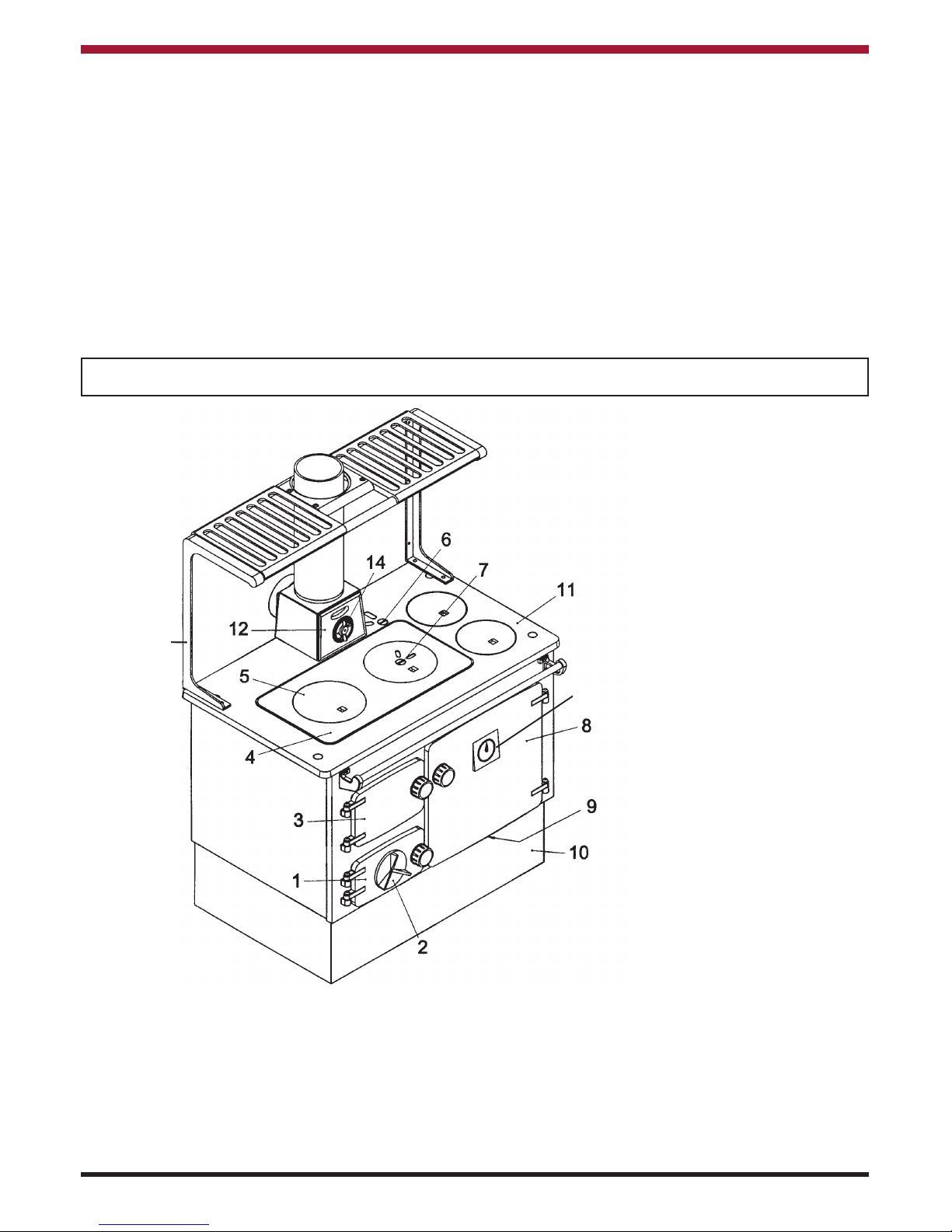
1. Ash Door
2. Spin Wheel
3. Fire Door
4. Hot Plate
5. Fuelling Cup
6. Chimney Damper
7. Oven Damper
8. Oven Door
9. Cleaning Door
10. Front Plinth
11. Hob
12. Bonnet
13. Plate Rack (optional)
14. Spin Valve
15. Oven Thermometer
Cooker Outputs: At 2.7 kg = 6 lbs coal / hr = 12,300 Btu’s / lb = 7.9 kW / kg
At 2.7 kg = 6 lb timber or peat = 8,600 Btu’s = 5.54 kW / kg
Heat to Water Domestic 10,000 Btu’s = 2.9 kW
Heat to Water 15K Central Heating 15,000 Btu’s = 4.4 kW Burning Coal
Heat to Water 21K Central Heating 21,000 Btu’s = 6.2 kW Burning Coal
Cooker Weight 163Kgs
IMPORTANT NOTICE: Any alteration to this appliance that is not approved in writing by Waterford Stanley will
render the guarantee void.
TECHNICAL DATA
All technical data are taken under laboratory conditions and may vary in use.
Fig.1
13
15
Page 4
SPECIFICATION
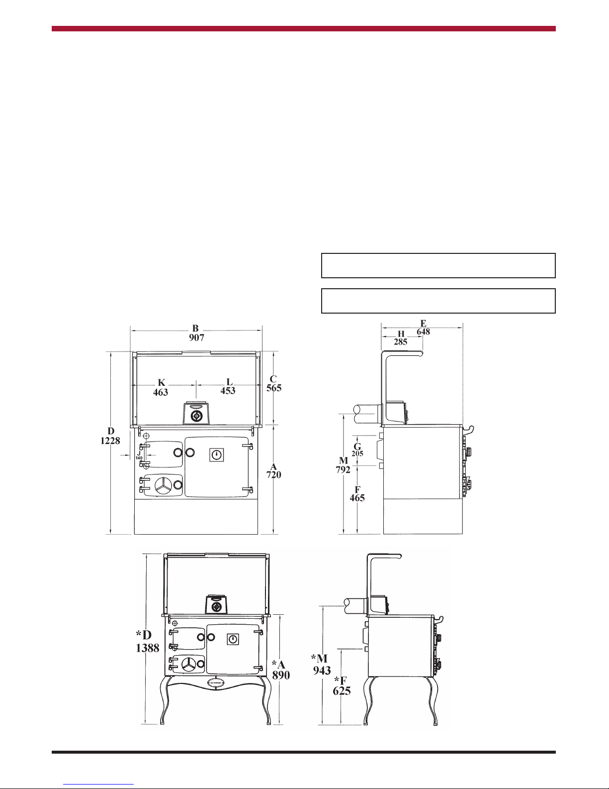
BOILER TAPPINGS:
10K Domestic Boiler:
F = 450 (17
3
/4”) G = 210 (81/4”)
15K Central Heating Boiler:
G = 205 (8”) F = 465 (18
1
/4”)
21K Central Heating Boiler:
F = 475 (18
3/
4”) G = 200 (8”)
IMPORTANT - Control of Substances Harmful to Health:
It is the Users/Installers responsibility to ensure that the necessary personal protective clothing is worn when
handling materials that could be interpreted as being injurious to health a and safety.
When handling Firebricks, Fire Cement or Fuels, use disposable gloves. Exercise caution and use disposable
masks and gloves when handling glues and sealants. When working with fibre glass, mineral wool, insulation
materials, ceramic blanket/board or kerosene fuel oil, avoid inhalation as it may be harmful. Avoid contact with
skin, eyes, nose and throat. Use disposable protection. Installation should be carried out in a well ventilated
area.
Manufacturers reserve the right to make alterations to design, materials and construction for manufacturing or other reasons subsequent to publication.
* Note:Optional legs are available for this cooker.
See Fig.3.
Note: Dimensions stated are in millimetres and
may be subject to a slight +/- variation.
3
Fig.2
Fig.3
Page 5

4
INSTALLATION INSTRUCTIONS FOR PLUMBER.
The installation must comply with the following:
The Building Regulations: Part J England & Wales,
Part F Section III Scotland, Part L Northern Ireland.
The Building Regulations: Part J Ireland
Health & Safety at Work Act.
B.S. 8303: Part 1, 2 & 3 - Installation of domestic
heating & cooking appliances using solid mineral
fuels.
B.S. 7593: Treatment of Water in Domestic Hot
Water Systems.
B.S. 7074: Part 1 & 2 - Hot water supply.
I.S. 258: Part 1 & 2 - Domestic Solid Fuel Cookers
with integral boilers.
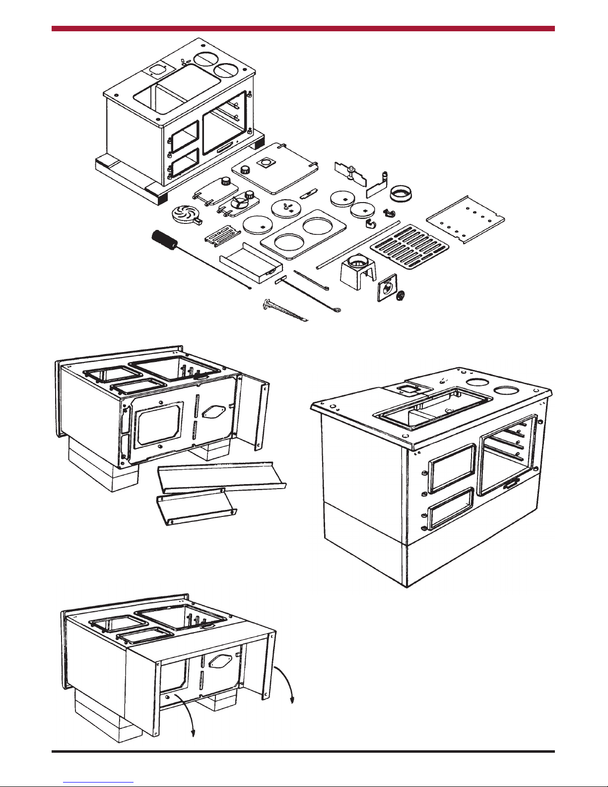
SITE ASSEMBLY INSTRUCTIONS
1. Remove carton by breaking banding straps.
2. Remove all loose items from Cooker.
3. Carefully lay Cooker on its back.
4. Unwrap Base Assembly Sheet Metal (3
pieces).
5. Bolt Angle End Plates to Cast Iron Cooker
Base using 4 x 5/16” screws provided in
envelope.
6. Fit Front Panel and fix with 4 Self-Tap
Screws, also provided in envelope.
7. Position Assembled Base Unit centrally on
Cooker and tighten all attachment screws.
The hot water available with normal usage of the
range is sufficient for normal domestic
requirements, provided the following conditions of
installation are fulfiled:
(a)The capacity of the storage cylinder does not
exceed 30 gallons.
(b)The cylinder is lagged and is fixed upright.
(c) The cylinder is connected by 1” (25mm) flow and
return pipes with a continual rise and not more
than 8.8 mts. (30 ft.) each in total length. Also if
they exceed 4.5 mts. (15ft.) each in total length
they must be lagged.
(d)Draw off pipes must be ‘dead-leg’ connections,
i.e. there must be no circuit in the draw off: the
user should be advised that the fire should be
continuous burning.
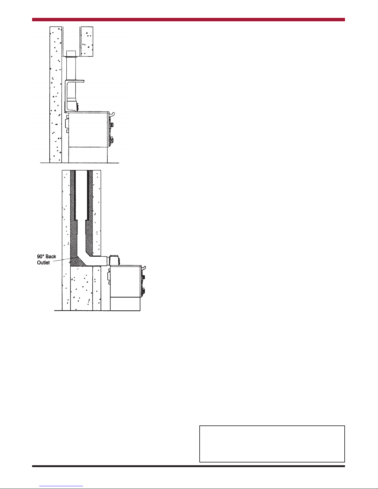
The Flue Connection
Two methods of installation are illustrated in the
diagrams. All joints must be sealed. Square bends
and horizontal runs must not be used. Means of
sweeping the chimney must be provided.
The Boiler
Flow and return connections can be made to run
either L.H. or R.H. from the back of the boiler.
Make good any breakage in the firebox cement
joints between the firebricks and the boiler.
The Hotplate
See that this is firmly bedded to the hob by the
fireproof rope provided.
Lighting Test
Check the installation before leaving the site. Allow
the Range to heat up slowly at first. Check that the
flow pipe from the boiler is assembled in the correct
way. Check the dampers and catches. See that
the user has a copy of the working instructions.
Note: Where a Stanley Range is installed in a
recess which is closed off by a register plate, the
flue pipe should be carried up into the throat of the
chimney to ensure satisfactory results. All flue
joints must be airtight - air should enter the chimney
only by passing through the firebox, or spin valve
item No.3 in the exploded view.
Page 6
5
1. Lay cooker on it’s back on an old blanket.
2. Attach end plates and front with screws
provided.
3. Stand cooker on it’s base.
4. Move cooker into it’s location and replace all
parts removed.
Parts removal before attaching the base.
Fig.4
Fig.5
Fig.6
Fig.7
Page 7
6
INSTALLATION
Fig.8
Fig.8a
LOCATION
When choosing a location for this appliance you
must have:
(a) Sufficient room for the installation (see
clearances), a satisfactory flue, and an
adequate air supply for correct
combustion and operation.
(b) Adequate space for maintenance and
air circulation.
(c) Solid floor or base of non-combustible
material which is capable of supporting
the total weight.
PRE-INSTALLATION CHECK
Before installing your new Cooker, check that the
chimney is clean and clear of obstructions.
Cracked brickwork and leaking joints should be
made good and tested accordingly. The chimney
should have a cross sectional area of at least 176
sq. cm (28.28 ins) or an inner diameter of 15 to
23cm (6 to 9 ins). A similar direct air inlet is
required in the room to support combustion.
CHIMNEY/FLUES
The chimney should have a cross sectional area of
at least 176 sq. cm (28 sq. ins) or an inner diameter
of 150mm to 230mm. (6” to 10”). (See fig. 8 & 8a).
Do not connect to a chimney serving another
appliance. Always ensure that the connection is to
a chimney of the same size, never connect to one
of smaller dimensions. Chimneys wholly
constructed of single skin are not recommended
under any circumstances. Due to their inability to
retain heat, such chimneys will inevitably give rise
to smoking, down draught and the formation of
condensation.
The flue must be high enough (more than 4.6m
(15ft.) in any case) to allow the flue gasses to vent
into clear air, away from the turbulence that may be
caused by roof structures, other chimney stacks
etc. The venting position should be 1.0m (3’3”)
above any obstruction within a 7.6m (24’9”) radius,
if down draughts are to be avoided.
COOKER CLEARANCE
The Cooker should not be installed at zero
clearance to combustible materials. The sides
should have a minimum clearance of at least 7.5
cm (3”) from combustible materials unless
otherwise fully insulated.
FLUE PIPES
Where the standard masonry chimney is not
available, a proprietary type of non-combustible or
non-corrosive material 125mm (5”) twin wall, fully
insulated pipe may be used. The pipe must
terminate at a point not lower than the main ridge or
adjacent outside obstructions. With such
installations access to the chimney must be
provided for cleaning purposes.
Horizontal runs more than 150mm (6”) and 90
o
bends numbering more than 2 per installation
should be avoided.
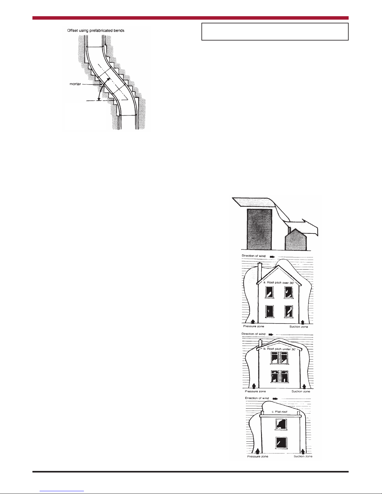
Flues should be vertical wherever possible and
where a bend is necessary, it should not make an
angle of more than 37.5owith the vertical.
IMPORTANT: ALL FLUE CONNECTIONS MUST
BE THOROUGHLY SEALED: BLOCKED
CHIMNEY’S ARE DANGEROUS, USE ONLY
RECOMMENDED FUELS, KEEP CHIMNEYS
AND FLUEWAYS CLEAR.
Page 8
NOTE: Where the appliance spigot or flue pipes
protrudes into the chimney, care should be taken to
ensure that it does not block the chimney.
DOWN DRAUGHTS
However well designed, constructed and
positioned, the satisfactory performance of the flue
can be adversely affected by down draught caused
by nearby hills, adjacent tall buildings or trees.
These can deflect wind to blow directly down the
flue or create a zone of high pressure over the
terminal.
A suitable anti-down draught terminal or cowl will
usually effectively combat direct down blow but no
cowl is likely to prevent down blow due to a high
pressure zone. Ensure that any cowl used will not
restrict the flue exit.
CHIMNEY CLEANING
Whichever type of flue is chosen, there must be
cleaning access to the whole of the flue system.
The flue of the chimney will need to be cleaned
regularly. How often will depend a lot on how your
Cooker is run, but, to start with, make a point of
inspecting the flue system every one or two weeks.
This period may well be extended as time goes by
if there is little sign of deposits. Some people find
they need to sweep the flue every six to eight
weeks.
HEARTH CONSTRUCTION
Hearth should be strong enough to support total
weight of cooker. When a properly constructed
hearth is not available we recommend that the
Cooker be placed on a slab of foamed concrete 7.5
cm (3”) or a slab of other insulating material. This
hearth must extend at least 40 cm (16”) to the front
and 30 cm (12”) to each side.
A flue pipe should only be used to connect an
appliance to a chimney and should not pass
through any roof space.
Flue pipes may be of any of the following materials:
(a) Cast iron as described in BS 41:1973
(1981)
(b) Mild steel with a wall thickness of at least
3mm.
(c) Stainless steel with a wall thickness of at
least 1mm and as described in BS EN
10095:1999 specification for stainless and
heat resisting plate sheet and strip, for
grade 316, S11, 316 S13, 316 S16, 316
S31, 316 S33, or equivalent Euronorm
88-77 designation.
(d) Vitreous enamelled steel complying with BS
6999: 1989.
STANLEY CAST IRON PIPES ARE HIGHLY
RECOMMENDED FOR INTERIOR USE.
7
Fig.10
Fig.9
A bend should not
make an angle of
more than 37.5
o
with the vertical.
Page 9

USE OF EXISTING FLUES OR CHIMNEY’S
An existing flue pipe or chimney that has proven to
be satisfactory when used with another solid fuel
appliance can normally be used for this appliance
provided that its construction, condition and
dimensions are acceptable. Flues that have proved
to be unsatisfactory, particularly with regard to
down draught, should not be considered for venting
this appliance until they have been examined and
any faults corrected. If there is any doubt about an
existing chimney a smoke test should be carried
out.
Before connecting this appliance to a chimney or
flue pipe which has previously been used with
another flue, the chimney or flue pipe should be
thoroughly swept.
When a chimney is not to be lined a suitable void
should be provided at the base to contain any
debris which may fall from the inside wall, so as to
prevent the debris from obstructing the appliance
flue outlet. (Removal of debris should be facilitated
by the provision of an access door).
VENTILATION & COMBUSTION AIR
REQUIREMENTS
It is imperative that there is sufficient air supply to
the cooker in order to support correct combustion.
The air supply to this appliance must comply with
B.S. 8303: Part 1.
A permanent air entry or opening with a total free
area of at least 550mm
2
per kW of rated output
above 5kW shall be provided but in no case less
than 6500mm2. Where a flue draught stabiliser is
used the total free area should be increased by
300mm2for each kW of rated output as per Building
Regulations Part J.
If there is another appliance using air fitted in the
same or adjacent room, it will be necessary to
calculate additional air supply.
All materials used in the manufacture of air vents
should be such that the vent is dimensionally stable
and corrosion resistant.
The effective free area of any vent should be
ascertained before installation. The effect of any
screen should be allowed for when determining the
effective free area of any vent.
Air vents direct to the outside of the building should
be located so that any air current produced will not
pass through normally occupied areas of the room.
An air vent outside the building should not be
located less than the dimensions specified within
the Building Regulations from any part of any flue
terminal. These air vents must also be fire proofed
as per Building Regulations.
Air vents in internal walls should not communicate
with bedsits, toilets, bathrooms or rooms containing
a shower.
Air vents traversing cavity walls should include a
continuous duct across the cavity. The duct should
be installed in such a manner as not to impair the
weather resistance of the cavity.
Joints between air vents and outside walls should
be sealed to prevent the ingress of moisture.
Existing air vents should be of the correct size and
unobstructed for the appliance in use.
If there is an air extraction fan fitted in the room or
adjacent rooms where this appliance is fitted,
additional air vents will be required to eleviate the
possibility of spillage of products of combustion
from the appliance/flue while the fan is in operation.
Where such a installation exists, a test for spillage
should be made with the fan or fans and other
appliances using air in operation at full rate, (i.e.
extraction fans, tumble dryers) with all external
doors and windows closed.
If spillage occurs following the above operation, an
additional air vent of sufficient size to prevent this
occurrence should be installed.
TOP & REAR OUTLET
Fig.11
Flue collar to be
connected to top or rear
exit of bonnet ONLY.
Seal joint between back
outlet spigot (item 4)
and bonnet (item 1) with
fire cement.
8
Page 10

9
PLUMBING
Diagrams illustrate the basic principles of water systems and are not to be regarded as working drawings.
Central Heating and Indirect Domestic Hot Water.
Recommended indirect cylinder 135 litres, depending on domestic requirements with a 28mm flow and return
pipes not exceeding 7.8m each in length. Cylinder and pipework should be lagged to minimise heat losses.
NOTE: We strongly advise the use
of pipe lagging and also the use of
a frost thermostat if the installation
is likely to be exposed to situations
where the temperatures will drop to
a level consistent with frost.
Fig.12
MOURNE
STANLEY
COOKER
HEATING SYSTEM
The system must include a gravity circuit with
expansion pipe, open to the atmosphere. The
central heating will normally be pump-driven as with
other types of boilers. The primary air valve
controls the heating rate of the boiler, Closed =
minimum, Open = maximum output.
See operating instructions.
BOILER OUTPUT (Central Heating)
High output cannot be maintained unless fuel is
being burned at a rate of 2.7 kg. per hour of coal.
When burning wood or peat, reduced outputs will
apply because of the lower calorific value of the
fuels.
GRAVITY CIRCUIT
The gravity circuit consists of a domestic hot water
tank of 135 litres Indirect Cylinder for central
Heating units and Direct Cylinder for Domestic Hot
Water Unit fixed in an upright position,
recommended for hot water storage and it should
be connected to the boiler by 28mm diameter flow
and return piping. The pipes should not exceed
7.8m each in length and anything in excess of 4.6m
must be fully lagged. The shorter the run of pipe
work the more effective the water heating efficiency
and to this end, the cylinder should be fully lagged.
In the interest of safety do not have any valves on
this circuit.
Page 11

HEATING
Care should be taken to ensure that the heating
installation is correctly installed and that it complies
with all relevant codes of practice. If this appliance
is being connected to an existing system, it is
strongly recommended to check the following.
(a) That the pipework is adequately insulated
(where applicable).
(b) Check all controls e.g. pump, radiator
valves etc, are operating satisfactorily and
are compatible with the requirements of the
cooker.
(c) Cleanse the system and add suitable
inhibitor.
Only competent personnel should be employed to
carry out your heating installation.
PIPE FITTINGS
Materials used for installation work should be fire
resistant, sound and should conform to the current
editions of the following or their equivalent:
1. Ferrous Materials
B.S. 1387: Steel Tubes
B.S. 4127: Stainless Steel Tubes
B.S. 1740: Steel Pipe Fittings
B. S. 6956: Jointing Materials
2. Non-Ferrous Materials
EN 29453: Soft Solder Alloys
B.S. 864: Compression Tube Fittings
B.S. 2871 & EN 1057: Copper & Copper
Alloys.
FUELS
The Cooker output levels are assessed on standard
House Coal of good quality. Reduced outputs will
result when fuels of low calorific values are used.
Wood logs up to 21cm long are suitable.
All fuel should be stored under cover and kept as
dry as possible prior to use.
WATER CIRCUIT TEMPERATURE
The return water temperature must be maintained
at not less than 50º C so as to avoid condensation
on the boiler and return piping. Fitting a pipe
thermostat to the return from the gravity circuit and
wiring it into the pump control will ensure than no
cold water will be returned from the central heating
circuit before the water from the gravity circuit has
warmed up the common return pipe and boiler. If
this is not sufficient to keep the boiler temperatures
above the required minimum, a three-way mixing
valve may be fitted to the flow pipe to divert some
CARE FOR YOUR CENTRAL HEATING
SYSTEM
We strongly recommend the use of suitable
corrosion inhibitors and anti-freeze solution in your
heating system, in an effort to minimise black oxide,
sludge and scale build-up, which effects efficiency.
In hard water areas the use of a suitable limescale
preventer / remover is advised.
Use only quantities specified by the water treatment
product manufacturer. Only add to the heating
system after flushing and finally refilling. Refer to
BS 7953.
INJECTOR TEE (Central Heating)
10
Fig.13
Fig.14
hot water straight back into the return. Such a
valve can be operated either manually or
electrically in conjunction with a return pipe
thermostat.
Page 12

EXPLODED VIEW
11
1. Bonnet
2. Bonnet Door
3. Spin Valve
4. Back Outlet Spigot
5. Top Flue Spigot
6. Hot Plate Cup (LH)
7. Hot Plate Cup (RH)
8. Hot Plate
9. Cleaning Cups
10. Hot Plate Cord
11. Hob
12. Sheet Iron Back (LH)
13. Back Sealing Plate
14. Sheet Iron Back (RH)
15. Oven Back Insulation
16. Flue Back
17. Boiler Back Insulation
18. Oven Back
19. Hob Protection Plate (Large)
20. Hob Protection Plate (Small)
21. Sheet Iron Side
22. Side Insulation
23. Oven End Flue Top
24. Back Flue Guide
25. Damper Guide (RH)
26. Direct Damper
27. Damper Guide (LH)
28. Oven End Flue Bottom
29. Oven Side (RH)
30. Front Flue Guide
31. Steam Escape
32. Oven Damper
33. Oven Top
34. Oven Shelf Cast Iron
35. Oven Shelf Sheet Iron
36. Oven Bottom
37. Mild Steel Glass Lined Boiler
38. Plastic Boiler Plugs
39. Oven Side Brick M3-980
40. Oven Side (LH)
41. Boiler Zest
42. Fire Box LHS Top Brick
43. Fire Box LHS Bottom Brick
44. Sham Cheek
45. Fire Box Front Top Brick
46. Grate
47. Fire Box Base Insert
48. Fire Box Base
49. Ash Tray
50. Ashpit Back
51. Ashpit Side (LH)
52. Ashpit Bottom
53. Ashpit Side (RH)
54. Fall Bar Frame Back
55. Stay Rods
56. Fall Bar
57. Fall Bar Frame Front
58. Fire Box Front Bottom Brick
59. Serial Number Plate
60. Front
61. Towel Rail Bracket (RH)
62. Towel Rail
63. Oven Door Panel Sheet Iron
64. Fire Door Lining
65. Fire Door Insulation
66. Fire Door Rope
67. Fire Door Insulation Panel
68. Oven Door Rope
69. Oven Door Insulation
70. Fire Door
71. Ashpit Door Rope
72. Ashpit Door
73. Ashpit Spin Valve
74. Oven Door
75. Thermometer
76. Door Handles (3)
77. Cleaning Door Clip
78. Cleaning Door
79. Towel Rail Bracket (LH)
80. Base
81. Flue Check
82. Front Plinth (Sheet Iron)
83. Side Legs (2) Sheet Iron
84. Poker
85. Scraper
86. Cast Iron Cup Lifter
87. Non Boiler Back Top
88. Non Boiler Back Bottom
89. Non Boiler Brick
90. 15K Central Heating Boiler
91. 21K Central Heating Boiler
92. Pipe }
93. Bend } - Special Order
94. Cleaning Brush
95. Optional Legs
Page 13

12
MOURNE EXPLODED VIEW
Page 14

13
Where the gravity and central heating circuits join
together to return to the Cooker we recommend the
use of an injector tee connection, situated as close
to the unit as possible. This type of tee encourages
a stable flow of hot water through both circuits and
helps to prevent priority being given to the stronger
flow, which is most commonly the pumped central
heating circuit. This way, there will be no shortage
of hot water to the taps when the heating is on.
DRAINING
Key - operated drain taps to B.S. 2879 should be
provided in accessible positions in all low parts of
the system. However it should be noted that there
may be short sections of pipework e.g. when
passing under doorways that may be possible to
drain.
GENERAL MAINTENANCE
It is important that the user is familiar with their
heating system and that they ensure regular checks
and maintenance which can limit unnecessary
break-downs.
We recommend that you evaluate the overall
insulation in your house, i.e. attic, external walls,
windows, external doors. Insulation and draught
proofing can greatly reduce running costs, while
equally enhancing living conditions.
DRAUGHT REQUIREMENTS
Remember, a proper flue is necessary for the
efficient operation of your solid fuel cooker to
provide a steady draught of:
0.06 INS. TO 0.10 INS. W.G.
1.52 MM TO 2.54 W.G.
Page 15

IMPORTANT NOTES
Now that your Stanley solid fuel cooker is installed and no doubt you are looking forward to many comforts it
will provide, we would like to give you some tips on how to get the best results from your cooker.
1. We would like if you could take some time to read the operating instructions/hints, which we are
confident, will be of great benefit to you.
2. Do not burn fuel with a high moisture content, such as a damp peat or unseasoned timber. This
will only result in a build up of tar in the cooker and in the chimney.
3. Clean the flue-ways of the cooker every week and ensure that there are no blockages. Please
refer to manual for instructions.
4. Before loading fresh fuel into the firebox, riddle fully to remove all ashes this will allow better and
cleaner burning. See directions in manual.
5. Never allow a build up of ashes in the ash pan, as this will cause the grate to burn out prematurely.
6. Avoid slow burning of damp or unseasoned fuel as this will result in tarring flue ways and chimney i.e. peat or timber.
7. Allow adequate air ventilation to ensure plenty of air for combustion.
8. Do not burn rubbish/household plastic.
9. Do not leave ash-door open for long periods as this will over heat the unit causing unnecessary
damage.
10. Clean the chimney at least twice a year.
11. When burning peat or timber, it will be helpful to burn a few fires of “Anthracite” which will help
to dry and burn off tar and soot deposits. This will be helpful before cleaning.
12. Burning soft fuels such as timber and peat will stain the glass. Regular cleaning will prevent permanent staining.
13. Keep all combustible materials a safe distance away from unit, please consult manual for clearance to combustible table.
14. For safety reasons never leave children unaccompained while stove/cooker is in use.
15. Avoid contact with unit when in use as cooker/stove reaches very high operating temperatures.
FUEL CALORIFIC VALUES - SOLID FUELS
Anthracite 25-50mm C.V.: 8.2kW/Kg 14,000 BTUs/lb
House Coal 25-75mm C.V.: 7.2kW/Kg 12,000 BTUs/lb
Timber - Firebox size C.V.: 5.0kW/Kg 8,600 BTUs/lb
Peat Briquettes C.V.: 4.8kW/Kg 8,300 BTUs/lb
Bog Peat C.V.: 3.4kW/Kg 6,000 BTUs/lb
14
Page 16

LIGHTING THE FIRE
1. Open the Fire Door and lower the Fire Fence or open the top fuelling
cup.
2. Fully open all dampers and the Primary Air Inlet Spin Valve.
3. Kindle with paper and sticks in the usual way.
4. Ignite by using a taper or rolled wad of paper inserted into the ashpan.
5. Under no circumstances should any flammable liquid i.e. petrol,
paraffin etc. be used to light the fire.
6. When the fire is well established close the Direct Flue Damper fully and
keep it closed.
7. Add fuel to the firebox as required.
8. Adjust primary air opening to suit the current requirements.
Note: Do not operate with ashpit door open.
15
Page 17

16
OPERATING THE COOKER
Fig.15
FUELLING
Using the recommended fuels, access is through
the fire door or the fuelling cup. To fuel, lift and tilt
the Fire Fence outwards. Note: When burning
timber logs the fire fence may be removed to
simplify front loading, make sure that the logs are
no longer than the recommended size so that the
fire door can be fully closed.
When refuelling open the fire damper. After
refuelling be sure to close the damper otherwise
oven temperature will drop and the fire box may
overheat.
CONTROL
The air supply to the fire is controlled by the spin
valve situated on the ash door. Depending on the
setting a high or low firing condition will be
determined by the volume of air passing through at
any one time.
DIRECT FLUE DAMPER
The direct damper as already advised must be kept
closed at all times except when kindling a new fire
or refuelling.
A secondary flue damper position can be used
which allows the damper to be partly opened to
give better burning in marginal draught conditions.
OVEN DAMPER
When using oven, operate damper in open position.
OVER-FIRING
When using anthracite, coke or coal avoid
excessive firing conditions. High temperatures are
unnecessary and can only do serious harm to the
cooker. The first indication that overheating is
taking place will be the formation of Clinker (Melted
Ash) in the firebox and this should be removed
immediately otherwise damage will occur not only
to the cooker components but also to the fire bricks
and any damage here should be repaired without
delay.
THE HOTPLATE
For best results use heavy based, flat bottomed
utensils. When cleaning your cooker ensure that
the underside of the hot plate is also attended to as
hard carbon and soot can build up here to such a
degree that the surface of the hotplate is being
insulated from the fire and this will, of course,
drastically reduce efficiency.
MAIN OVEN
When baking or roasting, open the oven damper
and Spin Valve fully until the thermometer shows a
temperature about 50oF (10ºC) higher than that
which is required. Then close the Spin Valve to a
point where the required temperature is sustained
(a little practice will soon show how much
adjustment is necessary). Much will also depend
on the strength of the chimney draught. Remember
the direct flue damper must be kept fully closed as
a by-pass is provided to allow waste gases through
at all times. When baking or roasting, if it is found
that the surface of the food is cooking too quickly
then position the plain steel shelf in the top of the
oven so as to act as a heat shield which will protect
the food on the shelf beneath.
Fig.16
Page 18

Fig.17
Spin Valve
17
EMPTYING THE ASHPAN
The ashpan must be emptied regularly otherwise
ash will build up to a point where it interferes with
the natural flow of cool air through the fire bars and
as a consequence these will be damaged.
COOKER FLUE CLEANING
Your Stanley Cooker should be cleaned out at least
once a week although this may be extended to two
weeks if smokeless fuel is used. e.g. anthracite,
phurnacite or similar manufactured fuels.
This procedure is as follows: Remove all loose
sections on top of the Cooker. Open the direct
damper. Where a flue chamber is fitted in
conjunction with a vertical flue pipe remove the
cleaning door from the front of this fitting in order to
obtain access.
All deposits from the flue pipe and the top of the
oven may be brushed both into the firebox and
down the right hand side of the oven. Deposit
which has accumulated on the side of the oven
must also be brushed downward and particular
attention must be paid to the back flueway
which runs from the top flue outlet down to the
bottom left corner immediately underneath the
oven. To remove the accumulated ash and soot
take off the cleaning plate situated immediately
under the oven on the front of the Cooker and
thoroughly clean out the residue from the side flue,
back flue and base plate - this operation is
essential otherwise the flow of hot gases will be
obstructed and satisfactory oven temperatures
will not be maintained, apart from which such
deposits may contribute to smoking. Replace all
the loose parts which have been removed making
sure that all cooking surfaces have been thoroughly
cleaned on the underside.
OVERNIGHT BURNING
Open the spin valve by a quarter turn and close the
oven damper; riddle the fire and refuel. In the
morning open the air valve and damper and riddle
the fire; when it is again burning brightly, refuel. If
it is found that the fire is completely burned out then
new settings should be tried in respect of the spin
valve. On the other hand if the fire is out and the
fuel unburned then the reverse should apply.
BOILER SUMMER CONDITIONS (Central
Heating)
To obtain a reduction in boiler output during the
summer the central heating model is supplied with
a set of cast iron heat shield plates as standard
equipment. Two of them are positioned on the
hooks welded to the face of the boiler and boiler
back and are easily positioned and removed.
Maximum heat reduction is achieved by using all
the plates provided. If, however, increased output
is desired then plates can be removed
progressively to the point where the required output
is obtained.
These heat shield plates have no function other
than to reduce the boiler output.
DOMESTIC BOILER UNIT
A normal fire will provide sufficient hot water to
meet your needs. Increase the burning rate to heat
oven up to the required temperature.
RIDDLING
Open the ashpit door and direct damper to their
fullest extent. Fit the riddling tool on to the spigot
provided at the front of the fire bar and move the
bar vigorously to and fro. It is recommended that
the fire bed itself be thoroughly raked at regular
intervals thus loosening up such debris as Clinker,
Stones, etc., which are then easily removed.
Page 19

Remove all loose fitting parts, hotplate, bonnet door
from the top of the cooker. Open the direct damper.
Where a flue chamber is fitted in conjunction with a
vertical flue pipe remove the cleaning door from the
front of this fitting in order to obtain access. See
Fig.18.
To remove all the accumulated deposits take off the
cleaning plate situated immediately under the oven
on the front of the cooker and thoroughly clean out
the residue from the side flue, back flue and base
plate. This operation is essential otherwise the flow
of combustion gases will be obstructed or even
stopped, and satisfactory oven temperature will not
be maintained, apart from which such deposits will
cause smoking. See Fig.22.
Replace all loose parts which have been removed
making sure that all cooking surfaces have been
thoroughly cleaned on the underside. See Fig.23.
18
CLEANING INSTRUCTIONS
Fig.18
Fig.19
Fig.20
Fig.21
Fig.22
Fig.23
All deposits from the flue pipe and the top of the
oven may be brushed both into the firebox and
down the back flue passage way. See Fig. 19 & 20.
Deposits which have accumulated on the side of
the oven must also be brushed downward and
particular attention must be paid to the back
flueway which runs from the bonnet down to the
bottom left corner immediately underneath the
oven. See Fig.21.
Flue Way Cleaning Brush
Flue Way Cleaning
Brush
Flue Way Cleaning
Brush
Page 20

CLEANING
IMPORTANT: BE CAREFUL OF THE HOT
APPLIANCE.
General cleaning must be carried out when the
cooker is cool.
This cooker is finished in a high gloss vitreous
enamel. To keep the enamel in the best condition
observe the following tips:
1. Wipe over daily with a soapy damp cloth,
followed by a polish with a clean dry duster.
2. If milk, fruit juice or anything containing acid is
spilt on the top plate or down the cooker, be
sure to wipe it immediately or the vitreous
enamel may be permanently discoloured. Jam
and preservatives containing sugar can
permanently damage the vitreous enamel.
3. Keep a damp cloth to hand while cooking, to
wipe up any spills as they occur, so they do not
harden and become more difficult to remove
later.
4. If spills do become baked on a cream cleanser
can be used. For stubborn deposits a soap
impregnated pad can be carefully used on the
vitreous enamel.
5. Use only products recommended by the
Vitreous Enamel Association, these products
carry the Vitramel label.
6. In the oven, spills and fat splashes are
carbonised at high temperatures: occasionally
brush out with a stiff brush. The shelves can be
soaked and cleaned with a cream cleanser.
7. Use a wire brush to keep the cast iron hotplate
clean.
DO NOT USE ABRASIVE PADS OR OVEN
CLEANERS CONTAINING CITRIC ACID ON
ENAMELLED SURFACES. ENSURE THAT
THE CLEANSER MANUFACTURERS
INSTRUCTIONS ARE ADHERED TO.
10K Domestic Boiler
21K Central Heating Boiler
19
Fig.24
Fig.25
Your new Stanley Cooker will give you every
possible satisfaction in use and many years of
service provided it is properly installed and
maintained in accordance with our published
instructions.
Page 21

20
15K Central Heating Boiler
Optional Plate Rack Installation
MILD STEEL
The steel side panels and splash back must not be
cleaned with steel wool. Use only washing up liquid
in hot water with a lint free cloth. dry off and apply
a coat of good quality furniture polish.
OVENS
Grease spillages will burn off from the oven interior,
when the oven is hot and any other loose materials
can be wiped out with a cloth, when cold. Stubborn
stains in the oven and on the shelves in the oven
can be cleaned off with a paste of bread soda and
water.
HOT PLATE
The hotplate may be cleaned using a small amount
of paraffin oil or fine steel wool to remove rust and
cooking stains. Dry off with a lint free cloth and
apply a light coat of cooking oil to preserve the
finish.
Fig.26
Fig.27
IMPORTANT
It is of the utmost importance to keep the flue pipe and chimney clear of deposits by regular sweeping
of the chimney irrespective of whether the fuel used is classed as smokeless or not. All fuels give rise
to soot or ash deposits and regular cleaning is essential for safe operation.
Blocked or partially obstructed flueways and chimneys will cause dangerous fumes to be emitted into
the room, these may well be invisible if a smokeless fuel is burned.
CO ALARM
Waterford Stanley recommend the fitting of a CO
Alarm in the same room as the appliance, this is a
requirement under UK Building Regulations.
Further guidance on the installation of a carbon
monoxide alarm is available in BS EN 50292:2002
and from the alarm manufacturers instructions.
Provision of an alarm must not be considered a
substitute for either installing the appliance
correctly or ensuring regular servicing and
maintenance of the appliance and chimney
system.
WARNING:-
If the CO Alarm sounds unexpectedly:-
1. Open Doors and windows to ventilate the
room and then leave the premises.
2. Let the fire go out.
Page 22

21
FAULT FINDINGS
1. Poor Chimney Draught (a) Obstruction (a) Clear and Clean
(b) Too Low (b) Raise Height above Ridge
(c) Too Wide (c) Fit Flue Liner 15 to 23 cm
(d) Crack in Wall (d) Repair Cracks
(e) Shared by another unit (e) Cut off other unit
2. Excessive Chimney Draught (a) High chimney (a) Adjust bonnet spin valve
3. Down Draught (a) High Trees (a) Raise Chimney Height
(b) High Buildings (b) Raise Chimney Height
(c) Low Chimney (c) Raise Chimney Height
(d) Negative Pressure Zone (d) Fit Cowl
4. Cooker Smoking (a) Insufficient Primary Air (a) Provide Room Air Inlet
(b) Chimney Choked (b) Clean Chimney
(c) Side and/or Back Flueways Choked (c) Clean Flueways
(d) Down Draught (d) Raise Chimney Height
5. Hot Plate Not Heating (a) Soot Under Hot Plate (a) Remove and Clean
(b) Fire Too Low (b) Build Better Fire
(c) Utensils not Flat (c) Use machined based Utensils
6. Oven Not Heating (a) Poor Chimney Draught (a) Raise Height or Fit Cowl
(b) Flue ways blocked with soot (b) Clean Out
(c) Damper open to Chimney (c) Close Damper
7. Radiators not Heating
(Central Heating)
(a) Pump not Working (a) Check and replace if defective
(b) Air in Radiators (b) Vent Radiators
(c) Pipe System Faulty (c) Check Pipe Sizes and Circuit
(d) Excessive Number of Radiators (d) Turn off un-needed Radiators
(e) Radiator Valves not Adjusted (e) Adjust Valves to Give even flow
8. Domestic Hot Water (a) Cylinder too Large (a) Lag Cylinder or use smaller cylinder
(b) Flow Pipe too small (b) Use 25mm Bore Pipe
(c) Flow Pipe crossed (c) Reverse Flow Pipe
(d) Cylinder too far away (d) Not more than 7.8m fully lagged
(e) Hot water from boiler not reaching
boiler
(e) Adjust Flow Control Valves or fit
injector-tee - Central Heating
9. Intermittent Performance (a) Cooker starved of Primary Air (a) Provide Air Inlet in Room
(b) Extraction Fan in room (b) Provide additional air inlet in room
(c) Cooker subjected to wind change (c) Raise Chimney or fit Cowl
(d) Dirty Flueways (d) Clean flueways frequently
(e) Poor Fire (e) Burn more fuel
(f) Uncontrolled Burning (f) Repair or replace Air Valve in Ash
door or replace sealing rope
10. Domestic Hot Water Rusty
(Central Heating Only)
(a) Leak in Indirect Cylinder Coil (a) Replace Cylinder
(b) Incorrect Cylinder Fitted (b) Check with installer
Page 23

COOKER INSTALLATION CHECK LIST
Flue System
1. Minimum Flue Height of 4.6 metres (15 feet).
2. Appliance should be connected to a minimum of 1.8 metres (6 feet) of 125mm (5”)
flue pipe with a horizontal run not exceeding 150mm (6”).
3. Appliance should be connected to a chimney of less than 250mm (8”) in diameter
(otherwise the chimney must be lined with a 6” flue liner).
4. The chimney venting position must be above the main ridge of the roof or adjacent
outside obstructions.
Location
5. Clearance to combustible materials must be maintained at 75mm (3”).
6. Clearance to non combustible materials must be maintained at 75mm (3”).
7. Clearance to combustible materials must be maintained as specified in the
Clearance to Combustibles section.
8. If the cooker is located on a combustible surface, a floor protector must be used to
cover the area underneath the heater, extending 18” from the front of the cooker
and 8” from the back & sides.
Plumbing
9. Appliance must be connected to a gravity circuit using 1” ID flow & return piping.
10. The length of pipes from the cylinder to the cooker should not exceed 7.8 metres
(25
1
/2 feet).
11. A circulation pump should be fitted to the return pipe and controlled by a pipe stat
fitted to the flow pipe of the gravity circuit to the cylinder.
Ventilation & Combustion Air Requirements
12. The room in which the appliance is located should have an air vent of adequate
size to support correct combustion (see Ventilation & Combustion Air Requirement
Section).
Tick
22
Page 24

Rev:010 DP130913
N00118AXX
24
Manufactured by
Waterford Stanley Ltd.,
Unit 401-403, IDA Industrial Estate, Cork Road,
Waterford, Ireland.
Tel: (051) 302300 Fax (051) 302315
www.waterfordstanley.com
www.stanleystoves.com
 Loading...