

Page 1
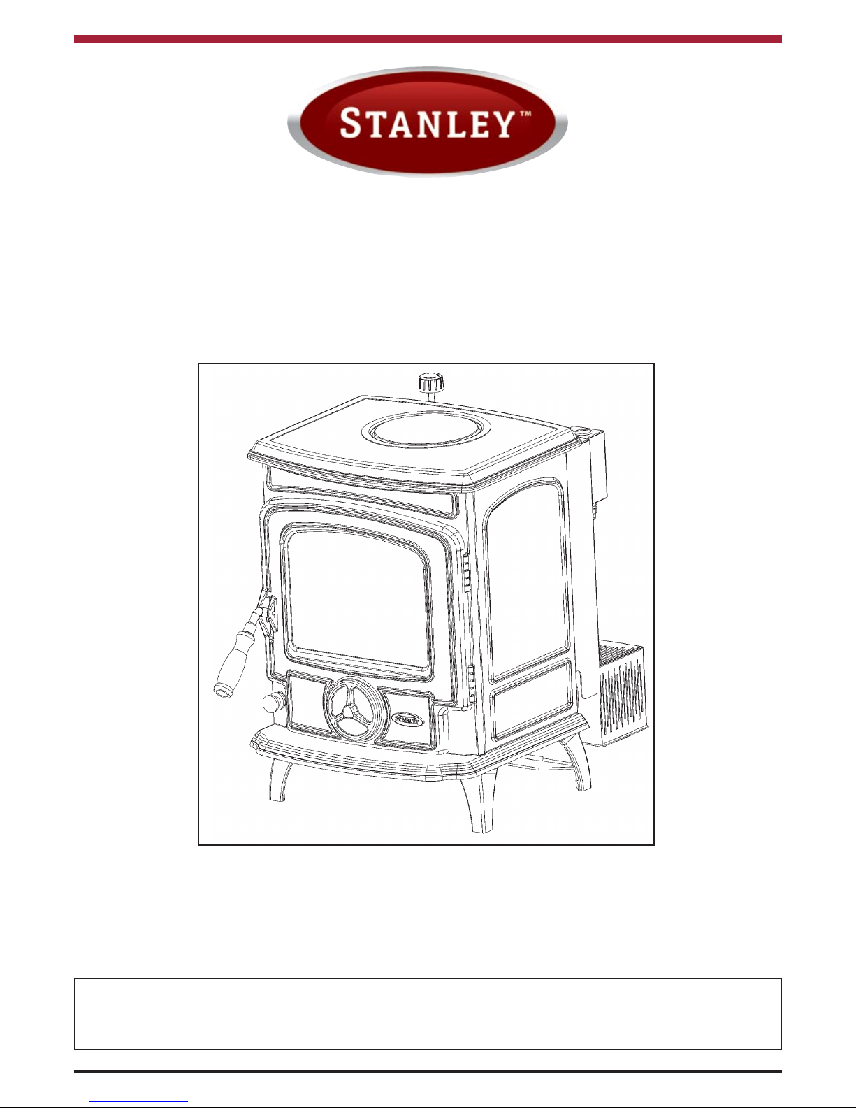
Oisin Oil Stove
MK III
INSTALLATION AND OPERATION INSTRUCTIONS
This appliance is hot while in operation and retains its heat for a long period of time after use. Children,
aged or infirm persons should be supervised at all times and should not be allowed to touch the hot
working surfaces while in use or until the appliance has thoroughly cooled.
Page 2

2
TABLE OF CONTENTS
Page No.
1. Stove Installation Instructions . . . . . . . . . . . . . . . . . . . . . . . . . . . . . . . . . . . . . . . . . . . . . 3
2. Introduction . . . . . . . . . . . . . . . . . . . . . . . . . . . . . . . . . . . . . . . . . . . . . . . . . . . . . . . . . . . 3
3. Commissioning Instructions . . . . . . . . . . . . . . . . . . . . . . . . . . . . . . . . . . . . . . . . . . . . . . 4
4. Stove Dimensions . . . . . . . . . . . . . . . . . . . . . . . . . . . . . . . . . . . . . . . . . . . . . . . . . . . . . . 4
5. Technical Data. . . . . . . . . . . . . . . . . . . . . . . . . . . . . . . . . . . . . . . . . . . . . . . . . . . . . . . . . 5
6. Installation . . . . . . . . . . . . . . . . . . . . . . . . . . . . . . . . . . . . . . . . . . . . . . . . . . . . . . . . . . . . 6
7. Location. . . . . . . . . . . . . . . . . . . . . . . . . . . . . . . . . . . . . . . . . . . . . . . . . . . . . . . . . . . . . . 6
8. Hearth Construction . . . . . . . . . . . . . . . . . . . . . . . . . . . . . . . . . . . . . . . . . . . . . . . . . . . . 6
9. Electrical Supply . . . . . . . . . . . . . . . . . . . . . . . . . . . . . . . . . . . . . . . . . . . . . . . . . . . . . . . 6
10. Flue Supply/Installation Oil Storage Tanks . . . . . . . . . . . . . . . . . . . . . . . . . . . . . . . . . . . 7
11. Flues . . . . . . . . . . . . . . . . . . . . . . . . . . . . . . . . . . . . . . . . . . . . . . . . . . . . . . . . . . . . . . . . 7
12. Fuel Line Supply . . . . . . . . . . . . . . . . . . . . . . . . . . . . . . . . . . . . . . . . . . . . . . . . . . . . . . . 7
13. Clearance to Combustible Material . . . . . . . . . . . . . . . . . . . . . . . . . . . . . . . . . . . . . . . . . 8
14. Clearance to Non Combustible Material . . . . . . . . . . . . . . . . . . . . . . . . . . . . . . . . . . . . . 8
15. Clearances to Non Combustibles . . . . . . . . . . . . . . . . . . . . . . . . . . . . . . . . . . . . . . . . . . 9
16. The Flue . . . . . . . . . . . . . . . . . . . . . . . . . . . . . . . . . . . . . . . . . . . . . . . . . . . . . . . . . . . . . 9
17. Top Flue / Rear Outlet . . . . . . . . . . . . . . . . . . . . . . . . . . . . . . . . . . . . . . . . . . . . . . . . . . . 9
18. Flueing . . . . . . . . . . . . . . . . . . . . . . . . . . . . . . . . . . . . . . . . . . . . . . . . . . . . . . . . . . . . . . 10
19. Flue Stabilizer. . . . . . . . . . . . . . . . . . . . . . . . . . . . . . . . . . . . . . . . . . . . . . . . . . . . . . . . . 11
20. Ventilation & Combustion Air Requirement . . . . . . . . . . . . . . . . . . . . . . . . . . . . . . . . . . 11
21. Installation Assembly . . . . . . . . . . . . . . . . . . . . . . . . . . . . . . . . . . . . . . . . . . . . . . . . . . . 12
22. Commissioning. . . . . . . . . . . . . . . . . . . . . . . . . . . . . . . . . . . . . . . . . . . . . . . . . . . . . . . . 12
23. Control Valve Rating . . . . . . . . . . . . . . . . . . . . . . . . . . . . . . . . . . . . . . . . . . . . . . . . . . . 13
24. Exploded View . . . . . . . . . . . . . . . . . . . . . . . . . . . . . . . . . . . . . . . . . . . . . . . . . . . . . . . . 14
25. Stove Operating Instructions . . . . . . . . . . . . . . . . . . . . . . . . . . . . . . . . . . . . . . . . . . . . . 15
26. Fuels . . . . . . . . . . . . . . . . . . . . . . . . . . . . . . . . . . . . . . . . . . . . . . . . . . . . . . . . . . . . . . . 15
27. Ventilation Requirements . . . . . . . . . . . . . . . . . . . . . . . . . . . . . . . . . . . . . . . . . . . . . . . . 15
28. Flue Draught . . . . . . . . . . . . . . . . . . . . . . . . . . . . . . . . . . . . . . . . . . . . . . . . . . . . . . . . . 15
29. Priming The Flue . . . . . . . . . . . . . . . . . . . . . . . . . . . . . . . . . . . . . . . . . . . . . . . . . . . . . . 15
30. Lighting The Stove . . . . . . . . . . . . . . . . . . . . . . . . . . . . . . . . . . . . . . . . . . . . . . . . . . . . . 16
31. Turning The Stove Off . . . . . . . . . . . . . . . . . . . . . . . . . . . . . . . . . . . . . . . . . . . . . . . . . . 16
32. Power Failure . . . . . . . . . . . . . . . . . . . . . . . . . . . . . . . . . . . . . . . . . . . . . . . . . . . . . . . . . 16
33. Servicing . . . . . . . . . . . . . . . . . . . . . . . . . . . . . . . . . . . . . . . . . . . . . . . . . . . . . . . . . . . . 16
34. User Servicing . . . . . . . . . . . . . . . . . . . . . . . . . . . . . . . . . . . . . . . . . . . . . . . . . . . . . . . . 17
35. Annual Servicing . . . . . . . . . . . . . . . . . . . . . . . . . . . . . . . . . . . . . . . . . . . . . . . . . . . . . . 17
36. Fire Safety . . . . . . . . . . . . . . . . . . . . . . . . . . . . . . . . . . . . . . . . . . . . . . . . . . . . . . . . . . . 17
37. CO Alarm . . . . . . . . . . . . . . . . . . . . . . . . . . . . . . . . . . . . . . . . . . . . . . . . . . . . . . . . . . . . 18
38. Vitreous Enamel Cleaning . . . . . . . . . . . . . . . . . . . . . . . . . . . . . . . . . . . . . . . . . . . . . . . 18
39. Fault Finding . . . . . . . . . . . . . . . . . . . . . . . . . . . . . . . . . . . . . . . . . . . . . . . . . . . . . . . . . 19
Page 3

INTRODUCTION
To ensure safety, satisfaction and reliable operation, this stove should be installed and commissioned by a trained
and competent person.
IMPORTANT NOTICE
As manufacturers of heating appliances we take every possible care to ensure, as reasonably practicable, that
these appliances are so designed and constructed as to meet the general safety requirements when properly
used, installed and maintained.
Control of substances harmful to health :
* It is the users/installers responsibility to ensure that the necessary personal protective clothing is
worn when handling materials that could be interpreted as being injurious to health and safety.
See below.
* When handling firebricks, fire cement or fuels use disposable gloves.
* Exercise caution, use disposable masks and gloves when handling glues and sealants. When working with
kerosene oil, fibre glass or mineral wool. Avoid contact with skin, eyes, nose and throat,
use disposable protection.
Installation should be carried out in a well ventilated area.
Any alterations to this appliance that are not approved in writing by Waterford Stanley will render the
guarantee void.
This appliance is hot while in operation and retains its heat for a long period of time after use. Children,
aged or infirm persons should be supervised at all times and should not be allowed to touch the hot
working surfaces while in use or until the appliance has thoroughly cooled.
The front door should only be opened if it is necessary to clean the glass. This should only be done
when the stove is cold.
This stove is designed for continuous or intermittent use -When stove is in continuous use it should be
serviced at least every 6 months. If it is not used for extended periods (i.e. during the summer months)
the service period can be extended to 9 - 12 months.
The complete installation must be done in accordance with current Standards and Local Codes. It
should be noted that the requirements and these publications may be superseded during the life of this
manual.
3
STOVE INSTALLATION INSTRUCTIONS
Page 4
COMMISSIONING INSTRUCTIONS
1. WHY SHOULD I HAVE MY STANLEY COMMISSIONED?
Your Stanley will need to be commissioned after installation to ensure that it is correctly and accurately
setup and that it operates economically and safely. The Stanley Approved Service Engineer will provide
a written report at the time of commissioning.
2. WHEN SHOULD I DO THIS?
The commissioning should be carried out as soon as possible after the installation is completed to
ensure the most economical use of your Stanley, failure to ensure prompt commissioning could affect
your warranty.
3. WHO SHOULD COMMISSION MY STANLEY?
Waterford Stanley has a nationwide coverage of Approved Service Engineers. These Engineers have
all attended a Stanley approved training course and are completely familiar with our products and will
ensure that it is functioning correctly and economically.
4. HOW DO I ARRANGE FOR MY COMMISSIONING?
Just simply phone the Waterford Stanley Call Centre on 00353 51-302300 and our staff will make
the arrangements for you. (Please have product serial number to hand).
COMMISSIONING IS CARRIED OUT FREE OF CHARGE.
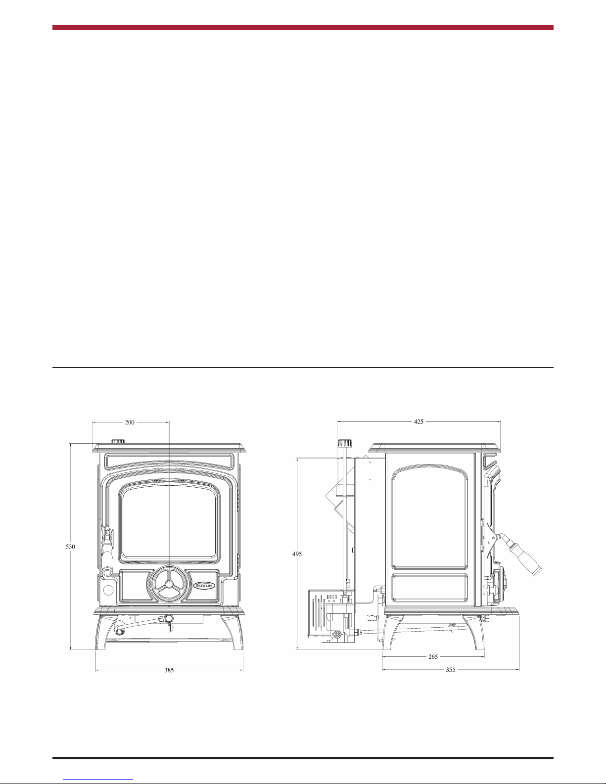
STOVE DIMENSIONS
4
Page 5
5
Note: Dimensions stated are in millimetres unless otherwise stated and may be subject to a slight +/- variation.
TECHNICAL DATA
Fuel: Kerosene 28 sec (Class C2)
Mains Current: 220V - 240V, 50Hz, A.C.
Supply Fuse Rating: 3 amp
Chimney Draught: 12 Pa
Flue Diameter: 5” (125 mm)
Note: To achieve the Maximum Output, the flue has to be capable of evacuating the products of combustion
generated at the maximum permitted oil flow rate.
All technical data are taken under laboratory conditions and may vary in use.
The manufacturers reserve the right to make alterations to design, materials or construction for manufacturing or other reasons subsequent to publication.
Max Flow Rate 10cc / min
Min Flow Rate 4cc / min
Max Permitted Flow Rate 10.5cc/min
Nominal Output
3.92kW
Output Range 1.5 - 3.92 kW
Weight 75kgs
Flue Gas Temperature (Nominal Output) 280oC
Flue Gas Mass Flow 17.5g/s
Appliance Class 5
b
Page 6
LOCATION
When choosing a location for this appliance you must
have the following:
A. Sufficient room for installation and servicing.
B. Adequate clearance to combustibles (see sec-
tion Clearance to Combustibles).
C. A satisfactory flue system (See Flue Systems).
D. Fixed fuel supply line and shut off valve
(See Fuel Supply).
E. Adequate air supply to support combustion (See
Ventilation & Combustion Air Requirements).
F. Proper fused power point (See Electrical
Supply).
G. Allow for adequate air circulation around stove.
H. Solid floor or base of non-combustible material
which is capable of supporting the total weight of
the stove. (See Hearth Construction).
I. Position in the area to be heated - central
locations are usually best.
J. Avoid installing the stove near door ways,
windows, walkways and areas with air
stream passing through.
NOTE: When passing through walls or ceilings
with the flue system:
K. Always check for obstructions for example
electrical fittings, wiring, ducting, plumbing
and fixed furnishings.
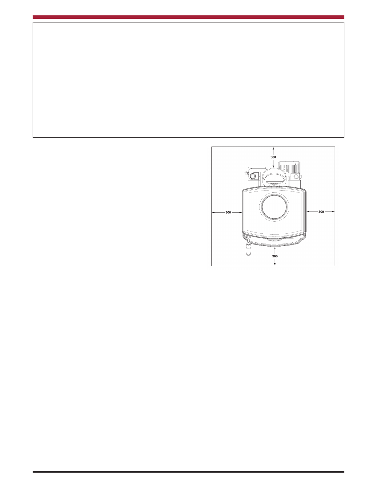
HEARTH CONSTRUCTION
When a non-combustible floor surface is not available
then the cooker must be placed on other insulating
material. We recommend a slab of precast concrete
40mm (1
1
/2
) inches deep. If other insulating material
is being used, the dimensions of the slab of this insulating material must afford similar protection. This
hearth must extend 300mm (12 inches) to either side
of the appliances and 300mm (12 inches) to the front.
Note: The hearth must be level, stable and capable
of supporting the stove.
ELECTRICAL SUPPLY
All wiring external to the appliance must conform to
the current B.S. 7671 (UK) B.S.7462 Safety Document 635: ETC Part 1 Section 5.4.6 & The Electricity
at Work Regulations.
The stove requires a 220 V - 240 V 50Hz supply.
Connection of the appliance and any system controls
to the mains supply must be through a moulded on
plug top which is fitted to the appliance in accordance
with EN 60335 and Consumer Protection S.I. 1994
No. 1768 Plug and Sockets (Safety) Regulations
1998.
NOTE: Always install in accordance with current local
wiring regulations.
WARNING: THIS SUPPLY MUST BE EARTHED
(Refer to B.S. 7430: Code of Practice for Earthing).
IMPORTANT: The appliance plug must be accessible and so, must not be obstructed and close to the
stove. To isolate the stove, completely unplug from
the mains socket. Persons in charge of this stove
should be aware of this socket outlet position.
6
Fig.1
INSTALLATION
The installation must be completed in accordance with current National and European Standards and Local
Codes. It should be noted that the requirements and these publications may be superceded during the life of
this manual.
B.S. 5410 Part 1 Oil Installations
The Building Regulations: Part J England, Wales.
Part F Section III Scotland
Part L Northern Ireland
Part J Ireland
The Control of Pollution (Oil) Regulations:
B.S. 7671: Requirements for Electrical Regulations
Safety Document 635: The Electricity at Work Regulations.
Safety, Health and Welfare at Work Act for Ireland, England, Wales and Scotland.
Page 7

FUEL SUPPLY / INSTALLATION
OIL STORAGE TANKS:
Oil storage tanks made of steel and all connecting
equipment (e.g. filling pipes, and vent pipes) should
comply with B.S. 799 Part 5. Galvanised steel must
not be used. Polyethylene (Plastic) tanks should
comply with OFTEC standard OFS T100 and or
equivalent. Oil should never be stored in translucence plastic containers.
In order to enable sediment and water to be removed
from steel tanks a drain valve must be fitted.
An isolating valve should be fitted at the tank outlet,
in an accessible position so that the oil supply to the
appliance can be shut off if required. This isolating
valve must be of a type suitable for use with oil. (see
Fig.2)
Oil storage tank support must be carried out in accordance with the tank manufacturers recommendations. Tanks should be located in the most
un-obstructive position possible having taken safety,
filling, maintenance and the need, to provide a head
of oil for the burner into consideration.
FUELS
USE ONLY 28 SECOND VISCOSITY KEROSENE
FUEL OIL TO B.S. 2869 PART 2 CLASS C2 OR
EQUIVALENT.
FUEL SUPPLY LINE
The oil supply line from the oil storage tank to the appliance should be of an approved and suitable pipe
with a minimum internal diameter of 8mm (5/16”) and
connected to the oil control valve.
Oil supply pipes are normally run in annealed copper
tube complying to EN 1057, it can be obtained in coil
or half hard form for use with bending machines. This
pipe can also be obtained with protective plastic
sheathing applied. Fittings for copper pipe should be
compression of the flared manipulative type to B.S.
864: Part 2 1983. Steel pipes complying with B.S.
1387: 1985, if used, must be protected from corrosion. Galvanised pipe and fittings must not be used.
Screwed joints must only be made with taper threads
complying to B.S. 1740 : Part 1 1971.
Jointing materials must be of types intended for use
with oil fuel. Special petroleum resisting compounds
and PTFE tape are suitable. External pipes should
preferably be run with a continuous rise towards the
direction of flow, so that air can be vented off. It is
important to avoid high points which could cause air
locks. Exposed lengths of oil supply pipe must be
properly supported by purpose made clips securely
fixed in place. Metal clips formed so as to hold the
pipe on to a saddle are preferred. Consideration
should be given to avoiding routes which expose the
pipe to severe chilling which could cause freezing of
the oil. Where pipes are buried, they must be protected from accidental damage. The use of joints underground should be avoided if at all possible. If
joints have to be fitted in pipes laid below ground, access to them must be provided.
An oil filter (5 - 10 micron) and a stop valve must be
fitted to the fuel feed line and located near the supply
tank and facilities should be provided to enable it to
be serviced without draining down the oil supply system. (See Fig. 2).
At the point where the oil line enters the building, the
oil line must be fitted with an approved remote acting
fire valve which meets the requirements of B.S. 5410
: Part 1, fitted with the appropriate length of capillary.
The temperature rating limit should be 90
o
C. The
heat sensoring phial of the fire valve must be fitted to
the clip provided at the back of the stove. It is absolutely essential that the fire valve is located externally and is as close as possible to the appliance. For
existing installations where the oil supply is built into
the structure internally, the remote acting fire valve
should be fitted where the oil supply line is first exposed internally. This type of layout is not recommended for new installations.
7
Fig.2
Fig.3
Page 8

If there are other oil fired appliances connected to the
oil storage tank especially appliances with oil pumps
e.g. oil fired boilers or range cookers, it is recommended that a separate oil supply line is taken from
the oil tank to the stove. The separate oil supply line
to the stove will avoid the possibility of the pumped
appliance taking oil from the stove burner and control
valve. A suitable shut off valve should be fitted near
the stove and be accessible at all times.
NOTE: Fuel to the appliance should be gravity fed
only.
8
These requirements are in accordance with the following relevant sections of BS 5410: Part 1 O.F.S.
A105 Oil Stove Standard. The Building Regulations
for Scotland, Ireland, Northern Ireland, England &
Wales.
CLEARANCES TO COMBUSTIBLE MATERIAL
Clearances to Combustible material
From Sides - 510mm
From Top - 510mm
From Rear - 510mm
From Front - 510mm
CLEARANCES TO NON-COMBUSTIBLE
MATERIAL
Fig.5
Fig.7
Fig.6
Fig.4
Page 9

CLEARANCES TO NON COMBUSTIBLES
From Sides - 200mm
From Top - 510mm
From Rear - 200mm
From Front - 200mm
IMPORTANT
NEVER OBSTRUCT FREE AIR CIRCULATION
AROUND SIDES, BACK, TOP, UNDERNEATH, AND
FRONT OF STOVE, EVEN IF IT IS INSTALLED
AGAINST NON-COMBUSTIBLE WALLS.
NEVER BUILD STOVE INTO FIREPLACES ETC..IF
AIR FLOW IS RESTRICTED AROUND THE STOVE,
THE REMOTE ACTING FIRE VALVE PHIAL WILL
OVER-HEAT AND SHUT OFF THE OIL SUPPLY.
THE OIL CONTROL AND THE IGNITION SYSTEMS WILL OVERHEAT.
THE FLUE
NOTE: It is imperative that all the requirements re-
garding the flue system and ventilation are adhered
to when installing the stove, as failure to do so could
result in loss in performance of the stove.
WARNING: Only operate this appliance if connected
to a properly installed flue system.
This stove must be connected to a 125mm (5”) diameter flue system. It must be a continuous duct from
the stove spigot to a point 600mm above the roof top.
The draught generated within the flue is dependent
on the setting of the oil control valve, the control valve
must be at any particular setting for 15 minutes for the
draught to stabilise.
NOTE: Do not connect to a flue serving another appliance.
SETTING DRAUGHT
1 8 - 10 Pa
2 9 - 11 Pa
3 10 - 12 Pa
4 10 - 12 Pa
5 10 - 12 Pa
6 10 -12 Pa
TOP FLUE OUTLET/REAR OUTLET
The flue outlet on the stove is 45 deg to the vertical.
It will be necessary to use a 45 deg elbow when the
flue is turned to go vertical.
Where it is necessary to take the flue a distance away
from the stove before going vertical a straight pipe
can be fitted. It is premitted to fit a 45 deg elbow to
dirvert the flue back to horizontal, in this situation the
maximum horizontal run must not exceed 150mm
(6”). See Figs. 10A, 10B, 10C .
Fig.8
Fig.9
9
Page 10

10
The stainless steel flexible flue liner should be in accordance with BS4543. The liner should be secured
and sealed at both the top and bottom of the chimney.
A suitable cowl must be fitted at the top of the chimney, in some circumstances it may be necessary to fit
an OH cowl to stabilise the wind effects on flue
draught.
Where the appliance is to be installed without the use
of an existing chimney, it must be installed using twin
wall insulated flue systems. The completed installation should be in compliance with the “Technical Guidance Document J Heat producing Appliances”.
Fig. 10A
Fig. 10B
FLUEING
The stove is a radiant room heater and must be connected to a chimney fo the properer size and type.
The flue outlet of the stove is suitable for 130mm (5”)
pipe. The appliance must be connected to a flue system of minimum diamerter 130mm (5”) and to a maximum of 150mm (6”). Do not connect to a chimney
serving another appliance.
Do not connect to a chimney serving another appliance. The chimney must have a vertical height of
4.5mts measured from the floor of where the appliance is installed. Where the appliance is connected
into an existing chimney it will be necessary to line
the chimney with a flexible flue liner of diameter 5” or
6”.
Fig.11
Fig.12 shows the positions for the flue terminations
for both internal and external flues (as per the Building
Regulations). For an internal flue or chimney, the termination point should be not less than 600mm higher
than the highest point of the roof or where the termination point is greater than 600mm from the highest
point of the roof, it must not be less than 1 meter
above the roof.
Page 11

Fig.12
FLUE STABILISER
The stove is fitted with a flue stabiliser (See Fig.13),
which will help to ensure a stable draught is maintained through the stove when the flue is subjected to
a varying flue draught. It works by opening to provide
an additional air supply to the flue whenever the flue’s
negative pressure reaches its upper limit and so prevents the negative pressure in the stove rising above
its optimum level. The flue stabiliser should be adjusted to give a maximum draught to 12 pascals.
Fig.13
For external flues, the termination point must be positioned such that its adjacent point on the roof is not
less than 2300mm from it.
VENTILATION & COMBUSTION AIR
REQUIREMENTS
It is imperative that there is sufficient air supply to support proper combustion. The air supply to the stove
must comply with B.S. 5410: Part 1 and the relevant
sections of the OFTEC Technical Book No.3.
If there is an air extraction fan/s, tumble dryer or any
other air using appliance fitted in the room or adjacent
rooms to where this stove is installed, additional air
vents must be provided to prevent the performance
of the stove being affected when the fan/s are running
at their maximum setting with all external doors and
windows closed.
We recommend that air supply to extract fan/s be located where it can serve the fan/s, without the air supply passing through the area where the appliance is
installed.
The room containing the stove should have a permanent ventilation opening of free area at least 550mm
2
for each kW of rated output above 5 kW, but in no
case less than 6,500mm2.
All materials used in the manufacture of air vents
should be such that the vent is dimensionally stable
and corrosion resistant.
The effective area of any vent should be ascertained
before installation. The effect of any screen should
be allowed for when determining the effective free
area of any vent. The air vents must be satisfactorily
fire proofed as per Building Regulations. Joints between air vents and outside walls should be sealed to
prevent the ingress of moisture. Existing air vents
should be of correct size and unobstructed for the appliance in use. Air vents in internal walls should not
communicate with toilets, bathrooms or rooms containing a shower. Air vents traversing cavity walls
should include a continuous duct across the cavity.
The duct should be installed in such a manner as not
to impair the weather resistance of the cavity.
11
NOTE: The flue stabiliser must have access to an
adequate air supply at all times.
Page 12

INSTALLATION ASSEMBLY
1. Remove all the packaging from the stove.
2. Position the stove in its final location. Refer to
Sections 5, 6, 7, 8 & 13 to ensure that all the
requirements have been met.
3. Level the stove in all directions using the level ling screws on the stove legs.
4. Connect the fuel line to the oil control valve and
reset the control valve trigger as shown in
Fig.14.
5. Check all joints on the fuel line for leaks upon
completion of the installation.
6. Connect and seal the flue to the flue spigot.
7. Connect the electrical supply to the stove using
the mains lead supplied.
COMMISSIONING
1. Level the stove in all directions using the level ling bolts on the stove legs.
2. Remove the catalyser and the flame spreader
from the burner and check that the ignition
probe is within approximately 0.5mm of the
burner base (See Fig.15). Replace the catal yser and the flame spreader.
12
Fig.14
Fig.15
3. Check the control valve rating, see section on
Control Valve Rating below.
4. When the stove reaches its normal operating
temperature (i.e. at maximum setting), adjust the
draught regulator until the desired flame pattern
is achieved.
5. Using the flue sampling point (See Fig.16), check
that the Bacharach smoke number is not greater
than 2. (Hob is removed to access the flue sam pling point).
Fig.16
Page 13

13
CONTROL VALVE RATING
NOTE:
GREAT CARE SHOULD BE TAKEN TO ENSURE THE ACCURACY OF THE FLOW RATE IS
CORRECT, AS IT GREATLY AFFECTS THE
STOVE’S PERFORMANCE.
Apparatus Required:
Collection Vessel
Stopwatch
Graduated Cylinder (capable of measuring
150ml & graduated to the nearest ml)
Small Flat Screwdriver
1. Remove the inlet pipe from the burner.
2. Place the collection vessel beneath the inlet pipe
to catch the oil. Turn the control valve to 6
and start the stopwatch when the first drop of oil
falls into the vessel.
3. Measure the oil flow for 5 minutes (Consult the
Technical Data section for the correct rate).
4. Turn the control valve to 1 and repeat the above
procedure.
5. Adjust the control valve to give the required rate
(see Fig.17). They should only require slight
adjustment and the measurement procedure
described in 2, 3 & 4 above should be followed to
check each adjustment.
6. When the required input rate is achieved,
reassemble the compression fitting ensuring
that there are no leaks and that the burner is
level.
Fig.17
NOTE: It is imperative that the stove is not rated
above the maximum flow rate as to do so will
raise the operating temperature of the stove
which could damage the control equipment or
the stove itself.
Low Rate Adjustment
High Rate
Adjustment
Page 14

14
1. LEG (SHORT) - B00001AXX
2. FRONT FRAME - B00003BXX
3. LH OISIN SIDE - B00004CXX
4. RIGHT HAND SIDE - B00005CXX
5. HOB BLANKING PLATE - B00006AXX
6. HOB - B00008BXX
7. FRONT DOOR - B00010HXX
8. SPIN VALVE - B00012AXX
9. BASE - B00214BXX
10. BURNER SYSTEM - D00462AXX
11. DOOR GLAS CLIP - F00003AXX
12. 5” DRAFT REGULATOR - F00553AXX
13. COMBUSTION CHAMBER - F01124AXX
14. REAR BAFFLE ASSY - F01125AXX
15. LH SIDE BAFFLE - F01126AXX
16. RH SIDE BAFFLE - F01127AXX
17. BUFFER PLATE - F01128AXX
18. CONTROL PLATE ASSY - F01133AXX
19. TRANSFORMER COVER - F01134AXX
20. HOLD BRACKET - F01142AXX
21. SWITCH COVER ASSY - F01157AXX
22. SIDE CLAMP BRACKET - F01159AXX
23. COVER - F01197AXX
24. EXCESS AIR DAMPER - F01315AXX
25. MOULDED PLUG - G00047AXX
26. IGNITION PROBE C/W LEADS - G00450AXX
27. ILLUMINATED PUSH SWITCH - G00504AXX
28. WIRE LOOM - G00505AXX
29. ISOLATING TRANSFORMER - G00506AXX
30. CRIMP RING TERMINAL (534-193) - G00517AXX
31. SHROUDED RECEPTACLE - G00518AXX
32. BRACE PLATE - Q00759AXX
33. VENT CASTING - Q00762AXX
34. GLASS WINDOW - T00001AXX
35. DOOR HANDLE [LONG] - U00009AXX
36. AIR WASH KNOB - U00077AXX
37. CONTROL KNOB - U00086AXX
38. HINGE - U00153AXX
39. DOOR CATCH - V00002AXX
40. DOOR LATCH - V00003AXX
41. SPACER - V00033AXX
42. SPACER TO DOOR HANDLE - V00035AXX
43. SCRUBBER - V00473BXX
44. TOBY OIL VALVE - V00568AXX
45. BADGE - V00730BXX
46. ADAPTOR - V00864AXX
47. SPACER - V00956AXX
48. STRAIN RELIEF CABLE GLAND - V00961AXX
49. M12 X 1MM CAP - V00977AXX
50. 9MM OD WASHER - V00978AXX
51. PULL CONTROL ROD - V01023AXX
52. VALVE CONTROL ROD - V01024AXX
53. FEED PIPE - V01034AXX
54. OPEN GROMMET - V01035AXX
55. CERAMIC LOGS - V01043AXX
56. FITTING STRAIGHT 1/4” BSP X 8MM - W00906AXX
57 FITTING STRAIGHT 1/4” BSP X 10MM - W00908AXX
58. TERRY CLIP - W00921AXX
EXPLODED VIEW
Page 15

The installation must be completed in accordance with current National and European Standards and Local
Codes. It should be noted that the requirements and these publications may be superceded during the life of
this manual.
B.S. 5410 Part 1 Oil Installations
The Building Regulations: Part J England, Wales.
Part F Section III Scotland
Part L Northern Ireland
Part J Ireland
The Control of Pollution (Oil) Regulations:
B.S. 7671: Requirements for Electrical Regulations
Safety Document 635: The Electricity at Work Regulations.
Safety, Health and Welfare at Work Act for Ireland, England, Wales and Scotland.
STOVE OPERATION INSTRUCTIONS
FUELS
USE ONLY 28 SECOND VISCOSITY KEROSENE
FUEL OIL TO B.S. 2869 PART 2 CLASS C2 OR
EQUIVALENT.
VENTILATION REQUIREMENTS
If there is an air extraction fan/s, tumble dryer or any
other air using appliance fitted in the room or adjacent
rooms to where this stove is installed, additional air
vents must be provided to prevent the performance
of the stove being affected when the fan/s are running
at their maximum setting with all external doors and
windows closed. All vents must be kept clear and free
of any blockages.
We recommend that air supply to extract fan/s be located where it can serve the fan/s, without the air supply passing through the area where the appliance is
installed.
NOTE: THE STOVE MUST BE COMMISSIONED
BY AN AUTHORISED STANLEY SERVICE AGENT
PRIOR TO THE FIRST OPERATION.
15
This appliance is hot while in operation and retains its
heat for a long period of time after use. Children,
aged or infirm persons should be supervised at all
times and should not be allowed to touch the hot
working surfaces while in use or until the appliance
has thoroughly cooled.
Keep combustible materials and soft furnishings well
away from the stove. See Clearance to Combustibles
section.
WARNING:
Unauthorised modification of the stove will void
the product warranty. Do not tamper with the settings on the oil valve or draught regulator, only
replacement parts recommended by the manufacturer should be fitted to this stove.
FLUE DRAUGHT
Flue draught is the upward movement of air / flue
gases within the chimney/flue. Flue draught/ buoyancy can occur naturally in a dwelling due to the differential between internal air density and atmospheric
air density , it is increased where the chimney is
heated by the flue gases emitted from a stove. As the
air within the chimney is heated it expands and becomes lighter, the flue draught effect comes from the
lighter air rising. Where a wind blows across a flue
terminal it should also induce a draught in the chimney. In some circumstances where the internal temperature is close to external temperature and wind
speed is very low, natural draught may not be
present.
Where a natural flue draught is not present prior to
lighting, it will be necessary to prime the flue as the
initial energy generated within the burner may not be
sufficient to overcome the resistance within the flue,
which would lead to the fire using up the available
oxygen within the stove and then the flames would
extinguish after a short period.
PRIMING THE FLUE
Open the door of the stove, place a firelighter on the
right hand side under the vent as indicated in figure
below. Ignite the firelighter and close the door. Wait a
period of 10- 15 minutes before lighting the stove.
See Fig 18.
Page 16

Fig.20
Fig.19
16
TURNING THE STOVE OFF
When the control knob is turned to 0 from any position, the oil feed to the stove is closed and the stove
goes out.
NOTE: DO NOT RELIGHT THE STOVE WHEN IT
IS HOT.
POWER FAILURE
A break in the electrical supply while the stove is lighting will have no effect on the stove. However an electrical supply is necessary for lighting the stove.
SERVICING
NOTE:
ALL WORK SHOULD BE CARRIED OUT
WHEN THE STOVE IS COOL AND THE OIL SUPPLY IS TURNED OFF.
LIGHTING THE STOVE
In certain circumstances it may be necessary to
prime the flue see previous sections on “flue
draught” and” priming the flue”.
Turn the oil control valve to setting 2, press and
hold the ignition button for a duration of 90 seconds. Within the 90 seconds a small flame should
appear in the base of the burn pot where the
kerosene enters. After the 90 seconds if there is
no flame present turn the control valve to the off
position, leave the stove for 10 minutes to evacuate vapours within the combustion chamber and
attempt the lighting process only once more.
When the flame is established for 10 minutes on
setting no 2 the control lever can be adjusted to
setting no 4 . The flame should be allowed to stabilise at setting no 4 for another 10 minutes prior
to adjusting the control to setting No.6 ( Max).
When the control setting is adjusted a period of
stabilisation is required for the flue draught, adjusting the control too fast can lead to a situation
where the fuel proportion in relation to air is much
too high leading to poor combustion and a sooty
flame.
Fig.18
Page 17

USER SERVICING
Every two or three months (depending on use):
1. Remove the flame spreader / catalyser.
Clean out all carbon deposits in the burner.
(See Fig. 21).
2. Clean the internals of the burner compartment
using a damp cloth.
3. Clean any marks or stains on the viewing glass.
4. Replace the flame spreader / catalyser.
(Flame spreader / catalyser should be fitted with
concave side facing down).
Fig.21
6. Light the stove (checking the ignition system).
Check that the flue stabiliser is operating cor rectly and that the flame pattern is acceptable.
FIRE SAFETY
To provide reasonable fire safety, the following
should be given serious consideration:
1. Install a smoke detector in the room.
2. A conveniently located class A fire extinguisher
to
contend with small fires resulting from burning
embers.
3. A practical evacuation plan.
4. A plan to deal with a chimney fire as follows:-
(a) Notify the fire department.
(b) Prepare occupants for immediate
evacuation.
(c) Turn off the stove and the oil supply.
(d) While awaiting the fire department watch
for ignition to adjacent combustibles from
overheated flue pipe or from embers or sparks
from the chimney.
WARNING:
Properly installed, operated and maintained this
stove will not emit fumes into the dwelling.
Persistent fume emission is potentially dangerous
and must not be tolerated. If fume emission does persist, then the following immediate action should be
taken:
(a) Turn off the stove
(b) Open doors and windows to ventilate room and
then leave the premises.
(c) Check for flue or chimney blockage and clean
if required.
(d) Do not attempt to relight the fire until the cause
of the fume emission has been identified and
corrected. If necessary seek expert advice.
ANNUAL SERVICING
Note: Annual servicing of the stove should only be
undertaken by a fully trained and competent person.
1. Isolate the electrical supply to the stove and
ensure that the control valve is at setting O.
2. Clean the inlet pipe as follows:
A. Remove the blanking nut and find a suitable
rod/screwdriver which can be inserted into the
feed pipe. See Fig.22.
B. Rotate the rod through 360
o
whilst pushing it
in and out, take care not to push it in too far
so that it hits the ignition probe.
C. Refit the blanking nut taking care to replace
the sealing washers.
3. Clean the filter in the control valve if necessary.
4. Check the flue for soot and clean if necessary.
Check all flue joints seals and reseal if required.
5. Check for oil leaks at all fittings.
Blanking Nut
Fig.22
17
Page 18

18
WARNING:
Properly installed, operated and maintained this
stove will not emit fumes into the dwelling.
Persistent fume emission is potentially dangerous and
must not be tolerated. If fume emission does persist,
then the following immediate action should be taken:
(a) Turn off the stove
(b) Open doors and windows to ventilate room and
then leave the premises.
(c) Check for flue or chimney blockage and clean
if required.
(d) Do not attempt to relight the fire until the cause
of the fume emission has been identified and
corrected. If necessary seek expert advice.
The most common cause of fume emission is flueway
or chimney blockage. For your own safety
these must be kept clean at all times.
This appliance is hot while in operation and retains its
heat for a long period of time after use. Children,
aged or infirm persons should be supervised at all
times and should not be allowed to touch the hot
working surfaces while in use or until the appliance
has thoroughly cooled.
If the stove does not work properly during certain adverse weather conditions, switch the stove off . Have
the installation inspected by your locals service engineer who will make recommendation on how to rminimise the effect of adverse weather conditions on the
stove.
The flue draught stabiliser located on the back of the
stove is set by the engineer during commissioning of
the appliance. The user should not adjust the draught
stabiliser as it will effect the performance of the stove.
CO ALARM
Waterford Stanley recommend the fitting of a CO
Alarm in the same room as the appliance.
Further guidance on the installation of a carbon
monoxide alarm is available in BS EN 50292:2002
and from the alarm manufacturers instructions.
Provision of an alarm must not be considered a
substitute for either installing the appliance correctly
or ensuring regular servicing and maintenance of the
appliance and chimney system.
WARNING:-
If the CO Alarm sounds unexpectedly:-
1. Shut off the appliance.
2. Open Doors and windows to ventilate the room
and then leave the premises.
VITREOUS ENAMEL CLEANING
General cleaning must be carried out when the
stove is cool.
If the stove is finished in a high gloss vitreous enamel,
to keep the enamel in the best condition observe the
following tips:
1. Wipe over daily with a soapy damp cloth,
followed by a polish with a clean dry duster.
2. For stubborn deposits a soap impregnated pad
can be carefully used on the vitreous enamel.
3. Use only products recommended by the Vitreous
Enamel Association, these products carry the
vitramel label.
4. DO NOT USE ABRASIVE PADS OR OVEN
CLEANSERS CONTAINING CITRIC ACID ON
ENAMELLED SURFACES. ENSURE THAT
THE CLEANSER MANUFACTURERS
INSTRUCTIONS ARE ADHERED TO.
Page 19

FAULT FINDING
If the stove exhibits any of the following conditions, call your commissioning engineer.
SYMPTOM POSSIBLE CAUSES REMEDY
Stove will not light No electrical supply to the Check Plug Top Fuse or connec-
stove tor block fuse.
No Oil in tank Fill Tank
Manual or fire valves off Open or reset valves.
Check for cause of over
temperature if necessary.
Control valve trigger down (off) Reset trigger.
Thermal fuse in transformer blown Replace transformer.
Oil feed line filter blocked Free oil filter
Fuel line air locked Bleed fuel line
Excessive flame noise Incorrect chimney draught Check joint seals, increase
height of chimney adjust
draught regulator
Incorrect fuel input rate Check fuel input rates,
adjust if necessary
Dirty or Unstable flame Incorrect flue draught Check joint seals, increase
height of chimney, adjust
draught regulator
Incorrect fuel input rate Check fuel input rates,
adjust if necessary
Down draughting Fit suitable cowl
Incorrect fuel bed set-up Adjust coal positions
Door glass sooting up excessively Incorrect flue draught Check joint seals, increase
height of chimney, adjust
draught regulator
Poor door seal Replace door seal
Fuel input rate too high Check fuel input rates,
adjust if necessary
19
Page 20

DP 151001 N00612AXX
Manufactured by
Waterford Stanley Ltd.,
Unit 401-403, IDA Industrial Estate, Cork Road,
Waterford, Ireland.
Tel: (051) 302300 Fax (051) 302315
www.waterfordstanley.com
 Loading...