

Page 1

Stanley Access Technologies
Quick-Reference Guide
Delayed Egress System, Model DE-MC521
and Model MC521 Pro
Installation Instructions
Quick-Reference Guide
204038
Rev. C 01/17/12
Prohibition on Copying
Any unauthorized reproduction, disclosure or distribution of copies by any person of any
portion of this work may be a violation of copyright law of the United States of America
and other countries, could result in the awarding of statutory damages of up to $250,000
(17 USC 504) for infringement, and may result in further civil and criminal penalties. All
rights reserved.
Page 2

Stanley Access Technologies
Quick-Reference Guide
TABLE OF CONTENTS
1. PURPOSE ...................................................................................................................................................... 2
1.1 Discussion.................................................................................................................................................... 2
1.2 Applicability ............................................................................................................................................... 2
2. INSTALLATION INSTRUCTIONS ............................................................................................................. 3
2.1 Door Panel Components ............................................................................................................................ 3
2.2 Header Components .................................................................................................................................. 4
2.3 Installing the Components on the Header Cover or Jamb (if necessary) ............................................. 5
2.4 The 4-Contact Plate Assembly for Bi-parting Doors .............................................................................. 5
2.5 The 4-Contact Plate Assembly for Single-Slide Doors ............................................................................ 6
2.6 Installing the Label .................................................................................................................................... 7
2.7 The Delayed Egress Assembly Wiring ..................................................................................................... 7
2.8 Operational Checkout of the Delayed Egress System ............................................................................. 7
2.9 Troubleshooting the Delayed Egress System ........................................................................................... 8
2.10 Replacement Parts ................................................................................................................................. 10
Attachments
Attachment 1, Replacement Parts ....................................................................................................................... 11
Attachment 2, Delayed Egress Schematic Diagram .......................................................................................... 12
Attachment 3, Delayed Egress Wiring Diagram ................................................................................................. 14
204038
Rev. C, 01/17/12
© 2012, THE STANLEY WORKS. ALL RIGHTS RESERVED. 1 of 19
Page 3

1. PURPOSE
1.1 Discussion
This manual provides installation instructions for the Stanley Delayed Egress system for Model
DE-MC521 and Model MC521 Pro. The delayed egress system provides a controlled egress for
openings which require panic or fire hardware. This solution assists in loss prevention at retail
locations by denying egress for a set time period of 15 or 30 seconds.
Setting the key function switch to the “CLOSED LOCKED” or “ONEWAY” or “REDUCED
ONE WAY” position energizes the shear magnets and secures the door in the locked mode.
Activation of the delayed egress system occurs when the panic bar is pushed and held for more
than one second.
If the panic bar is HELD LONGER than one second, an audible alarm sounds and the
IRREVERSIBLE delayed egress sequence begins. After the delayed egress time of 15 or 30
seconds, the lock releases and the alarm continues to sound until it is reset with setting the key
function switch to HOLD OPEN, AUTOMATIC, or REDUCED OPEN.
NOTE:
Accidentally pushing the panic bar or touching it for less than the nuisance delay time of one
second will not sound the alarm. This nuisance delay time helps avoid inadvertent activation.
1.2 Applicability
This manual is applicable to the Stanley DE-MC521 and MC521 Pro. Either a standard MC521
OR MC521 Pro installation manual is a prerequisite for this installation manual. Installation
instructions for transoms, optional accessories such as access control locks, access control
consoles, key switches, door alarm contacts, push plates, and door position switches are
provided in separate installation manuals.
1.2.1 The delayed egress system includes the following components and functions:
The DE-MC521 or MC521 Pro controller mounted in the header provides the
The two UL FWAX2 Listed shear magnet locks provide locking for up to 1200
The UL Recognized audible alarm mounted in the header connects to the DE-
The four-contact plate assembly mounted in the center of the header transfers
The two-contact assembly mounted to each hanger transfers signal from the push
logic for the egress, nuisance, and reset cycles
lbs of shear force. Each two-piece lock assembly includes a magnet mounted to
the underside of the hanger and an armature mounted to the top of the panel rail.
MC521 or MC521 Pro controller.
power from the header to the hanger. The four-contact assembly is wired to a
terminal block assembly OR to the PC Board I/O assembly (depending on
controller choice) for shear lock control and push bar switch monitoring.
bar switch to the hanger when the doors are closed.
The recessed panic bar mounted to each door panel activates the egress cycle
when pushed.
204038
Rev. C, 01/17/12
© 2012, THE STANLEY WORKS. ALL RIGHTS RESERVED. 2 of 19
Page 4
2. INSTALLATION INSTRUCTIONS
2.1 Door Panel Components
NOTE:
For new installations, the door panel components shown in Table 2-1 are pre-assembled and wired in the
factory.
Table 2-1. Door Panel Components
Part Name
2-Contact Block Assembly
2-Contact Plate Assembly
4-Contact Block Assembly
Recessed Panic Pushbar with Switch
Detent Block for Delayed Egress
Shear Magnet Locks
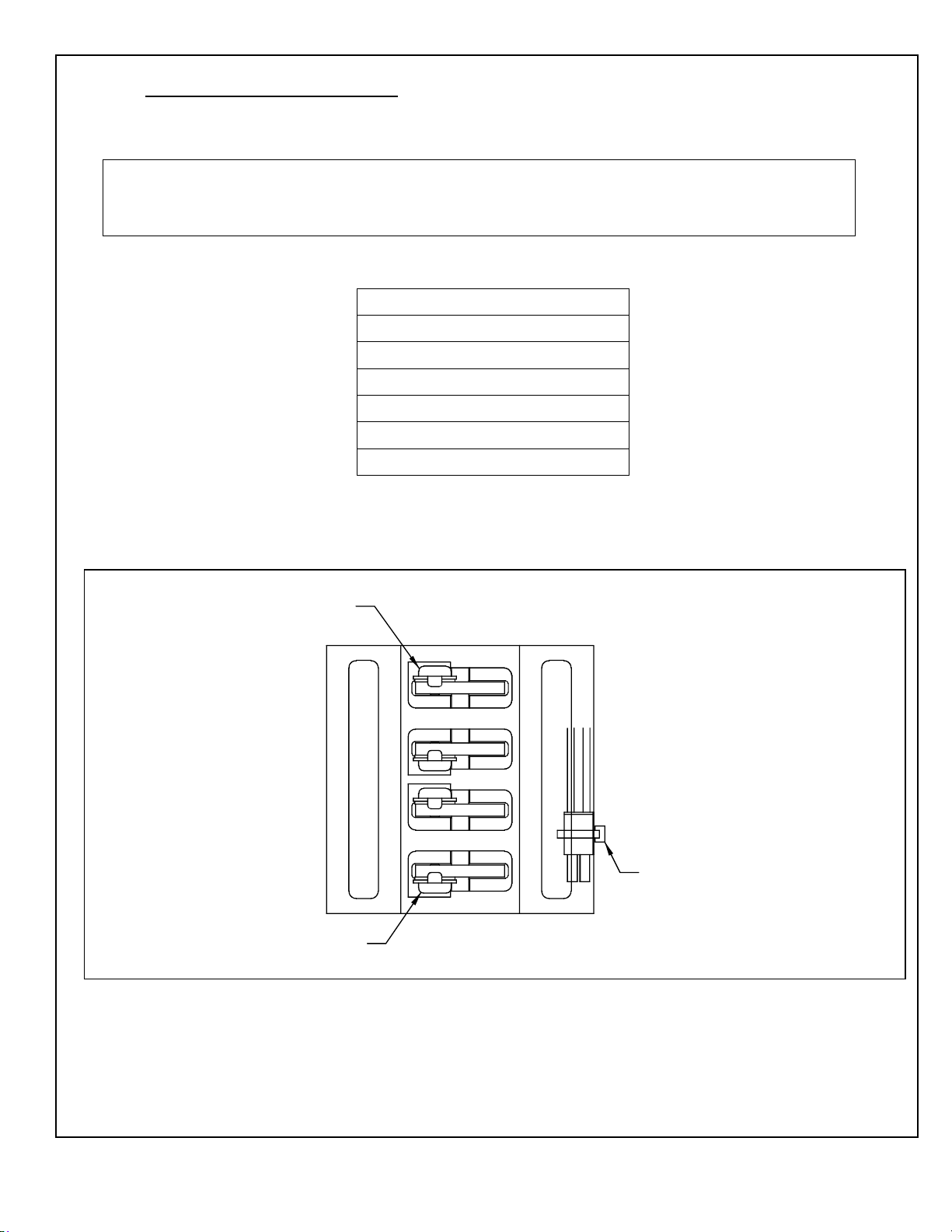
2.1.1 Figure 1 illustrates the 4-Contact Block Assembly.
Figure 1. The 4-Contact Block Assembly
RED WIRE
CONTACT
DE005
GREEN WIRE
CONTACT
BOTTOM VIEW
CABLE TIE
204038
Rev. C, 01/17/12
© 2012, THE STANLEY WORKS. ALL RIGHTS RESERVED. 3 of 19
Page 5
2.2 Header Components
NOTE:
Table 2-2 shows the list of header components for both the DE-MC521 and MC521 Pro controllers.
Table 2-2. Header Components for DE-MC521 and MC521 Pro
Part Name
(EITHER) Terminal Block Assembly
(OR) PC Board I/O Assembly
Buzzer and Bracket Assembly
4-Contact Plate Assembly
(EITHER) DE-MC521 Controller
(OR) MC521 Pro Controller; single or dual motor
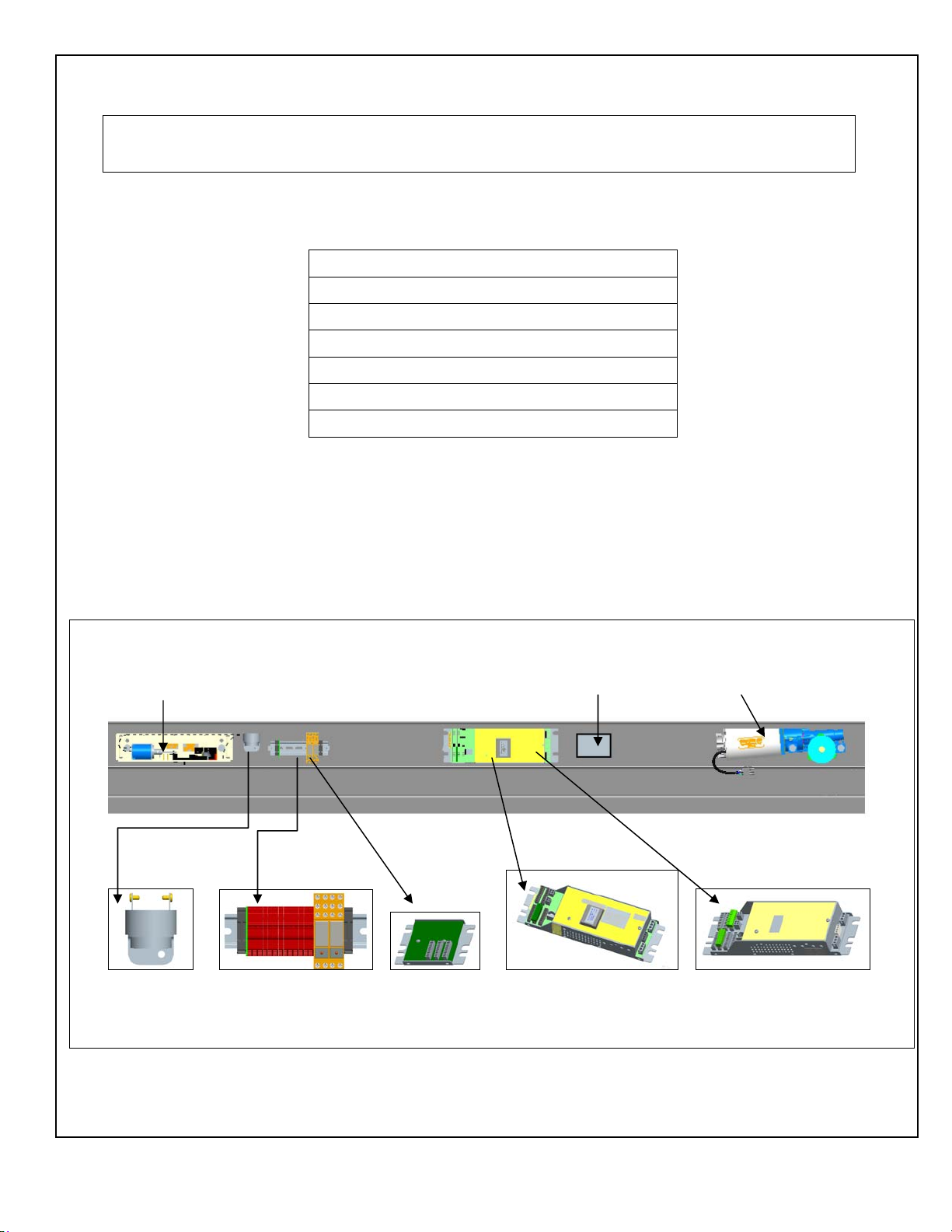
2.2.1 Figure 2 illustrates the (typical) components on the track inside the header:
a. DE-MC521 Controller OR MC521 Pro Controller
b. Terminal Block Assembly OR PC Board I/O Assembly
c. Buzzer and Bracket assembly
2.2.2 SECURE all wire harnesses with cable ties.
Figure 2. DE-MC521 AND MC521 Pro Typical Layout for Components in the Header
Solenoid Lock 24 VDC Power Supply Motor Gear Box
Buzzer Assy. Terminal Assy. OR PC Board DE-MC521 OR MC521 Pro
I/O Assembly
204038
Rev. C, 01/17/12
© 2012, THE STANLEY WORKS. ALL RIGHTS RESERVED. 4 of 19
Page 6

2.3 Installing the Components on the Header Cover or Jamb (if necessary)
2.3.1 INSTALL power key switch assembly as follows:
If installation is a Dura-Glide 3000, Refer to 203926, “Rotary/Key Switch
Instruction Manual,” for machining template and MOUNT power key switch
assembly to header cover.
If installation is a Dura-Glide 2000, Refer to 203926,“Rotary/Key Switch
Instruction Manual,” for machining template and MOUNT power key switch
assembly to header or jamb inside of building.
2.3.2 INSTALL rotary key switch assembly as follows:
If installation is a Dura-Glide 3000, Refer to 203926, “Rotary/Key Switch
Instruction Manual,” for machining template and MOUNT rotary function key
switch assembly to header cover.
If installation is a Dura-Glide 2000, Refer to 203926,“Rotary/Key Switch
Instruction Manual,” for machining template and MOUNT rotary key switch
assembly to header or jamb inside of building.
2.4 The 4-Contact Plate Assembly for Bi-parting Doors
2.4.1 Figure 3 illustrates the 4-contact plate assembly for Bi-parting Doors
Figure 3. The 4-Contact Plate Assembly for Bi-parting Doors
NOTE:
The 4-contact plate assembly must align properly with the two 4-contact switch block assemblies on the
hangers to ensure the transfer of electrical connections to the door panels. The position of the four-contact
switch block assemblies can be adjusted for vertical alignment.
204038
Rev. C, 01/17/12
© 2012, THE STANLEY WORKS. ALL RIGHTS RESERVED. 5 of 19
Page 7

2.4.2 CYCLE the door several times, and ENSURE the 4-contact switch block assemblies on
the hanger leading edges mate properly with the center contact plate as the doors come
together.
2.5 The 4-Contact Plate Assembly for Single-Slide Doors
2.5.1 Figure 4 illustrates the configuration for the left side or right side mounting.
Figure 4. Configuration for Left and Right Side 4-Contact Plate Assembly Mounting
2.5.2 Figure 5 illustrates the 4-contact plate assembly installation for Single Side Doors.
NOTE:
The 4-contact plate must align properly with the four-contact switch block assembly on the hanger to
ensure the electrical connection to the door panel. The position of the four-contact switch block assembly
can be adjusted for vertical alignment.
Figure 5. The 4-Contact Plate Assembly for Single-Slide Doors (Left Side Mounting Shown)
204038
Rev. C, 01/17/12
© 2012, THE STANLEY WORKS. ALL RIGHTS RESERVED. 6 of 19
Page 8

2.5.3 CYCLE the door several times, and ENSURE the 4-contact switch block assembly on
the hanger leading edge mates properly with the center contact plate as the door closes.
2.6 Installing the Label
2.6.1 INSTALL the Delayed Egress label “PUSH UNTIL ALARM SOUNDS. DOOR CAN
BE OPENED IN 15 SECONDS” in the center of the push bar. (If a 30-second egress is
required and approved by fire marshal, ATTACH the “30” sticker on top of the number
“15” in the label.)
2.7 The Delayed Egress Assembly Wiring
WARNING
The I/O & Buzzer connections to the DE-MC521 controller and MC521 Pro controller as indicated on the
Attachment 3 must be made by grounded, shielded cable.
NOTE
For DE-MC521: The input power electrical rating for this assembly is 120-VAC, 60-Hz, and 5A. The
output power electrical rating is 14.7 ~ 20.2 VDC.
For MC521 Pro:The input power electrical rating for this assembly is 120-VAC, 60-Hz, and 5A. The
output power electrical rating is 17.9 ~24 VDC.
2.7.1 Refer to Attachments 2 and 3 for the appropriate delayed egress schematic and system
wiring.
2.8 Operational Checkout of the Delayed Egress System
2.8.1 Refer to appropriate controller installation manual and perform FIS.
a. For DE-MC521 only:
Refer to P/N 204003, “MC521 Installation and Operation
Manual.”
b. For MC521 Pro only:
Refer to P/N 20466, “MC521 Pro Installation and Operation
Manual.”
2.8.2 SET the door for delayed egress as follows:
NOTE
The door can be set for delayed egress using either the pushbuttons or a handheld device. The following
steps describe setting delayed egress using the pushbuttons.
INDEX 18. Value 00 is OFF (not evaluated by UL).
INDEX 18. Value 01 is 15 sec.
INDEX 18. Value 02 is 30 sec.
2.8.3 CYCLE the doors several times and ENSURE the following features function properly:
The 1-second nuisance delay functions properly.
The buzzer alarm sounds.
The 15- or 30-second delay-of-egress period functions properly.
204038
Rev. C, 01/17/12
© 2012, THE STANLEY WORKS. ALL RIGHTS RESERVED. 7 of 19
Page 9

MIN. GAP
NOTE:
The typical gap required between the magnet and the armature is 0.120″.
2.8.4 If shear locks do not engage, refer to Figure 6 and, using the key wrench supplied with
the lock kit, ADJUST the shear lock assembly. After adjusting the armature, remove the
armature and tighten nuts at the bottom. Reassemble.
2.8.5 If necessary, ADJUST the 4-contact switch block assemblies and ENSURE proper
alignment with the center contact plate.
Figure 6. Adjusting the Shear Lock Assembly
MAGNET
ARMATURE
USE SUPPLIED KEY WRENCH TO ADJUST ARMATURE PLATE
TO APPROXIMATELY 0.080" to 0.120" OF GAP BETWEEN MAGNET
SURFACE.
DE003
2.9 Troubleshooting the Delayed Egress System
2.9.1 Refer to Table 2-3 for a listing of symptoms and remedies.
NOTE
The following two conditions describe proper system operation:
1. Door is in CLOSED/LOCKED. The buzzer is OFF. The shear locks are energized. K1 LED is OFF. K2
LED is ON.
2. Door is in AUTOMATIC. The buzzer is OFF. The shear locks are de-energized. K1 LED is ON. K2
LED is OFF.
204038
Rev. C, 01/17/12
© 2012, THE STANLEY WORKS. ALL RIGHTS RESERVED. 8 of 19
Page 10

Table 2-3. Symptoms and Remedy
Symptom Remedy
Door set for CLOSED/LOCKED and door gets to closed position. Delayed
egress starts without pressing push bar. The dE indication is displayed on
MC521 OR MC521 Pro. The buzzer turns ON. K2 LED is OFF. K1 LED
is ON. And shear locks de-energize after 15/30 seconds.
Door set for CLOSED/LOCKED in closed position. Shear locks energize,
but door panel can break out.
Check connections from push bar
switches to two- contact transfer
contacts to quad transfer contacts to
K2 coil.
Adjustment is required on armature.
Set gap to between 0.080″ and 0.120″.
2.9.2 CHECK for correct DC voltage measurements on terminal block OR PC Board
assembly as follows:
a. SET the door to CLOSED/LOCKED.
b. CONNECT the negative (-) lead of the multimeter to TB2-10 of the controller.
c. Refer to Table 3-4, and CHECK each terminal number of the terminal block and
relay assembly for the voltage shown.
Table 2-4. TB2-10 Voltage Checks for DE-MC521 and MC521 Pro with Terminal Block OR PC Board
DE-
MC521
TB2
TB2-10 DE-TB1-1 1 24 - 28
TB2-10 DE-TB1-2 2 24-28
TB2-10 DE-TB1-3 3 24-28
TB2-10 DE-TB1-4 4 24-28
TB2-10 DE-TB1-5 5 24-28
TB2-10 DE-TB1-6 6 24-28
TB2-10 DE-TB1-7 7 24-28
TB2-10 DE-TB1-8 8 NA Wire connection open from TB5-10. Check if MC521 is configured
TB2-10 DE-TB1-9 9 >20 VDC Push bar switch is open. Dual transfer contact is not making
TB2-10 DE-TB1-10 10 0VDC K2 is off.
TB2-10 DE-TB2-1 11 0VDC Wire disconnected from TB5-4.
TB2-10 DE-TB2-2 12 0VDC Wire disconnected from TB5-10.
DE-TB2-3 13 NA NOTE: this is a shield wire connection
PC Board
Terminal
No.
Terminal
Block and
Relay Assy
Correct
Voltage
VDC
VDC
VDC
VDC
VDC
VDC
VDC
Possible Fault if Voltage is Incorrect
The bridge on terminal block (not PC Board) 1-2 is loose.
The 24 VDC power supply disconnected.
The 24 VDC power supply disconnected.
The bridge on terminal block (not PC Board) 2-3 is loose. The 24
VDC power supply is disconnected.
The 24 VDC power supply is disconnected. Fire alarm input is open
or missing.
The bridge on terminal block (not PC Board) 4-5 is loose.
MC521 was selected for fail safe, it should be fail secure.
K1 is defective.
for delayed egress.
connection. Quad
Contact is not making connection.
204038
Rev. C, 01/17/12
© 2012, THE STANLEY WORKS. ALL RIGHTS RESERVED. 9 of 19
Page 11

2.10 Replacement Parts
2.10.1 Refer to Attachment 1 for a listing of replacement parts.
204038
Rev. C, 01/17/12
© 2012, THE STANLEY WORKS. ALL RIGHTS RESERVED. 10 of 19
Page 12

Attachment 1
Replacement Parts
(Sheet 1 of 1)
Description Part Number
Terminal Block and Relay Assembly 517217
PC Board IO Assembly 193648
Buzzer and Bracket Assembly 415109
Power Key Switch Assembly 415119
Power Supply Assembly 417236
4-Contact Block Assembly 516907
4-Contact Plate Assembly 516908
2-Contact Block Assembly 516909
2-Contact Plate Assembly 516910
Shear Magnet Locks 714082
Reset Switch 413584
Push Bar Cartridge with Switch, 27” 185060-1
Push Bar Cartridge with Switch, 16” 185060-2
DE-MC521 Controller Replacement Kit 314063
MC521 Pro Controller Replacement Kit; dual motor only 314117
204038
Rev. C, 01/17/12
© 2012, THE STANLEY WORKS. ALL RIGHTS RESERVED. 11 of 19
Page 13

Attachment 2
Delayed Egress Schematic Diagram
For Terminal Block with EITHER DE-MC521 OR MC521 Pro Controllers
(Sheet 1 of 2)
204038
Rev. C 01/17/12
Page 12 of 19
© 2012, THE STANLEY WORKS. ALL RIGHTS RESERVED.
Page 14

Attachment 2
Delayed Egress Schematic Diagram
For PC Board with EITHER DE-MC521 OR MC521 Pro Controllers
(Sheet 2 of 2)
204038
Rev. C 01/17/12
Page 13 of 19
© 2012, THE STANLEY WORKS. ALL RIGHTS RESERVED.
Page 15

Attachment 3
Delayed Egress Wiring Diagram – Terminal Block and Relay Ass’y for DE-MC521 and MC521 Pro Controllers
(Sheet 1 of 6)
204038
Rev. C 01/17/12
Page 14 of 19
© 2012, THE STANLEY WORKS. ALL RIGHTS RESERVED.
Page 16

Attachment 3
Delayed Egress Wiring Diagram – PC Board for DE-MC521 and MC521 Pro
(Sheet 2 of 6)
204038
Rev. C 01/17/12
Page 15 of 19
© 2012, THE STANLEY WORKS. ALL RIGHTS RESERVED.
Page 17

Attachment 3
Delayed Egress Wiring Diagram
(Sheet 3 of 6)
FIELD TERMINAL BLOCK WIRING
204038
Rev. C 01/17/12
Page 16 of 19
© 2012, THE STANLEY WORKS. ALL RIGHTS RESERVED.
Page 18

Attachment 3
Delayed Egress Wiring Diagram
(Sheet 4 of 6)
FIELD PC BOARD WIRING
204038
Rev. C 01/17/12
Page 17 of 19
© 2012, THE STANLEY WORKS. ALL RIGHTS RESERVED.
Page 19

Attachment 3
Delayed Egress Wiring Diagram
(Sheet 5 of 6)
FIELD CONTROLLER WIRING
204038
Rev. C 01/17/12
Page 18 of 19
© 2012, THE STANLEY WORKS. ALL RIGHTS RESERVED.
Page 20

Attachment 3
Delayed Egress Wiring Diagram
(Sheet 6 of 6)
FIELD POWER SWITCH WIRING
204038
Rev. C 01/17/12
Page 19 of 19
© 2012, THE STANLEY WORKS. ALL RIGHTS RESERVED.
 Loading...