

Page 1
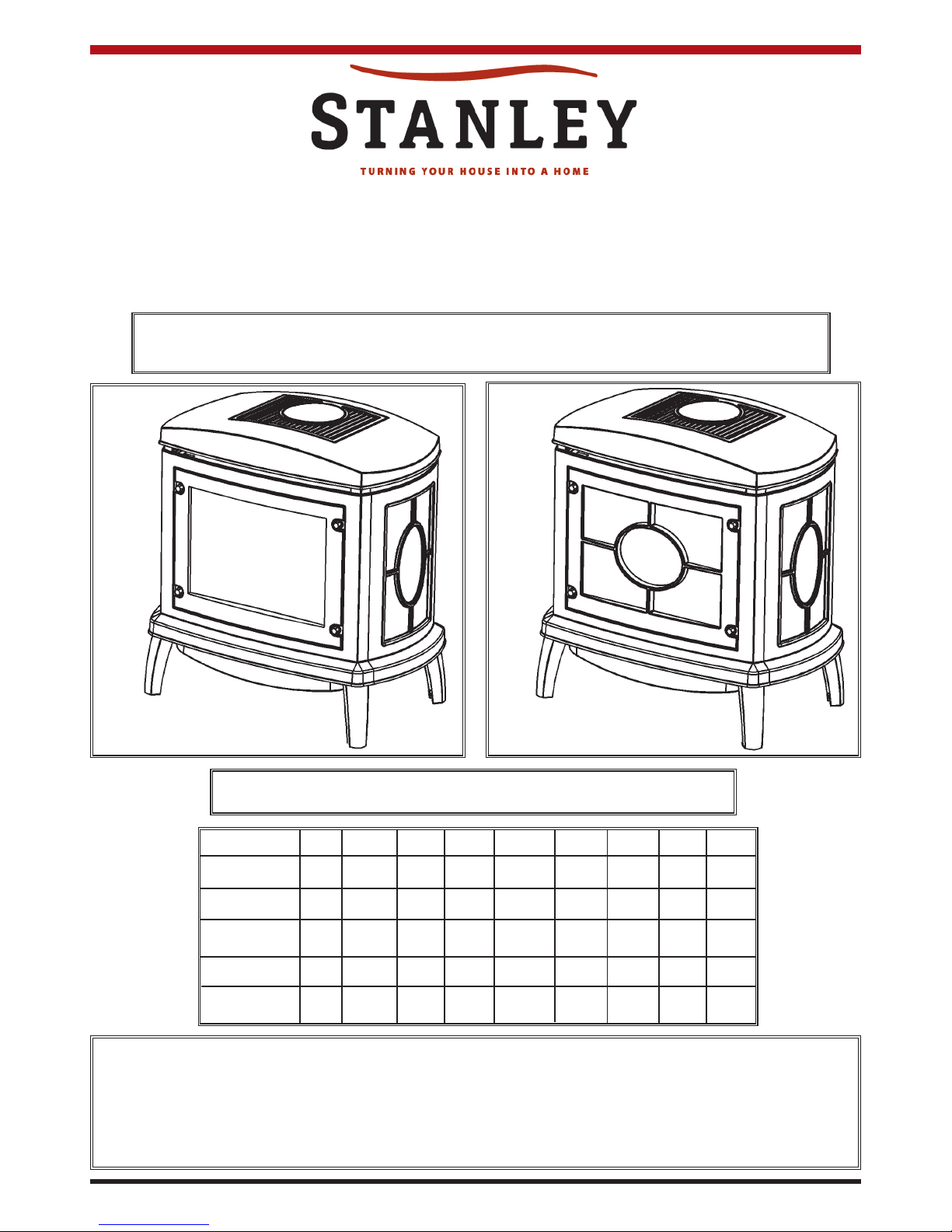
MAEVE
STOVE RANGE
Operation, Installation & Servicing Instructions
IMPORTANT
Please read these instructions carefully and keep them in a safe place.
They will be needed when servicing this appliance.
STOVES REQUIRED TO HAVE THE GRILL OPTION MUST BE
ORDERED AS THEY ARE FACTORY FITTED.
STANDARD FLUE MEDIUM MAEVE STOVE
WITHOUT GRILL
STANDARD FLUE MEDIUM MAEVE STOVE
WITH GRILL
Country AT BE DK FI FR DE GR IS IE
Natural Gas
***** *
LPG **** **
Country IT LU NL NO PT ES SE GB
Natural Gas *** ****
LPG * ******
WARNING
Do not attempt to burn rubbish in this stove. This stove must only be operated with the door secured firmly
in position. The outer casting of this stove will become hot whilst in operation, it is therefore recommended
that the appliance be guarded to protect the young and infirm using a suitable fire guard. Ensure that fabrics
such as curtains are not positioned above or near to the stoves outer casting.
KEEP THESE INSTRUCTIONS IN A SAFE PLACE
Page 2
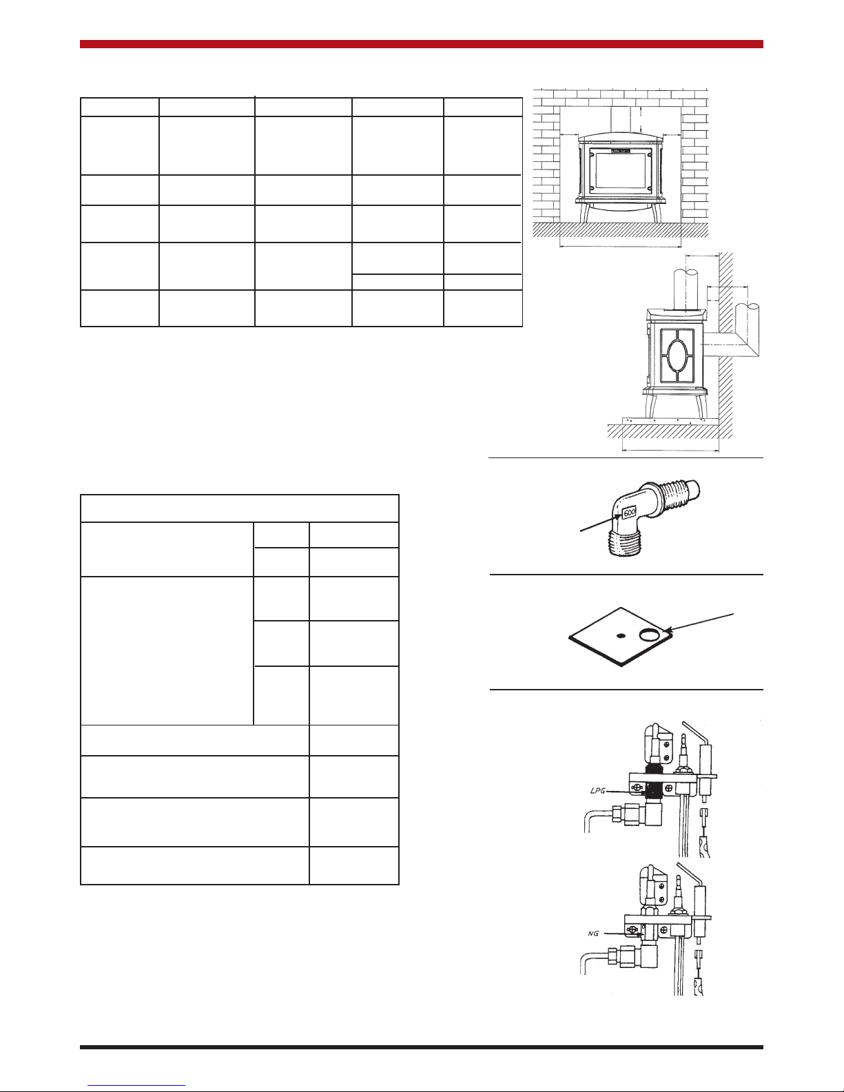
GAS CAT. GAS TYPE PRESSURE INPUT kW COUNTRY
AT, DK, ES,
I2 H G20 20MB 6.60 Gross FI, GB, IE, IT,
PT, SE.
I2L G25 25MB 6.00 Gross NL
I2E+ G20 20MB 5.94 Nett BE, FR
G25 25MB
ES, IT, IE
I3+ G30 29MB 6.25 Gross GB, PT
G31 37MB 5.62 Nett BE, FR
I3B/P G30 29MB 6.25 Gross DK, FI, IS
G31 NL, NO, SE
TECHNICAL SPECIFICATION
MEDIUM
INJECTOR SIZE NG 400
LPG 170
AERATION SIZE Ø
NG 11mm
Ø
I
2L 8mm
Ø
LPG 15.5 x 2
EFFICIENCY CLASS II
FLUE T.T.B SENSOR 100
o
C
FLUE OUTLET SIZE Ø
127mm
INLET CONNECTION SIZE Ø
8mm
150
150
225
1007
127
50
470
1
Fig.1
Fig.2
Fig.3
Fig.4
Fig.5
Fig.6
176
Page 3

1. GENERAL
1.1 Installation and servicing must only be
carried out by a competent person.
1.2 In all correspondence, please quote the
appliance type and serial number which
can be found on the data badge located at
the rear of the stove.
1.3 Ensure that curtains are not positioned
above the stove, and that there is at least
a clearance of 300mm between the sides
of the stove and any curtains.
1.4 If any cracks are observed in the glass
panel, do not use the appliance until the
glass has been replaced.
2. LIGHTING THE STOVE
2.1 Ensure the control is pointing to the off
2.2 Depress control knob and rotate anticlockwise until a click is heard and the
knob is pointing at the ignition symbol (
*
),
the pilot should now be lit.
2.3 Depress for 5 to 10 seconds and then
release, the pilot should remain alight. If
the pilot does not light, repeat the above
procedure.
2.4 If it will not light after repeated attempts,
contact the retailer or installer from whom
the appliance was purchased.
2.5 The appliance may now be turned to the
high position to ignite the main burner,
then controlled between high and low as
desired.
3. TURNING THE STOVE OFF
3.1 Depress the control knob and turn clockwise until the knob is pointing at the off
NOTE: THE YELLOW FLAMES WILL
APPEAR WHEN THE FIRE HAS GAINED
SUFFICIENT HEAT - TYPICALLY 10 TO
20 MINUTES.
IF THE APPLIANCE IS EXTINGUISHED
OR GOES OUT IN USE, WAIT 3 MINUTES BEFORE ATTEMPTING TO RELIGHT THE APPLIANCE.
4. CLEANING THE STOVE
4.1 Remove the ceramic coals and place on a
dry, clean surface. Remove the front coal
ceramic, please handle with care.
4.2 Clean the flame baffle ceramic piece and
burner using a vacuum cleaner with soft
brush attachment, ensure all debris are
removed from the burner ports.
4.3 Replace the ceramics by referring to
Section 5.
5. ARRANGEMENT OF FUEL-BED COMPONENTS
The major ceramic components can be
found inside the firebox, remove the cast
iron door and remove all the protective
packaging from these components.
NOTE: THE CAST IRON DOOR IS
HEAVY, TAKE EXTREME CARE WHEN
HANDLING.
The loose coals should be arranged as
specified in the following steps, care
should be taken to ensure that there is
sufficient space between the coals to
allow flames to pass through.
5.1 Place the flame baffle onto the shelf at the
rear of the tray and push up against the
rear ledge, see Fig 11.
5.2 Locate the front coal moulding in front of
the flame baffle ensuring that the end legs
sit flat against the burner skin, see Fig 12.
5.3 Place three large coals on the front coal
so that they lean against the flame baffle,
and four large coals on the flame baffle so
that they sit on the fingers, see Fig 13.
5.4 Place two small coals at each end of the
front coal so that they lean against the
flame baffle, and a further two large coals
on the flame baffle, one at each end, see
Fig 14.
5.5 Place five small coals along the rear of
the flame baffle, resting against the rear
ledge, see Fig 15.
NOTE: ENSURE THAT THE COALS ARE
POSITIONED, AS DETAILED ABOVE.
ONLY USE THE CORRECT AMOUNT OF
COALS, AS SPECIFIED IN THE DIAGRAMS.
INSTRUCTIONS FOR USE
2
position (
).
position (
).
Page 4

6. THE FLAME FAILURE DEVICE
6.1 This is a safety feature incorporated in all
WATERFORD fires which automatically
switches off the gas supply if the pilot
light goes out and fails to heat the thermocouple.
7. 'RUNNING IN'
7.1 The surface coating on the coals used in
your WATERFORD fire will "burn off" during the first few hours of use, producing a
harmless and temporary odour. This will
disappear after a short period of use. If
the odour persists, ask your installer for
advice.
8. SERVICING
8.1 The fire must be serviced every 12
months by a qualified Gas Engineer. In all
correspondence, always quote the appliance type and the serial number, which
may be found on the data badge.
9. ENAMEL CLEANING
General cleaning must be carried out when the
stove is cool.
If this stove is finished in a high gloss vitreous
enamel, to keep the enamel in the best condition
observe the following tips:
9.1 Wipe over daily with a soapy damp cloth,
followed by a polish with a clean dry
duster.
9.2 For stubborn deposits a soap impregnated
pad can be carefully used on the vitreous
enamel.
9.3 Use only products recommended by the
Vitreous Enamel Association, these products carry the vitramel label.
9.4 DO NOT USE ABRASIVE PADS OR
OVEN CLEANSERS CONTAINING CIT
RIC ACID ON ENAMELLED SURFACES.
ENSURE THAT THE CLEANSER MANU
FACTURERS INSTRUCTIONS ARE
ADHERED TO.
3
ASSOCIATION
Page 5

NOTE: IF IT IS INTENDED TO FIT THE
STOVE INTO AN EXISTING BRICK
CHIMNEY, A 127mm LINER MUST BE
USED.
2.2 The minimum effective height of the flue or
chimney must be 3 metres (10ft).
2.3 The chimney or flue must be free from any
obstruction. Any damper plates should be
removed or secured in the fully open position, and no restrictor plates should be fitted.
2.4 The chimney should be swept immediately
prior to the installation of the appliance.
However, where it can be seen that the
chimney is clean and unobstructed
through-out its entire length, it need not be
swept.
3. VENTILATION & COMBUSTION AIR
REQUIREMENTS
This stove has a heat input of less than 7 kW and
therefore does not normally require any additional
ventilation. However, consideration must be given
to the local rules in force.
3.1 Any air vent must either be connected
direct to an outside air supply or to adja
cent rooms having a permanent vent to
the outside.
3.2 If there is another combustion appliance
fitted in the same or adjacent room, it will
be necessary to refer to the rules in force
to calculate the additional air supply.
3.3 If there is an air extraction fan fitted in the
room or adjacent rooms where this appliance is fitted, additional air vents may be
required to elleviate the possibility of
spillage of products of combustion from
the appliance/flue while the fan is in operation. Refer to the rules in force.
3.4 Where such an installation exists, a test for
spillage should be made with the fan or
fans and other gas burning appliances in
operation at full rate.
3.5 If spillage occurs following the above operation, an additional air vent of sufficient
size to prevent this occurrence should be
installed.
4. INSTALLATION OF THE GAS SUPPLY
4.1 Before installation, ensure that the local
distribution conditions (identification of
the type of gas and pressure) and the
adjustment of the appliance are compatible.
IMPORTANT: ENSURE THAT THE APPLI
ANCE IS CORRECTLY ADJUSTED FOR
THE GAS TYPE AND CATEGORY
APPLICABLE IN THE COUNTRY OF USE.
REFER TO DATA BADGE AND TECHNI
CAL SPECIFICATIONS AT THE FRONT
OF THE BOOKLET.
FOR DETAILS OF CHANGING BETWEEN
GAS TYPES, REFER TO SECTION 18.
1. SAFETY PRECAUTIONS
1.1 This appliance must be installed in accordance with the rules in force, and used
only in a sufficiently ventilated space.
Please read these instructions before
installation and use of this appliance.
1.2 These instructions must be left intact with
the user.
1.3 Do not attempt to burn rubbish in this
appliance.
1.4 In your own interest, and those of safety,
this appliance must be installed by competent persons in accordance with local
and national codes of practice. Failure to
install the appliance correctly could lead to
prosecution.
1.5 Keep all plastic bags away from young
children.
1.6 Do not place any object on or near to the
stove. Allow adequate clearance above
the stove. See Figs 7, 8, 9.
1.7 The stove is fitted with the Waterford Flue
T.T.B System which will act to cut off the
gas supply to the appliance in the event of
incorrect operation of the flue. If the system acts to shut off the gas supply, this
indicates that there is insufficient flue pull.
Continued operation of this safety device
means that there may be a serious problem with the flue system, and this should
be inspected by a qualified gas engineer.
Do not use the stove until an engineer
says it is safe to do so.
The Waterford T.T.B System must not be
tampered with. Use only genuine
Waterford replacement parts when servic
ing the system - refer to section 16.
2. FLUE AND CHIMNEY REQUIREMENTS
2.1 The chimney or flue system must comply
with the rules in force, and must be a minimum of 127mm (5”) in diameter.
INSTRUCTIONS FOR INSTALLATION & SERVICING
4
Page 6

4.2 Ensure that the gas supply is capable of
delivering the required amount of gas, and
is in accordance with the rules in force.
4.3 Soft copper tubing and soft soldered joints
can be used but must not be closer than
50mm (2”) to the base of the tray.
4.4 A means of isolating the gas supply to the
appliance must be provided independent of
any appliance control.
4.5 All supply gas pipes must be purged of any
debris that may have entered, prior to connection to the appliance.
5. APPLIANCE LOCATION
5.1 This appliance must stand on a non-combustible hearth that is at least 12mm thick;
the minimum dimensions are shown in
Fig.7.
5.2 This appliance must not be installed in a
room that contains a bath or shower.
5.3 This stove is not suitable for installation
onto a combustible wall; all combustible
materials must be removed from the area
behind the stove.
5.4 Ensure that all clearances to combustible
materials are complied with, in particular,
there must be 50mm clearance to any rear
wall and 150mm either side of the stove. If
there is any combustible materials directly
above the unit, a minimum distance of
225mm must be maintained. See Fig. 8 &
9.
NOTE: ATTENTION MUST BE GIVEN TO
ALLOWING ADEQUATE CLEARANCE
AT THE SIDES AND REAR OF THE
STOVE, SO THAT A SPILLAGE TEST
CAN BE PERFORMED.
6. INSTALLATION OF THE STOVE
6.1 Remove the outer carton, take the stove off
the pallet, and remove the accessory carton. It will now be necessary to decide
upon top or rear flue exit, the stove is factory built for rear flue exit, but it may be
changed to top exit by simply interchanging
the flue spigot and blanking plate located
on the stove.
6.2 Position the stove ensuring all appropriate
clearances are observed.
NOTE: THE STOVE LID IS LOOSE, BE
CAREFUL WHEN MOVING THE UNIT.
6.3 Having run the gas supply to the stove,
PURGE THE SUPPLY PIPE, this is essential to expel any debris that may block the
gas controls. Connect the gas supply to
the 8mm-compression elbow at the right
hand rear corner of the stove, see Fig.10.
6.4 Check the pull of the flue system by applying a lighted smoke pellet to the flue system opening. If there is a definite flow into
the chimney, proceed with the installation,
if not; warm the chimney for a few minutes.
IF THERE IS STILL NO DEFINITE FLOW,
THE FLUE MAY REQUIRE ATTENTION SEEK EXPERT ADVICE.
6.5 The flue system may now be connected to
the stove, ensure that all joints are sealed
with a suitable fire resistant sealant. It is
also recommended that a physical retention method be used at the flue spigot joint,
self-tapping screws being favoured.
6.6 Connect a suitable pressure gauge to the
test point located on the inlet fitting, and
turn the gas supply on. Light the appliance
and check all gas joints for possible leaks.
Turn the appliance to maximum and check
that the supply pressure is as stated on the
data badge. Turn the gas off and replace
the test point screw, turn the gas on and
check the test point for leaks.
7. FUELBED ARRANGEMENT
The major ceramic components can be
found inside the firebox, remove the cast
iron door using the tool provided, and
remove all the protective packaging from
these components.
NOTE: THE CAST IRON DOOR IS
HEAVY, TAKE EXTREME CARE WHEN
HANDLING.
The loose coals should be arranged as
specified in the following steps, care
should be taken to ensure that there is sufficient space between the coals to allow
flames to pass through.
7.1 Place the flame baffle onto the shelf at the
rear of the tray and push up against the
rear ledge, see Fig. 11.
7.2 Locate the front coal moulding in front of
the flame baffle ensuring that the end legs
sit flat against the burner skin, see Fig.12.
7.3 Place three large coals on the front coal so
that they lean against the flame baffle, and
four large coals on the flame baffle so that
they sit on the fingers, see Fig.13.
7.4 Place two small coals at each end of the
front coal so that they lean against the
5
Page 7

flame baffle, and a further two large coals
on the flame baffle, one at each end, see
Fig. 14.
7.5 Place five small coals along the rear of the
flame baffle, resting against the rear ledge,
see Fig. 15.
NOTE: ENSURE THAT THE COALS ARE
POSITIONED, AS DETAILED ABOVE.
ONLY USE THE CORRECT AMOUNT OF
COALS, AS SPECIFIED IN THE
DIAGRAMS.
7.6 Ensure that the fibreglass seal on the back
of the door is intact, locate the door on the
four studs and slide back to the firebox.
Secure in place using the four brass dome
nuts, do not overtighten the nuts. See
Fig.17.
NEVER OPERATE THE STOVE WHEN
THE DOOR IS REMOVED.
7.7 The top flue blanking plate is fitted to the
stove (see Fig.16). If rear exit is chosen,
top blanking plate must be kept in place.
8. COMMISSIONING
NOTE: LIGHTING INSTRUCTIONS ARE
GIVEN IN SECTION 2 OF THE INSTRUCTIONS FOR USE CHAPTER.
8.1 Close all openable doors and windows in
the room, ignite the stove and operate on
maximum for 5 minutes. Position a lighted
smoke match just inside the draught diverter opening and check that all the smoke is
drawn into the opening, see Fig.18. If
there is any doubt, run the stove for a further 10 minutes, and repeat the test.
8.2 If there are any extractor fans in the room
of adjacent rooms, the test must be repeated with the fans running on maximum.
IF SPILLAGE PERSISTS, DISCONNECT
THE APPLIANCE AND SEEK EXPERT
ADVICE.
SERVICING
9. GENERAL
9.1 This appliance must be serviced at least
once a year by a competent person.
9.2 All principal components can be replaced
without removing the stove from its installation, although it is essential that the gas
supply to the appliance is turned off at the
isolation device before proceeding further.
10. PILOT UNIT
10.1 Turn the gas supply off at the isolation
6
device, remove the door and place to one
side, carefully remove the ceramic fuelbed
components.
10.2 Undo the pilot compression nut, remove
the ignition lead from the electrode by gently pulling downwards, and undo the thermocouple from the back of the gas valve ,
see Fig 19. Undo the main injector
compression nut and pull pipe clear of the
injector, see Fig 23.
10.3 Remove the two pozidriv screws which
retain the burner and remove the burner
unit, see Fig 20. Remove the two screws
holding the heat shield in place to
reveal the pilot unit.
10.4 Remove the two screws holding the pilot,
and replace with a new unit. Replace the
heat shield and secure the burner unit in
position ensuring that the front of the tray
sits on top of the tabs at the sides of the
firebox. Reconnect the thermocouple, ignition lead and pilot pipe, turn the gas supply
on and check the joints for any leaks.
10.5 Replace the ceramic components by refer
ring to Section 7, replace the door and
secure in position.
11. IGNITION LEAD AND PIEZO
Due to the method of manufacture, these
components can only be replaced as an
integral unit.
11.1 Turn the gas supply off at the isolation
device. Pull the control knob off the gas
valve spindle to reveal the piezo securing
screw access holes. Using a small pozidriv
screwdriver, remove the two screws, see
diagram 26.
11.2 Pull the piezo body down and remove from
the valve, disconnect the ignition lead from
the electrode, see diagram 24.
11.3 Replace the assembly with a new unit, refit
the screws and connect the ignition lead to
the electrode. Check the operation of the
new piezo, turn the gas supply on and with
the pilot running, check for leaks, especially where the two halves of the valve join.
Replace the control knob.
NOTE: WHILST PERFORMING THE
PIEZO REPLACEMENT, YOU WILL BE
BREAKING THE SEAL BETWEEN THE
TOP AND BOTTOM HALVES OF THE
VALVE. ENSURE THAT THIS JOINT IS
CORRECTLY SECURED AND LEAK
TESTED.
Page 8

12. GAS FILTER
The gas filter is located just inside the inlet
boss of the control valve, to replace the filter, proceed as follows:
13.1 Turn the gas supply off at the isolation
device. Undo the inlet compression nut
and pull the pipe clear of the valve, see Fig
22. Prise the small retaining ring out and
remove the filter.
13.2 Replace with a new filter and push into
position ensuring that it sits on the shoulder, replace the retaining ring and push into
position.
13.3 Replace the inlet pipe, turn the gas supply
on and check for leaks.
14. MAGNETIC SAFETY VALVE
14.1 Turn the gas supply off at the isolation
device. Undo the thermocouple connection from the back of the gas valve, pull the
sensor leads clear and remove the interruptor block.
14.2 Undo the mag valve retaining nut at the
back of the control valve, gently tap out the
mag valve and replace with a new unit.
Replace the retaining nut and tighten, see
Fig.22.
14.3 Reassemble the interrupter block and
leads, secure in place with the thermocouple. Turn the gas supply on and check the
entire pipework and valve joints for any
leaks.
15. MAIN INJECTOR
15.1 Turn the gas supply off at the isolation
device. Locate the main injector on the left
hand side of the airbox, undo the compression nut and pull the pipe clear of the injector body, see Fig.23.
15.2 Rotate the injector until it is fully removed,
and install the correct replacement injector.
Reassemble and turn the gas supply on,
check for any leaks.
16. WATERFORD FLUE T.T.B SYSTEM
If the stove has been installed in a restrictive location, it may be necessary to
remove the stove from its location.
16.1 Locate the sensor in the draught diverter
opening, and gently pull the two wires off
the terminals. Undo the two taptite screws
and remove the sensor and the two plastic
spacers, see Fig.24.
16.2 Refit a new sensor ensuring that the spacers are located between the sensor and the
bracket, replace the two leads.
7
If it has been necessary to remove the
stove, ensure that all disturbed gas joints
are leak tested when reinstalled, and
repeat the flue clearance test as detailed in
section 9.
17. PRIMARY AERATION PLATE
17.1 Turn the gas supply off at the isolation
device.
17.2 Locate the aeration plate on the underside
of the airbox and remove the Nyloc nut,
see Fig.25.
17.3 Remove the plate and replace with the correct size, ensure that the hole(s) in the
plate align correctly with the holes in the
underside of the airbox and replace the
Nyloc nut.
18. CHANGING BETWEEN GAS TYPES
In order to change between gas types, it
will be necessary to change the following
items:
* Pilot Unit
* Control Valve
* Injector
* Aeration Plate
* Data Badge
The relevant parts can be ordered from the
parts list, always quote the appliance type
and serial number when ordering spare
parts.
19. SHORT SPARES LIST
Component Medium
Stove
NG LPG
Pilot Unit P10036 P10037
Injector IN0007 IN0006
Aeration Plate ME1096 ME0834
Gas Valve GC0056**
Flue Sensor EL0001
Sensor Lead EL0064
Interrupter GC0026
Mag Unit GC0016
Piezo and GC0062
Ignition Lead
Gas Filter GC0065
Rear Panel -
Flame Baffle CE0120
Front Coal CE0124
Coal Set CE0136
Note: The Control Valve is Factory preset for the
correct gas type and model, a new unit will need to
be ordered when changing between gas types.
Page 9

FAULT CAUSE POSSIBLE REMEDY
Pilot will not light Various Refer to Ignition
Functional Check 1
No Spark Various Refer to Ignition
Functional Check 2
Pilot will not stay lit or goes Various Refer to Flame Failure
out in use Check 2-
Stove goes out while Flue blockage Insufficient flue pull or
warming or in operation Sensor has been activated partial blockage - flue must be
checked by an engineer.
Uneven flame pattern Ceramics not Check front coal and flame
positioned correctly baffle are positioned as shown
in Section 7.
Coals not laid correctly The coals may require slight
adjustment, see Section 7.
Debris in burner Clean burner ports, refer to
ports Users Manual for guidance.
Blue Flame Warming Up Stove will burn blue until run
ning temperature has been
achieved - typically 20 minutes.
Aeration plate Ensure that the aeration plate
is tight and sits flat.
Insufficient gas pressure Check the gas pressure and
correct if necessary.
Airbox QC label removed Ensure QC seal on front of air-
box is correctly sealed.
Low flame height Blockage in supply pipe Disconnect pipe and purge,
ensure no debris has entered
the stove pipework.
Blocked gas filter Replace filter - refer to
Section 12
Insufficient gas pressure Check the gas pressure and
correct if necessary.
Empty supply tank or LPG only - ensure adequate
clylinder supply of gas in cylinders.
Short pilot flame length (see Insufficient gas Check the gas pressure and
diagram 26) pressure correct if necessary.
Blocked pilot flame Replace Unit - refer to section 10
IGNITION FUNCTIONAL CHECK 1
PILOT WILL NOT LIGHT
Ensure there is no debris around the pilot assembly e.g. coal, soot, etc
which could short the spark, clean the area.
There is a blockage in the system, check the inlet test point, the mag
seating, valve and pilot filter.
Operate the valve.
Is there a spark?
Is the control being
operated correctly?
Consult users book
and retry
Will the pilot light
with a match?
Is the gas turned on to
the appliance?
Check isolation tap and
gas meter, retry
Correct and retry.
Is the gas pressure
correct?
Has the system got any
air in it?
Purge the gas pipes
and retry.
GO TO THE NEXT
CHART IGNITION
FUNCTIONAL CHECK
SYSTEM OK
Ensure gap between
electrode and thermo-
couple is 3.5mm and
retry. If the gap is OK
then first change the
ignition lead and retry, if
still no good then change
the piezo.
Does the pilot light?
YES
YES
NO
NO
YES
YES
YES
NO
YES
NO
NO
NO
YES
NO
8
Page 10

IGNITION FUNCTIONAL CHECK 2
NO SPARK
Ensure there is no debris around the pilot assembly e.g. coal, soot, etc
which could short the spark, clean the area.
From Ignition Fault
Finding Chart Pt 2
Is the valve being
operated correctly?
Operate the valve to light
the pilot, does the valve
‘click?
Reset the electrode
gap, retry.
Correct and retry.
Has ignition lead
become detached or is
connection poor?
Remove the electrode
lead from electrode with
insulated pliers hold the
tip 3.5mm from the pilot
pipework, is there a
spark when the valve
‘click’?
Check for defective or damaged
control knob spindle or cam
operation. Check for correct
location of piezo components.
Correct and retry
Remove the electrode lead from
the piezo. Operate the valve.
Does a spark jump from the
piezo to the valve body?
Is the electrode wire
detachable from piezo in
the valve?
Replace the combined
lead and piezo, retry.
Replace the pilot unit
Replace the electrode
lead and retry
Replace the piezo and
retry.
Is the gap between
electrode and
Thermocouple 3.5mm?
Consult the users
instructions, retry.
NO
YES
YES
YES
NO
NO
NO
NO
YES
YES
YES
YES
NO
FLAME FAILURE FUNCTIONAL CHECK
PILOT WILL NOT STAY LIT OR FIRE GOES OUT IN USE
If the appliance goes out in use continually, this may mean that
the Waterford Flue T.T.B System has been activated. The
appliance should not be used until the cause has been found
and rectified.
Ensure there is no debris around the pilot assembly, e.g. coal,
soot, etc which could short the spark, clean the area.
Light the pilot and keep the control knob pushed in at least 10
seconds before letting go.
With the fire
running on full is
the gas at the
pressure started
on the data
badge?
Will pilot
stay alight?
With the pilot running
is the gas pressure as
stated on the data
badge?
Is the pilot flame
of the correct
length?
See Diagram 26
Problem is with
the pipework or
fittings which
lead to the fire.
Correct and
retry.
Is thermocouple
connection good
in back of valve
Run for 3 mins, turn off,
time interval until mag
unit shuts with a click.
Is this greater than 7
seconds?
Change the
pilot unit
Replace pilot unit
will pilot stay alight?
Change mag unit
Tighten the
connection and retry.
SYSTEM OK
Run for 3 mins,
turn off, time
interval until
mag unit shuts
with a click. Is
this greater than
7 seconds?
NO
NO
NO
NO
NO
NO
NO
NO
YES
YES
YES
YES
YES
YES
9
Page 11

AB
Medium 1007 470
A = 225mm
B = 150mm
A = 50mm
B = 150mm
10
DIAGRAMS
Fig.7
Fig.8
Fig.9
Page 12

11
Fig.10
Fig.11
Fig.12
Fig.13
Fig.15
Fig.14
COAL LAYOUT
Page 13

12
Fig.16
Fig.17
Fig.18
Page 14

13
Fig.19
Fig.21
Fig.20
Page 15

14
Fig.22
Fig.23
Fig.24
Fig.26
Fig.25
Page 16

Rev: 004 DP 070129
INSTALLATION CHECK LIST
Flue System
1. The flue height should not be less than 3 metres and no more than 11 metres.
2. If connecting to an existing chimney, the appliance should be connected to a 125mm (5”)
diameter continuous, rigid or flexible flue pipe that terminates in excess of 0.6 metres from
the nearest point on the roof measured vertically, and in excess of 2.3 metres measured
horizontally.
3. If using an external flue, the appliance should be connected to a 125mm (5”) diameter rigid
insulated flue pipe that terminates in excess of 0.6 metres from the nearest point on the
roof measured vertically and in excess of 2.3 metres measured horizontally.
4. Any horizontal flue sections should not exceed 300mm (12”).
5. The chimney serving this appliance should not serve any other appliance.
6. A suitable flue terminal should be fitted at the flue termination point.
7. If using an internal flue or chimney, closure-clamping plates should be used to seal the top
& bottom of the chimney.
8. Access should be provided to the chimney serving the appliance to allow for cleaning.
9. If the flue passes through a combustible wall, a twin wall insulated connector must be used
and come flush to the external surface of the wall.
10. The flue should be capable of producing a continuous draught of between 0.06” w.g. during
normal operation.
Location
1. Clearance to combustible materials must be adhered to as described in the Clearance to
Combustibles section.
2. The stove should be installed as to allow adequate air circulation around the stove and to
allow access for installation & servicing.
3. The stove must be installed on a non-combustible insulated floor protector that covers the
area of 1007mm x 470mm around and under the stove.
Ventilation & Combustion Air Requirements
1. The room in which the appliance is located should have an air vent of adequate size to
support correct combustion, including all other air using devices fitted in the same or
adjacent rooms. (see Ventilation & Combustion Air Requirement Section for specific details).
Gas Supply
1. A 8mm rigid gas supply pipe must be used to connect directly from the gas meter to the stove.
In the event of a number of appliances using the same supply pipe, the pipe size may need
to be increased.
2. A shut off valve must be used to connect the gas supply as close as possible to the stove and
should be accessible at all times.
3. A soundness test must be conducted to check all joints for gas tightness.
Tick
√
15
Manufactured by
Waterford Stanley Ltd.,
Unit 210, IDA Industrial Estate, Cork Road,
Waterford, Ireland.
Tel: (051) 302300 Fax (051) 302315
 Loading...