

Page 1
K1700 & K2300
Wood Pellet Boiler Stove
Installation and Operating Instructions
Read these instructions carefully before installing, using and servicing the stove.
Page 2

Table of Contents
1 SETTING THE LANGUAGE FOR THE FIRST TIME. ................................................................................................................. 3
2 STANLEY PELLET STOVE WARRANTY .................................................................................................................................. 4
3 PACKAGE CONTENT ........................................................................................................................................................... 5
3.1 U
4 SAFETY PRECAUTIONS ....................................................................................................................................................... 5
4.1 F
5 TECHNICAL SPECIFICATIONS .............................................................................................................................................. 7
6 INSTALLATION OF THE BOILER PELLET STOVE .................................................................................................................... 9
6.1 A
7 INSTALLATION REQUIREMENTS ....................................................................................................................................... 11
7.1 I
7.2 I
7.3 I
7.4 H
8 FUEL ................................................................................................................................................................................ 13
9 USE OF THE BOILER PELLET STOVE ................................................................................................................................... 14
NPACKING THE FREE-STANDING FIRE
OR YOUR SAFETY, WE RECOMMEND THAT
SSEMBLY OF REMOVABLE PARTS
NSTALLATION OF DUCTS AND FUME EXTRACTION SYSTEMS
NSTALLATION WITHOUT A CHIMNEY
NSTALLATION WITH A CHIMNEY
YDRONIC INSTALLATION
................................................................................................................................................... 13
..................................................................................................................................... 5
: .............................................................................................................................. 6
......................................................................................................................................... 10
...................................................................................................................................... 11
........................................................................................................................................... 12
:......................................................................................................... 11
9.1 R
EMOTE CONTROL AND DISPLAY
9.2 D
ISPLAY INFORMATION SUMMARY
9.2.1 Menu ................................................................................................................................................................. 16
9.2.2 Water temperature ............................................................................................................................................. 16
9.2.3 Date/Time .......................................................................................................................................................... 16
9.2.4 Timer.................................................................................................................................................................. 18
9.2.5 Sleep .................................................................................................................................................................. 19
9.3 C
ONFIGURATION MENU
9.4 U
10 START-UP ........................................................................................................................................................................ 23
10.1 S
10.2 T
10.3 I
10.4 F
11 MAINTENANCE ................................................................................................................................................................ 25
11.1 C
11.2 A
11.3 C
12 ALARMS / FAILURES / RECOMMENDATION LIST.............................................................................................................. 29
SER INFO
10.3.1
10.3.2
..................................................................................................................................................................... 22
TOP
........................................................................................................................................................................ 23
URNING OFF THE STOVE
NSTRUCTIONS FOR REMOVING THE SIDE COVERS
Remove side covers ........................................................................................................................................ 23
Pellet reservoir lid .......................................................................................................................................... 24
ILLING THE PELLET RESERVOIR
LEANING THE STOVE
DDITIONAL CLEANING
LEANING THE GLASS
.......................................................................................................................................... 15
........................................................................................................................................ 16
..................................................................................................................................................... 19
............................................................................................................................................... 23
................................................................................................................. 23
........................................................................................................................................ 24
................................................................................................................................................... 25
................................................................................................................................................. 27
.................................................................................................................................................... 28
12.1 A
12.2 - F
13 EXPLODED VIEW. ............................................................................................................................................................. 30
14 INSTALLATION DIAGRAMS.............................................................................................................................................. 31
14.1 C
14.2 I
14.3 S
LARMS
.................................................................................................................................................................... 29
AILURES
................................................................................................................................................................. 29
ENTRAL HEATING INSTALLATION DIAGRAM
NSTALLATION DIAGRAM FOR CENTRAL HEATING AND
YMBOLS
................................................................................................................................................................... 32
........................................................................................................................ 31
DHW
USING A CYLINDER THERMOSTAT
......................................................... 31
2
Page 3

14.4 E
14.5 R
LECTRICAL DIAGRAM OF THE BOILER PELLET STOVE
EMOTE SWITCHED CONNECTION
. ................................................................................................................................... 33
. ............................................................................................................. 32
15 PERFORMANCE GRAPHS FOR THE UPSO 15-55 CIAO CIRCULATING PUMP ...................................................................... 33
FIGURE 8 – PERFORMANCE GRAPHS FOR THE CIRCULATING PUMP........................................................................................... 33
16 LIFE CYCLE OF A BOILER PELLET STOVE ............................................................................................................................ 33
17 ANNEXES ......................................................................................................................................................................... 34
Thank you for purchasing a Waterford Stanley Wood pellet Stove.
Please read this manual carefully and retain it for future reference.
These products fulfil the requirements of the Construction Products Regulation and have
been approved with the CE conformity mark;
The Boiler pellet stoves are manufactured in compliance with the EN 14785:2008 Standards
WATERFORD STANLEY bears no responsibility for any damage to the stove if it is installed
by non-qualified personnel;
WATERFORD STANLEY is not responsible for any damage to stoves not installed and used
in compliance to the instructions included in this manual;
All local regulations, national and European standards, must be observed when installing,
operating and servicing the stove;
Whenever you need assistance, you should contact your stove’s supplier or installer. You must
have the wood pellet stove serial number located on the identification plate.
The product must be commissioned by a Waterford Stanley approved service engineer.
1 Setting the Language for the first time.
To set the Language to English on the controller.
Press the menu button until “ set” is displayed beside the menu button.
Press the “ +” button 4 times , display shows “configura.......”.
Press the set button twice until abbreviation for languages in the top and centre of the screen.
Press the “ +” button until abbreviation “EN” is displayed.
Press the Menu button to set the language to English.
3
Page 4

·
Electrical
components under normal operation.
WS Service Department.
review.
2 STANLEY PELLET STOVE WARRANTY
CONDITIONS OF WARRANTY
Your Stanley pellet stove is guaranteed against any part that fails (under normal operating conditions) as
detailed in the following table with timelines specified from the date of installation of the appliance. If the
stove is not installed within six months of date of purchase, the warranty will commence six months from
the date of purchase.
Warranty
Parts Covered (Parts & Labour unless Stated)
Period
Up to 1
Year
· Refractory materials (supply only)
· Rope seals, glass seals and cement seals.
· Surface Finish on Seno models.
· Grates and fire bars.
· Ceramic glass is covered for Thermal breakage (supply only).
· Rust (if reported before installation)
· Aesthetic Damage (provided reported on date of receipt)
Up to 2
Years
Up to 3
Years
· All external casings & enamel finishes (excluding impact damage or
damage caused by overfiring). Pictures of damage must be submitted to
· Boiler - A Leaking Boiler Report must be conducted by an Authorised
Stanley Service Engineer and submitted to WS Service Department for
All warranty claims must be reported to the Waterford Stanley Service Department and must be submitted with the product serial
number (located on the data plaque at the rear of the product), date of purchase, proof of purchase (if requested) and details of the
specific nature of the problem.
The warranty is given only to the original consumer/purchaser only and is non- transferable. The appliance must be installed by a
suitable qualified person and installed as per the requirements of the manual. Failure to comply with the Installation requirements
or Building Regulations will void your warranty. Waterford Stanley reserve the right to replace any part due to manufacturing
defect that fails within the warranty period under the terms of the warranty. The stove must be used for normal domestic purposes
only and in accordance with manufacturer's operation instructions.
LIMITS OF LIABILITY
The warranty does not cover:
· Special, incidental or consequential damages, injury to persons or Property, or any other consequential loss.
· Any issue caused by negligence, misuse, abuse or circumstances beyond Waterford Stanley’s control.
· Any issue with wear and tear, modification, alteration, or servicing by anyone other than an authorized service engineer.
· Installation and operational related problems such as draught related issues external to the stove, inadequate venting or
ventilation, excessive flue offsets, negative air pressure caused by insufficient burning of improper fuel.
· Damage caused to the stove while in transit.
· Discolouration due to over firing, damage caused by impact, damage to baffles caused by over firing and fading of
surface finish on casting.
· Stress fractures on bricks.
· Rust on cast iron parts unless reported prior to stove being installed.
· Aesthetic damage, rust & missing parts on stoves purchased off display.
· Electrical components where voltage variations are in excess of 10% of nominal 230V
Note: Adequate clearance must be maintained around the appliance to ensure the ease of part removal in the possible event of
their damage/failure. Waterford Stanley are not responsible for any costs incurred in the removal of items installed in the vicinity
of the appliance that must be moved to facilitate a part replacement.
4
Page 5
3 Package content
- Boiler pellet stove model K1700 & K2300
- Side covers, top front cover and bottom front cover
- Instruction Manual &Power cable
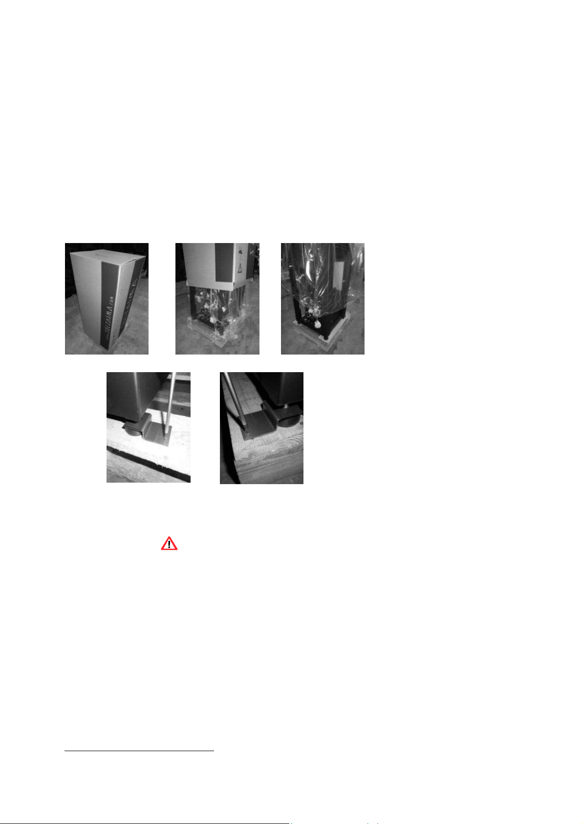
3.1 Unpacking the free-standing fire
When unpacking the stove, please refer to the illustrations below. First remove the retractable bag containing the cardboard box
(Figure 1-a). Then pull the cardboard box out (Figure 1-b) by lifting it and remove the bag containing the free-s t anding
fire stove (Figure 1-c) and the Styrofoam plates. Finally, unscrew the four parts securing the stove to the wood pallet (Figure 1d and -e).
a) b) c)
d) e)
Figure 1 – Unpacking the free-standing fire stove
4 Safety precautions
Waterford Stanley is not liable for any damages to the stove if the specified precautions, warnings and operating procedures are
not followed.
Stoves manufactured by Waterford Stanley are easy to operate and special attention was given to their components in order to
protect users and installers against accidental damages.
The stoves must only be installed by an authorised engineer, who should supply the client with a relevant statement of conformity
and who shall be liable for the final installation and consequent product good operating conditions.
This stove must be used according to its intended use as specified by the manufacturer. The manufacturer is excluded from all
liability, by contract or by tort, caused by injury to people, animals or property arising from misuse or faulty installation or servicing.
After removing the packaging, verify the contents to check their integrity and completeness. If the content of the package
fails to correspond to that indicated in point 1, contact the salesperson from whom you purchased the stove.
All the stove's components guarantee its operation and energy efficiency and should only be replaced with original parts provided
by an authorised technical assistance centre.
The stove must be serviced at least once a year by the installation engineer. This manual is provided with the
product. Please keep it close to the stove.
5
Page 6

4.1 For your safety, we recommend that:
· Make sure you fully read and understand this instruction manual before using the boiler pellet stove as a biomass heating stove.
·
· Make sure that the hydronic/ plumbing circuit was correctly assembled and connected to the water supply before turning on the
boiler pellet stove.
·
· The boiler pellet stove is not intended for use by children or persons with reduced physical, sensory or mental capabilities,
·
· or lack of experience or knowledge, unless they are under supervision or have been instructed concerning the use of the stove.
·
· Do not touch the stove when barefoot or if any part of your body is wet or humid;
·
· Do not tamper with safety or adjustment features without the manufacturer's authorization;
·
· Do not cover or reduce the size of the vents at the installation area;
·
· The boiler pellet stove requires a clear space around the stove for proper combustion, so possible air tightness of the location or
any existing air extraction sources in the room may prevent the stove proper operation;
· The existence of vents is a requisite for proper combustion;
·
· Do not leave the packing materials near children;
·
· During normal operation, Free Standing Fire stove's door must not be opened;
·
· Some parts of the stove may overheat during normal operation, so avoid direct contact with parts such as the door handle and
glass;
·
· Check the existence of any obstructions on the fume duct before turning on the stove after a long period of inactivity;
·
· This boiler pellet stove is intended for residential use in protected areas. Safety systems may turn off the stove. If this occurs,
contact the technical assistance. In any circumstances should you attempt to interfere with the safety systems;
·
· The boiler pellet stove is a biomass heating stove equipped with an electric fume extractor. The occurrence of any power failure
during its use may prevent fume extraction and the room will be filled with smoke. For this reason, you should have a natural
fume extraction system, like a chimney, available;
·
· During operation, NEVER turn off the free-s ta n din g fire stove by disconnecting the electric plug. The fume extractor on
the free-standing pellet fire stove is electric so disconnecting the power plug will prevent the extraction of combustion fumes;
·
· Your stove must be disconnected from the mains for servicing. Before doing this, the stove must be totally cooled down (if
operating before);
·
· Never touch the interior of the stove without disconnecting it from the power mains;
·
· The maximum temperature of the water that can be set by the user (water set-point temperature) is 85°C. In the event of a
temperature of 90ºC being reached, the boiler pellet stove automatically disconnects, and the respective alarm is activated.
6
Page 7

5 Technical specifications
45
50
66
12 12
22 22
Table 1 – Technical specifications
FEATURES
Weight
Height
Width
Depth
Diameter of the fume discharge pipe
Reservoir capacity
Maximum heating capacity
Maximum overall thermal power (fire
Minimum thermal power (fire insert/boiler)
Minimum fuel consumption
Maximum fuel consumption
Rated electrical current
Electric power at start-up (<10 min.)
Rated voltage
Nominal frequency
Thermal yield at rated thermal power
K1700 K2300
202
1150
600
655
100
30
384
14,2 / 3 18,8 / 3,3
4,3 / 0,8 4,3 / 0,8
1,1
3,9
134
434
230
50
91,1
219
1210
665
730
100
520
1,1
5,1
134
434
230
89,2
Stoves
Kg
mm
mm
mm
mm
Kg
m³
kW
kW
Kg/h
Kg/h
W
W
V
Hz
%
Thermal yield at reduced thermal power
Combustion gas flow (max.)
Combustion gas flow (min.)
Max. gas temperature
Min. gas temperature
CO emissions at rated thermal power
CO emissions at reduced thermal power
Draught in the chimney
Stove water volume
Sound level max.
93,8
14,8
6,9
128
66
0,02
0,02
49,1
93,8
%
18,8
6,9
153
0,02
0,024
49,1
g/s
g/s
ºC
ºC
%
%
Pa
W
dB(A)
7
Page 8

Tests performed using wood pellets with a heating capacity of 4.9 kWh/kg.
The above information was obtained during product homologation tests performed at independent laboratories
accredited for pellet stove tests.
Front Rear
Side
Top
Front Rear
Figure 3 – Dimensions of the K2300
Figure 2 – Dimensions of the K1700
Side
Top
Figure 5 – Hydraulic connections of the K1700 Figure 6 – Hydraulic connections of the K2300
8
Page 9

6 Installation of the boiler pellet stove
Before installing, please perform the following steps:
· Upon receipt, check the product for completeness and to determine that is does not show any damage signs. Any damages
or defects should be checked before the stove is installed.
· The stove is equipped with four adjustable height feet at the base which allow for a simple adjustment when installed on a
unlevel surface.
· Remove the instruction manual from the package and hand it over to the client.
· Connect a 100mm diameter flue between the combustion gas output and the outgoing fume extraction duct of the building
(e.g. chimney) – check location diagrams under no. 4.
· If a pipe is used for combustion air inlet from the outside, it shall be no longer than 60cm horizontally or present offsets (such
as bends);
· Perform the hydronic installation
· Connect the 230VAC power cable to a grounded socket.
· The surface of the stove where the hot air outlet is located must be facing the area to be heated.
Figure 7 – Adjustable feet
9
Page 10
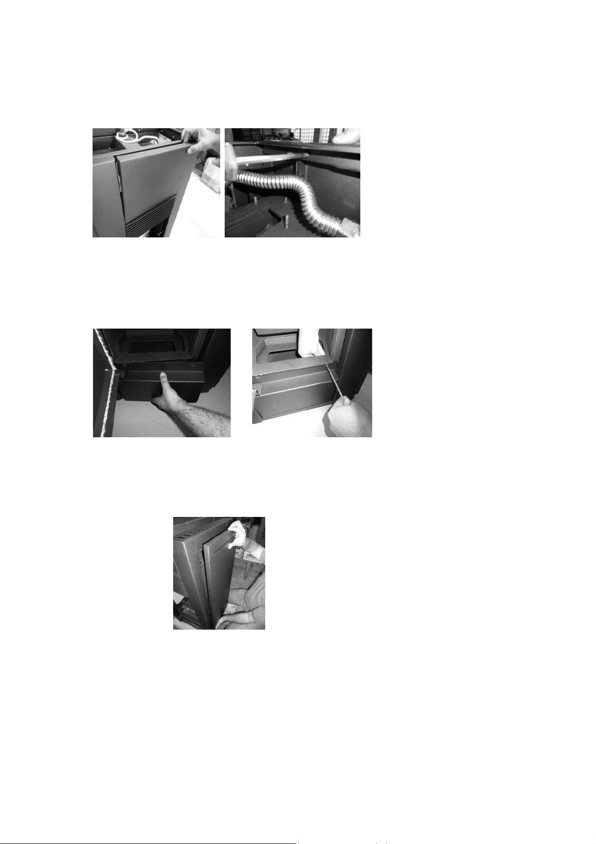
6.1 Assembly of removable parts
After the installation, the stove should be fitted with the removable covers.
- Top front cover
To install the top front cover, place it over the stove (Figure-8a) and then tighten the screws that secure it to the top panel of
the stove (Figure 8b).
8a) 8b)
- Bottom front cover
The bottom front cover can be assembled by removing the screws located on the bottom part of the stove. Then place the part in
the appropriate position (Figure 9-a) and replace and tighten the screws again (Figure 9-b)
Figure 13 – Assembly of the top front cover
9a) 9b)
Figure 14 – Assembly of the bottom front cover
- Side covers
To install the stove's side covers position the covers and insert them as illustrated, onto the existing supports.
Figure 10 – Assembly of side covers
10
Page 11
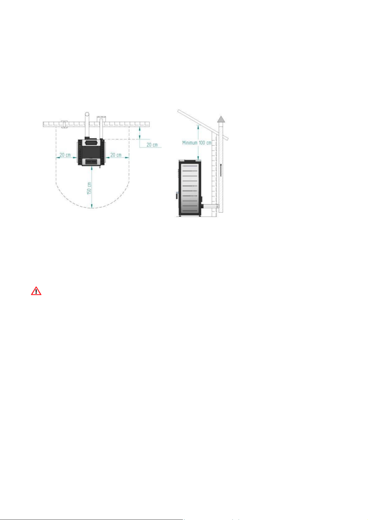
7 Installation requirements
The minimum distance between the free-standing pellet fire stove and particularly flammable surfaces is specified in
Figure 11.
The top of the stove must be at least 100cm separated from the ceiling, especially in rooms with ceilings consisting of
flammable materials.
The base supporting the stove cannot be made of combustible material (e.g. carpet), so make sure you use an adequate
protection.
a) b)
Figure 11 – Clearances to combustibles: a) plan view of the stove's installation;
b) side view of the stove's installation
7.1 Installation of ducts and fume extraction systems:
· The exhaust pipe must have been designed for this purpose, in compliance to the location requirements and in accordance
with any applicable regulations.
· Important! An inspection-T with an airtight lid must be attached to the exhaust pipe of the stove to allow the regular
inspection of the system or discharge of heavy dust and condensates. As indicated in Figure 15, the exhaust pipe must be
assembled to allow cleaning and maintenance of the pipe by inserting inspection points.
· Under normal operating conditions, the combustion gas flow should create a draught of 12 Pa one meter above the chimney
neck.
· The stove must be installed in a shared chimney
· Pipes outside the heated area must be suitably insulated
7.2 Installation without a chimney
The installation of the boiler pellet stove without a chimney should be performed as illustrated in Figure 16, with 100 mm diameter
flue pipe up to the Tee piece for the boiler model) directly outside and over the roof.
Double-walled stainless- s teel insulated pipes must be used and properly fastened to avoid condensation.
A T-tube must be installed at the base of the pipe to allow periodic inspections and annual maintenance, as illustrated in
Figure 16.
11
Page 12

Dia.
125m
Dia.
100mm
Figure 12 – Side view of the installation without a chimney,
Failure to comply with these requirements may prevent the correct operation of the stove. Follow all the instructions
presented on the diagrams.
The pellet stove stoves operate with the combustion chamber in vacuum, so it is necessary to have a fume exhaust pipe to
extract combustion gases properly.
Fume duct material: The tubing must consist of 0.5 mm thick rigid stainless steel, with fastening joints attaching the different
sections and accessories.
Insulation: The fume ducts must be double-walled and insulated to make sure that fumes do not cool down going outwards,
which would cause an inadequate circulation and condensation that may damage the stove.
Windproof terminal: A windproof terminal must always be installed to avoid the backflow of fumes.
Draught in the chimney: The figures below show three standard diagrams, specifying adequate lengths and diameters. Any
other type of installation must guarantee a draught of 12 Pa (0.12mbars) measured when hot and at the maximum power.
Ventilation: The stove must have adequate air for combustion and the room must have adequate air for ventilation , adequate air supply must be
provided in line with building regulations. The boiler pellet stove has a circular pipe (Æ 50mm) that may be connected to the exterior of
the house. An outside air kit and adaptor from 50-100 is available to order from Waterford Stanley.
If the residence has an air exhaust system installed (e.g. kitchen extractor fan), a ventilation duct of suitable cross-
sectional area to accommodate the different exhaust stoves that exist in the house, must be installed.
The installation of the stove on locations near kitchen exhaust fans or fume extractors may prevent the stove from
operating properly.
7.3 Installation with a chimney
If the stove is to be installed in a chimney the stove is installed with a flue pipe of diameter 100 direct to the stove. The chimney
should be lined with a 125mm flexible liner suitable for use with solid fuel. If the chimney is too large, an 125mm mm-wide pipe
should be installed at the fume outlet.
A T-piece must be installed between the 100mm pipe and the 125mm flexi liner t to allow for periodic inspection and annual
maintenance. The installation must be completed with a windproof cowl recommended for use with pellet stoves.
We do not recommend that you use the stove in rough weather conditions that may seriously impact the draught (particularly
with very strong winds).
If you do not use the stove for a long time, check it to make sure that the flue pipes are clear before lighting the fire.
12
Page 13

7.4 Hydronic Installation
* The chapter 14 (installation diagrams) contains the optional connection diagrams for central heating installations, with or
without water heating for household use;
* The boiler model pellet stove is equipped with a circulating pump, an expansion vessel (6 litre volume (in the K1700model)
or 10 litre volume (in the K2300 model) and a 3-bar safety valve;
* Operating pressure is between 1 and 1.5 bars;
* To empty the stove, attach a "T-tube" with a tap to the waste water drain the safety valve (3 bar) outlet must also be connected to
the waste water drain;
*The heating fluid must consist of water with an anti-rust, non-toxic product added in the quantity recommended by the
manufacturer. If the stove installation or the fluid pipes are installed are likely to freeze, the installation engineer must add to the
circulating fluid the amount of antifreeze product recommended by the manufacturer, to avoid freezing at the estimated minimum
temperature.
8 Fuel
The boiler pellet stove must be operated exclusively with pellets. No other fuel may be used.
Use only pellets certified by standard EN 14961-2 grade A1, with a
6 mm diameter and measuring between 10 and 30 mm long.
The pellets must not have a moisture content in excess of 8% . To guarantee a good combustion, the pellets must maintain
these characteristics so they should be stored in a dry place.
The use of different pellets will reduce the efficiency of the stove and cause poor combustion.
You should always use certified pellets and must test a sample before buying large bulk loads.
The physical/chemical properties of the pellets (i.e. the calibre, friction, density and chemical composition) may vary within
specific tolerances and according to each manufacturer. Please note that this may cause alterations to the feeding process
and, consequently, the need for different doses (more or less pellets).
The stove allows the dose of pellets to be adjusted during start-up and at power levels by ± 25%
Warning : The stove must NOT be used as an incinerator
13
Page 14

9 Use of the Boiler pellet stove
Recommendations
Before starting up the stove, please check the following:
· Guarantee that the stove is properly connected to the power mains using the 230VAC power cable.
Figure 13 – Electric power plug.
· Check to see whether the pellet reservoir is supplied with pellets. Inside the pellet reservoir is a safety grid to prevent
users from reaching the worm screw.
· Ensure that before each lighting the burner is clear
The stove's combustion chamber is made from iron plate and painted with high temperature-resistant paint, releasing
fumes during the first burning sessions due to paint curing.
Make sure that the hydraulic circuit was correctly assembled and is filled to the correct pressure.
You should check that there is sufficient ventilation in the room where the stove is installed, otherwise it will not work properly. You
should therefore check to see whether there are other heating air-consuming stoves in the room (e.g. gas stoves, fire pits,
extractors, etc.); these should not be used simultaneously with the stove.
The Boiler pellet stove stoves have a probe for measuring the room temperature. This probe is attached to the grid on the rear
panel (Figure 20). For a good reading of the room temperature, avoid the contact between the end of the probe and the
stove chassis. You may also attach the probe to the wall beside the stove.
Figure 14 - Room temperature probe
14
Page 15

20.5ºC
16:03
OFF
MODE
MENU
MAN
ESC
OK
ON
OFF
- +
9.1 Remote control and display
AUT
Figure15 – Remote control and display
a) b) c)
a) Key to toggle between manual and automatic mode and exit menus (esc).
b) Key to access menus and confirmation key (ok).
c) Key to start/stop the stove and reset error messages.
d) e)
d) Key to scroll the menus to the left, or to reduce the set point
e) Key to scroll menus to the right or increase the set p oint
15
Page 16

MODE MENU
MAN
OK
OFF
-
+
MODE MENU
MAN
OK
OFF
-
+
esc
Set
< Data e
Hora
>
MODE MENU
MAN
AUT ESC
OK
ON
OFF
-+
9.2 Display information summary
9.2.1 Menu
Menu indicating that the stove power is "off", the room temperature in ºC and Time.
20.5ºC 16:03
OFF
Selecting the operation mode: to select the operation mode, press the “mode” key to
select “Manu” for manual mode or “Auto”
Note: For boiler models manual mode is unavailable.
Mode:AUTO Menu
Temp:30ºC Fan:5
“Auto” mode: in this mode, the stove shall be turned on at maximum power until reaching a temperature of 1ºC above the
temperature selected (set point temperature). Upon reaching the set temperature, the stove changes to minimum operating
power.
The set-point temperature can be set between 5 and 35ºC by pressing the "-" key.
The "+" key allows the user to set the ventilation speed between 1-5 and automatic mode.
9.2.2 Water temperature
Press the Menu key twice to set the water temperature;
“Water Temp.” appears on the display. Press Set to adjust the set point.
· Heating temperature
To set the desired heating temperature press “set”. The display starts to flash. Press the “+” or “-“ key to select the desired
temperature and then “ok” to confirm.
9.2.3 Date/Time
To set the date and time: press the Menu key twice followed by the “+” . “Day and Time” appears on the display. Press "set" to
see the “Time” menu.
"
16
Page 17

· Year
To set the year press “set”. The display starts to flash. Press the “+” or “-” key to select the desired year and then “ok” to confirm.
Press "esc" to return to the " Date and Time " menu then "+" month menu. The Timer menu appears.
•
· Month
To set the month press “set”. The display starts to flash. Press the “+” or “-” key to select the desired month and then “ok” to
confirm. Press the "+" key to go to the " date " menu.
· Day of the month/ Date
To set the date press “set”. The display starts to flash. Press the “+” or “-” key to select the desired day and then “ok” to
confirm. Press the "+" key to go to the " day of the week " menu.
· Day
To set the day of the week press “set”. The display starts to flash. Press the “+” or “-” key to select the desired day and then
“ok” to confirm. Press the "+" key to go to the "Time." (Day Number) menu.
· Time
To set the time press “set”. The display starts to flash. Press the “+” or “-” key to select the desired time and then “ok” to
confirm. Press the "+" key to go to the "Minutes
· Minutes
To set the minutes press “set”. The display starts to flash. Press the “+” or “-” key to select the desired minutes and then
“ok” to confirm.
17
Page 18

9.2.4 Timer
The stove is equipped with a timer that allows the stove to be turned on or off at a specified time.
Setting the timer/s
Step 1 Press the “set” button twice followed by the “+” button to display “ chrono”
Step 2 Press the “set” button to display “ enable”.
Step 3 Press the “+” button to scroll right, “load profile” is displayed.
Step 4 Press the “+” button to scroll right, “reset” is displayed.
Step 5 Press the “+” button to scroll right, “program 1” is displayed.
Step 6 Press the “set” button , “enable” is displayed.
Step 7 Press the “+” button to scroll right, “start” is displayed, Press the “set” button.
Step 8 Use “+” and “-“ to adjust the “start” time. Followed by “ ok to confirm.
Step 9 Press the “+” button to scroll right, “stop” is displayed, Press the “set” button.
Step 10 Use “+” and “-“ to adjust the “stop” time. Followed by “ ok ” to confirm.
Step 11 Press the “+” button to scroll right, “air temperature” is displayed, Press the “set” button.
Step 12 Use “+” and “-“ to adjust the “air temperature” . Followed by “ ok ” to confirm.
Step 13 Press the “+” button to scroll right, “air temperature” is displayed, Press the “set” button.
Step 14 Use “+” and “-“ to adjust the “air temperature” . Followed by “ ok ” to confirm.
Step 15 Press the “+” button to scroll right, “water temperature” is displayed, Press the “set” button.
Step 16 Use “+” and “-“ to adjust the “water temperature” . Followed by “ ok ” to confirm.
Step 17 Press the “+” button to scroll right, “fire” is displayed, Press the “set” button.
Step 18 Use “+” and “-“ to adjust the “fire” . Followed by “ ok ” to confirm.
Step 17 Press the “+” button to scroll right, “Days” is displayed, Press the “set” button.
Step 18 Use “+” and “-“ and “ set “ buttons to select the days which the program will run on.
Step 19. Return to steps 6 and steps 2 and set both of these to “On” to enable Program 1.
Repeat for Programs 2-6 as required.
Note,
It is not possible to enable the timer until the programs are set.
Step 6 is to enable program 1.
Step 2 is to enable the timer function.
18
Page 19

9.2.5 Sleep
MODE MENU
MAN
OK
OFF
-
+
MODE MENU
MAN
AUT ESC
OK
ON
OFF
-+
The "Sleep" menu allows you to setup the time you want the stove to turn off.
esc OFF Set
SLEEP
Press "set". The display starts to flash. Select the desired time using the "-" and "+" keys. After choosing the time, press "ok" to
confirm. Press "esc" to return to the menu and "+" to go to the configuration menu.
esc 22:00 Set
SLEEP
9.3 Configuration menu
To change the configurations of the boiler pellet stove, press “set”.
The "Língua" (Language) menu appears allowing you to select the language.
· Language
To select the language, press “set”. Using the “+” or “-” keys, select the desired language (Pt – Portuguese; Nl – Dutch; Gr –
Greek; It – Italian; En – English; Fr – French; Es – Spanish; De – German). Press "ok" to confirm.
Press the "+" key to go to the "eco" menu.
· Eco mode
If the stove is equipped with a thermostat that operates exclusively based on the temperature, the "eco mode" can be enabled
to reduce the fuel consumption. In this mode, the stove operates at a set point temperature. The stove always runs at
maximum operating power until it reaches a temperature (1ºC) above the set point temperature. Upon reaching this
temperature, the stove starts operating at minimum operating power for a preset time period. After this time has elapsed, the stove
turns off. It remains off for another preset period of time. When the measured room temperature drops to a preset value, the
stove turns on again at the maximum operating power.
This operation is only available in automatic mode.
To activate the eco mode, press "set". The display starts to flash. Select "On" or "Off" using the "-" and "+" keys. Press "set" to
confirm the selection.
Press "esc" to return to the previous menu and "+" to go to the (Lighting) menu.
19
Page 20

esc Off Set
MODE MENU
MAN
OK
OFF
-
+
esc
Auto Set ºC / ºF >
MODE MENU
MAN
OK
OFF
-
+
< Eco >
· Lighting
To select lit screen, press “set”. The display starts to flash. Press the "+" or "-" key to select the time at which you want the
screen to light up, or choose "On" to keep the light on at all times. Press "ok" to confirm. Press the "+" key to go to the (Tones)
menu.
· Tones
To activate the key tone, press "set". The display starts to flash. Press the "+" or "-" key to select "On" or "Off". Press "ok" to
confirm. Press the "+" key to go to the "ºC/ºF" menu.
· Temperature stove (ºC/ºF)
To select ºC / ºF, press “set”. The display starts to flash. Press the “+” or “-” key to select “ºC”, “ºF” or “Auto”, and then “ok” to
confirm. Press the "+" key to go to the " Pellet" (Pellet Qty) menu.
<
· Pellet quantity
Press "set" to see the "(Temporary settings) menu.
- Temporary settings
This feature allows you to increase or decrease by 25% the quantity of pellets at start- up. Press "set". The display starts to
flash. Press "+" or "-" to increase or decrease (between -5 to +5), accordingly. Each stove must be multiplied by 5 to obtain
the correct percentage. Press "ok" to confirm. Press the "+" key to go to the " (Power settings) menu.
20
Page 21

- Power settings
This feature allows you to increase or decrease by 25% the quantity of pellets at each power level. Press "set". The display
starts to flash. Press "+" or "-" to increase or reduce (from -5 to +5), accordingly. Each stove must be multiplied by 5 to obtain
the correct percentage. Press "ok" to confirm. Press "esc" to return to the (Pellet Qty) menu and "+" to go to the (Thermostat)
menu.
· Thermostat
This feature allows you to enable or disable the room temperature thermostat. Press “set”. The display starts to flash. Press
the “+” or “-” key to select "On" or "Off" and then “ok” to confirm. Press the "+" key to go to the (Pellet loading) menu.
· Pellet loading
This feature allows you to enable the worm drive to fill the channel when it is empty to keep the stove running. Press "set";
the "ok" option appears. Press "ok" to activate the drive (the " (Activated) message appears) and "esc" to stop it. Press the
"+" key to go to the (Cleaning) menu.
· Cleaning
This feature allows you to clean the burning basket manually. Press "set"; the "ok" message appears. Press "ok" to start
the cleaning; the " (Activated) message appears. When you wish to stop, press "ok". Press the "+" key to go to the (Technical)
menu.
The technical menu is not available to the end user since it includes exclusively factory settings that must never be changed.
21
Page 22

9.4 User Info
esc Set < Info Usuario
>
MODE MENU
MAN
OK OFF
-
+
This menu contains some user information regarding the Free-Standing Fire stove. Press "set"; the " (File Code) menu appears.
Display software/firmware code Press the "+" key to go to the (Operating Hours) menu.
This menu shows for how many hours the stove has been operating.
Fume extractor operating speed (rotation per minute).
Airflow measured by the air probe.
Fume temperature.
Worm drive rotation time ("On").
22
Page 23

Ventilation power level.
Hydraulic circuit pressure
10 Start-up
To start operating the Boiler pellet stove, press the start/stop button for 3sec. The display should indicate " Lighting " until the
completion of this phase.
The pellets will pass through the supply channel to the burning basket (combustion chamber), where they will be ignited
using a heat resistor. This process may take between 5 and 10 minutes, depending on whether the worm screw used to push
through the pellets has been previously filled with fuel or is empty. Upon completion of the ignition phase, the word "On"
should appear on the display. The heating power can be adjusted at any time by pressing the power selection button for
approximately 1 second.
Users can choose between five preset power levels. The selected power is indicated on the display. The initial power at each start-
up will be correspond to the power level set before the last stop.
10.1 Stop
The stop sequence of the stove is started by pressing the start/stop key for 3sec.
Until this phase has been completed, the display will show (Disabling). The extractor will remain active until the fume temperature
of 104ºF (40ºC) is reached, to guarantee that all the material has been burnt.
10.2 Turning off the stove
The stove should only be disconnected after stoppage.
Make sure that the display indicates “Off”. If necessary, disconnect the power cable from the mains.
10.3 Instructions for removing the side covers
10.3.1 Remove side covers
Raise the cover and pull backwards removing the upper and lower fixtures. Do the opposite to assemble the stove.
23
Page 24

Figure 16 – Removal of side covers
10.3.2 Pellet reservoir lid
The pellet reservoir is opened by sliding the bolt sideways Figure 17a
The lift the lid using the Tab Figure 17b
a) b)
Figure 17
10.4 Filling the pellet reservoir
1 – Open the pellet reservoir lid at the top of the stove, as shown in Figure 18.
2 – Pour the pellets into the reservoir, as shown in Figure 18.
.
Figure 18 – Refilling the pellet reservoir
3 - Turn on the stove and close the lid, pressing it down as shown in Figure 17-a.
24
Page 25

11 Maintenance
The Waterford Stanley boiler model pellet stove requires careful maintenance. The most important thing is to remove the ash from
the pellet burning area at regular intervals. This can be easily done by using a simple household vacuum cleaner. It should be
cleaned after burning approximately
60kg of pellets.
Note: However, before cleaning, the power of the stove must be turned off and the stove should be cold enough to prevent
accidents from occurring.
11.1 Cleaning the stove
To perform maintenance on the boiler model pellet stove, clean the airflow pipes. To do this, raise the lid on the top of the
stove (Figure 18-a) and then turn (Figure 18-b) and lift the levers inside several times (Figure 18-c) to make the dirt accumulated
inside the pipes fall out.
Figure 39 – Cleaning the turbulators
a) b)
c)
25
Page 26

Then clean the inside of the stove using a steel brush on the surfaces where dirt has accumulated (Figure 19).
a) b)
Figure 19 – Cleaning the interior of the boiler model
The burning basket (Figure 20-a) and ash basket
(Figure 20-b) must then be removed and the ash vacuumed from both. The interior of the stove must also be cleaned by opening
the hatch, as shown in Figure 21. Finally, assemble the parts in the reverse to which they were removed and close the stove door.
a) b)
Figure 41 – a) Burning basket; b) Ash basket
Figure 7 – Cleaning the burning basket
a) b)
Figure 21 – Cleaning the interior of the stove
26
Page 27

11.2 Additional cleaning
For every 1300-1700lbs (600-800kg) of pellets consumed, additional cleaning should be performed.
For the boiler stove, the procedure involves cleaning the air flow pipes and turbulators. To do this, open the lid on the top of
the stove (Figure 22-a) and remove the six wing nuts securing each turbulator set (Figure 22-b and 22-c). Then pull the turbulators
up (Figure 22- d/e). A vacuum cleaner must be used to clean this area (Figure 51-f) and the interior of the pipes (Figure 22-g) can
be cleaned with a steel brush. The turbulators that are removed must also be cleaned with a steel brush (Figure 22-h).
To reinstall the turbulators, execute in reverse the above procedure shown in the figures.
a) b)
c) d)
e) f)
g) h)
27
Page 28

Figure 23 – Cleaning the air flow pipes and turbulators
If fumes are not being extracted in the best manner possible, we recommend you clean heat exchanger and the extractor as
shown in Figures 22 and 23. However, we recommend that you perform this procedure at least once a year.
a) b)
Figure 23 – Vacuum the air flow pipes
Figure 23 – a) Remove the screws; b) Remove the extractor
11.3 Cleaning the glass
The glass may only be cleaned with the stove completely cold, and using an appropriate product, as per the instructions for
use. You should prevent the product from reaching the sealing ring and painted metal parts so that no undesirable oxidation
occurs. The sealing ring is glued, so should not be exposed to moisture from water or cleaning products.
a) b)
Figure 25 – Cleaning of the glass: a) moisten a soft cloth with liquid; b) clean the glass with the cloth
Figure 24 – Incorrect cleaning of the glass
Important note (only for the air model): The back of the deflector plate should be cleaned once a year.
28
Page 29

12 Alarms / failures / recommendation list
Alarm
Code
Troubleshooting
-
-
-
-
-
-
-
-
-
-
-
-
-
-
-
-
-
-
-
-
-
Failures
Maintenance
range
12.1 Alarms
Ignition failure
No flame or lack of pellets
Excess heat in the pellet
drum
Excess fume temperature
Pressure switch alarm
Air mass probe
The door is open
Fume extractor is faulty
Fume probe failure
Pellet resistance error
Worm drive error
Pellet level alarm
Water pressure outside
operating range
Excess water temperature
A01
A02
A03
A04
A05
A06
A07
A08
A09
A10
A11
A15
A16
A18
Maximum time 2400
Temperature under:
- 104ºF (40°C) (air
model)
- 109.4ºF (43°C)
(boiler model)
Over 446ºF (230°C)
Over 446ºF (260°C)
(boiler model)
The door is open, lack
of draught or extractor
40 Ipm delta for 3600
Door open for 60
Connection failure
Connection failure
Connection failure
Connection failure
sec
194ºF (90°C)
(air model);
fault for 60 sec
sec
seconds
the worm drive channel is empty - restart the
stove
resistance burnt – replace resistance
the burning basket has been incorrectly
installed
Pellet reservoir is empty
the fan is not working – call for assistance
faulty thermostat - call for assistance
machine with faulty ventilation
the fan is not working or is working at a low
power level - increase the level to the
maximum (if the problem persists, call for
assistance)
Insufficient extraction
Excess pellets
close the door and clear the error message
on the faulty pressure regulator
obstruction of the exhaust pipe or faulty
extractor
pipes with insufficient extraction or obstructed
pipes
close the door - clear the error message
check connection
check connection
check connection
check connection
check connection
check connection
check connection
Table 2 – List of alarms
Important note: all alarms cause the machine to shut down. The alarm must be reset and restarted. To reset the
stove press the “On/Off” button for 10 seconds until the alarm sounds.
12.2 - Failures
Table 3 – List of failures
Important note: the failures do not case the machine to shut down
In case of an emergency, shut the stove down following the normal procedure to switch the stove off.
Warning!
THE STOVE WILL BE HOT DURING OPERATION SO CARE MUST BE TAKEN ESPECIALLY WITH THE DOOR GLASS
AND HANDLE.
Air probe failure
Low pellet level
The door is open
Air temperature probe failure
Water temperature probe failure
Water pressure sensor fault
Water pressure close to being outside operating
.
Warning!
29
Page 30

13 Exploded view.
30
Page 31

14 Installation diagrams
14.1 Central heating installation diagram
Figure 26 – Central heating installation diagram.
14.2 Installation diagram for central heating and DHW using a cylinder thermostat
Figure 27 – Installation diagram for central heating and household water heating using a cylinder thermostat
31
Page 32

14.3 Symbols
Figure 28 – Symbols
14.4 Electrical diagram of the Boiler pellet stove.
Figure 29 – Electrical diagram
32
Page 33

14.5 Remote switched connection.
The volt free connection on the rear of the stove can be used to provide a remote call for heat.
The product can be set up with a remote timeclock, room thermostats and motorised valves using the
standard S plan configuration where the auxiliary switch wires of the motorised valve can be connected to
the remote connections in place of the wires in the picture below providing a call for heat.
All electrical connections must be made by a competent electrician.
Note,
Connections are low voltage; a closed loop will call the stove. Remote connections should be designed to
switch infrequently to avoid excessive start up and shut down of the boiler.
Figure 30 – Remote connection
15 Performance graphs for the UPSO 15-55 CIAO circulating pump
Figure 31 – Performance graphs for the circulating pump
16 Life cycle of a Boiler pellet stove
Around 90% of the materials used in the manufacture of these stoves are recyclable, thus helping to reduce environmental impact
and contributing to the sustainable development of the Planet. End-of-life stoves should be returned to authorised waste
processing systems. We advise you to contact your local authorities for instructions.
33
Page 34

17 Annexes
Operations flow charts
· Flow chart 1 – Normal operation.
Note (only for the boiler model): The circulating pump operates intermittently from the moment the water temperature reaches
50ºC and operates continuously from the set-point temperature.
34
Page 35

· Flow chart 2 – Switching off the pellet stove.
Note The circulating pump is turned off when the water temperature reaches below
40ºC.
35
Page 36

Supplied by
Waterford Stanley Ltd.,
Stove 401-403, IDA Industrial Estate,
Cork Road,
Waterford, Ireland.
Tel: (051) 302300
www.waterfordstanley.com
36
 Loading...