

Page 1

1-855-365-2407
Page 2
EXIT DEVICE
WIRING T
EMPLATE
K2 QED100/300 SERIES WITH :
LR (ELECTRIFIED LATCH RETRACTION)
ED (ELECTRIFIED DOGGING)
NOTES:
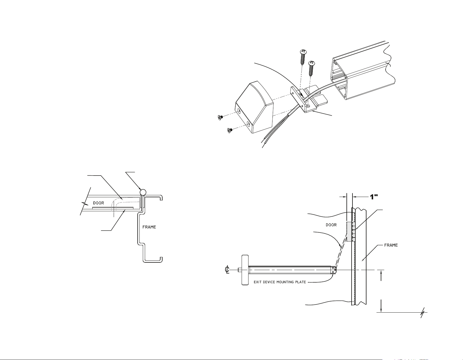
Route wires as shown
and terminate at the
power transfer device.
1.) Use QED100/300 series template for door
preparation. provide additional prep, as
shown, for electric lock modifications.
2.) Left hand reverse shown; opposite for
right hand reverse models.
3/8” Raceway
Reinforcement plate
recommended for
device mounting.
Power transfer
Mounting tab – see QED100/300 series
template for proper installation.
device
Power transfer
device
Door fabricator to provide a 3/8”
diameter (minimum) raceway through
door to allow the insertion of electrical
wires running between the exit device
and the power transfer device.
2 / 3
40” to
finished floor
Page 3

Request-to-exit Switch Installation Instructions
K2 QED100/300 SERIES WITH REQUEST-TO-EXIT (X) SWITCH
SWITCH MONITORS EGRESS BY PUSHBAR ACTIVATION OF EXIT DEVICE.
FIELD INSTALLATION INSTRUCTIONS
1. Remove chassis cover from device.
2. Separate pushbar and latch assembly from mechanism housing.
3. Place assembly into device as shown. Assembly fits over the top if the existing holes.
4. Ensure the switch arm is placed on the outside of the center link on the pushbar so that the switch is
preactivated.
5. Used provided round head screws and lock washers to secure switch assembly to pushbar baseplate.
6. Check for proper switch activation. When pushbar is fully depressed, switch should activate.
7. Run the wires along the outside edge of the pushbar mechanism.
8. Re-assemble the mechanism housing onto the pushbar mechanism.
9. Secure the self-adhesive wire tie mount holder to the bottom of the mechanism housing in the end of
the devise (as shown.)
switch
3 / 3
1.) Use QED100/300 series template for door
preparation. Instructions provided, as
shown, for switch kit modification.
5026917-03
Copyright © 20
Stanley Black & Decker
 Loading...