

Page 1
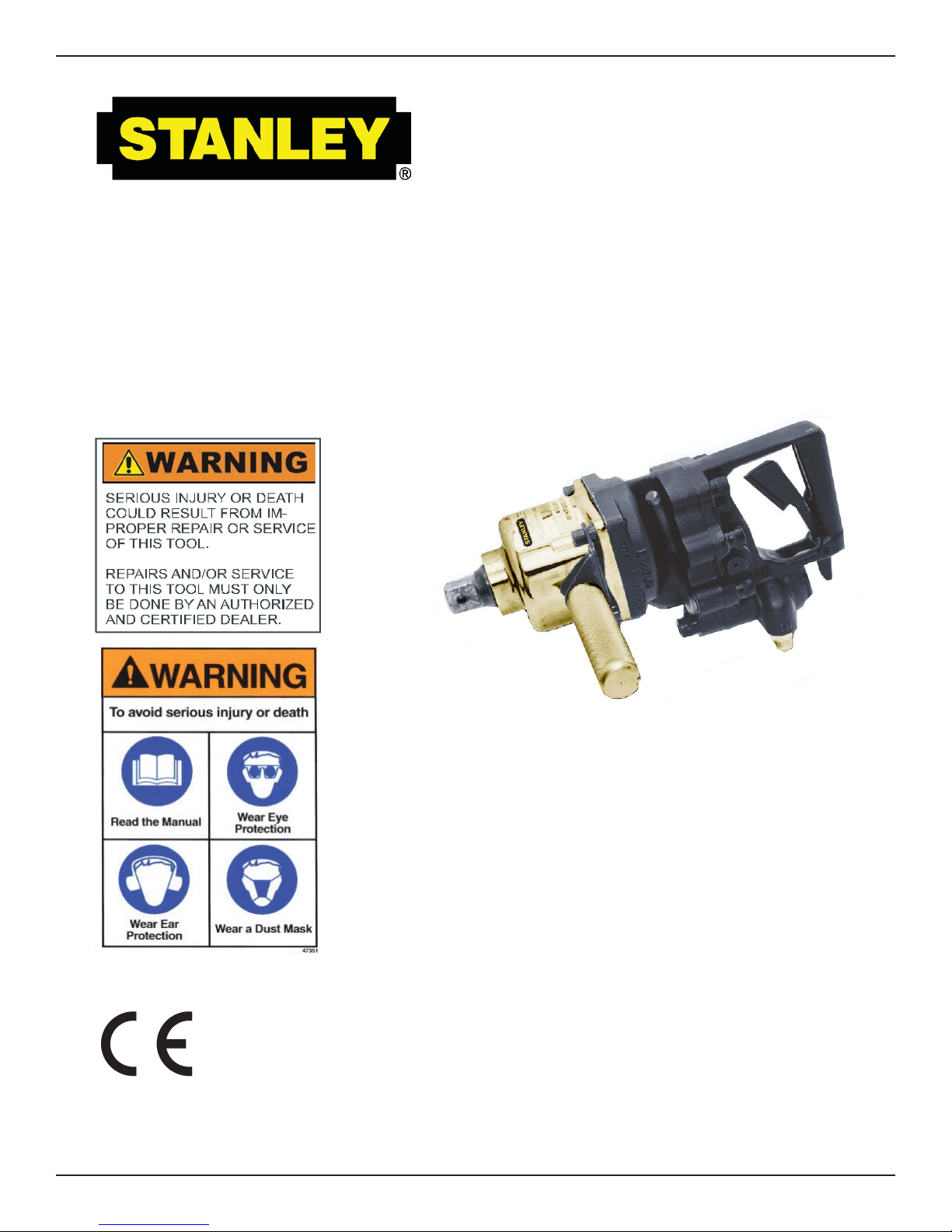
IW16
HYDRAULIC
IMPACT WRENCH
Copyright© The Stanley Works 2005
OPS/MAINT. USA
Printed in U.S.A.
66174 3/2009 ver 3
SAFETY, OPERATION AND MAINTENANCE
USER'S MANUAL
Stanley Hydraulic Tools
3810 SE Naef Road
Milwaukie OR 97267-5698
503-659-5660
FAX 503-652-1780
www.stanleyhydraulic.com
Page 2

Page 3
TABLE OF CONTENTS
CERTIFICATE OF CONFORMITY......................................................................................................................................4
SAFETY SYMBOLS ............................................................................................................................................................ 5
SAFETY PRECAUTIONS ...................................................................................................................................................6
TOOL STICKERS & TAGS .................................................................................................................................................7
HYDRAULIC HOSE REQUIREMENTS ..............................................................................................................................8
HTMA REQUIREMENTS ....................................................................................................................................................9
OPERATION .....................................................................................................................................................................10
WRENCH TORQUE INFORMA TION ........................................................................................................................... 10
FACT ORS THAT AFFECT TORQUE ........................................................................................................................... 10
BOLT GRADE AND THREAD RECOMMENDATIONS ................................................................................................10
PREOPERATION PROCEDURES ..............................................................................................................................10
CHECK POWER SOURCE .........................................................................................................................................10
CONNECT HOSES ......................................................................................................................................................10
WRENCH OPERATION ...............................................................................................................................................10
COLD WEATHER OPERATION ...................................................................................................................................11
POST OPERATION UNDERWATER MODELS ONLY .................................................................................................11
EQUIPMENT PROTECTION & CARE .............................................................................................................................. 12
TROUBLESHOOTING ......................................................................................................................................................13
SPECIFICA TIONS ............................................................................................................................................................ 14
ACCESSORIES ................................................................................................................................................................14
IW16 PARTS ILLUSTRATION ..........................................................................................................................................15
IW16 EXT. HANDLE ILLUSTRATION ............................................................................................................................... 16
IW16 PARTS LIST ............................................................................................................................................................17
WARRANTY......................................................................................................................................................................18
SERVICING THE STANLEY HYDRAULIC IMPACT WRENCH: This manual contains safety, operation, and
routine maintenance instructions. Servicing of hydraulic tools, other than routine maintenance, must be
performed by an authorized and certifi ed dealer. Please read the following warning.
SERIOUS INJURY OR DEATH COULD RESULT FROM THE IMPROPER REPAIR OR SERVICE OF THIS TOOL.
REPAIRS AND / OR SERVICE TO THIS TOOL MUST ONLY BE
DONE BY AN AUTHORIZED AND CERTIFIED DEALER.
For the nearest authorized and certifi ed dealer, call Stanley Hydraulic Tools at the number listed on the
back of this manual and ask for a Customer Service Representative.
WARNING
3
Page 4
CERTIFICATE OF CONFORMITY
ÜBEREINSTIMMUNGS-ZERTIFIKAT
CERTIFICAT DE CONFORMITE CEE
CERTIFICADO DE CONFORMIDAD
CERTIFICATO DI CONFORMITA
Hydraulic Tools
______________________________________________________________________
I, the undersigned:
Ich, der Unterzeichnende:
Je soussigné:
El abajo firmante:
lo sottoscritto:
hereby certify that the construction plant or equipment specified hereunder:
bestätige hiermit, daß das im folgenden genannten Werk oder Gerät:
certifies par ceci que l’ usine ou l’ équipement de constructio n indiqué cidessous:
por el presente certifico que la fabrica o el equipo especificado a continuacion:
certifico che l’impianto o l’attrezzatura sotto specificata:
1. Category: Impact Wrench
Kategorie:
Catégorie:
Categoria:
Categoria:
2. Make/Ausführung/Marque/Marca/Marca
3. Type/Typ/Type/Tipo/Tipo: IW1615001, IW1635001, IW1615701
4. Serial number of equipment:
Seriennummer des Geräts:
Numéro de série de l’équipement:
Numero de serie del equipo:
Matricola dell´attrezzatura:
5. Year of manufacture/Baujahr/année de fabrication/Año de fabricacion/Anno di fabbricazione beginning 2005
Has been manufactured in conformity with - EEC Type examina tion as shown.
Wurde hergestellt in Übereinstimmung mit - EEC Typ-Prüfung nach.
Est fabriqué conformément - au(x) type(s) examiné(s) comme indiqué dans le tableau ci-après.
Ha sido fabricado de acuerdo con - tipo examen EEC como dice.
E’ stata costruita in conformitá con - le norme CEE come illustrato.
Burrows, James
Surname and First names/Familiennname und Vornamen/Nom et prénom/Nombre y apellido/Cognome e nome
Stanley
All
Examen CEE de type
Directive
Richtlinie
Directives particulières
Directriz
Direttiva
EN
EN ISO
ISO
EN Machinery Directive
6. Special Provisions: None
Spezielle Bestimmungen:
Dispositions particulières:
Provisiones especiales:
Disposizioni speciali:
7. Representative in the Union: Stanley Dubuis 17-19, rue Jules Berthonneau-BP 3406 41034 Blois Cedex, France.
Done at/Ort/Fait à/Dado en/Fatto a Stanley Hydraulic Tools, Milwaukie, Oregon USA
Signature/Unterschrift/Signature/Firma/Firma____________________________________________________________________________
Position/Position/Fonction/Puesto/Posizione Engineering Manager
No.
Nr
Numéro
No
n.
792-6
3744
8662-7
98/37/EC
Date
Datum
Date
Fecha
Data
1994
1995
1997
1998
5/17/05
Approved body
Prüfung durch
Organisme agréé
Aprobado
Collaudato
Self
Self
Self
Self
Date/Datum/le/Fecha/Data 5/17/05
Date of expiry
Ablaufdatum
Date d´expiration
Fecha de caducidad
Data di scadenza
NA
NA
NA
NA
4
Page 5
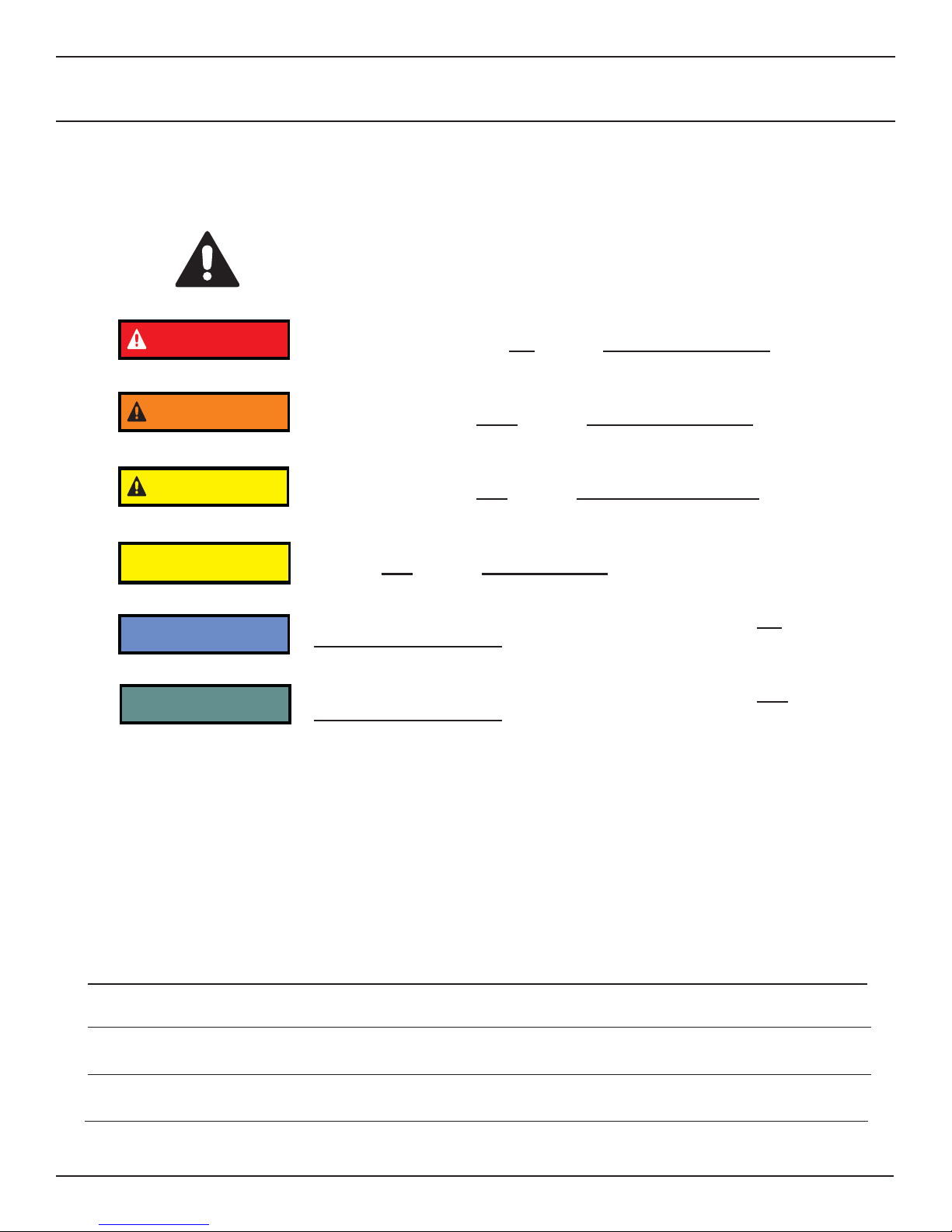
SAFETY SYMBOLS
Safety symbols and signal words, as shown below, are used to emphasize all operator, maintenance and repair
actions which, if not strictly followed, could result in a life-threatening situation, bodily injury or damage to equipment.
This is the safety alert symbol. It is used to alert you to potential personal
injury hazards. Obey all safety messages that follow this symbol to avoid
possible injury or death.
This safety alert and signal word indicate an imminently hazardous situa-
DANGER
WARNING
CAUTION
CAUTION
tion which, if not avoided, will result in death or serious injury.
This safety alert and signal word indicate a potentially hazardous situation
which, if not avoided, could result in death or serious injury.
This safety alert and signal word indicate a potentially hazardous situation
which, if not avoided, may result in minor or moderate injury.
This signal word indicates a potentially hazardous situation which, if not
avoided, may result in property damage.
This signal word indicates a situation which, if not avoided, will result in
NOTICE
IMPORTANT
Always observe safety symbols. They are included for your safety and for the protection of the tool.
damage to the equipment.
This signal word indicates a situation which, if not avoided, may result in
damage to the equipment.
LOCAL SAFETY REGULATIONS
Enter any local safety regulations here. Keep these instructions in an area accessible to the operator and maintenance personnel.
5
Page 6
SAFETY PRECAUTIONS
Tool operators and maintenance personnel must always comply with the safety precautions given in this manual and on the stickers and tags attached to the tool and
hose.
These safety precautions are given for your safety. Review them carefully before
operating the tool and before performing general maintenance or repairs.
Supervising personnel should develop additional precautions relating to the specifi c
work area and local safety regulations. If so, place the added precautions in the
space provided on page 5.
The model IW16 Hydraulic Impact Wrench will provide safe and dependable service
if operated in accordance with the instructions given in this manual. Read and understand this manual and any stickers and tags attached to the tool and hose before
operation. Failure to do so could result in personal injury or equipment
damage.
• The operator must start in a work area without bystanders. Flying debris can cause serious injury.
• Do not operate the tool unless thoroughly trained or under the supervision of an instructor. Establish a training program
for all operators to ensure safe operation.
• Always wear safety equipment such as goggles, ear and head protection, and safety shoes at all times when operating
the tool. Use gloves and aprons when necessary.
• Inspect tool daily for loose fasteners, missing parts and leakage. Have tool repaired if necessary.
• The operator must be familiar with all prohibited work areas such as excessive slopes and dangerous terrain conditions.
• Maintain proper footing and balance at all times.
• Do not inspect or clean the tool while the hydraulic power source is connected. Accidental engagement of the tool can
cause serious injury.
• Always connect hoses to the tool hose couplers before energizing the hydraulic power source. Be sure all hose connections are tight and are in good condition.
• Do not operate the tool at oil temperatures above 140°F/60°C. Operation at higher temperatures can cause higher than
normal temperatures at the tool which can result in operator discomfort.
• Do not operate a damaged, improperly adjusted, or incompletely assembled impact wrench.
• Never wear loose clothing that can get entangled in the working parts of the tool.
• Keep all parts of your body away from the rotating parts. Long hair or loose clothing can become drawn into rotating
components.
• Always use accessories that conform to the specifi cations given in the OPERATION section of this manual.
• Do not reverse impact wrench rotation direction by changing fl uid fl ow direction.
• Release the trigger if the power supply has been interrupted.
• When working near electrical conductors, always assume that all conductors are energized and that insulation, clothing
and hoses can conduct electricity. Use hose labeled and certifi ed as non-conductive.
• To avoid personal injury or equipment damage, all tool repair, maintenance and service must only be performed by authorized and properly trained personnel.
6
Page 7

TOOL STICKERS & TAGS
D
Failure to use hydraulic hose labeled and certified
as non-conductive when using hydraulic tools on
or near electric lines may result in death or
For proper and safe operation read owners manual
and mwke sure that you have been properly
trained in correct procedures required for work
serious injury.
on or around electric lines.
ELECTROCUTION
HAZARD
DANGER
Failure to use hydraulic hose labeled and certified
as non-conductive when using hydraulic tools on
or near electric lines may result in death or
serious injury.
For proper and safe operation read owners manual
and mwke sure that you have been properly
trained in correct procedures required for work
on or around electric lines.
12412
DANGER DECAL
28322
CE DECAL (CE)
30 LPM @ 138 B AR
EHTMA CATEGORY
11207
CIRCUIT TYPE D DECAL (CE)
30136
ROTATION DIRECTION
DECAL
25610
RAILROAD HELP DESK DECAL
28788
MANUAL DECAL (CE)
52539
SOUND POWER
LEVEL DECAL (CE)
09612
GPM DECAL
Model No.
IW16
08153
IW16 NAME TAG (US & CE)
Stanley Hydraulic Tools
3810 SE Naef Road
Milwaukie, Oregon USA
26-45 LPM / 7-12 GPM
140 BAR / 2000 PSI
NOTE
THE INFORMATION LISTED ON
THE STICKERS SHOWN, MUST BE
LEGIBLE A T ALL TIMES.
REPLACE DECALS IF THEY
BECOME WORN OR DAMAGED.
REPLACEMENTS ARE A V AILABLE
FROM YOUR LOCAL STANLEY
DISTRIBUTOR.
The safety tag (p/n
15875) at right is attached
to the tool when shipped
from the factory. Read
and understand the safety
instructions listed on this
tag before removal. We
suggest you retain this tag
and attach it to the tool
when not in use.
DANGER
1. FAILURE TO USE HYDRAULIC HOSE LABELED AND CERTIFIED
AS NON-CONDUCTIVE WHEN USING HYDRAULIC TOOLS
ON OR NEAR ELECTRICAL LINES MAY RESULT IN DEATH
OR SERIOUS INJURY.
BEFORE USING HOSE LABELED AND CERTIFIED AS NON-
CONDUCTIVE ON OR NEAR ELECTRIC LINES BE SURE THE
HOSE IS MAINTAINED AS NON-CONDUCTIVE. THE HOSE
SHOULD BE REGULARLY TESTED FOR ELECTRIC CURRENT
LEAKAGE IN ACCORDANCE WITH YOUR SAFETY DEPARTMENT INSTRUCTIONS.
2. A HYDRAULIC LEAK OR BURST MAY CAUSE OIL INJECTION
INTO THE BODY OR CAUSE OTHER SEVERE PERSONAL
INJURY.
A DO NOT EXCEED SPECIFIED FLOW AND PRESSURE FOR
THIS TOOL. EXCESS FLOW OR PRESSURE MAY CAUSE A
LEAK OR BURST.
B DO NOT EXCEED RATED WORKING PRESSURE OF HY-
DRAU LIC HOSE USED WITH THIS
TOOL. EXCESS PRESSURE MAY
CAUSE A LEAK OR BURST.
C CHECK TOOL HOSE COUPLERS AND CONNECTORS DAILY
FOR LEAKS. DO NOT FEEL FOR LEAKS WITH YOUR
IMPORTANT
READ OPERATION MANUAL AND
SAFETY INSTRUCTIONS FOR THIS
TOOL BEFORE USING IT.
USE ONLY PARTS AND REPAIR
PROCEDURES APPROVED BY
STANLEY AND DESCRIBED IN THE OPERA-
SAFETY TAG P/N 15875
TION MANUAL.
TAG TO BE REMOVED ONLY BY
TOOL OPERATOR.
SEE OTHER SIDE
(shown smaller then actual size)
7
DANGER
D DO NOT LIFT OR CARRY TOOL BY THE HOSES. DO
NOT ABUSE HOSE. DO NOT USE KINKED, TORN OR
DAMAGED HOSE.
3. MAKE SURE HYDRAULIC HOSES ARE PROPERLY CONNECTED
TO THE TOOL BEFORE PRESSURING SYSTEM. SYSTEM
PRESSURE HOSE MUST ALWAYS BE CONNECTED TO TOOL
“IN” PORT. SYSTEM RETURN HOSE MUST ALWAYS BE
CONNECTED TO TOOL “OUT” PORT. REVERSING CONNECTIONS MAY CAUSE REVERSE TOOL OPERATION WHICH CAN
RESULT IN SEVERE PERSONAL INJURY.
4. DO NOT CONNECT OPEN-CENTER TOOLS TO CLOSED-CENTER HYDRAULIC SYSTEMS. THIS MAY RESULT IN LOSS OF
OTHER HYDRAULIC FUNCTIONS POWERED BY THE SAME
SYSTEM AND/OR SEVERE PERSONAL INJURY.
5. BYSTANDERS MAY BE INJURED IN YOUR WORK AREA. KEEP
BYSTANDERS CLEAR OF YOUR WORK AREA.
6. WEAR HEARING, EYE, FOOT, HAND AND HEAD PROTECTION.
7. TO AVOID PERSONAL INJURY OR EQUIPMENT DAMAGE, ALL
TOOL REPAIR MAINTENANCE AND SERVICE MUST ONLY BE
PERFORMED BY AUTHORIZED AND PROPERLY TRAINED
PERSONNEL.
IMPORTANT
READ OPERATION MANUAL AND
SAFETY INSTRUCTIONS FOR THIS
TOOL BEFORE USING IT.
USE ONLY PARTS AND REPAIR
PROCEDURES APPROVED BY
STANLEY AND DESCRIBED IN THE OPERA-
TION MANUAL.
TAG TO BE REMOVED ONLY BY
TOOL OPERATOR.
SEE OTHER SIDE
Page 8

HYDRAULIC HOSE REQUIREMENTS
HOSE TYPES
Hydraulic hose types authorized for use with Stanley Hydraulic Tools are as follows:
Certifi ed non-conductive
Wire-braided (conductive)
Fabric-braided (not certifi ed or labeled non-conductive)
Hose listed above is the only hose authorized for use near electrical conductors.
Hoses and listed above are conductive and must never be used near electrical conductors.
HOSE SAFETY TAGS
To help ensure your safety, the following DANGER tags are attached to all hose purchased from Stanley Hydraulic Tools. DO NOT REMOVE THESE TAGS.
If the information on a tag is illegible because of wear or damage, replace the tag immediately. A new tag may be
obtained from your Stanley Distributor.
THE TAG SHOWN BELOW IS ATTACHED TO “CERTIFIED NON-CONDUCTIVE” HOSE
D A N G E R
1 FAILURE TO USE HYDRAULIC HOSE LABELED AND CERTIFIED AS NON-CONDUCTIVE
WHEN USING HYDRAULIC TOOLS ON OR NEAR ELECTRIC LINES MAYRESULT IN DEATH
OR SERIOUS INJURY.
FOR PROPER AND SAFE OPERATION MAKE SURE THAT YOU HAVE BEEN PROPERLY
TRAINED IN CORRECT PROCEDURES REQUIRED FOR WORK ON OR AROUND
ELECTRIC LINES.
2. BEFORE USING HYDRAULIC HOSE LABELED AND CERTIFIED AS NON-CONDUCTIVE ON
OR NEAR ELECTRIC LINES. WIPE THE ENTIRE LENGTH OF THE HOSE AND FITTING
WITH A CLEAN DRY ABSORBENT CLOTH TO REMOVE DIRT AND MOSISTURE AND TEST
HOSE FOR MAXIMUM ALLOWABLE CURRENT LEAKAGE IN ACCORDANCE WITH SAFETY
DEPARTMENT INSTRUCTIONS.
DO NOT REMOVE THIS TAG
SIDE 1 SIDE 2
3
(shown smaller than actual size)
3. DO NOT EXCEED HOSE WORKING PRESSURE OR ABUSE HOSE. IMPROPER USE OR
HANDLING OF HOSE COULD RESULT IN BURST OR OTHER HOSE FAILURE. KEEP
HOSE AS FAR AWAY AS POSSIBLE FROM BODY AND DO NOT PERMIT DIRECT CONTACT
DURING USE. CONTACT AT THE BURST CAN CAUSE BODILY INJECTION AND SEVERE
PERSONAL INJURY.
4. HANDLE AND ROUTE HOSE CAREFULLY TO AVOID KINKING, ABRASION, CUTTING, OR
CONTACT WITH HIGH TEMPERATURE SURFACES. DO NOT USE IF KINKED. DO NOT USE
HOSE TO PULL OR LIFT TOOLS, POWER UNITS, ETC.
5. CHECK ENTIRE HOSE FOR CUTS CRACKS LEAKS ABRASIONS, BULGES, OR DAMAGE TO
COUPLINGS IF ANY OF THESE CONDITIONS EXIST, REPLACE THE HOSE IMMEDIATELY.
NEVER USE TAPE OR ANY DEVICE TO ATTEMPT TO MEND THE HOSE.
6. AFTER EACH USE STORE IN A CLEAN DRY AREA.
D A N G E R
THE TAG SHOWN BELOW IS ATTACHED TO “CONDUCTIVE” HOSE.
D A N G E R
1 DO NOT USE THIS HYDRAULIC HOSE ON OR NEAR ELECTRIC LINES. THIS HOSE IS
NOT LABELED OR CERTIFIED AS NON-CONDUCTIVE. USING THIS HOSE ON OR NEAR
ELECTRICAL LINES MAY RESULT IN DEATH OR SERIOUS INJURY.
2. FOR PROPER AND SAFE OPERATION MAKE SURE THAT YOU HAVE BEEN PROPERLY
TRAINED IN CORRECT PROCEDURES REQUIRED FOR WORK ON OR AROUND
ELECTRIC LINES.
3. DO NOT EXCEED HOSE WORKING PRESSURE OR ABUSE HOSE. IMPROPER USE OR
HANDLING OF HOSE COULD RESULT IN BURST OR OTHER HOSE FAILURE. KEEP
HOSE AS FAR AWAY AS POSSIBLE FROM BODY AND DO NOT PERMIT DIRECT CONTACT
DURING USE. CONTACT AT THE BURST CAN CAUSE BODILY INJECTION AND SEVERE
PERSONAL INJURY.
4. HANDLE AND ROUTE HOSE CAREFULLY TO AVOID KINKING, CUTTING, OR CONTACT
WITH HIGH TEMPERATURE SURFACES. DO NOT USE IF KINKED. DO NOT USE HOSE TO
PULL OR LIFT TOOLS, POWER UNITS, ETC.
DO NOT REMOVE THIS TAG
SIDE 1 SIDE 2
(shown smaller than actual size)
5. CHECK ENTIRE HOSE FOR CUTS CRACKS LEAKS ABRASIONS, BULGES, OR DAMAGE TO
COUPLINGS IF ANY OF THESE CONDITIONS EXIST, REPLACE THE HOSE IMMEDIATELY.
NEVER USE TAPE OR ANY DEVICE TO ATTEMPT TO MEND THE HOSE.
6. AFTER EACH USE STORE IN A CLEAN DRY AREA.
D A N G E R
SEE OTHER SIDE
DO NOT REMOVE THIS TAG
DO NOT REMOVE THIS TAG
The rated working pressure of the hydraulic hose must be equal to or higher than the relief valve setting on the
hydraulic system.
HOSE PRESSURE RATING
8
Page 9

HTMA REQUIREMENTS
TOOL CATEGORY
HYDRAULIC SYSTEM
REQUIREMENTS TYPE 1 TYPEII TYPEIII TYPE RR
FLOW RATE
TOOL OPERATING PRESSURE
(at the power supply outlet)
SYSTEM RELIEF VALVE SETTING
(at the power supply outlet)
MAXIMUM BACK PRESSURE
(at tool end of the return hose)
Measured at a max. fl uid viscosity of:
(at min. operating temperature)
TEMPERATURE
Suffi cient heat rejection capacity
to limit max. fl uid temperature to:
(at max. expected ambient temperature)
Min. cooling capacity
at a temperature difference of
between ambient and fl uid temps
NOTE:
Do not operate the tool at oil temperatures above 140° F (60° C). Operation at higher temperatures can cause operator
discomfort at the tool.
4-6 gpm 7-9 gpm 11-13 gpm 9-10.5 gpm
(15-23 lpm) (26-34 lpm) (42-49 lpm) (34-40 lpm)
2000 psi 2000 psi 2000 psi 2000 psi
(138 bar) (138 bar) (138 bar) (138 bar)
2100-2250 psi 2100-2250 psi 2100-2250 psi 2200-2300 psi
(145-155 bar) (145-155 bar) (145-155 bar) (152-159 bar)
250 psi 250 psi 250 psi 250 psi
(17 bar) (17 bar) (17 bar) (17 bar)
400 ssu* 400 ssu* 400 ssu* 400 ssu*
(82 centistokes) (82 centistokes) (82 centistokes) (82 centistokes)
140° F 140° F 140° F 140° F
(60° C) (60° C) (60° C) (60° C)
3 hp 5 hp 7 hp 6 hp
(2.24 kW) (3.73 kW) (4.47 kW) (5.22 kW)
40° F 40° F 40° F 40° F
(22° C) (22° C) (22° C) (22° C)
FILTER
Min. full-fl ow fi ltration
Sized for fl ow of at least:
(For cold temp. startup and max. dirt-holding capacity)
HYDRAULIC FLUID
Petroleum based
(premium grade, anti-wear, non-conductive)
VISCOSITY
(at min. and max. operating temps)
NOTE:
When choosing hydraulic fl uid, the expected oil temperature extremes that will be experienced in service determine the
most suitable temperature viscosity characteristics. Hydraulic fl uids with a viscosity index over 140 will meet the require-
ments over a wide range of operating temperatures.
*SSU = Saybolt Seconds Universal
NOTE:
These are general hydraulic system requirements. See tool Specifi cation page for tool specifi c requirements.
25 microns 25 microns 25 microns 25 microns
30 gpm 30 gpm 30 gpm 30 gpm
(114 lpm) (114 lpm) (114 lpm) (114 lpm)
100-400 ssu* 100-400 ssu* 100-400 ssu* 100-400 ssu*
(20-82 centistokes)
9
Page 10

OPERATION
WRENCH TORQUE INFORMATION
FACTORS THAT AFFECT TORQUE
An impact wrench is a rotary hammer that impacts the head
of a bolt or nut. It does not apply a slow steady torque as a
standard torque wrench. Therefore, several factors affect
the result of torque when using impact wrenches:
1. LONG BOLTS. Long bolts having high-friction threads
with lubrication under the bolt head or associated nut can
twist when impacted, then untwist before the next impact.
This will especially happen if there is low friction between
the bolt head or nut and the mating surface.
2. HEAVY, LOOSE OR MULTIPLE ADAPTERS. Heavy,
loose or multiple adapters between the wrench and socket
can dissipate the intensity of the impact to the bolt head or
nut.
3. AMOUNT OF IMPACT. Maximum torque results can be
obtained by allowing continuous impacting of the socket
against the bolt head or nut for at least 10 seconds.
4. HYDRAULIC FLOW RATE. If the fl ow rate to the tool is
too low, the hammer (or impact) speed is reduced. If the
fl ow is correct, a change in the relief pressure does not affect the impact force. Poorly designed hydraulic circuits can
result in lower fl ow rates and reduced impact speeds when
pressure is required during impacting.
2. Make certain that the hydraulic power source is equipped
with a relief valve set to open at 2100 psi/145 bar minimum.
3. Check that the hydraulic circuit matches the tool for
open-center (oc) operation.
4. UNDERWATER MODELS ONLY. Make certain that the
wrench impact mechanism is cleaned and greased with waterproof grease after each day’s use.
CONNECT HOSES
1. Wipe all hose couplers with a clean, lint-free cloth before
making connections.
2. Connect hoses from the hydraulic power source to the
tool fi ttings or quick disconnects. It is good practice to con-
nect the return hose fi rst and disconnect it last to minimize
or eliminate trapped pressure within the wrench.
3. Observe the fl ow indicators stamped on the main body
assembly and the hose couplers to ensure that the fl ow is
in the proper directions. The female couple on the tools “IN”
port is the inlet (pressure) coupler.
Note:
If the uncoupled hoses are left in the sun, pressure
increase within the hoses can make them diffi cult to
connect. Whenever possible, connect the free ends of
hoses together.
WRENCH OPERATION
BOLT GRADE AND THREAD
RECOMMENDATIONS
Allowable bolt torque is limited by both bolt thread diameter
and grade of steel in the bolt. The IW16 Impact Wrench
is recommended for use on the following bolt grade and
thread sizes:
SAE Grade 2 1-1/8 to 1-7/8 inch / 28.5/47.6 mm
SAE Grade 5 1 to 1-5/8 inch / 25.4-41.2 mm
SAE Grade 8 7/8 to 1-3/8 inch / 22.2-35 mm
PREOPERATION PROCEDURES
CHECK POWER SOURCE
1. Using a calibrated fl ow meter and pressure gauge, check
that the hydraulic power source develops a fl ow of 7-12
gpm/20-45 lpm at 1000-2000 psi/70-140 bar.
The IW16 is designed for 1-inch square hex drive. The
1-inch drive confi guration is used with drive sockets for
high impact (500-2500 ft lb / 680-3400 Nm) installation and
removal of fasteners.
During normal operation it is common to see some grease
leakage from around the anvil during hard use. Refer to
the IW16 Service Manual for the correct lubrication procedures.
Use at the low end of the 500-2500 ft lb / 680-3400 Nm
torque range during continuous use over long periods of
time (impact times exceeding 10 seconds). The high temperature generated in the impact mechanism can reduce
steel part and lubricant durability within the wrench.
1. Observe all Safety Precautions.
2. Move the hydraulic circuit control valve to the “ON” position to operate the wrench.
10
Page 11

OPERATION
WARNING
Always use sockets and accessories designed for
impact type applications. DO NOT USE STANDARD
SOCKETS OR ACCESSORIES. THESE CAN
CRACK OR FRACTURE DURING OPERATION.
3. Select the direction of impact desired using the reversing
valve located on the side of the wrench. To select clockwise
direction, place the valve in the upward position. To select
counter-clockwise direction, place the valve in the downward position.
Note:
To more accurately tighten bolts, lubricate threads,
check with a torque wrench and duplicate time of impacting for other bolts of the same length and thread
size.
4. Squeeze the trigger to activate the wrench.
5. Release the trigger to stop the wrench.
EXTENSION HANDLE
If the handle and anchor block are removed, all valve
handle/motor housing bolts must be cleaned, installed with
loctite 242 and re-torqued. Contact Stanley authorized
service for procedure.
COLD WEATHER OPERATION
If the wrench is to be used during cold weather, preheat the
hydraulic fl uid at low engine speed. When using the nor-
mally recommended fl uids, fl uid temperature should be at
or above 50 o F/10o C (400 ssu/82 centistokes) before use.
Damage to the hydraulic system or wrench can result from
use with fl uid that is too viscous or too thick.
POST OPERATION
UNDERWATER MODELS ONLY
The wrench impact mechanism must be cleaned and
greased with waterproof grease after every day of use.
The main housing valve and motor are sealed and do not
require maintenance unless they are malfunctioning.
Remove, clean, grease and assemble the impact mechanism as described in the IW16 Service Manual.
11
Page 12

EQUIPMENT PROTECTION & CARE
NOTICE
In addition to the Safety
Precautions in this manual,
observe the following for
equipment protection and
care.
• Make sure all couplers are wiped clean before connection.
• The hydraulic circuit control valve must be in the “OFF” position when coupling or uncoupling
hydraulic tools. Failure to do so may result in damage to the quick couplers and cause overheating
of the hydraulic system.
• Always store the tool in a clean dry space, safe from damage or pilferage.
• Make sure the circuit PRESSURE hose (with male quick disconnect) is connected to the “IN” port.
The circuit RETURN hose (with female quick disconnect) is connected to the opposite port. Do not
reverse circuit fl ow. This can cause damage to internal seals.
• Always replace hoses, couplings and other parts with replacement parts recommended by Stanley
Hydraulic Tools. Supply hoses must have a minimum working pressure rating of 2500 psi/172 bar.
• Do not exceed the rated fl ow (see Specifi cations) in this manual for correct fl ow rate and
model number. Rapid failure of the internal seals may result.
• Always keep critical tool markings, such as warning stickers and tags legible.
• Tool repair should be performed by experienced personnel only.
• Make certain that the recommended relief valves are installed in the pressure side of the system.
• Do not use the tool for applications for which it was not intended.
12
Page 13

TROUBLESHOOTING
If symptoms of poor performance develop, the following chart can be used as a guide to correct the problem. When diagnosing faults in operation of the wrench, always check that the hydraulic power source is supplying the correct hydraulic
fl ow and pressure to the tool as listed in the following table. Use a fl ow meter known to be accurate. Check the fl ow with
the hydraulic fl uid temperature at least 80o F/27o C.
PROBLEM CAUSE SOLUTION
Low performance or impact. Incorrect hydraulic fl ow. Check that the hydraulic power source
is producing 7-12 gpm/20-45 lpm at
1500-2000 psi/105-140 bar.
Defective quick disconnects. Check each quick disconnect.
Worn impact mechanism. Repair or replace the impact mecha-
nism. See Service Mechanism Re-
moval Cleaning and Installation proce-
dure to extend mechanism life.
Hammer pins broken. Replace with integral frame (with
pins). Check relief adjustment screw
setting. Job may require a larger
wrench.
Incorrect grease or periodic mainte-
nance of the impact mechanism is not
being performed.
Spools incorrectly installed. Valve(s) incorrectly reassembled. See
Sockets or adapters too heavy or
loose.
Long bolt with lubricated head. Lubricate threads only.
Wrench runs too fast. Impact mechanism or screws broken.
Grease leaks at anvil busing, wrench
warm.
Grease leaks at anvil bushing, wrench
cold.
Oil leak at motor cap face. Fasteners loose. Tighten to recommended torque.
Oil leaks at reversing spool. Damaged O-rings. Replace as required. Check Service
Incorrect hydraulic fl ow (too high). Check that hydraulic power source
Supply and return hoses reversed. Install hoses correctly. Refer to Opera-
Relief sleeve or spring damaged. Remove and replace spool assembly.
Adjusting screw is in too far. Adjust correctly.
Hard duty cycle and heat forces
grease out.
Main shaft O-ring leaking. Replace as required.
Face O-ring worn or missing. Replace as required.
Motor cap/main housing damaged. Replace as required.
Wrong hydraulic fl uid. Circuit too hot. Refer to Operation Instructions for
See Service Instructions.
Service Instructions.
Use the correct impact type sockets or
adapters.
is producing 7-12 gpm/20-45 lpm at
1500-2000 psi/105-140 bar.
tion Instructions in this manual.
Normal unless greasing instructions in
Service Instructions are not followed.
Instructions to avoid cutting O-rings on
cross holes in the spool bore.
correct fl uid/circuit specifi cations.
13
Page 14

SPECIFICATIONS
Drive Size ................................................................................................................................................1-inch Square Drive
Weight .................................................................................................................................................................26 lbs/12 kg
Overall Length ............................................................................................................................................14-1/2-inch/37 cm
Width ..................................................................................................................................................................4-inch/11 cm
Pressure Range...........................................................................................................................1500-2000 psi/105-140 bar
Flow Range ............................................................................................................................................7-12 gpm/20-45 lpm
Optimum Flow ...................................................................................................................................................8 gpm/30 lpm
System Type ....................................................................................................Open and Closed Center, HTMA Type II or III
Porting ..............................................................................................................................................................8 SAE O-Ring
Output Speed (free spin) .............................................................................................................. 2000 rpm at 5 gpm/19 lpm
Input Speed .....................................................................................................................................1200 Impacts per Minute
Connect Size and Type ...............................................................................................................3/8-inch Male Pipe Adapter
Torque........................................................................................................................................500-2500 ft. lb/680-3400 Nm
Sound Power Level ................................................................................................................................................113.2 dBA
Vibration Level
IW16 ....................................................................................................................................................................49.7 m/s
IW16157 (with Upright Extended Handle) ........................................................................................................... 18.1 m/s
Sound Pressure Level @1m ..................................................................................................................................100.2 dBA
2
2
ACCESSORIES
DESCRIPTION PART NUMBER
Adapter, 1-inch to 3/4-inch Drive ..................................................................................................................................31201
Extension, 10 inch, 1-inch Drive ..................................................................................................................................31203
Socket Retainer Pin, 1-inch Square Drive Socket ........................................................................................................33276
Socket Retainer Ring, 1-inch Square Drive Socket ......................................................................................................33277
SOCKETS
1-inch Square Drive 8-Point Deep x 1-5/16 inch ..........................................................................................................25203
1-inch Square Drive 8-Point Deep x 1-3/8 inch ............................................................................................................25204
1-inch Square Drive 8-Point Deep x 1-1/2 inch ............................................................................................................25205
1-inch Square Drive 8-Point Deep x 1-9/16 inch ..........................................................................................................25206
1-inch Square Drive 8-Point Deep x 1-3/4 inch ............................................................................................................25207
1-inch Square Drive 8-Point Deep x 1-7/8 inch ............................................................................................................25208
1-inch Square Drive 8-Point Deep x 2 inch ..................................................................................................................25209
1-inch Square Drive 8-Point Deep x 2-1/8 inch ............................................................................................................25210
1-inch Square Drive 8-Point Deep x 2-3/16 inch ..........................................................................................................25211
1-inch Square Drive 8-Point Deep x 2-1/4 inch ............................................................................................................25212
1-inch Square Drive 8-Point Deep x 2-3/8 inch ............................................................................................................25213
1-inch Square Drive 8-Point Deep x 1-5/8 inch ............................................................................................................25216
1-inch Square Drive 8-Point Deep x 1-13/16 inch ........................................................................................................25217
1-inch Square Drive 8-Point Deep x 1-11/16 inch ........................................................................................................25218
1-inch Squre Drive #70 Torx .........................................................................................................................................26456
1-inch Square Drive 8-Point Deep x 1-1/4 inch ............................................................................................................26529
1-inch Square Drive 4-Point Deep x 1 inch ..................................................................................................................27710
SOCKET SETS
Socket Set, Includes 6 Sockets ....................................................................................................................................33230
14
Page 15

IW16 PARTS ILLUSTRATION
Make sure the correct capscrew
is used in the correct location
15
Page 16

IW16 EXT. HANDLE ILLUSTRATION
EXTENED HANDLE FOR RAILROAD APPLICATIONS
SEE MAIN PARTS LIST FOR
PART NUMBERS
IF THE ANCHOR BLOCK (ITEM # 74) IS
REMOVED FROM THE VALVE HANDLE FOR
ANY REASON, THE 3 CAPSCREWS (ITEM # 76
BELOW) MUST BE CLEANED, INSTALLED WITH
242 LOCTITE AND RE-TORQUED TO 55 ft lb.
IF ALL EIGHT CAPSCREWS (ITEMS 24 & 66
FROM MAIN PARTS ILLUSTRATION PAGE)
ARE REMOVED FROM THE VALVE HANDLE,
ALL MUST BE CLEANED, INSTALLED WITH 242
LOCTITE AND RE-TORQUED TO 55 ft lb.
TORQUE TO 90 ft lb
16
Page 17

IW16 PARTS LIST
ITEM
PART
NO.
1 22064 1 ROD WIPER
2 00026 1 O-RING
3 22063 1 SPOOL CAP
4 06533 1 O-RING
5 23678 1 HEADED PUSH PIN
6 07998 1 ON/OFF SPOOL WELDMENT
7 07986 1 RELIEF SEAT
8 08135 1 RELIEF POPPET
9 08131 1 SPRING
10 08122 1 COIL SPRING
11 07982 1 SPRING REST
12 00255 1 O-RING
13 08137 1
14 08146 2 BUSHING
15 08123 1 IDLER SHAFT
16 00255 1 O-RING
17 08136 1 MAIN SHAFT
18 08128 1 IDLER GEAR ASSY
19 17279 1 VALVE HANDLE ASSY (INCL. ITEM 14)
20 01211 2 O-RING
21 08015 2 SPIRAL BACK-UP RING
22 08016 1 RETAINING RING
23 00706 8 LOCKWASHER
24 09284 6 CAPSCREW 1/2-13 X 1-3/4 LONG
25 58631 2 90° SWIVEL FITTING
26 56725 2 HOSE ASSY
03288 1 CAP, 3/8 IN (IW16157 ONLY)
02324 1 CAP, 1/2 IN (IW16157 ONLY)
27 05965 1 ROLL PIN
28 08133 1 TRIGGER
29 08139 1 REVERSING SPOOL
30 01607 1 SETSCREW
31 04939 1 LEVER
32 04888 1 O-RING
33 08180 1 BACK-UP RING-124
34 08125 1 SEAL BACK-UP WASHER
35 00663 1 RETAINER RING
36 00016 1 O-RING
37 00717 1 O-RING
38 07995 1 INSERT
39 08147 2 THRUST BEARING RACE
40 08148 1 THRUST NEEDLE BEARING
41 00717 1 O-RING
42 07984 1 RELIEF ADJUSTMENT SCREW
43 00429 1 HEX NUT
44 23817 1 THRUST SPACER
QTY DESCRIPTION
NO.
MOTOR HOUSING ASSY (INCL. ITEMS 14, 15,
38, 41)
ITEM
PART
NO.
45 32087 1 ASSIST HANDLE
46 09612 1 GPM STICKER 4-12 2000
47 08153 1 NAME TAG-IW16
48 24682 1 HAMMER CASE, LAND (INCL. ITEM 49)
49 21010 1 BUSHING
50 24678 1 ANVIL
51 24680 2 HAMMER PIN (INCL. ITEM 52)
52 24679 1 HAMMER FRAME
53 24677 2 HAMMER
54 --- - NO ITEM
55 --- - NO ITEM
56 00231 4 LOCK WASHER
57 09625 4 CAPSCREW
58 66305 1 STICKER, SOUND POWER (IW1615701 ONLY)
59 12412 1 STICKER, DANGER
60 28788 1 STICKER, MANUAL (IW1615701 ONLY)
61 28323 1 STICKER, CE (IW1615701 ONLY)
62 11207 1
63 24069 1 COUPLER SET
64 --- -- NO ITEM
65 30136 1 STICKER, ROTATION
66 21986 2 CAPSCREW 1/2-13 X 2-1/4 LONG
71 31916 1 REMOTE HANDLE ASSY
74 17263 1 ANCHOR BLOCK ASSY
75 00697 3 LOCKWASHER
76 21986 3 CAPSCREW 1/2-13 X 2-1/4 LONG
77 25610 1
78 371071 2 LOCKWASHER
79 10792 2 CAPSCREW 5/8-11 X 1-1/4 LONG
23134 1 STANDARD MECHANISM (INCL. ITEMS 48-53)
09602 1 SEAL KIT
QTY DESCRIPTION
NO.
STICKER, CIRCUIT TYPE D (IW1615701
ONLY)
STICKER, RAILROAD HELP DESK (IW16157
ONLY)
31916, Remote Handle Assy (see page 16).
17
Page 18

WARRANTY
Stanley Hydraulic Tools (hereinafter called “Stanley”), subject to the exceptions contained below, warrants new hydraulic tools for a period of one year from the date of sale to
the fi rst retail purchaser, or for a period of 2 years from the shipping date from Stanley, whichever period expires fi rst, to be free of defects in material and/or workmanship at
the time of delivery, and will, at its option, repair or replace any tool or part of a tool, or new part, which is found upon examination by a Stanley authorized service outlet or by
Stanley’s factory in Milwaukie, Oregon to be DEFECTIVE IN MATERIAL AND/OR WORKMANSHIP.
EXCEPTIONS FROM WARRANTY
NEW PARTS: New parts which are obtained individually are warranted, subject to the exceptions herein, to be free of defects in material and/or workmanship at the time
of delivery and for a period of 6 months after the date of fi rst usage. Seals and diaphragms are warranted to be free of defects in material and/or workmanship at the time
of delivery and for a period of 6 months after the date of fi rst usage or 2 years after the date of delivery, whichever period expires fi rst. Warranty for new parts is limited to
replacement of defective parts only. Labor is not covered.
FREIGHT COSTS: Freight costs to return parts to Stanley, if requested by Stanley for the purpose of evaluating a warranty claim for warranty credit, are covered under this
policy if the claimed part or parts are approved for warranty credit. Freight costs for any part or parts which are not approved for warranty credit will be the responsibility of the
individual.
SEALS & DIAPHRAGMS: Seals and diaphragms installed in new tools are warranted to be free of defects in material and/or workmanship for a period of 6 months after the
date of fi rst usage, or for a period of 2 years from the shipping date from Stanley, whichever period expires fi rst.
CUTTING ACCESSORIES: Cutting accessories such as breaker tool bits are warranted to be free of defects in material and or workmanship at the time of delivery only.
ITEMS PRODUCED BY OTHER MANUFACTURERS: Components which are not manufactured by Stanley and are warranted by their respective manufacturers.
a. Costs incurred to remove a Stanley manufactured component in order to service an item manufactured by other manufacturers.
ALTERATIONS & MODIFICATIONS: Alterations or modifi cations to any tool or part. All obligations under this warranty shall be terminated if the new tool or part is altered or
modifi ed in any way.
NORMAL WEAR: any failure or performance defi ciency attributable to normal wear and tear such as tool bushings, retaining pins, wear plates, bumpers, retaining rings and
plugs, rubber bushings, recoil springs, etc.
INCIDENTAL/CONSEQUENTIAL DAMAGES: To the fullest extent permitted by applicable law, in no event will STANLEY be liable for any incidental, consequential or special
damages and/or expenses.
FREIGHT DAMAGE: Damage caused by improper storage or freight handling.
LOSS TIME: Loss of operating time to the user while the tool(s) is out of service.
IMPROPER OPERATION: Any failure or performance defi ciency attributable to a failure to follow the guidelines and/or procedures as outlined in the tool’s operation and
maintenance manual.
MAINTENANCE: Any failure or performance defi ciency attributable to not maintaining the tool(s) in good operating condition as outlined in the Operation and Maintenance
Manual.
HYDRAULIC PRESSURE & FLOW, HEAT, TYPE OF FLUID: Any failure or performance defi ciency attributable to excess hydraulic pressure, excess hydraulic back-pres-
sure, excess hydraulic fl ow, excessive heat, or incorrect hydraulic fl uid.
REPAIRS OR ALTERATIONS: Any failure or performance defi ciency attributable to repairs by anyone which in Stanley’s sole judgement caused or contributed to the failure
or defi ciency.
MIS-APPLICATION: Any failure or performance defi ciency attributable to mis-application. “Mis-application” is defi ned as usage of products for which they were not originally
intended or usage of products in such a matter which exposes them to abuse or accident, without fi rst obtaining the written consent of Stanley. PERMISSION TO APPLY ANY
PRODUCT FOR WHICH IT WAS NOT ORIGINALLY INTENDED CAN ONLY BE OBTAINED FROM STANLEY ENGINEERING.
WARRANTY REGISTRATION: STANLEY ASSUMES NO LIABILITY FOR WARRANTY CLAIMS SUBMITTED FOR WHICH NO TOOL REGISTRATION IS ON RECORD. In
the event a warranty claim is submitted and no tool registration is on record, no warranty credit will be issued without fi rst receiving documentation which proves the sale of
the tool or the tools’ fi rst date of usage. The term “DOCUMENTATION” as used in this paragraph is defi ned as a bill of sale, or letter of intent from the fi rst retail customer. A
WARRANTY REGISTRATION FORM THAT IS NOT ALSO ON RECORD WITH STANLEY WILL NOT BE ACCEPTED AS “DOCUMENTATION”.
NO ADDITIONAL WARRANTIES OR REPRESENTATIONS
This limited warranty and the obligation of Stanley thereunder is in lieu of all other warranties, expressed or implied including merchantability or fi tness for a particular purpose
except for that provided herein. There is no other warranty. This warranty gives
vary depending upon applicable law.
the purchaser specifi c legal rights and other rights may be available which might
18
Page 19

Stanley Hydraulic Tools
3810 SE Naef Road
Milwaukie, Oregon
503-659-5660 / Fax 503-652-1780
www.stanleyhydraulic.com
 Loading...