

Page 1
WARNING: Protect Your Eyes Wear Safety Goggles
AVERTISSEMENT: Protégez vos yeux, portez des
lunettes de sécurité.
ADVERTENCIA: Protéjase los ojos, use gafas de
seguridad
One Year Warranty
Garantie de un an
Garantía de un año
©2003 Stanley Tools Product Group of
The Stanley Works, New Britain, CT 06053
T5336
85-109-401-001
114-GB(cover,p1-12) 25/08/2003 10:49 AM Page
Page 2
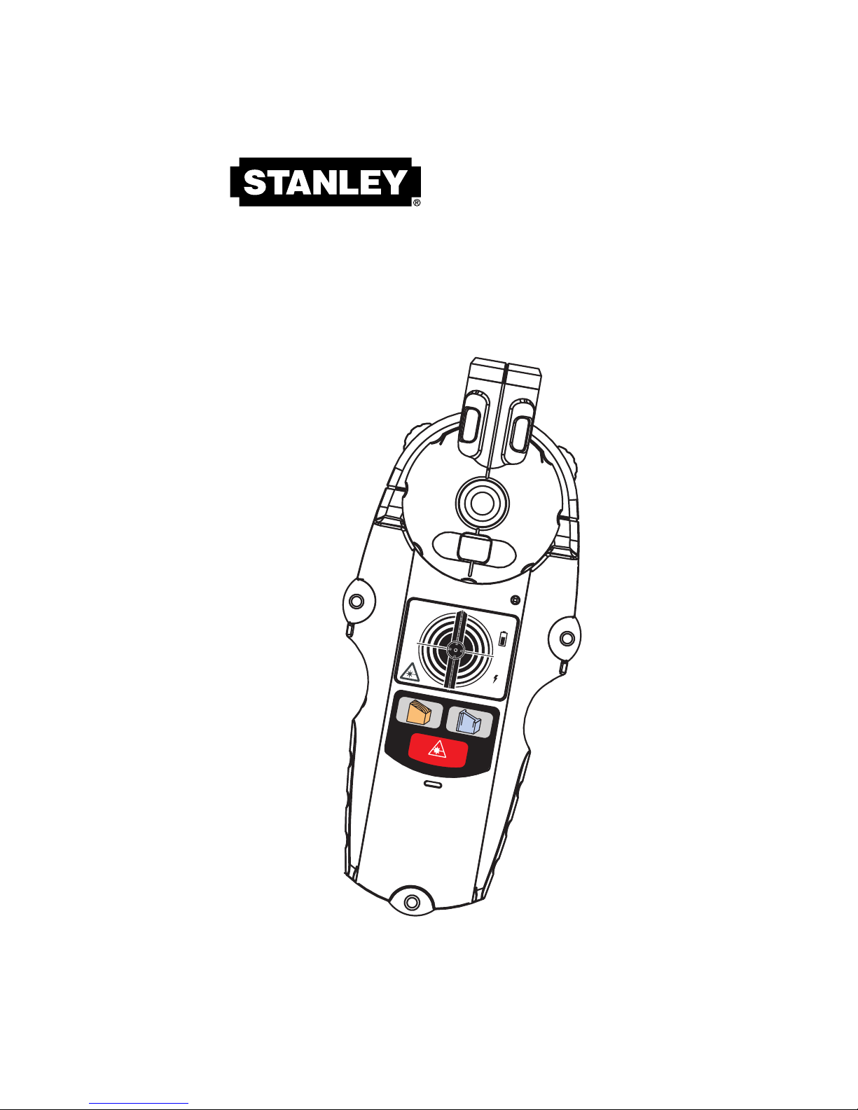
IntelliLaser Pro
Stud Finder and Laser Line Level
with Continuous
AC Warning
INSTRUCTION
MANUAL
77-260
™
M
E
T
A
L
W
O
O
D
ED
GE
M
E
T
A
L
W
O
O
D
L
A
S
E
R
Page 3
SAFETY INSTRUCTIONS:
Failure to follow warnings may result in bodily
injury.
The following warnings must be followed to avoid
injury:
• DO NOT remove warning labels.
• DO NOT use optical tools such as a transit to
view laser beam. Serious eye injury could result.
• DO NOT project the laser beam directly into the
eyes of others.
• DO NOT stare directly at the laser beam.
• DO NOT project laser beam onto a reflective
surface.
• DO NOT operate around children, or allow
children to operate.
• DO NOT disassemble the laser.
• Always turn off laser when the tool is not in use.
WARNINGS:
IMPORTANT: Read all instructions prior to operating
the IntelliLaser
™
Pro and DO NOT remove any labels
from the tool.
The 77-260 produces a straight line on the same
surface on which the tool is placed. Any reflection of
the line on another surface should be considered
reference.
–1–
DANGER
Class IIIA Laser Product
Laser radiation emitted from tool
Max. Power Output < 5mw
Wavelength: 630-670 nm
Do Not Stare Into Beam
AVOID DIRECT EYE EXPOSURE
THIS TOOL EMITS A LASER RADIATION
This caution
notice is
reminded with
a sticker
located on
one side of
the unit.
114-GB(cover,p1-12) 25/08/2003 10:49 AM Page
Page 4

IntelliLaser
™
Pro (77-260)
The Stanley®IntelliLaser™ Pro uses electronic signals
to locate the position of studs, joists or live AC wires
through drywall and other common wall materials.
Once the edge of the stud has been detected, the
IntelliLaser™ Pro LCD display gives visual and audio
indications that allow you to easily pinpoint the stud’s
edge position. A pencil line allows you to quickly note
the location of the stud edges.
The Stanley®IntelliLaser™ Pro generates a laser plane
vertically and pivoting 90 degree clockwise or counterclockwise to generate a laser straight line.
The IntelliLaser™ Pro allows the user to locate wood
and metal studs up to 3/4 inch for metal and wood
stud.
The IntelliLaser™ Pro provides automatic calibration
for metal and wood stud modes, auto shut off and
heavy duty ABS construction.
Detection mode is selected by keypad function - metal
and wood stud. Default mode is wood stud detection.
Mode should be selected before “on” key is pressed.
–2–
114-GB(cover,p1-12) 25/08/2003 10:49 AM Page
Page 5
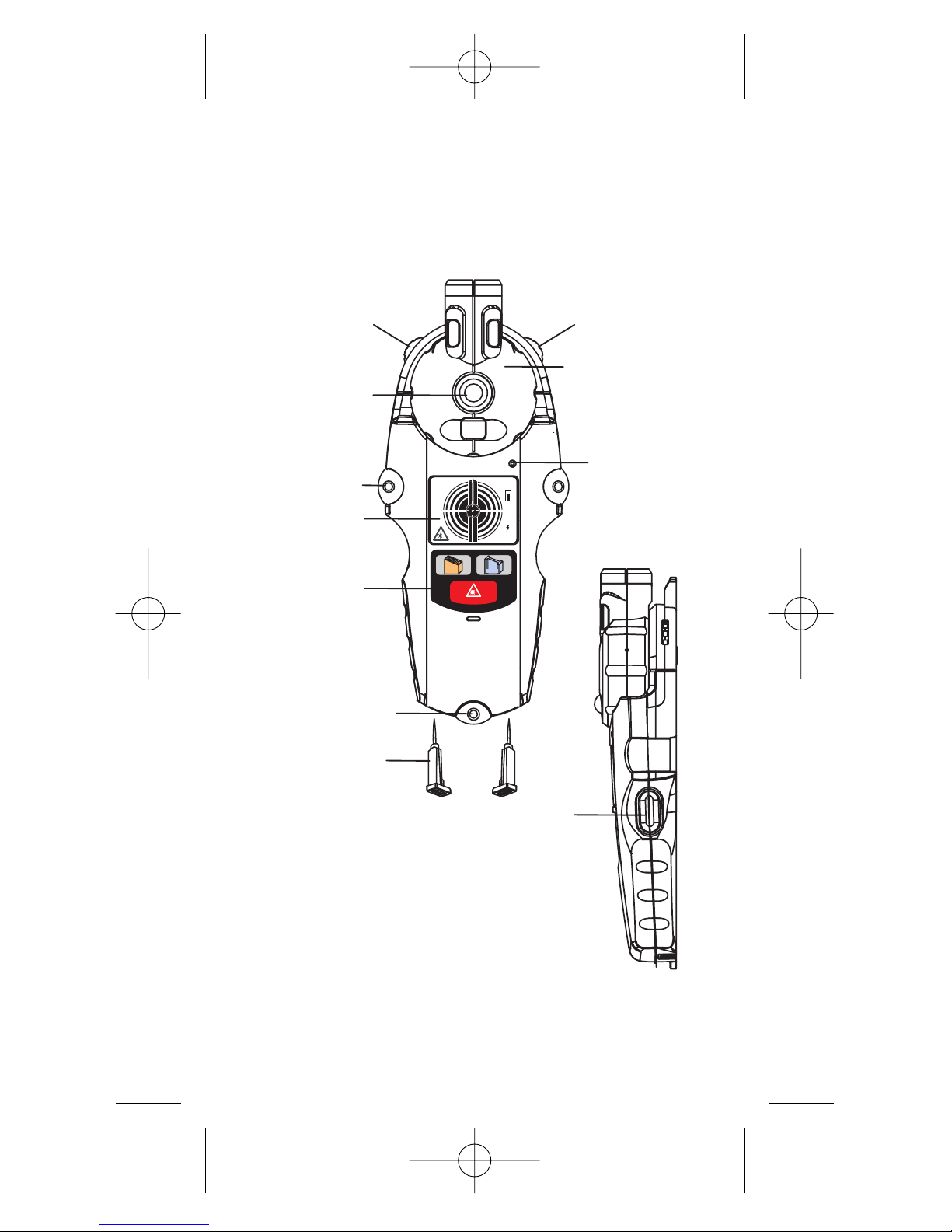
–3–
ILLUSTRATION 1
"ON"
Button
Adjustment Feet
Push Pin
Mounting Hole
Keypad
Adjustment Feet
Mounting Hole
Lock/Release
Button
Laser Plane
Live Wire
LED
LCD
METALWOOD
EDGE
M
E
T
A
L
WOOD
LASER
114-GB(cover,p1-12) 25/08/2003 10:49 AM Page
Page 6

–4–
METAL
WOOD
LASER
ILLUSTRATION 2
ILLUSTRATION 3
A: Wood Stud detection mode
B: Metal Stud detection mode
C: Laser line on/off button
Wood Metal
Laser Plane
Indicator Graphic
Laser Plane
Live Wire
Low
Battery
Indicator
METALWOOD
EDGE
B
A
C
114-GB(cover,p1-12) 25/08/2003 10:49 AM Page
Page 7

Operating Instructions
Battery Replacement
Open the battery door on back of unit
and connect a 9-volt battery to clip.
Place battery back into case and snap
battery door on. Recommend to replace
a new 9 volt battery when low battery
indicator is on.
Calibration
Calibrate the unit on wall before scanning for wood or
metal stud.
Note: While calibrating, the IntelliLaser™ Pro must
not be placed directly over a stud, dense material such
as metal, wet or newly painted areas as this will
prevent the unit from calibrating properly. If this is done
over wood or metal stud the unit will give no indication
when moved away from the area. Move to a different
location and try again.
1. Hold the IntelliLaser™ Pro flat against the surface,
making firm contact. Press and hold the “On”
button. All indicators on the LCD are displayed while
the unit goes through its’ 1 to 3 second calibration
cycle. When calibrated, and illustration 5 will be
shown on the LCD and a beep sound comes out.
2. Laser line is always on when
holding the “On” button.
3. Keep holding “On” button during
the stud detection.
–5–
IL LU S TR AT ION 4
Battery
Door
DEEP READ
WOOD
IL LU S TR AT ION 5
Page 8

USAGE
Detecting Wood Studs
Wood Stud detection is set as the default when
the unit is on.
1. Slide the unit across the surface in a straight line.
The closer the unit is to the stud the more bars will
be shown as illustration 6. When the stud edge is
detected the Wood indicator and the edge bar will
be shown as illustration 7 and the unit will sound a
repeating beep.
2. Use the indicator line to mark the stud edge.
3. Continue sliding past the stud. When the indicator
turns off and the unit stops beeping the other edge
has been detected.
4. Double check stud
location by coming
back from the
other direction.
Make additional
markings.
5. The midpoint of the marks indicates the
stud center
–6–
WOOD
IL LU S TR AT ION 6 IL LU S TR AT ION 7
WOOD
EDGE
Page 9

Detecting Metal Studs
1. Press “Metal” button once and
the LCD as shown in illustration 8.
Press & keep holding the
“On”button all the time during the
stud detection
2. Repeat the procedure 1-5 as described in“Detecting
Wood Stud”.
Detecting Live Wires
The Live Wire Detection feature is always on and the
“Live Wire” icon will be displayed on the LCD. When
a Live Wire is detected, the red live wire LED indicator
will be on.
Static electricity charges that can develop on drywall
and other surfaces will spread the voltage detection
area many inches to each side of the actual electrical
wire. To aid in locating the wire position, scan holding
the unit 1/2 inch away from the wall surface or place
other hand on surface approximately 12 inches from
sensor.
Warning: shielded wires or live wires in metal
conduits, casings, metalized walls or thick,
dense walls, will not be detected. Always turn
AC power off when working
near wiring.
The IntelliLaser
™
Pro is designed to detect 110 volts
(for USA version) and 230 volts for (European version)
AC in live electrical wires. It will also detect the
presence of live wires having greater than 230 volts.
–7–
ILLUSTRATION 8
METAL
114-GB(cover,p1-12) 25/08/2003 10:49 AM Page
Page 10

–8–
Laser Plane
1. Laser plane in the stud detection mode is
always on, a laser plane icon is also shown on
the LCD. It can be turned off by pressing “Laser”
button once.
2. Laser plane can also be turned on individually by
pressing “Laser” button once or pressing again to
turn it off.
3. The Laser plane will be auto - off after 1 hour.
4. Laser plane can be pivoted 90° degree clockwise
or counter clockwise with 45° degree detents by
pressing the laser plane lock/release button.
Mounting Hole an Push Pins
Two push pins are stored
at the bottom part of
IntelliLaser™ Pro. They are
used to mount the
IntelliLaser™ Proon the
wall through the mounting
holes when needed.
ILLUSTRATION 1
0
Push Pin
ILLUSTRATION
9
Laser aperture
Level Vial
Level Vial
Level Vial
Lock/Release
button
114-GB(cover,p1-12) 25/08/2003 10:49 AM Page
Page 11

–9–
Adjustment Feet
The adjustment feet allow the leveling of the Laser
line on the horizontal or vertical surfaces.
Cautions on Operating
You should always use caution when nailing,
cutting or drilling in walls, ceilings and floors that
may contain wiring or pipes near the surface.
Shielded, dead or non-powered wiring will
not be detected as live wires. Always
remember that studs or joists are normally spaced
16 inches or 24 inches apart and are 1-1/2 inches
in width. To avoid surprises, be aware that anything
closer together or of a different width may be an
additional stud, joist or fire break.
When working near AC electrical wires,
always turn off the power.
Operating Tips
IMPORT
ANT SAFETY NOTICE
Insure proper detection of live wires ALWAYS
hold the IntelliLaser
™
Pro in the handle area
only. Grasp between fingers and thumb while
maintaining contact with your palm.
ILLUSTRATION 11
114-GB(cover,p1-12) 25/08/2003 10:49 AM Page
Page 12

–10–
Conventional Construction
Doors and windows are commonly constructed
with additional studs and headers for added
stability. The IntelliLaser™ Pro detects the edge of
these double studs and solid headers and emits
and holds an audio signal as it crosses over them.
Surface Differences
Wallpaper—There will be no difference in the
function of the stud sensor on surfaces covered
with wallpaper or fabric unless the coverings
contain metallic foil or fibers.
Plaster and Lath — Unless the plaster and lath is
exceptionally thick or has metal mesh in it there
will be no problem with the unit functioning
properly.
Ceiling or Textured Surfaces — When dealing
with a rough surface such as a sprayed ceiling, use
a piece of cardboard when scanning the surface.
Run through the calibration technique described
earlier WITH the piece of cardboard between the
stud sensor and the surface. Also, it is particularly
important in this application to remember to keep
your free hand away from the unit.
114-GB(cover,p1-12) 25/08/2003 10:49 AM Page
Page 13

Specifications
Utilizing the procedure of scanning and marking
from two sides, IntelliLaser™ Pro will find the stud
center with 1/8” accuracy for wood and 1/4”
accuracy for metal.
When measuring a wood or metal stud, it is
recommended the IntelliSensor
™
to be used at 33-
55% relative humidity.
Battery: 9 volt (not included)
Shock Resistance: up to 3 feet
Operating Temperature: +20°F to +120°F
(-7°C to +49°C)
Storage Temperature: -20°F to +150°F
(-29°C to +66°C)
Laser diode: 650nm class IIIA
Laser accuracy: 1/2” at 20 feet
Length of projected Laser Line: up to 20 feet
This is a Class IIIA (U.S. version) or IIIR (Europe
version) laser tool and is manufactured to comply
with international safety rule IEC 285.
–11–
114-GB(cover,p1-12) 25/08/2003 10:49 AM Page
Page 14

Warranty
The Stanley Works warrants the IntelliLaser™ Pro
against defects in material and workmanship for
one year from the date of purchase. Deficient
products will be repaired or replaced at Stanley’s
discretion if sent to:
The Stanley Works
Customer Service
Repair Department
480 Myrtle Street
New Britain, CT 06053
Stanley’s liability under this warranty is limited to
repair or replacement of the unit. Any attempt to
repair the product by other than factory authorized
personnel will void this warranty. Calibration,
batteries and maintenance are the responsibility of
the user. Where permitted by law, Stanley is not
responsible for incidental or consequential
damages. Agents of Stanley cannot change this
warranty. Stanley is not responsible for damage
resulting from wear, abuse or alteration of this
product. The user is expected to follow ALL
operating instructions.
This warranty may provide you with additional
rights that vary by state, province or nation.
–12–
114-GB(cover,p1-12) 25/08/2003 10:49 AM Page
 Loading...