

Page 1
Infrastructure
Safety, Operation & Maintenance
Nuerenberg, David
Directive/Standards
No.
Approved body
Machinery Directive
2006/42/EC
Self
ID07 Hydraulic Impact Drill
49228 User Manual 11/2019 Ver. 2
DECLARATION OF CONFORMITY
ÜBEREINSTIMMUNGS-ERKLARUNG
DECLARATION DE CONFORMITE CEE
DECLARACION DE CONFORMIDAD
DICHIARAZIONE DI CONFORMITA
______________________________________________________________________
I, the undersigned:
Ich, der Unterzeichnende:
Je soussigné:
El abajo firmante:
lo sottoscritto:
hereby declare that the equipment specified hereunder:
bestätige hiermit, daß erklaren Produkt genannten Werk oder Gerät:
déclare que l’équipement visé ci-dessous:
Por la presente declaro que el equipo se especifica a continuación:
Dichiaro che le apparecchiature specificate di seguito:
Surname and First names/Familiennname und Vornamen/Nom et prénom/Nombr e y apellido/Cognome e nome
1. Category:
Kategorie:
Catégorie:
Categoria:
Categoria:
2. Make/Marke/Marque/Marca/Marca
3. Type/Typ/Type/Tipo/Tipo: ID0781001, ID0782001, ID0792001
4. Serial number of equipment:
Seriennummer des Geräts:
Numéro de série de l’équipement:
Numero de serie del equipo:
Matricola dell´attrezzatura:
Has been manufactured in conformity with
Wurde hergestellt in Übereinstimmung mit
Est fabriqué conformément
Ha sido fabricado de acuerdo con
E’ stata costruita in conformitá con
Richtlinie/Standards
Directives/Normes
Directriz/Los Normas
Direttiva/Norme
EN ISO
EN ISO
EN ISO
EN ISO
EN ISO
5. Special Provisions: None
Spezielle Bestimmungen:
Dispositions particulières:
Provisiones especiales:
Disposizioni speciali:
6. Representative in the Union: Patrick Vervier, Stanley Dubuis 17-19, rue Jules Berthonneau-BP 3406 41034 Blois Cedex, France.
Vertreter in der Union/Représentant dans l’union/Representante en la Union/Rappresentante presso l’Unione
Done at/Ort/Fait à/Dado en/Fatto a STANLEY Infrastructure, Milwaukie, Oregon USA Date/Datum/le/Fecha/Data 4-25-2018
Signature/Unterschrift/Signature/Firma/Firma
Position/Position/Fonction/Cargo/Posizione North America Quality Manager
Nr
Numéro
No
n.
28927-6
3744 (15744)
11148-6, Cl. 5.4
11148-6, Cl. 5.5
13732-1
Hydraulic Hand-Held Impact Drill
STANLEY
All
Prüfung durch
Organisme agréé
Aprobado
Collaudato
Self
Self
Self
Self
Self
Page 2
A
14
15 16
1
2
3
4
13
12
6
7
11
10
8
9
5
B
C
2 | ID07 User Manual
4
6
2
1
Page 3
D
9
4
7
5
6
E
2
3
4 5
ID07 User Manual | 3
Page 4
F
1
2
3
5
4 6 7 8
10 11 12
13
14
15
16
17
24
23
22
J-N
9
21
G
18
G
H
I
20
19
G
1 2 3
6
5
7
4
17 18
8 9
16
10 11
15
13 14
12
4 | ID07 User Manual
Page 5
H
1 2 4 5 6
3
I
6
7
2
1
3 4 5
14
13
8
10
9
11 12
ID07 User Manual | 5
Page 6

J
1 2
3 4
K
1 2
5
6
3
4
7
8 9
5
6
7 8
10
11
L
1
2
3
4
5
6 7 8
9
M
2
1
3 4
5
6 7 8 9
10
N
1
6 | ID07 User Manual
2 3
5
4
6
7
8
Page 7

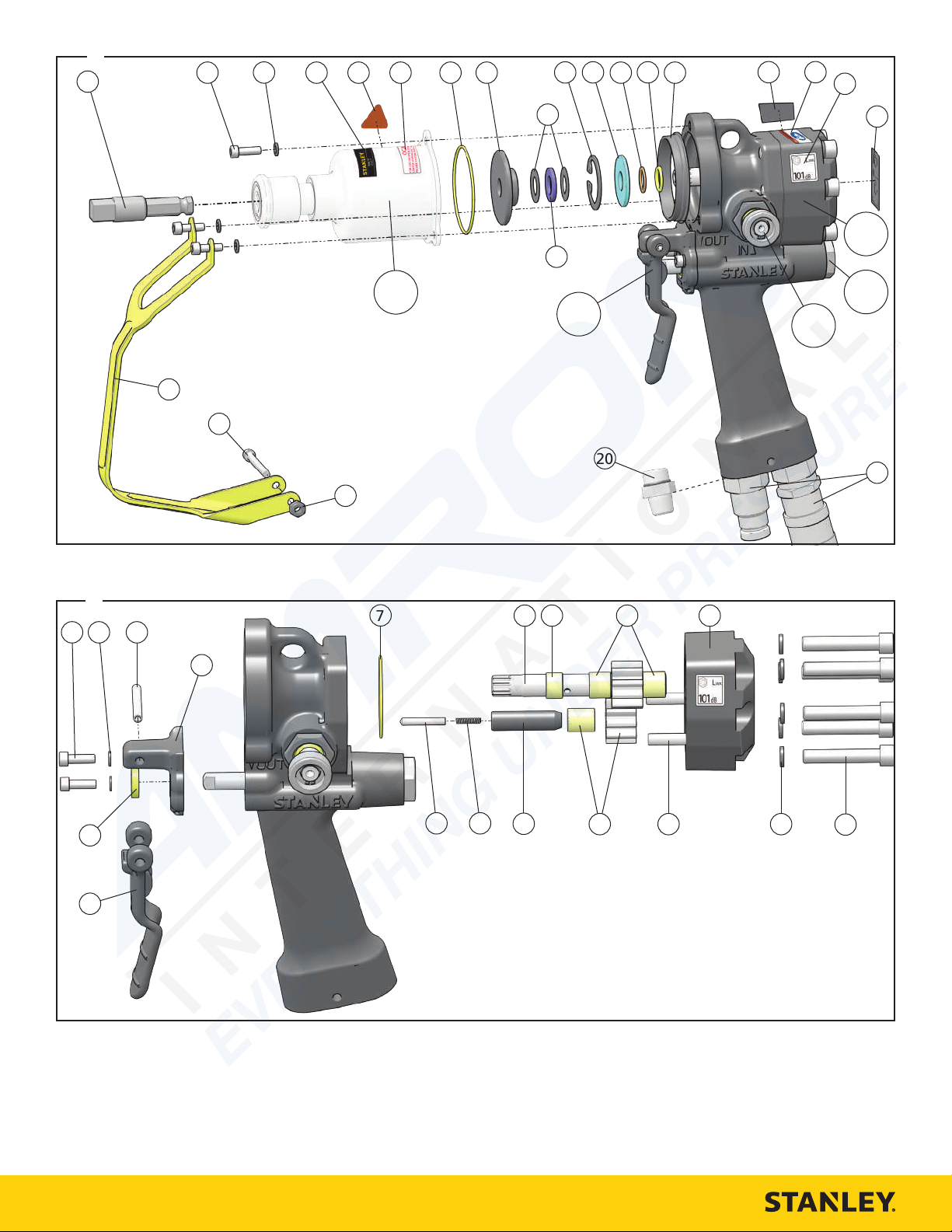
ID07 Parts Illustration - Detail F
ITEM P/N DESCRIPTION
1
05117 7/16 Inch Hex Adapter
2
62229 Cap Screw
3
09623 Lock Washer
4
74678 Tool Name Tag
5
11207 Circuit Type “D” Decal
6
11354 Open Center / Closed Center Decal
7
01205 O-ring*
8
30704 Spacer
9
20761 Bearing Race
10
06635 Retaining Ring
11
20767 Seal Back-up Washer
12
13995 Back-up Ring*
13
00354 O-ring*
14
32029 Pilot Ring
15
28323 CE Decal (CE Models)
58862 Pressure Warning Decal (Non-CE Models)
16
28788 Read the Manual Decal (CE Models)
17
81436 Sound Power Decal - Model ID0781501
29530 Sound Power Decal - Models ID0782001,
ID0792001
58864 Electrical Warning Decal - (Non-CE Models)
18
29149 Rotation Direction Decal
19
58718 Coupler Set - Models ID0781501, ID782001
03971 Coupler Set - Models ID07810S, ID0781506,
ID07815AS, ID07830K, ID0792001
81160 Coupler Set - Models ID07815AB, ID07810B
20
00936 Adapter - Models ID07810, ID07810M,
ID07815, ID0781506, ID077820, ID07830
21
20762 Bearing
22
07724 Nylock Nut - Models ID07810B, ID07810S,
ID07815, ID0781501, ID0781506, ID07815AB,
ID07815AS, ID0782001, ID0792001
23
09687 Cap Screw - Models ID07810B, ID07810S,
ID07815, ID0781501, ID0781506, ID07815AB,
ID07815AS, ID0782001, ID0792001
24
60710 Trigger Guard - Models ID07810B, ID07810S,
ID07815, ID0781501, ID0781506, ID07815AB,
ID07815AS, ID0782001, ID0792001
25
56725 Hose Assembly (not shown) - Models
ID07810S, ID07815AS
66727 Hose Assembly (not shown) - Models
ID07810B, ID07815AB
26
58973 Hose - Model ID078108
27
60791 ID07 Seal Kit (not shown) (* In seal kit)
ID07 Trigger & Motor Parts Illustration - Detail G
ITEM P/N DESCRIPTION
1
62229 Cap Screw
2
09623 Lock Washer
3
07970 Roll Pin
4
60678 Trigger Mount
5
60677 Trigger
ID07 Trigger & Motor Parts Illustration - Detail G
ITEM P/N DESCRIPTION
6
49139 Seal Wiper*
7
01262 O-ring*
8
20788 Main Shaft
9
20758 Bushing
10
05207 Bushing
11
20770 Motor Cap Assembly (Includes 1x 05207, 2x
00713)
12
18206 Cap Screw
13
00231 Lock Washer
14
00713 Dowel Pin
15
20769 Idler Gear Assembly
16
31246 Idler Shaft
17
31665 Spring
18
31299 Plunger
19
60791 ID07 Seal Kit (not shown) (* in seal kit)
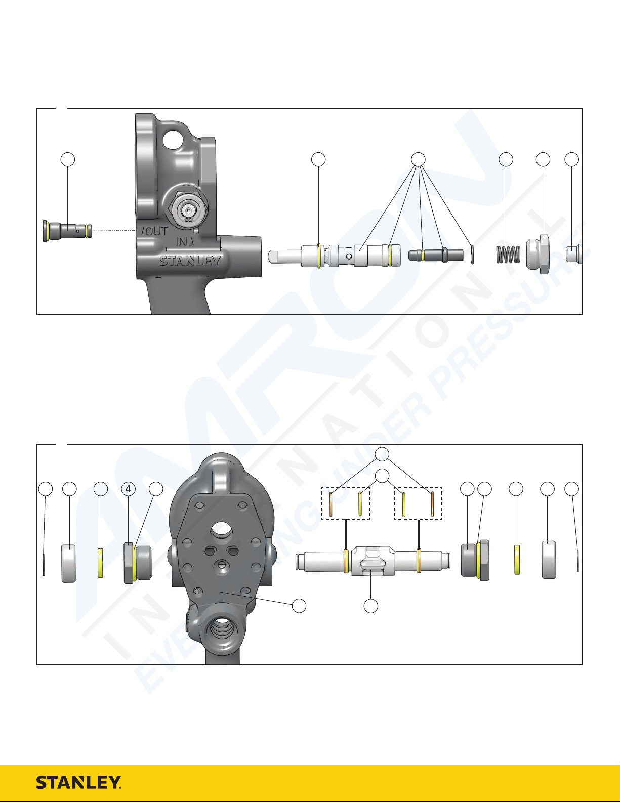
ID07 Trigger Valve Parts Illustration - Detail H
ITEM P/N DESCRIPTION
1
56721 Relief Cartridge
2
07627 O-ring*
3
48986 Valve Spool Assembly
4
65480 Spring
5
56758 Spring Cap
6
350041 Hex Plug
7
60791 ID07 Seal Kit (not shown) (* in seal kit)
ID07 Rotation Direction Valve Parts Illustration - Detail I
ITEM P/N DESCRIPTION
1
56764 Retaining Ring
2
56757 End Cap
3
56747 Seal Wiper
4
56749 Seal Cap
5
01604 O-ring*
6
07224 Back-up Ring*
7
00175 O-ring*
8
56749 Seal Cap
9
01604 O-ring*
10
56747 Seal Wiper
11
56757 End Cap
12
56764 Retaining Ring
13
56765 Reversing Spool
14
59049 Main Tool Housing Assembly
15
60791 ID07 Seal Kit (not shown) (* in seal kit)
ID07 User Manual | 7
Page 8

ID07 Impact Mechanism 31894 Parts Illustration - Detail J
Models ID07810, ID07810B, ID07810S, ID07815, ID0781501,
ID0781506, ID07815AB, ID07815AS
ITEM P/N DESCRIPTION
1
31901 Thrust Ring Lock
2
31900 Thrust Ring
3
31899 Spring
4
31902 Retaining Ring
5
31904 Hammer Case
6
31903 Hammer Case Bushing
7
15966 Steel Ball
8
31898 Anvil
9
31897 Hammer
10
31896 Hammer Frame
11
06757 Hammer Pin
ID07 Impact Mechanism 32149 Parts Illustration - Detail K
Models ID07820, ID0782001
ITEM P/N DESCRIPTION
1
31904 Hammer Case
2
31903 Hammer Case Bushing
3
08416 Spring
4
32151 Retainer
5
72900 Anvil
6
31896 Hammer Frame
7
31897 Hammer
8
06757 Hammer Pin
ID07 Impact Mechanism 67297 Parts Illustration - Detail M
Models ID07810M
ITEM P/N DESCRIPTION
7
15933 Steel Ball
8
31898 Anvil
9
31896 Hammer Frame
10
06757 Hammer Pin
ID07 Impact Mechanism 67637 Parts Illustration - Detail N
Models ID07830, ID07830K
ITEM P/N DESCRIPTION
1
31904 Hammer Case
2
31903 Hammer Case Bushing
3
72902 Anvil Friction Ring
4
72903 O-ring
5
72901 Anvil
6
31896 Hammer Frame
7
31897 Hammer
8
06757 Hammer Pin
ID07 Impact Mechanism 32284 Parts Illustration - Detail L
Models ID07920, ID0792001
ITEM P/N DESCRIPTION
1
31904 Hammer Case
2
32153 Hammer Case Bushing
3
08416 Spring
4
32151 Retainer
5
00012 O-ring*
6
72900 Anvil
7
31896 Hammer Frame
8
31897 Hammer
9
06757 Hammer Pin
10
60791 ID07 Seal Kit (not shown) (* in seal kit)
ID07 Impact Mechanism 67297 Parts Illustration - Detail M
Models ID07810M
ITEM P/N DESCRIPTION
1
31901 Thrust Ring Lock
2
31900 Thrust Ring
3
31899 Spring
4
31902 Retaining Sleeve
5
31904 Hammer Case
6
31903 Hammer Case Bushing
8 | ID07 User Manual
Page 9

Safety Precautions
The Safety Alert Symbol alerts you to potential
personal injury hazards. Obey all safety messages
that follow to avoid possible injury or death.
Indicates an imminently hazardous situation which
will result in death or serious injury.
Indicates a potentially hazardous situation which
could result in death or serious injury.
Indicates a potentially hazardous situation which
could result in property damage.
Always observe safety symbols. They are included for your safety and for the
protection of the tool.
WARNING: Read all safety warnings and instructions. Failure
to follow warnings and instructions may result in tool damage
and/or serious injury.
WARNING: To reduce the risk of injury, read the instruction
manual.
General
• Do not discard safety instructions. Give to the operator.
• This tool will provide dependable service if operated in accordance
with the instructions given in this manual. Read and understand this
manual and any stickers and tags attached to the tool and hoses before
operation. Failure to do so could result in personal injury or equipment
damage.
• Inspect the tool before each use and ensure all decals are legible.
Contact STANLEY if replacements are needed.
• Establish a training program for all operators to ensure safe operation.
Do not operate the tool unless thoroughly trained or under the
supervision of an instructor. Keep out of the reach of children.
• Operators and maintenance personnel shall be able to physically handle
the bulk, weight and power of the tool.
• Avoid unsuitable postures as these positions do not allow for
counteracting of normal or unexpected movement of the tool, such as
a sudden break of the tool bit. Change postures during extended tasks
to help avoid discomfort or fatigue.
• Do not operate a damaged, improperly adjusted, modified or
incompletely assembled tool.
• Do not operate the tool in explosive atmospheres, such as in the
presence of flammable liquids, gases or dust. Power tools create sparks
which may ignite the dust or fumes.
• Provide adequate ventilation in closed areas when operating a gas or
diesel hydraulic power source.
• Do not inspect, carry, clean, change accessories or perform
maintenance on the tool while the power source is connected.
Accidental engagement of the tool can cause serious injury.
• Ensure work piece is securely fixed. Be aware that failure of the work
piece or accessories may generate high velocity projectiles.
• Stay alert, watch what you are doing and use common sense when
operating a hydraulic tool. Do not operate this tool if you are tired or
under the influence of drugs or alcohol. A moment of inattention while
operating hydraulic tools may result in serious injury.
• Assess risks to others around you before operating the tool.
• During operation, do not contact mechanisms, accessories or hardware
as they can become very hot; use your Personal Protection Equipment
(PPE).
• Use and maintain the tool as stated in this manual. Misuse of this tool
is forbidden. Misuse of the tool can cause serious injury. Do not modify
the tool in any way.
• Supervising personnel should develop additional precautions relating to
the specific work area and local safety regulations.
• Never operate the tool if you cannot be sure that underground utilities
are not present, such as electrical cables, gas pipes, etc. These can
cause a hazard if damaged with the tool.
• The tool is not insulated against coming into contact with electric
power. Use hose certified as non-conductive.
• Do not overreach. Maintain proper footing and balance at all times
when using the tool.
• Slips, trips and falls are major causes of workplace injury. Be observant
of hoses lying about the work area, as they can be a tripping hazard.
• Operator must start in a work area without bystanders and must assess
the risk to bystanders, including the risk of serious injury or death
caused by the tool or accessories dropped from an elevated height.
• Operators must be familiar with all prohibited work areas such as
excessive slopes and dangerous terrain conditions.
• Only use clean hydraulic fluid and lubricants that have been
recommended by STANLEY.
• Ensure tools are working properly and safely by performing preventative
maintenance (PM) procedures.
• Repair and service of this tool must only be performed by an authorized
and certified dealer.
• Use only replacement parts recommended by STANLEY.
• Do not force the tool to do the work of a larger tool. Use the correct
tool for your application.
• Use only hoses and hose couplings that are rated for a minimum
working pressure of 2500 PSI (172 BAR).
• Keep hands away from rotating chuck, drill bits or drives.
• Rotating drive sockets and drive extensions can easily entangle rubbercoated gloves or metal reinforced gloves. Never hold the drive, sockets,
drive extensions or other accessories.
• Do not use in confined spaces. Beware of crushing hazards between the
tool and the workpiece, especially when unscrewing or reversing the
tool.
• Keep the work area well lit.
• Prevent unintentional starting. Ensure the trigger is in the off position
before connecting to power source, picking up or carrying the tool.
Carrying power tools with your finger on the trigger or energizing
power tools that have the trigger on invites accidents.
• In spite of the application of relevant safety regulations and the
implementation of safety devices, certain residual risks cannot be
avoided. These risks are: repetitive strain injury due to incorrect posture
and risk of pinching fingers when changing tool bit or pressing trigger.
Dust and Fumes
• WARNING: Some dust created by power sanding, sawing, grinding,
drilling, and other construction activities contains chemicals known
to the State of California to cause cancer, birth defects or other
reproductive harm. Some examples of these chemicals are:
• Lead from lead-based paints,
• crystalline silica from bricks and cement and other masonry
products, and
• arsenic and chromium from chemically-treated lumber.
Your risk from these exposures varies, depending on how often you do
this type of work. To reduce your exposure to these chemicals: work in
a well ventilated area, and work with approved safety equipment, such
as those dust masks that are specially designed to filter out microscopic
particles.
Protect yourself and those around you. Research and understand the
materials you are drilling. Follow correct safety procedures and comply
with all applicable national, state or provisional health and safety
regulations relating to them, including, if appropriate arranging for the
safe disposal of the materials by a qualified person.
• When dust or fumes are created, control them at the point of emission.
Direct tool exhaust to minimize disturbance of dust.
• Operate and maintain the tool as recommended in this manual to
minimize dust.
• Use respiratory protection in accordance with employers instruction or
as required by occupational health and safety regulations.
• Avoid prolonged contact with dust. Allowing dust to get into your
mouth, eyes or lay on the skin may promote absorption of harmful
chemicals.
• Select and replace tool bits as recommended in order to prevent an
unnecessary increase in dust or fumes.
• Keep tool handles dry, clean and free from oil and grease. This will
enable better control of the tool.
PPE
• Always wear safety equipment such as impact resistant goggles, ear
protection, head protection, breathing protection and safety shoes at all
times when operating the tool.
• Hands may be exposed to hazards, impacts, cuts, abrasions and heat.
Wear gloves.
• Wear a hardhat if performing overhead work.
• Use PPE that conforms to standards ANSI Z87.1 (Eye and Face
ID07 User Manual | 9
Page 10

Protection), ANSI Z89.1 (Head Protection), ANSI Z41.1 (Foot Protection)
Protection
Protection
Wear a Mask
and ANSI S12.6 (S3.19) (Hearing Protection).
• Do not wear loose fitting clothing, jewelry or gloves with cut or frayed
fingers when operating the tool. Entanglement, choking, scalping and
laceration can occur if loose clothing, personal jewelry, neck wear, hair
or gloves are not kept away from the rotating tool and it’s accessories.
Gloves can become entangled with the rotation drive, causing severed
or broken fingers.
M003
Wear Ear
M004
Wear Eye
M016
Sound
• Exposure to high noise levels can cause permanent, disabling hearing
loss and other problems, such as tinnitus (ringing, buzzing, whistling
or humming in the ears). Use hearing protection in accordance with
employer’s instructions and as required by occupational health and
safety regulations. Appropriate controls to reduce the risk can include
actions such as damping materials to prevent work pieces from
“ringing”.
• Use and maintain as recommended in the manual to prevent an
unnecessary increase in noise levels.
Vibration
• When using a rotary or percussive tool to perform work related
activities, the operator can experience discomfort in the hands, arms,
shoulders, neck or other parts of the body.
• If you experience numbness, tingling, pain or whitening of the skin
in your fingers or hands, stop using the tool. Tell your employer and
consult a physician.
• Wear warm clothing when working in cold conditions and keep your
hands warm and dry.
• Exposure to vibration can cause disabling damage to the nerves and
blood supply of the hands and arms.
• Do not use worn or ill-fitting sockets or extensions, as this is likely to
cause a substantial increase in vibration.
• Do not touch sockets or accessories during impacting. This increases the
risk of cuts, burns or vibration injuries.
• Use and maintain as recommended in the manual to prevent an
unnecessary increase in vibration.
• Check the vibration level after each service. If higher than normal,
contact your STANLEY dealer.
Hydraulic
• Warning: Hydraulic fluid under pressure could cause skin injection
• Do not let hydraulic oil get on the skin. Hydraulic oil is hot. Wear
• If exposed to hydraulic fluid, wash hands immediately.
• Do not exceed the maximum relief valve setting stated on the tool.
• Inspect and clean couplers before use, daily. Replace damaged couplers
• Hydraulic circuit control valve must be OFF before coupling or
• Ensure the couplers are properly connected and are tight.
• Do not operate the tool at fluid temperatures above 140°F (60°C).
• Do not exceed the rated flow and pressure as stated on the tool. Rapid
10 | ID07 User Manual
injury. Do not check for leaks with your hands. If you are injured by
hydraulic fluid, get medical attention immediately.
Personal Protection Equipment (PPE) at all times.
immediately.
uncoupling tools. Failure to do so may damage the couplers and cause
overheating of the hydraulic system.
Higher temperatures can cause operator discomfort and damage to the
tool.
failure of the internal seals may result.
Page 11

What is the ID07 Hydraulic Impact Drill?
ID07 is a high torque impact wrench used for tightening nuts, driving lag
bolts or auguring through difficult materials, such as telephone poles.
Specifications
Pressure 2000 PSI (140 BAR)
Flow 4-12 GPM (15-46 LPM)
RPM 7679 @ 12 GPM (46 LPM)
Max. Pressure 2500 PSI (172 BAR)
Max. Relief Pressure 2100 PSI (145 BAR)
Recommended Back
Pressure
Couplers 3/8 Inch, NPT Pipe Fitting
Port Size -8 SAE O-ring
Tool Weight 7 Lbs. (3.2 Kg)
Tool Size 13 Inches x 5 Inches x 12 Inches
Max. Hydraulic Oil
Temperature
HTMA/EHTMA Category Type II - Category D
Underwater Tool Max.
Depth
Recommended Hose Diameters for Underwater Applications
Depth 8 GPM (30 LPM) 12 GPM (45 LPM)
100 Feet (31 Meters) 5/8 Inches (16 mm) 5/8 Inches (16 mm)
300 Feet (91 Meters) 3/4 Inches (19 mm) 1 Inch (25.4 mm)
600 Feet (183 Meters) 1 Inch (25.4 mm) 1 Inch (25.4 mm)
1000 Feet (305 Meters) 1 Inch (25.4 mm) 1 1/4 Inches (32 mm)
250 PSI (17 BAR) - Can be used with higher
back pressures with reduced seal life.
140°F (60°C)
1000 Feet (305 M)
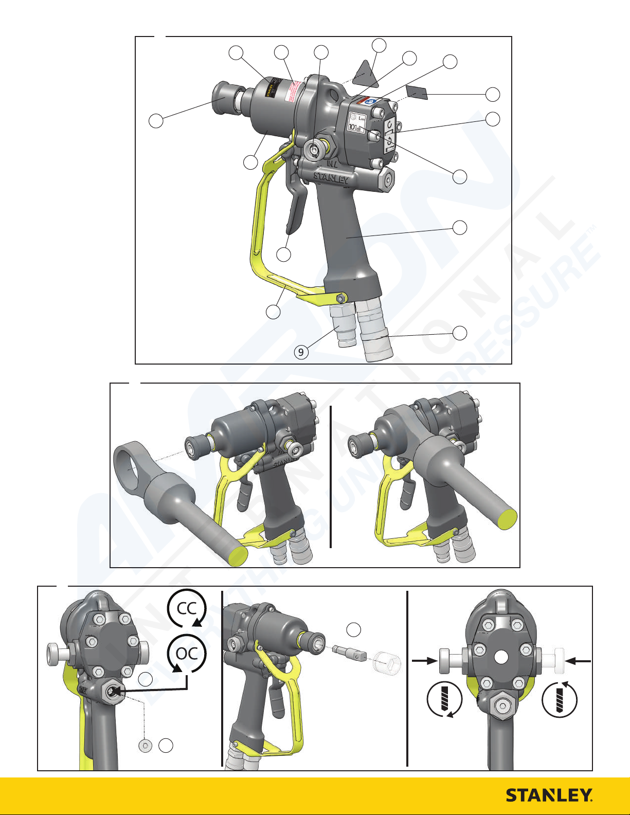
11
Trigger
12
Impact Mechanism
13
Bit Retainer
14
Tool Name Tag
15
Open Center / Closed Center Decal
16
Rotation Direction Spool
Tool Setup
Do not install or change tool accessories while the
hydraulic power source is connected. Accidental
engagement of the tool can cause serious injury.
Disconnect the hydraulic power source before installing
or changing accessories.
1. Disconnect the tool from the hydraulic power source.
Install the Assist Handle - Detail B
ID07 may be equipped with an assist handle as an accessory (see “ID07
Accessories” on page 12). The assist handle helps to absorb reaction
torque and control the tool. Loss of control can cause personal injury.
STANLEY recommends you use the assist handle whenever possible.
1. Place the assist handle over the hammer case.
2. Tighten the handle.
Set Hydraulic Circuit Type - Detail C
1. Remove the hex plug on the back of the tool handle.
2. Turn the selector screw completely clockwise for open center operation
-OR- completely counter clockwise for closed center operation.
3. Reinstall the hex plug.
Sound & Vibration Declaration
Measured A-Weighted sound power
level
Uncertainty 3.39 dBA
Measured A-Weighted Sound Pressure 93.1 dBA
Uncertainty 3.39 dBA
Values determined according to noise test code given in ISO 15744, 11203
and 3744.
Declared vibration emission value in accordance with EN ISO 28927-2.
Declared Vibration Emission Value: 8.5 m/sec²
Uncertainty 1.74 m/sec²
101.1 dBA
Parts of an ID07 - Detail A
1
Circuit Type “D” Decal
2
Serial Number & Year of Manufacture
3
Read the Manual Decal (CE Models)
4
CE Decal (CE Models)
Pressure Warning Decal (Non-CE Models)
5
Rotation Direction Decal
6
Sound Power Decal (CE Models)
Electrical Warning Decal (Non-CE Models)
7
Handle
8
Female Hydraulic Coupler
9
Male Hydraulic Coupler
10
Trigger Guard
Insert Bit - Detail C
Use only impact-rated sockets and accessories. Do not
use sockets or accessories that are in poor condition.
These can crack or fracture during operation and can
become a projectile.
4. Insert the bit while pushing back on the tool retaining sleeve.
5. Lock the tool retaining sleeve in place.
Note: Never operate the tool unless the inserted bit is properly retained. Bits
can become a high velocity projectile.
Choose Drill Rotation Direction - Detail C
6. Push the rotation direction spool left for clockwise bit rotation -OR-
right for counter clockwise bit rotation.
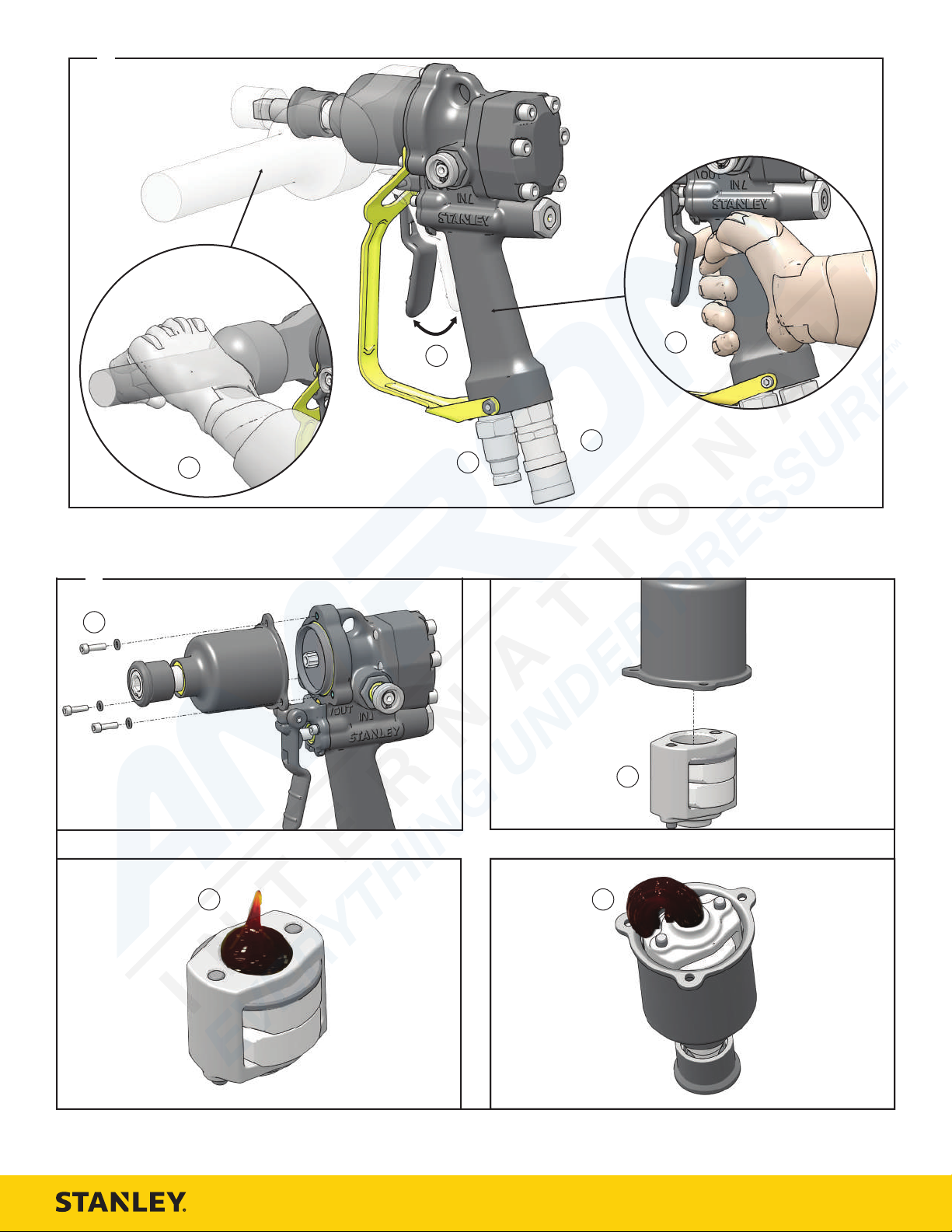
Tool Operation - Detail D
Connect to a Hydraulic Power Source
1.
Using a calibrated flow and pressure gauge, check the output of the
hydraulic power source. Ensure it matches the flow and pressure in
“Specifications” on page 11. Hydraulic fluid must be 50°F or above.
Preheat if necessary.
Note: Check the hydraulic power source once a day. Proper flow and
pressure are critical to maintaining proper tool speed.
2. Ensure that the hydraulic power source is equipped with a relief valve
set to open at the maximum relief pressure, see “Specifications” on
page 11.
Wipe hose couplers with a clean, lint free cloth.
3.
4. Connect the return hose to the tool port marked “Out”.
5. Connect the pressure hose to the tool port marked “In”.
Using the Tool
ID07 User Manual | 11
Page 12

Bolt Types for Use with ID07
Bolt Grade Thread Sizes
SAE Grade 2 7/16 - 7/8 Inch
SAE Grade 5 3/8 - 5/8 Inch
SAE Grade 8 3/8 - 9/16 Inch
6. Hold the main tool handle with your dominant hand.
7. Hold the assist handle with your non-dominant hand.
8. Place the socket or accessory on the material or fastener.
9. Squeeze the trigger.
Note: Hold the tool correctly and be ready to counteract normal or sudden
movements. Have both hands available. High reaction torque can develop if
the tool stalls, which can be caused by excessive loads being applied to the
drill bit, by the drill snagging on the material being drilled into or by the drill
bit breaking through the material being drilled.
10. Release the trigger to stop the tool.
Note: If you encounter a breakdown or the tool stops for any reason, release
the trigger and power down the hydraulic power source.
Tool Use Tips
• Heavy, loose or multiple adapters can dissipate the intensity of impact.
Use as few adapters as possible and ensure they fit tightly. Loose fitting
sockets will increase vibration.
• Hold the tool with a light, but safe grip. Risk from vibration is greater
with higher grip force.
• Maximum torque can be obtained by continuously impacting for 10
seconds.
• Hydraulic flow and pressure from the hydraulic power source will
dramatically influence the tool impact force and speed. Regularly check
the hydraulic power source. See “Specifications” on page 11.
Tool Maintenance
Daily Maintenance
1. Remove hydraulic power from the tool
2. Check all hydraulic connections and hoses for damage. Replace
damaged parts before operating the tool.
3. Inspect the tool retainer and associated parts. Replace when they have
become worn, cracked or distorted.
4. Inspect tool to ensure all decals are legible. Contact STANLEY if
replacements are needed.
Grease the Impact Mechanism - Detail E
Grease the impact mechanism if ID07 shows signs of reduced impact force.
For underwater models, grease after every use.
Regrease the impact mechanism regularly. A dry impact
mechanism can create sparks and may damage the tool.
1. Remove hydraulic power from the tool.
2. Remove the 3 cap screws that hold the impact housing to the tool body.
3. Turn the impact housing over into your hand. Lift the housing and the
impact mechanism will fall into your hand.
4. Fill the cavity with clean premium lithium complex grease.
Note: STANLEY recommends Mobile Delvax Xtreame grease.
5. Put the impact mechanism back into the impact housing. Grease will
extrude out of the bottom hole of the impact mechanism.
6. Put the impact housing assembly back onto the tool body.
Underwater Tool Maintenance
Perform maintenance on underwater models after each use.
1. Remove hydraulic power from the tool.
2. Clean and grease the impact mechanism. See “Grease the Impact
Mechanism - Detail E” on page 12.
3. Using a water displacing oil, spray into the trigger.
4. Spray or dip the entire tool.
Tool Storage & Transport
Drain the tool of hydraulic fluid and plug open hydraulic ports. Collect all
hydraulic fluid for recycling (see “Tool Disposal” on page 12). Clean the
tool and store in a clean, dry space that is safe from damage. Ensure the tool
is secured and will not move during transport. An unsecured tool could cause
personal injury or damage to the tool.
Tool Disposal
Hydraulic Oil
Hydraulic oil can contaminate the air, ground and water if not properly
recycled. Recycle hydraulic oil in accordance with all State, Federal and local
laws, at your local oil recycling facility.
Hydraulic Hoses
Hang hydraulic hoses to drain. Collect the oil for recycling. Contact your local
municipal recycling authorities for an approved hydraulic hose recycling site.
Tool Body
Drain hydraulic oil from the tool, making sure to collect the oil for recycling.
Disassemble the tool and dispose of all non-metal parts. Recycle the metal
components. Contact your local municipal recycling authorities for recycling
instructions.
Accessories
ID07 Accessories
Description Part Number
Assist Handle 73636
7/16 Inch Quick Change Chuck to 1/2 Inch
Square, Female
7/16 Inch Hex Shank to 1/2 Inch Square Adapter,
Male
5/8 Inch Quick Change Adapter to 1/2 Inch
Square, Female
5/8 Inch Male Hex x 1/2 Inch Male Square Drive 05080
1/2 Inch Square Drive Sockets
Description Part Number
9/16 Inch, Double Square, 8 Point Deep Length 05109
5/8 Inch, Double Square, 8 Point Deep Length 05110
1/16 Inch, Double Square, 8 Point Deep Length 05111
3/4 Inch, Double Square, 8 Point Deep Length 05112
13/16 Inch, Double Square, 8 Point Deep Length 05113
7/8 Inch, Double Square, 8 Point Deep Length 05114
15/16 Inch, Double Square, 8 Point Deep Length 05115
1 Inch, Double Square, 8 Point Deep Length 05116
Linemans Socket, 13/16 & 15/16 Inch 33155
Linemans Socket, 1 & 1 1/8 Inch 33156
Carbide Tipped Wood Auger Bits - 5/8 Inch Hex
Ø Length
9/16 Inch 18 Inch 22 Inch 27845
13/16 Inch 18 Inch 22 Inch 27847
Carbide Tipped Wood Auger Bits - 7/16 Inch Hex
Ø Length
9/16 Inch 8 Inch 12 Inch 27850
11/16 Inch 8 inch 12 Inch 27851
Overall
Length
Overall
Length
05079
05117
07192
Part Number
Part Number
12 | ID07 User Manual
Page 13

Carbide Tipped Wood Auger Bits - 7/16 Inch Hex
Ø Length
13/16 Inch 8 Inch 12 Inch 27852
15/16 Inch 8 Inch 12 Inch 27853
1 1/16 Inch 8 Inch 12 Inch 27854
9/16 Inch 12 Inch 16 Inch 27855
11/16 Inch 12 Inch 16 Inch 27856
13/16 Inch 12 Inch 16 Inch 27857
15/16 Inch 12 Inch 16 Inch 27858
1 1/16 Inch 12 Inch 16 Inch 27859
9/16 Inch 18 Inch 22 Inch 27860
11/16 Inch 18 Inch 22 Inch 27861
13/16 Inch 18 Inch 22 Inch 27862
15/16 Inch 18 Inch 22 Inch 27863
1 1/16 Inch 18 Inch 22 Inch 27864
13/16 Inch 36 Inch 48 Inch 27869
Overall
Length
Part Number
Troubleshooting
Problem Possible Cause Solution
Ensure the power
source is delivering
Tool will not start, is
running too fast or too
slow.
Tool has low impact
performance.
Hydraulic oil is too hot
or the hydraulic power
unit is working too
hard when running the
tool.
Oil is leaking from
the reversing spool or
motor cap.
The hydraulic power
source is not running
or not running
properly.
The hydraulic power
source is not running
or not running
properly.
Hydraulic hoses are
reversed.
Defective quick
disconnects.
Incorrect grease in the
impact mechanism
or the mechanism
maintenance hasn’t
been performed.
Motor or impact
mechanism failure.
Hydraulic circuit type
set incorrectly.
Hydraulic power source
is not running properly.
Relief valve is set too
low.
Hydraulic hoses
incorrectly connected
to the tool.
Damaged O-Rings,
loose fasteners or
other damage.
proper flow and
pressure. See
“Specifications” on
page 11. Proper
flow and pressure
maintain proper tool
speed. Check regularly.
Ensure the power
source is delivering
proper flow and
pressure. See
“Specifications” on
page 11. Proper
flow and pressure
maintain proper tool
speed. Check regularly.
Install hydraulic hoses
properly. See “Connect
to a Hydraulic Power
Source” on page 11.
Inspect for damage or
blockage. Replace if
necessary.
Grease the impact
mechanism. See
“Grease the Impact
Mechanism - Detail E”
on page 12.
Contact your STANLEY
dealer for service.
Ensure the hydraulic
circuit type on the tool
is set to match your
hydraulic system. See
“Set Hydraulic Circuit
Type - Detail C” on
page 11.
Ensure the power
source is delivering
proper flow and
pressure. See
“Specifications” on
page 11. Proper
flow and pressure
maintain proper tool
speed. Check regularly.
Ensure your hydraulic
system relief valve
is set properly. See
“Specifications” on
page 11.
Ensure the return and
pressure hoses are
properly attached to
the tool. See “Connect
to a Hydraulic Power
Source” on page 11.
Contact your STANLEY
dealer for service.
ID07 User Manual | 13
Page 14

Page 15

Page 16

STANLEY Infrastructure
6430 SE Lake Road, Portland, Oregon 97222 USA
(503) 659-5660 / Fax (503) 652-1780
www.stanleyinfrastructure.com
 Loading...