

Page 1
ID07
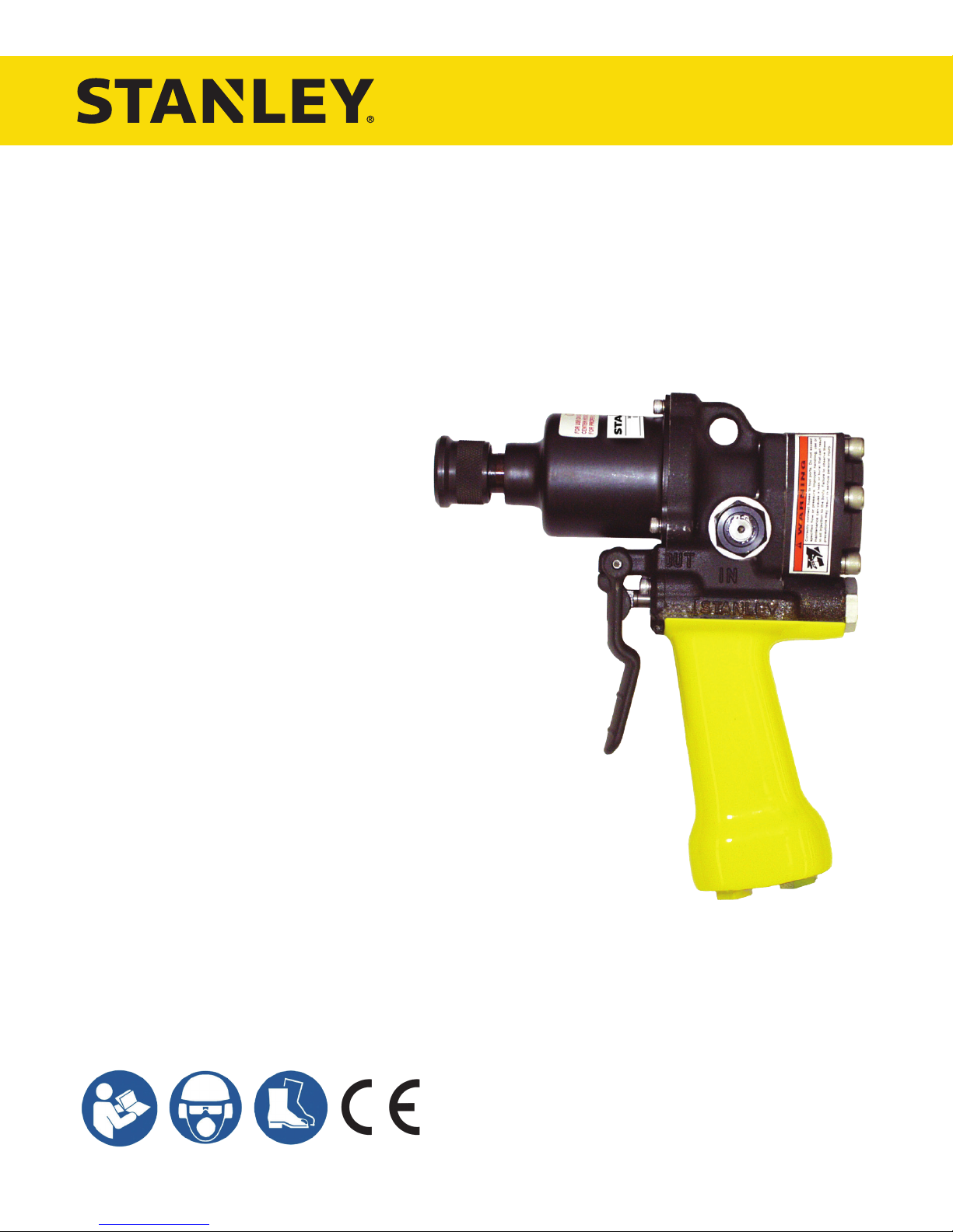
HYDRAULIC
IMPACT DRILL
USER MANUAL
Safety, Operation and Maintenance
© 2012 STANLEY Black & Decker, Inc.
New Britain, CT 06053
U.S.A.
49228 9/2018 Ver. 23
Page 2
DECLARATION OF CONFORMITY
Nuerenberg, David
Directive/Standards
No.
Approved body
Machinery Directive
2006/42/EC
Self
DECLARATION OF CONFORMITY
ÜBEREINSTIMMUNGS-ERKLARUNG
DECLARATION DE CONFORMITE CEE
DECLARACION DE CONFORMIDAD
DICHIARAZIONE DI CONFORMITA
______________________________________________________________________
I, the undersigned:
Ich, der Unterzeichnende:
Je soussigné:
El abajo firmante:
lo sottoscritto:
hereby declare that the equipment specified hereunder:
bestätige hiermit, daß erklaren Produkt genannten Werk oder Gerät:
déclare que l’équipement visé ci-dessous:
Por la presente declaro que el equipo se especifica a continuación:
Dichiaro che le apparecchiature specificate di seguito:
Surname and First names/Familiennname und Vornamen/Nom et pr énom/Nombre y apellido/Cognome e nome
1. Category:
Kategorie:
Catégorie:
Categoria:
Categoria:
2. Make/Marke/Marque/Marca/Marca
3. Type/Typ/Type/Tipo/Tipo: ID0781001, ID0782001, ID0792001
4. Serial number of equipment:
Seriennummer des Geräts:
Numéro de série de l’équipement:
Numero de serie del equipo:
Matricola dell´attrezzatura:
Has been manufactured in conformity with
Wurde hergestellt in Übereinstimmung mit
Est fabriqué conformément
Ha sido fabricado de acuerdo con
E’ stata costruita in conformitá con
Richtlinie/Standards
Directives/Normes
Directriz/Los Normas
Direttiva/Norme
EN ISO
EN ISO
EN ISO
EN ISO
EN ISO
Nr
Numéro
No
n.
28927-6
3744 (15744)
11148-6, Cl. 5.4
11148-6, Cl. 5.5
13732-1
STANLEY
Hydraulic Hand-Held Impact Drill
All
Prüfung durch
Organisme agréé
Aprobado
Collaudato
Self
Self
Self
Self
Self
5. Special Provisions: None
Spezielle Bestimmungen:
Dispositions particulières:
Provisiones especiales:
Disposizioni speciali:
6. Representative in the Union: Patrick Vervier, Stanley Dubuis 17-19, rue Jules Berthonneau-BP 3406 41034 Blois Cedex, France.
Vertreter in der Union/Représentant dans l’union/Representante en la Union/Rappresentante presso l’Unione
Done at/Ort/Fait à/Dado en/Fatto a STANLEY Infrastructure, Milwaukie, Oregon USA Date/Datum/le/Fecha/Data 4-25-2018
Signature/Unterschrift/Signature/Firma/Firma
Position/Position/Fonction/Cargo/Posizione North America Quality Manager
2 ► ID07 User Manual
Page 3
TABLE OF CONTENTS
SAFETY SYMBOLS .................................................................................................................................................4
SAFETY PRECAUTIONS .......................................................................................................................................5
TOOL STICKERS & TAGS ......................................................................................................................................7
HOSE TYPES ..........................................................................................................................................................8
HOSE RECOMMENDATIONS ................................................................................................................................9
HTMA / EHTMA REQUIREMENTS ......................................................................................................................10
OPERATION .......................................................................................................................................................... 11
TOOL PROTECTION & CARE .............................................................................................................................. 15
IMPACT MECHANISM MAINTENANCE .............................................................................................................. 15
SPECIFICATIONS .................................................................................................................................................17
ACCESSORIES .....................................................................................................................................................18
ID07 PARTS ILLUSTRATION ...............................................................................................................................19
ID07 PARTS LIST ..................................................................................................................................................20
UNDERWATER TOOLS DEPTH GUIDELINE ..................................................................................................... 22
To ll out a product warranty validation form, and for information on your warranty,
visit www.stanleyinfrastructure.com and select the Company tab > Warranty.
Note: The warranty validation record must be submitted to validate the warranty.
SERVICING: This manual contains safety, operation and routine maintenance instructions. STANLEY Infrastructure
recommends that servicing of hydraulic tools, other than routine maintenance, must be performed by an authorized
and certied dealer. Please read the following warning.
SERIOUS INJURY OR DEATH COULD RESULT FROM THE IMPROPER REPAIR OR
SERVICE OF THIS TOOL.
REPAIRS AND / OR SERVICE TO THIS TOOL MUST ONLY BE DONE BY AN
AUTHORIZED AND CERTIFIED DEALER.
For the nearest certied dealer, call STANLEY Infrastructure at (503) 659-5660 and ask for a Customer Service Representative.
ID07 User Manual ◄ 3
Page 4
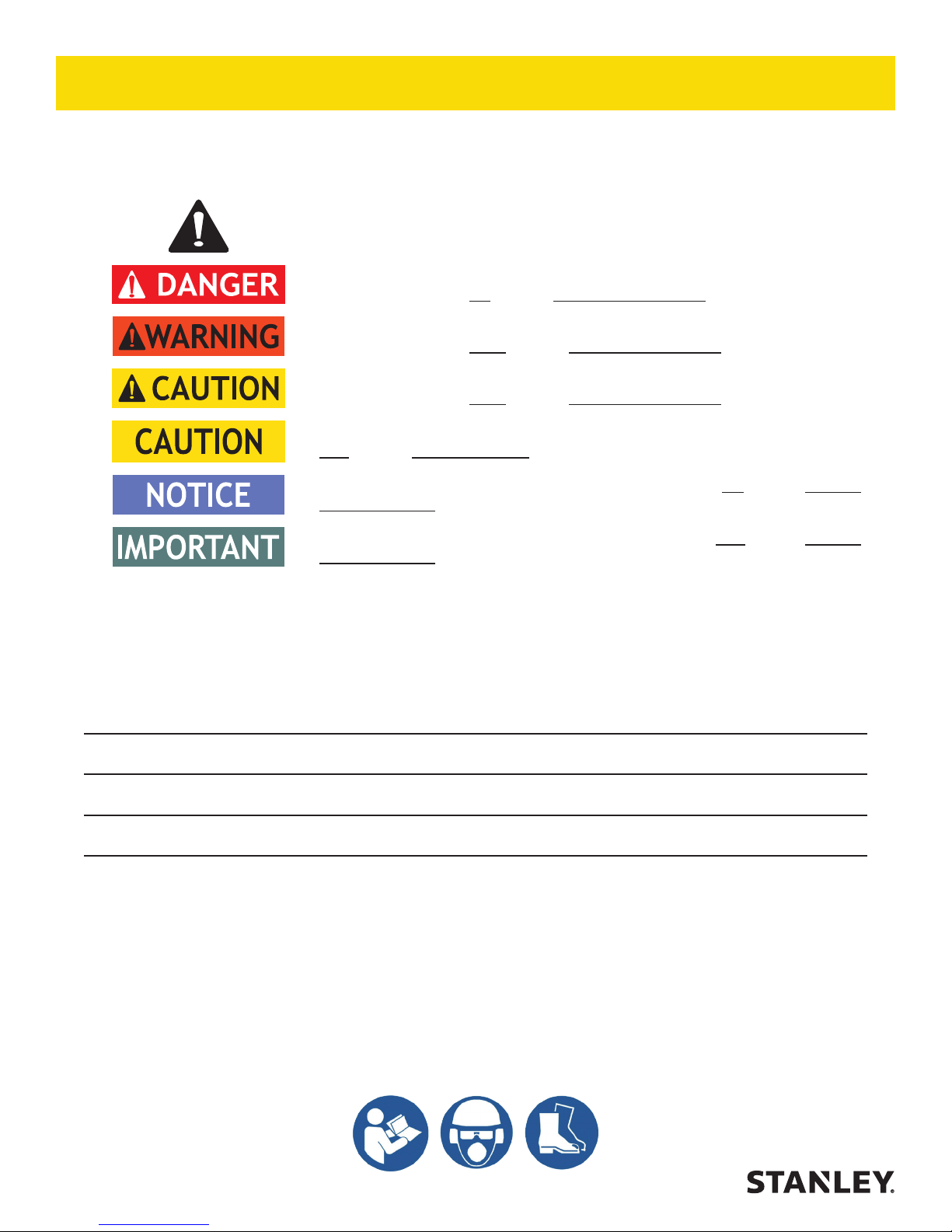
SAFETY SYMBOLS
Safety symbols and signal words, as shown below, are used to emphasize all operator, maintenance and repair
actions which, if not strictly followed, could result in a life-threatening situation, bodily injury or damage to equipment.
This is the safety alert symbol. It is used to alert you to potential personal injury
hazards. Obey all safety messages that follow this symbol to avoid possible
injury or death.
This safety alert and signal word indicates an imminently hazardous situation
which, if not avoided, will result in death or serious injury.
This safety alert and signal word indicates a potentially hazardous situation
which, if not avoided, could result in death or serious injury.
This safety alert and signal word indicates a potentially hazardous situation
which, if not avoided, could result in death or serious injury.
This signal word indicates a potentially hazardous situation which, if not avoided,
may result in property damage.
This signal word indicates a situation which, if not avoided, will result in damage
to the equipment.
This signal word indicates a situation which, if not avoided, may result in damage
to the equipment.
Always observe safety symbols. They are included for your safety and for the protection of the tool.
LOCAL SAFETY REGULATIONS
Enter any local safety regulations here. Keep these instructions in an area accessible to the operator and
maintenance personnel.
Tool operators and maintenance personnel must always comply with the safety precautions given in this manual
and on the stickers and tags attached to the tool and hose. These safety precautions are given for your safety.
Review them carefully before operating the tool and before performing general maintenance or repairs.
Supervising personnel should develop additional precautions relating to the specic work area and local safety
regulations. Place the added precautions in the space provided in this manual.
The model ID07 Hydraulic Impact Drill will provide safe and dependable service if operated in accordance with the
instructions given in this manual. Read and understand this manual and any stickers and tags attached to the tool
and hose before operation.
Failure to do so could result in personal injury or equipment damage.
4 ► ID07 User Manual
Page 5

SAFETY PRECAUTIONS
• The operator must start in a work area without
bystanders. Flying debris can cause serious injury.
• Do not operate the tool unless thoroughly trained
or under the supervision of an instructor. Establish
a training program for all operators to ensure safe
operation.
• Always wear safety equipment such as goggles,
gloves, ear, head and breathing protection, and
safety shoes at all times when operating the tool.
Use gloves and aprons when necessary.
• Inspect tool daily for loose fasteners, missing parts
and leakage. Have tool repaired if necessary.
• The operator must be familiar with all prohibited work
areas such as excessive slopes and dangerous
terrain conditions.
• Operators and maintenance personnel shall be able
to physically handle the bulk, weight and power of
the tool.
• Maintain proper footing and balance at all times and
do not overreach.
• Do not inspect or clean the tool while the hydraulic
power source is connected. Accidental engagement
of the tool can cause serious injury. Be observant
of hydraulic and water hoses lying about the work
area, they can be a tripping hazard.
• Do not use in conned spaces and beware of
crushing hands between the tool and the workpiece,
especially when unscrewing.
• Always connect hoses to the tool hose couplers
before energizing the hydraulic power source. Be
sure all hose connections are tight and are in good
condition.
• Do not operate the tool at oil temperatures above
140 °F/60 °C. Operation at higher temperatures can
cause higher than normal temperatures at the tool
which can result in operator discomfort.
• When using a rotary percussive tool to perform
work related activities, the operator can experience
discomfort in the hands, arms, shoulders, neck or
other parts of the body.
• If you experience numbness, tingling, pain or whit-
ening of the skin in your ngers or hands, stop using
the tool. Tell your employer and consult a physician.
• Check for vibration level before each service. If you
feel a higher than normal vibration, contact your
STANLEY dealer for repair.
• Do not operate a damaged, improperly adjusted or
incompletely assembled impact wrench.
• Never wear loose clothing that can become
entangled in the working parts of the tool.
• Keep all parts of your body away from the rotating
parts. Long hair or loose clothing can become drawn
into rotating components.
• Do not hold the drive, socket or drive extension
during operation. This is an entanglement hazard.
• Rotating drive sockets and drive extensions can
easily entangle rubber-coated or metal reinforced
gloves.
• Always use accessories that conform to the
specications given in the Operation section of this
manual.
• Do not reverse impact wrench rotation direction by
changing uid ow direction.
• Release the trigger if the power supply has been
interrupted.
• When working near electrical conductors, always
assume that all conductors are energized and that
insulation, clothing and hoses can conduct electricity.
Use hose labeled and certied as non-conductive.
• To avoid personal injury or equipment damage,
all tool repair, maintenance and service must only
be performed by authorized and properly trained
personnel.
• Inspect the tool before each use and ensure all decals are legible. Contact STANLEY if replacements
are needed.
• Serious injury or death could result from a tool or
accessories dropped from an elevated height. Flying
debris can cause serious injury.
• Warning: Hydraulic uid under pressure could
cause skin injection injury. If you are injured by
hydraulic uid, get medical attention immediately.
• During operation do not contact the impact
mechanism, accessories or hardware as they can
become very hot. Use your Personal Protection
Equipment (PPE).
• WARNING: Some dust created by power sanding,
sawing, grinding, drilling, and other construction
activities contains chemicals known to the State
of California to cause cancer, birth defects or
other reproductive harm. Some examples of these
chemicals are:
• Lead from lead-based paints,
• crystalline silica from bricks and cement
and other masonry products, and
• arsenic and chromium from chemically-
ID07 User Manual ◄ 5
Page 6

treated lumber.
Your risk from these exposures varies, depending
on how often you do this type of work. To reduce
your exposure to these chemicals: work in a well
ventilated area, and work with approved safety
equipment, such as those dust masks that are
specially designed to lter out microscopic particles.
Protect yourself and those around you. Research
and understand the materials you are cutting.
Follow correct safety procedures and comply with
all applicable national, state or provisional health
and safety regulations relating to them, including,
if appropriate arranging for the safe disposal of the
materials by a qualied person.
6 ► ID07 User Manual
Page 7
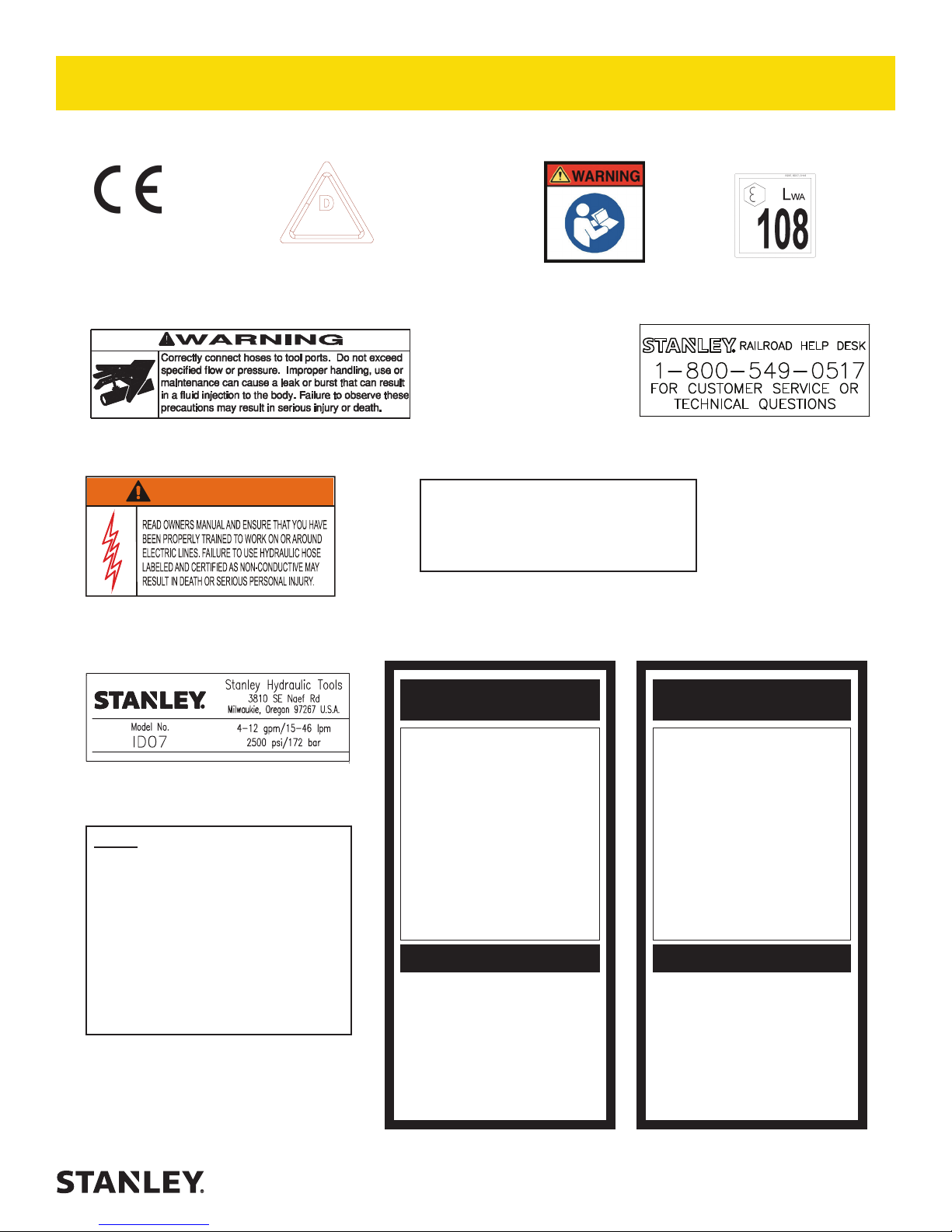
WARNING
TOOL STICKERS & TAGS
Please refer to the parts illustration for location of stickers.
Note: The serial number and year of manufacture are stamped on the tool body, above the rotation reversing spool.
D
30 LPM @ 138 BAR
28323
CE STICKER (CE)
EHTMA CATEGORY
11207
CIRCUIT TYPE D STICKER (CE)
28788
MANUAL STICKER (CE)
29530
SOUND POWER
LEVEL STICKER (CE)
58862
PRESSURE WARNING STICKER
58864
ELECTRICAL WARNING STICKER
74678
NAME TAG STICKER
NOTE
THE INFORMATION LISTED ON
THE STICKERS SHOWN, MUST
BE LEGIBLE AT ALL TIMES.
REPLACE DECALS IF THEY
BECOME WORN OR DAMAGED.
REPLACEMENTS ARE AVAILABLE
FROM YOUR LOCAL STANLEY
DISTRIBUTOR.
The safety tag (p/n 15875) at right is attached to
the tool when shipped from the factory. Read and
understand the safety instructions listed on this
tag before removal. We suggest you retain this
tag and attach it to the tool when not in use.
73680
RAILROAD HELP DESK STICKER
OC/CC
FOR USE ON OPEN CENTER AND CLOSED
CENTER HYDRAULIC
SYSTEMS. “SET FOR PROPER SYSTEM
BEFORE USE”
11354
OC/CC STICKER
1. FAILURE TO USE HYDRAULIC HOSE LABELED AND CERTIFIED AS NON-CONDUCTIVE WHEN USING HYDRAULIC
TOOLS ON OR NEAR ELECTRICAL LINES MAY RESULT IN
DEATH OR SERIOUS INJURY.
BEFORE USING HOSE LABELED AND CERTIFIED AS NON-
CONDUCTIVE ON OR NEAR ELECTRIC LINES BE SURE THE
HOSE IS MAINTAINED AS NON-CONDUCTIVE. THE HOSE
SHOULD BE REGULARLY TESTED FOR ELECTRIC CURRENT LEAKAGE IN ACCORDANCE WITH YOUR SAFETY
DEPARTMENT INSTRUCTIONS.
2. A HYDRAULIC LEAK OR BURST MAY CAUSE OIL INJECTION INTO THE BODY OR CAUSE OTHER SEVERE
PERSONAL INJURY.
A. DO NOT EXCEED SPECIFIED FLOW AND PRESSURE
FOR THIS TOOL. EXCESS FLOW OR PRESSURE MAY
CAUSE A LEAK OR BURST.
B. DO NOT EXCEED RATED WORKING PRESSURE OF
HYDRAULIC HOSE USED WITH THIS TOOL. EXCESS
PRESSURE MAY CAUSE A LEAK OR BURST.
C. CHECK TOOL HOSE COUPLERS AND CONNECTORS
DAILY FOR LEAKS. DO NOT FEEL FOR LEAKS WITH
YOUR HANDS. CONTACT WITH A LEAK MAY RESULT
IN SEVERE PERSONAL INJURY.
IMPORTANT
READ OPERATION MANUAL AND
SAFETY INSTRUCTIONS FOR THIS
TOOL BEFORE USING IT.
USE ONLY PARTS AND REPAIR
PROCEDURES APPROVED BY
STANLEY AND DESCRIBED IN THE
OPERATION MANUAL.
TAG TO BE REMOVED ONLY BY
TOOL OPERATOR.
SEE OTHER SIDE
D. DO NOT LIFT OR CARRY TOOL BY THE HOSES. DO
NOT ABUSE HOSE. DO NOT USE KINKED, TORN OR
DAMAGED HOSE.
3. MAKE SURE HYDRAULIC HOSES ARE PROPERLY CONNECTED TO THE TOOL BEFORE PRESSURING SYSTEM.
SYSTEM PRESSURE HOSE MUST ALWAYS BE CONNECTED TO TOOL “IN” PORT. SYSTEM RETURN HOSE
MUST ALWAYS BE CONNECTED TO TOOL “OUT” PORT.
REVERSING CONNECTIONS MAY CAUSE REVERSE
TOOL OPERATION WHICH CAN RESULT IN SEVERE
PERSONAL INJURY.
4. DO NOT CONNECT OPEN-CENTER TOOLS TO CLOSEDCENTER HYDRAULIC SYSTEMS. THIS MAY RESULT IN
LOSS OF OTHER HYDRAULIC FUNCTIONS POWERED BY
THE SAME SYSTEM AND/OR SEVERE PERSONAL INJURY.
5. BYSTANDERS MAY BE INJURED IN YOUR WORK AREA.
KEEP BYSTANDERS CLEAR OF YOUR WORK AREA.
6. WEAR HEARING, EYE, FOOT, HAND AND HEAD PROTECTION.
7. TO AVOID PERSONAL INJURY OR EQUIPMENT DAMAGE,
ALL TOOL REPAIR MAINTENANCE AND SERVICE MUST
ONLY BE PERFORMED BY AUTHORIZED AND PROPERLY
TRAINED PERSONNEL.
IMPORTANT
READ OPERATION MANUAL AND
SAFETY INSTRUCTIONS FOR THIS
USE ONLY PARTS AND REPAIR
PROCEDURES APPROVED BY
STANLEY AND DESCRIBED IN THE
TAG TO BE REMOVED ONLY BY
SAFETY TAG P/N 15875 (Shown smaller then actual size)
DANGERDANGER
TOOL BEFORE USING IT.
OPERATION MANUAL.
TOOL OPERATOR.
SEE OTHER SIDE
ID07 User Manual ◄ 7
Page 8

HOSE TYPES
The rated working pressure of the hydraulic hose must be equal to or higher than the relief valve setting on the
hydraulic system. There are three types of hydraulic hose that meet this requirement and are authorized for use with
STANLEY hydraulic tools. They are:
Certi ed non-conductive — constructed of thermoplastic or synthetic rubber inner tube, synthetic ber braid
reinforcement, and weather resistant thermoplastic or synthetic rubber cover. Hose labeled certifi ed non-
conductive is the only hose authorized for use near electrical conductors.
Wire-braided (conductive) — constructed of synthetic rubber inner tube, single or double wire braid
reinforcement, and weather resistant synthetic rubber cover. This hose is conductive and must never be used
near electrical conductors.
Fabric-braided (not certi ed or labeled non-conductive) — constructed of thermoplastic or synthetic rubber
inner tube, synthetic ber braid reinforcement, and weather resistant thermoplastic or synthetic rubber cover.
This hose is not certifi ed non-conductive and must never be used near electrical conductors.
HOSE SAFETY TAGS
To help ensure your safety, the following DANGER tags are attached to all hose purchased from STANLEY. DO
NOT REMOVE THESE TAGS.
If the information on a tag is illegible because of wear or damage, replace the tag immediately. A new tag may be
obtained from your STANLEY Distributor.
THE TAG SHOWN BELOW IS ATTACHED TO “CERTIFIED NON-CONDUCTIVE” HOSE
DANGER
1. FAILURE TO USE HYDRAULIC HOSE LABELED AND CERTIFIED AS NON-CONDUCTIVE
WHEN USING HYDRAULIC TOOLS ON OR NEAR ELECTRIC LINES MAY RESULT IN
DEATH OR SERIOUS INJURY.
FOR PROPER AND SAFE OPERATION MAKE SURE THAT YOU HAVE BEEN PROPERLY
TRAINED IN CORRECT PROCEDURES REQUIRED FOR WORK ON OR AROUND
ELECTRIC LINES.
2. BEFORE USING HYDRAULIC HOSE LABELED AND CERTIFIED AS NON-CONDUCTIVE
ON OR NEAR ELECTRIC LINES. WIPE THE ENTIRE LENGTH OF THE HOSE AND FITTING
WITH A CLEAN DRY ABSORBENT CLOTH TO REMOVE DIRT AND MOISTURE AND TEST
HOSE FOR MAXIMUM ALLOWABLE CURRENT LEAKAGE IN ACCORDANCE WITH SAFETY
DEPARTMENT INSTRUCTIONS.
DO NOT REMOVE THIS TAG
SEE OTHER SIDE
SIDE 1
3. DO NOT EXCEED HOSE WORKING PRESSURE OR ABUSE HOSE. IMPROPER USE
OR HANDLING OF HOSE COULD RESULT IN BURST OR OTHER HOSE FAILURE.
KEEP HOSE AS FAR AWAY AS POSSIBLE FROM BODY AND DO NOT PERMIT DIRECT
CONTACT DURING USE. CONTACT AT THE BURST CAN CAUSE BODILY INJECTION
AND SEVERE PERSONAL INJURY.
4. HANDLE AND ROUTE HOSE CAREFULLY TO AVOID KINKING, ABRASION, CUTTING, OR
CONTACT WITH HIGH TEMPERATURE SURFACES. DO NOT USE IF KINKED. DO NOT
USE HOSE TO PULL OR LIFT TOOLS, POWER UNITS, ETC.
5. CHECK ENTIRE HOSE FOR CUTS CRACKS LEAKS ABRASIONS, BULGES, OR DAMAGE TO COUPLINGS IF ANY OF THESE CONDITIONS EXIST, REPLACE THE HOSE
IMMEDIATELY. NEVER USE TAPE OR ANY DEVICE TO ATTEMPT TO MEND THE HOSE.
6. AFTER EACH USE STORE IN A CLEAN DRY AREA.
(Shown smaller than actual size)
DANGER
DANGER
SEE OTHER SIDE
SIDE 2
THE TAG SHOWN BELOW IS ATTACHED TO “CONDUCTIVE” HOSE.
DANGER
DANGER
1. DO NOT USE THIS HYDRAULIC HOSE ON OR NEAR ELECTRIC LINES. THIS HOSE IS
NOT LABELED OR CERTIFIED AS NON-CONDUCTIVE. USING THIS HOSE ON OR NEAR
ELECTRICAL LINES MAY RESULT IN DEATH OR SERIOUS INJURY.
2. FOR PROPER AND SAFE OPERATION MAKE SURE THAT YOU HAVE BEEN PROPERLY
TRAINED IN CORRECT PROCEDURES REQUIRED FOR WORK ON OR AROUND ELECTRIC LINES.
3. DO NOT EXCEED HOSE WORKING PRESSURE OR ABUSE HOSE. IMPROPER USE OR
HANDLING OF HOSE COULD RESULT IN BURST OR OTHER HOSE FAILURE. KEEP HOSE
AS FAR AWAY AS POSSIBLE FROM BODY AND DO NOT PERMIT DIRECT CONTACT
DURING USE. CONTACT AT THE BURST CAN CAUSE BODILY INJECTION AND SEVERE
PERSONAL INJURY.
4. HANDLE AND ROUTE HOSE CAREFULLY TO AVOID KINKING, CUTTING, OR CONTACT
WITH HIGH TEMPERATURE SURFACES. DO NOT USE IF KINKED. DO NOT USE HOSE TO
PULL OR LIFT TOOLS, POWER UNITS, ETC.
DO NOT REMOVE THIS TAG
SEE OTHER SIDE
SIDE 1
5. CHECK ENTIRE HOSE FOR CUTS CRACKS LEAKS ABRASIONS, BULGES, OR DAMAGE TO
COUPLINGS IF ANY OF THESE CONDITIONS EXIST, REPLACE THE HOSE IMMEDIATELY.
NEVER USE TAPE OR ANY DEVICE TO ATTEMPT TO MEND THE HOSE.
6. AFTER EACH USE STORE IN A CLEAN DRY AREA.
(Shown smaller than actual size)
DANGER
SEE OTHER SIDE
SIDE 2
DO NOT REMOVE THIS TAG
DO NOT REMOVE THIS TAG
8 ► ID07 User Manual
Page 9

Min. Working Pressure
USE
Press/Return)
(
HOSE RECOMMENDATIONS
Certi ed Non-Conductive Hose - Fiber Braid - for Utility Bucket Trucks
Oil Flow Hose Lengths Inside Diameter
GPM LPM FEET METERS INCH MM PSI BAR
4-9 15-34 up to 10 up to 3 3/8 10 Both 2250 155
Conductive Hose - Wire Braid or Fiber Braid -DO NOT USE NEAR ELECTRICAL CONDUCTORS
4-6 15-23 up to 25 up to 7.5 3/8 10 Both 2500 175
4-6 15-23 26-100 7.5-30 1/2 13 Both 2500 175
5-10.5 19-40 up to 50 up to 15 1/2 13 Both 2500 175
5-10.5 19-40 51-100 15-30 5/8 16 Both 2500 175
5/8 16 Pressure 2500 175
3/4 19 Return 2500 175
5-10.5 19-40 100-300 30-90
10-13 38-49 up to 50 up to 15 5/8 16 Both 2500 175
5/8 16 Pressure 2500 175
3/4 19 Return 2500 175
10-13 38-49 51-100 15-30
3/4 19 Pressure 2500 175
1 25.4 Return 2500 175
10-13 38-49 100-200 30-60
5/8 16 Pressure 2500 175
13-16 49-60 up to 25 up to 8
3/4 19 Return 2500 175
3/4 19 Pressure 2500 175
1 25.4 Return 2500 175
13-16 49-60 26-100 8-30
PRESSURE
<<< FLOW
RETURN
FLOW >>>
Figure 1. Typical Hose Connections
Tool to Hydraulic Circuit Hose
Recommendations
The chart to the right shows recommended
minimum hose diameters for various
hose lengths based on gallons per minute
(GPM)/liters per minute (LPM). These
recommendations are intended to keep return
line pressure (back pressure) to a minimum
acceptable level to ensure maximum tool
performance.
This chart is intended to be used for hydraulic
tool applications only based on STANLEY tool
operating requirements and should not be
used for any other applications.
All hydraulic hose must have at least a
rated minimum working pressure equal to
the maximum hydraulic system relief valve
setting.
All hydraulic hose must meet or exceed
speci cations as set forth by SAE J517.
ID07 User Manual ◄ 9
Page 10

HTMA / EHTMA REQUIREMENTS
HTMA / EHTMA REQUIREMENTS
TOOL TYPE
HTMA
HYDRAULIC SYSTEM REQUIREMENTS
Flow range
Nominal operating pressure
(At the power supply outlet)
System relief valve setting
(At the power supply outlet)
Maximum back pressure
(At tool end of the return hose)
Measured at a max uid viscosity of:
(At minimum operating temperature)
Temperature: Suffi cient heat rejection capacity to limit
maximum uid temperature to:
(At maximum expected ambient temperature)
Minimum cooling capacity at a temperature di erence of
between ambient and uid temps
Note: Do not operate the tool at oil temperatures above 140° F (60° C). Operation at higher temperatures can cause operator
discomfort at the tool.
Filter minimum full- ow ltration 25 microns 25 microns 25 microns 25 microns
Sized for ow of at least:
(For cold temp startup and maximum dirt-holding capacity)
Hydraulic uid, petroleum based (premium grade, anti-
wear, non-conductive) Viscosity (at minimum and maximum
operating temps)
Note: When choosing hydraulic uid, the expected oil temperature extremes that will be experienced in service determine the most
suitable temperature viscosity characteristics. Hydraulic uids with a viscosity index over 140 will meet the requirements over a wide
range of operating temperatures.
TYPE I TYPE II TYPE RR TYPE III
4-6 GPM
(15-23 LPM)
1500 psi
(103 bar)
2100-2250 psi
(145-155 bar)
250 psi
(17 bar)
400 ssu*
(82 centistokes)
140° F
(60° C)
3 hp
(2.24 kW)
40° F
(22° C)
30 GPM
(114 LPM)
100-400 ssu
(20-82
centistokes)
7-9 GPM
(26-34 LPM)
1500 psi
(103 bar)
2100-2250 psi
(145-155 bar)
250 psi
(17 bar)
400 ssu*
(82 centistokes)
140° F
(60° C)
5 hp
(3.73 kW)
40° F
(22° C)
30 GPM
(114 LPM)
100-400 ssu
(20-82
centistokes)
9-10.5 GPM
(34-40 LPM)
1500 psi
(103 bar)
2200-2300 psi
(152-159 bar)
250 psi
(17 bar)
400 ssu*
(82 centistokes)
140° F
(60° C)
6 hp
(5.22 kW)
40° F
(22° C)
30 GPM
(114 LPM)
100-400 ssu
(20-82
centistokes)
11-13 GPM
(42-49 LPM)
2100-2250 psi
(145-155 bar)
(82 centistokes)
100-400 ssu
centistokes)
1500 psi
(103 bar)
250 psi
(17 bar)
400 ssu*
140° F
(60° C)
7 hp
(4.47 kW)
40° F
(22° C)
30 GPM
(114 LPM)
(20-82
*SSU = Saybolt Seconds Universal
EHTMA
HYDRAULIC SYSTEM
REQUIREMENTS
Flow range
Nominal operating pressure
(At the power supply outlet)
System relief valve setting
(At the power supply outlet)
Note: These are general hydraulic system requirements. See tool speci cation page for tool speci c requirements.
10 ► ID07 User Manual
B
3.5-4.3 GPM
(13.5-16.5
LPM)
1870 psi
(129 bar)
2495 psi
(172 bar)
C
4.7-5.8 GPM
(18-22 LPM)
1500 psi
(103 bar)
2000 psi
(138 bar)
CLASSIFICATION
D
7.1-8.7 GPM
(27-33 LPM)
1500 psi
(103 bar)
2000 psi
(138 bar)
9.5-11.6 GPM
(36-44 LPM)
1500 psi
(103 bar)
2000 psi
(138 bar)
11.8-14.5 GPM
(45-55 LPM)
1500 psi
(103 bar)
2000 psi
(138 bar)
Page 11

OPERATION
WRENCH TORQUE INFORMATION
FACTORS THAT AFFECT TORQUE
An impact wrench is a rotary hammer that impacts the head of a bolt or nut. It does not apply a slow steady torque
as a standard torque wrench. Therefore, several factors aect the result of torque when using impact wrenches:
1. LONG BOLTS. Long bolts having high-friction threads with lubrication under the bolt head or associated nut
can twist when impacted, then untwist before the next impact. This will especially happen if there is low friction
between the bolt head or nut and the mating surface.
2. HEAVY, LOOSE OR MULTIPLE ADAPTERS. Heavy, loose or multiple adapters between the wrench and
socket can dissipate the intensity of the impact to the bolt head or nut.
3. AMOUNT OF IMPACT. Maximum torque results can be obtained by allowing continuous impacting of the
socket against the bolt head or nut for at least 10 seconds.
4. HYDRAULIC FLOW RATE. If the ow rate to the tool is too low, the hammer (or impact) speed is reduced. If
the ow is correct, a change in the relief pressure does not aect the impact force. Poorly designed hydraulic
circuits can result in lower ow rates and reduced impact speeds when pressure is required during impacting.
BOLT GRADE AND THREAD RECOMMENDATIONS
Allowable bolt torque is limited by both bolt thread diameter and grade of steel in the bolt. The ID07 Impact Wrench
is recommended for use on the following bolt grade and thread sizes:
SAE Grade 2 7/16 to 7/8 inch / 11 to 22 mm
SAE Grade 5 3/8 to 5/8 inch / 9 to 16 mm
SAE Grade 8 3/8 to 9/16 inch / 9 to 4 mm
PREPARATION PROCEDURES
CHECK POWER SOURCE
1. Using a calibrated ow meter and pressure gauge, check that the hydraulic power source develops a ow of
4–12 GPM/15–45 LPM at 2000 psi/140 bar. Proper ow and pressure maintain proper tool speed.
2. Make certain that the hydraulic power source is equipped with a relief valve set to open at 2100 psi/145 bar
minimum.
OPEN-CENTER (OC) OR CLOSED-CENTER
(CC) OPERATION - FIG. 2
The ID07 can be congured to run on OC or CC circuits.
1. Determine the system type.
2. Remove the hex plug (44) from the spring cap.
FOR OPEN-CENTER OPERATION:
Using a 3/16 in. hex, reach through the hole in the spring
cap and turn the selector screw counter-clockwise until
meeting resistance (from the retaining ring). Turn the
selector clockwise and then counter-clockwise to be sure the
selector is being stopped by the retaining ring. Do not force
the selector screw. Open-center operation is now selected.
FOR CLOSED-CENTER OPERATION:
Using a 3/16 in. hex, reach through the hole in the spring
cap and turn the selector screw fully clockwise. When the
selector screw bottoms. Closed-center operation is now
selected.
Figure 2 - OC/CC Conguration
ID07 User Manual ◄ 11
Page 12

OPERATION
To prevent damage to the retaining ring, do not
attempt to force the selector screw counter-clockwise
beyond the point of initial resistance.
Reinstall the hex plug. Failure to install the plug may introduce contaminants to the spool bore resulting in replacement
of the valve spool and main housing.
INSERT TOOL BIT - FIG. 3
2
3
Always use sockets and accessories designed
for impact type applications and that are in good
condition. DO NOT USE STANDARD SOCKETS
& ACCESSORIES OR SOCKETS THAT ARE IN
POOR CONDITION. THESE CAN CRACK OR
FRACTURE DURING OPERATION AND CAN
BECOME A PROJECTILE.
1.
Disconnect the tool from the hydraulic power source.
2. Push back on the tool retaining sleeve.
3. Insert the tool bit and lock the tool retaining sleeve in
place.
Note: Never use the tool if the bit is not locked in the
tool retainer.
Figure 3 - Install the Tool Bit
CONNECT HOSES
1. Wipe all hose couplers with a clean, lint-free cloth before making connections.
2. Connect hoses from the hydraulic power source to the tool ttings or quick disconnects. Connect the return
hose rst and disconnect it last to minimize or eliminate trapped pressure within the wrench.
3. Observe the ow indicators stamped on the main body assembly and the hose couplers to ensure that the ow
is in the proper directions. The female couple on the tools “IN” port is the inlet (pressure) coupler.
Note: If the uncoupled hoses are left in the sun, pressure increase within the hoses can make them dicult
to connect. Whenever possible, connect the free ends of hoses together.
WRENCH OPERATION
The ID07 is designed for 1/2-inch square or 7/16-inch hex drive.
During normal operation it is common to see some grease leakage from around the anvil during hard use. Refer to
the Service Manual for the correct lubrication procedures.
1. Observe all Safety Precautions.
2. Move the hydraulic circuit control valve to the “ON” position to operate the wrench.
3. Select the direction (clockwise or counterclockwise) of impact desired by pushing the reversing spool either left
12 ► ID07 User Manual
Page 13

OPERATION
or right. See item 75 in the “ID07 Parts Illustration” on page 19.
Note: To more accurately tighten bolts, lubricate threads, check with a torque wrench and duplicate time of
impacting for other bolts of the same length and thread size.
4. Squeeze the trigger to activate the wrench.
Note: Hold the tool correctly and be ready to counteract normal or sudden movements. Have both hands
available.
5. Release the trigger to stop the wrench.
3
4
Figure 4 - Tool Use
COLD WEATHER OPERATION
If the wrench is to be used during cold weather, preheat the hydraulic uid at low engine speed. When using the
normally recommended uids, uid temperature should be at or above 50 °F/10 °C (400 ssu/82 centistokes) before
use.
Damage to the hydraulic system or wrench can result from use with uid that is too viscous or too thick.
ID07 User Manual ◄ 13
Page 14

OPERATION
UNDERWATER MODEL PREVENTATIVE MAINTENANCE
After each use, the movable portions of the tool that were exposed to water should be ushed with a water displacing
oil, such as WD-40™. Remove any remaining water and debris as follows:
1. Spray oil throughout all moving parts and any areas exposed to water.
2. Spray oil into the On/O valve trigger slot area.
3. Dip or spray the entire tool.
4. Cycle the tool hydraulically several times before storing away.
5. Clean the impact mechanism and grease with waterproof grease. See “Impact Mechanism Maintenance” on
page 15
14 ► ID07 User Manual
Figure 5 - Underwater Maintenance
Page 15

TOOL PROTECTION & CARE
In addition to the Safety Precautions found in
this manual, observe the following for equipment
protection and care.
• Make sure all couplers are wiped clean before
connection.
• The hydraulic circuit control valve must be in
the “OFF” position when coupling or uncoupling
hydraulic tools. Failure to do so may result in damage
to the quick couplers and cause overheating of the
hydraulic system.
• Always store the tool in a clean dry space, safe from
damage or pilferage.
• Make sure the circuit PRESSURE hose (with male
quick disconnect) is connected to the “IN” port. The
circuit RETURN hose (with female quick disconnect)
is connected to the opposite port. Do not reverse
circuit ow. This can cause damage to internal seals.
• Always replace hoses, couplings and other parts
IMPACT MECHANISM MAINTENANCE
If your ID07 shows or starts to show signs of reduced or low pow-
er, it could be a result of lack of grease in the impact mechanism.
Type of Grease:
Mobile Delvac Xtreame (Premium
Lithium Complex Grease) or equivalent.
1. Remove the impact
mechanism by removing the 3
capscrews holding it on.
To correct this do the following:
with replacement parts recommended by STANLEY.
Supply hoses must have a minimum working
pressure rating of 2500 psi/172 bar.
• Do not exceed the rated ow. See “Specications” on
page 17 for correct ow rate and model number.
Rapid failure of the internal seals may result.
• Always keep critical tool markings, such as warning
stickers and tags, legible.
• Tool repair should be performed by experienced
personnel only.
• Make certain that the recommended relief valves
are installed in the pressure side of the system.
• Do not use the tool for applications for which it was
not intended.
2. With the impact mechanism held
in the palm of your hand ( 3 holes
in hammer case facing down), lift
o and remove the hammer case
along with the anvil leaving just the
hammer frame, hammers and pins
left in the palm of your hand.
3. Fill up the cavity hole
completely with grease (see g
3) and then put back together
the hammer case and anvil.
Note some grease will extrude
out the end of the hammer
frame.
4. Install the complete impact mechanism back
onto the main housing assembly using the 3
capscrews.
ID07 User Manual ◄ 15
Page 16

TROUBLESHOOTING
If symptoms of poor performance develop, the following chart can be used as a guide to correct the problem. When
diagnosing faults in operation of the wrench, always check that the hydraulic power source is supplying the correct
hydraulic ow and pressure to the tool as listed in the following table. Use a ow meter known to be accurate. Check
the ow with the hydraulic uid temperature at least 80 °F/27 °C.
PROBLEM CAUSE SOLUTION
Low performance or impact. Incorrect hydraulic ow. Check that the hydraulic power
source is producing 4-12 GPM/15-45
LPM at 2000 psi/140 bar. Proper ow
and pressure maintain proper tool
speed.
Defective quick disconnects. Check each quick disconnect.
Hydraulic motor failure. Inspect and repair.
Hammer pins broken. Replace hammer pins.
Incorrect grease or periodic
maintenance of the impact
mechanism is not being performed.
Sockets or adapters too heavy or
loose.
Long bolt with lubricated head. Lubricate threads only.
Not enough grease in mechanism. Grease mechanism.
Supply and return hoses reversed. Install hoses correctly.
Wrench runs too fast. Impact
mechanism or screws broken.
Oil leak at motor cap face. Fasteners loose. Tighten to recommended torque.
Performance low and seems to get
worse rapidly.
Fluid gets hot, power unit working
hard.
Incorrect hydraulic ow (too high). Check that hydraulic power source
Face O-ring worn or missing. Replace as required.
Motor cap/main housing damaged. Replace as required.
Bearing failure. Replace as required.
Trigger spool worn. Replace as required.
Impact mechanism worn. Repair or replace.
Circuit relief set too low. Adjust relief valve to 2200 psi/155
Too much uid going through tool. Adjust ow for 4–12 GPM/15–45
Circuit has contaminants that
have caused wear and high heat
generation.
See Service Manual.
Use the correct impact type sockets
or adapters.
is producing 4–12 GPM/15–45 LPM
at 2000 psi/140 bar. Proper ow and
pressure maintain proper tool speed.
bar minimum.
LPM maximum.
Replace worn pump and valves.
Install a large clean lter and keep
circuit uid clean.
16 ► ID07 User Manual
Page 17

SPECIFICATIONS
Drive Size ...................................................................................................... 1/2 inch Square Drive or 7/16 inch Hex
Weight .....................................................................................................................................................7 lbs / 3.3 kg
Overall Length .......................................................................................................................................9 inch / 23 cm
Width .....................................................................................................................................................5 inch / 11 cm
Height ............................................................................................................................................10.5 inch / 26.7 cm
Motor ...............................................................................................................................................................Integral
Pressure Range.............................................................................................................................. 2000 psi / 140 bar
Flow Range .......................................................................................................................... 4–12 GPM / 15–45 LPM
System Type .................................................................................................Open and Closed Center, HTMA Type II
Porting ...................................................................................................................................................-8 SAE O-ring
Output Torque ................................................................................................................................ 500 ft lbs / 675 Nm
Connect Size and Type ....................................................................................................... 3/8 inch NPT Pipe Fitting
SOUND AND VIBRATION DECLARATION
Test conducted on ID07.
Measured A-weighted sound power level, Lwa (ref. 1pW) in decibels 101.1 dBA
Uncertainty, Kwa, in decibels 3.39 dBA
Measured A-weighted sound pressure level, Lpa (ref. 20 µPa) at operator’s position, in decibels 93.1 dBA
Uncertainly, Kpa, in decibels 3.39 dBA
Values determined according to noise test code given in EN ISO 15744, 11203 and 3744.
Note: The sum of a measured noise emission value and its associated uncertainty represents
an upper boundary of the range of values which is likely to occur in measurements.
Declared vibration emission value: A 8.5 m/sec
Uncertainty: K 1.74 m/sec
Values determined according to EN ISO 28927-2
2
2
ID07 User Manual ◄ 17
Page 18

ACCESSORIES
Description Part Number
Assist Handle.....................................................................................................................................................73636
Assist Handle 73636
7/16 inch Quick Change Chuck to 1/2 inch Square Female .............................................................................. 05079
Adapter, 7/16 inch Hex Shank to 1/2 inch Square Male .................................................................................... 05117
5/8 inch Quick Change Adapter to 1/2 inch Square Female .............................................................................07192
Adapter, 5/8 inch Male Hex × 1/2 inch Male Square Drive ................................................................................05080
WOOD AUGER BITS, 5/8 INCH HEX
9/16 inch dia × 21 inch Carbide Tipped Auger Bit (24 inch OAL) ...................................................................... 27845
13/16 inch dia × 21 inch Carbide Tipped Auger Bit (24 inch OAL) .................................................................... 27847
WOOD AUGER BITS, 7/16 INCH HEX
9/16 inch dia × 8 inch Carbide Tipped Auger Bit (12 inch OAL) ........................................................................ 27850
11/16 inch dia × 8 inch Carbide Tipped Auger Bit (12 inch OAL) ....................................................................... 27851
13/16 inch dia × 8 inch Carbide Tipped Auger Bit (12 inch OAL) ...................................................................... 27852
15/16 inch dia × 8 inch Carbide Tipped Auger Bit (12 inch OAL) ...................................................................... 27853
1-1/16 inch dia × 8 inch Carbide Tipped Auger Bit (12 inch OAL) ..................................................................... 27854
9/16 inch dia × 15 inch Carbide Tipped Auger Bit (18 inch OAL) ...................................................................... 27855
11/16 inch dia × 15 inch Carbide Tipped Auger Bit (18 inch OAL) ..................................................................... 27856
13/16 inch dia × 15 inch Carbide Tipped Auger Bit (18 inch OAL) .................................................................... 27857
15/16 inch dia × 15 inch Carbide Tipped Auger Bit (18 inch OAL) .................................................................... 27858
1-1/16 inch dia × 15 inch Carbide Tipped Auger Bit (18 inch OAL) ................................................................... 27859
9/16 inch dia × 21 inch Carbide Tipped Auger Bit (24 inch OAL) ...................................................................... 27860
11/16 inch dia × 21 inch Carbide Tipped Auger Bit (24 inch OAL) ..................................................................... 27861
13/16 inch dia × 21 inch Carbide Tipped Auger Bit (24 inch OAL) .................................................................... 27862
13/16 inch dia × 45 inch Carbide Tipped Auger Bit (48 inch OAL) .................................................................... 27869
15/16 inch dia × 21 inch Carbide Tipped Auger Bit (24 inch OAL) .................................................................... 27863
1-1/16 inch dia × 21 inch Carbide Tipped Auger Bit (24 inch OAL) ................................................................... 27864
SOCKETS, 1/2 INCH SQUARE DRIVE
9/16 inch Double Square 8 Point Deep Length ................................................................................................. 05109
5/8 inch Double Square 8 Point Deep Length ................................................................................................... 05110
11/16 inch Double Square 8 Point Deep Length ............................................................................................... 05111
3/4 inch Double Square 8 Point Deep Length ................................................................................................... 05112
13/16 inch Double Square 8 Point Deep Length ............................................................................................... 05113
7/8 inch Double Square 8 Point Deep Length ................................................................................................... 05114
15/16 inch Double Square 8 Point Deep Length ............................................................................................... 05115
1 inch Double Square 8 Point Deep Length ...................................................................................................... 05116
Lineman’s Socket, 13/16 inch and 15/16 inch ................................................................................................... 33155
Lineman’s Socket, 1 inch and 1-1/8 inch ........................................................................................................... 33156
18 ► ID07 User Manual
Page 19

32
16
34
26
30
47
32
33
80
49
48
37
50
15
62
31
35
11
10
52
53
54
59
27
60
1
61
55
63
64
25
51
24
56
57
58
14
22
8
43
23
20
41
78
42
4
29
45
46
79
36
44
15
6
73
83
28
66
2
18
65
75
3
17
12
71
70
72
74
68
13
7
19
82
67
22
8
86
21
85
84
81
9
77
76
69
69
38
39
ID07 PARTS ILLUSTRATION
ASSIST HANDLE P/N-73636 (pictured on page 15) is available as an accessory
(Clamps onto the impact mechanism for increased stability)
ITEM # 87
ITEM # 88
ITEM # 89
ITEM # 90
ID07 User Manual ◄ 19
Page 20

ID07 PARTS LIST
ITEM
PART
NO.
NO. QTY DESCRIPTION
1 00012 1 O-RING (ID07920, ID0792001 ONLY)
2 — — NO ITEM
3 00175 2 O-RING
4 00231 6 LOCKWASHER
5 00354 1 O-RING
6 00713 2 DOWEL PIN
7 00717 1 O-RING
8 62229 5 CAPSCREW
9 00936 2 ADAPTER (ID07810, ID07820 ONLY)
10 01205 1 O-RING
11 01262 1 O-RING
12 01604 2 O-RING
13 03364 1 O-RING
14 05117 1
15 05207 2 BUSHING
16 06635 1 RETAINING RING
17 07224 2 BACKUP RING
18 07626 1 O-RING
19 07627 1 O-RING
20 07724 1
21 07970 1 ROLL PIN
22 09623 5 LOCKWASHER
23 09687 1
24 11207 1
25 11354 1 OC/CC STICKER
26 13995 1 BACKUP RING
27 15966 3
28 — — NO ITEM
29 18206 6 CAPSCREW
30 20758 1 BUSHING
31 20760 1 BUSHING
32 20761 2 BEARING RACE
33 20762 1 BEARING
34 20767 1 SEAL BACKUP WASHER
35 20769 1 IDLER GEAR ASSY (INCL ITEM 31)
36 20770 1 MOTOR CAP ASSY (INCL ITEMS 6, 15)
37 20788 1 MAIN SHAFT
03972
38
81158
03973
39
81159
40 73680 1
ADAPTER (ID07810, ID0781001,
ID07810S ONLY)
NYLOCK NUT (ID0781001, ID0710S,
ID072001 ONLY)
CAPSCREW (ID0781001, ID07810S,
ID0782001, ID0792001 ONLY)
CIRCUIT TYPE D STICKER (ID0781001,
ID0782001 ONLY)
RETAINER BALL (ID07810, ID0781001,
ID07810S ONLY)
FEMALE COUPLER (PARKER)
1
FEMALE COUPLER (STUCCHI)
MALE COUPLER (PARKER)
1
MALE COUPLER (STUCCHI)
RAILROAD HELP DESK STICKER
(ID07810S ONLY)
ITEM
PART
NO.
55A 67636 1
NO. QTY DESCRIPTION
41 28323 1
42 28788 1 MANUAL STICKER
43 60710 1
44 350041 1 HOLLOW HEX PLUG
45 29149 1 ROTATING DIRECTION STICKER
46 29530 1 SOUND POWER LEVEL STICKER
47 30704 1 SPACER
48 31246 1 IDLER SHAFT
49 31299 1 PLUNGER
50 31665 1 COIL SPRING
51 74678 1 NAME TAG ID07 STICKER
52 06757 2 HAMMER PIN
31895 2
53 31896 1 HAMMER FRAME
54 31897 2 HAMMER
31898
55
32150
56 31899 1
57 31900 1
58 31901 1
59 31902 1
60 31903 1
32153 1
61 31904 1 HAMMER CASE
62 32029 1 PILOT RING
63 32151 1
64 08416 1
65 48986 1 VALVE SPOOL ASSY
66 — — NO ITEM
67 49139 1 SEAL WIPER
68 56721 1
CE STICKER (ID0781001, ID0782001,
ID0792001 ONLY)
TRIGGER GUARD
(ID0781001, ID07810S, ID0782001, ID0792001
ONLY)
HAMMER PIN
(ID07920, ID0792001 ONLY)
ANVIL, 7/16 QC
(ID07810, ID0781001, ID07810S ONLY)
1
ANVIL, 1/2 SQUARE
(INCL ITEM 63-64 ID07820, ID0782001,
ID07920, ID0792001 ONLY)
ANVIL 1/2” SQUARE FRICTION RING (USED
ON ID07830 & ID07830K)
RETAINER SPRING
(ID07810, ID0781001, ID07810S ONLY)
THRUST RING
(ID07810, ID0781001, ID07810S ONLY)
THRUST RING LOCK
(ID07810, ID0781001, ID07810S ONLY)
RETAINING SLEEVE
(ID07810, ID0781001, ID07810S ONLY)
HAMMER CASE BUSHING
(ID07810, ID0781001, ID07810S, ID07820,
ID0782001 ONLY)
HAMMER CASE BUSHING U/W (ID07920,
ID0792001 ONLY)
RETAINER
(ID07820, ID0782001, ID07920 ONLY)
SPRING
(ID07820, ID0782001, ID07920 ONLY)
RELIEF CARTRIDGE ASSY
(INCL ITEMS 7, 13)
20 ► ID07 User Manual
Page 21

ID07 PARTS LIST
ITEM
PART
NO.
69A 01652 2
SK 60791 1 SEAL KIT
NO. QTY DESCRIPTION
56725
69
66727
70 56747 2 SEAL WIPER
71 56749 2 SEAL CAP
72 56757 2 END CAP
73 56758 1 SPRING CAP
74 56764 2 RETAINING RING EXTERNAL
75 56765 1 REVERSING SPOOL
76 58856 1 3/8 FLUSHFACE COUPLER BODY
77 58857 1 3/8 FLUSHFACE COUPLER NOSE
78 58862 1 PRESSURE WARNING STICKER
79 58864 1 ELECTRICAL WARNING STICKER
80 59049 1
81 60677 1 TRIGGER
82 60678 1 TRIGGER MOUNT CASTING
83 65480 1 SPRING
84 60681 1 TRIGGER LOCK
85 28808 1 SPRING
86 29051 1 ROLL PIN
87 31894 1
88 32149 1
89 32284 1
90 67637 1
03693 1
HOSE ASSY (PARKER)
(ID07810S ONLY)
2
HOSE ASSY (AEROQUIP)
(ID07810S ONLY)
HOSE ASSY (USED ON ID07830K, ID07920 &
ID0792001)
MAIN HOUSING ASSY
(INCL ITEMS 15, 30)
IMPACT MECHANISM ASSY (7/16 QC)
(ID07810, ID0781001, ID07815, ID08810S
ONLY)
IMPACT MECHANISM ASSY (1/2 SQUARE)
(ID07820, ID0782001)
IMPACT MECHANISM ASSY U/W (1/2
SQUARE) (ID07920, ID0792001 ONLY)
IMPACT MECHANISM ASSY (1/2 SQUARE
FRICTION RING) (ID07830, ID07830K)
STICKER, CLOSED-CENTER (SHIPPED
LOOSE WITH ID07810, ID07820 ONLY)
ID07 User Manual ◄ 21
Page 22

UNDERWATER TOOLS DEPTH GUIDELINE
UNDERWATER MODELS ONLY
Do not use hydraulic tools underwater that are not
designated as an “underwater” model, or this will
result in damage to the tool.
For underwater hydraulic tools the
applications are broken down into four
quadrants depending on type of tool and
method of operation.
OPERATION OVERVIEW
PERCUSSIVE ROTATIONAL
Tools: Breakers,
Hammer Drills and
Chipping Hammers
Max Depth: 500’ -
DIVER
limitations due to
accumulator PSI
max (increase 40
PSI for every 100’)
Tools: Grinders,
Saws, Chain Saws
Max Depth: 1000’
- Reference hose
sizing guide below
The types of tools are percussive and
rotational, each with di erent characteristics
allowing for di erent depth operation. With
percussive tools, the nitrogen accumulator
PSI must counter the increase in ambient
pressure found at lower depths. Since there is
a maximum PSI for percussive tools they are
limited to certain depths. Rotational tools do
not have accumulators and thus are capable
of deeper depths.
The methods are broken into diver operated
or remote operated vehicle (ROV). ROV’s
can reach lower depths and with an onboard
hydraulic power source that is depth
compensated, can operate hydraulic tools at
depths of thousands of feet. ROV operation
is still limited to the tool, for example a
percussive tool has the same depth limitation
whether ROV or diver operated.
Tools: Breakers,
Hammer Drills and
Tools: Grinders,
Saws, Chain Saws
Chipping Hammers
Max Depth: 1000’
Max Depth: 500’ -
ROV
limitations due to
- Reference hose
sizing guide below
accumulator PSI
max (increase 40
PSI for every 100’)
RECOMMENDED HOSE DIAMETERS
DEPTH (FT) 8 GPM 12 GPM
100 5/8” 5/8”
300 3/4” 1”
600 1” 1”
1000 1” 1-1/4”
22 ► ID07 User Manual
Page 23

Page 24

STANLEY Infrastructure
6430 SE Lake Road
Portland, Oregon 97222 USA
(503) 659-5660 / Fax (503) 652-1780
www.stanleyinfrastructure.com
 Loading...