

Page 1
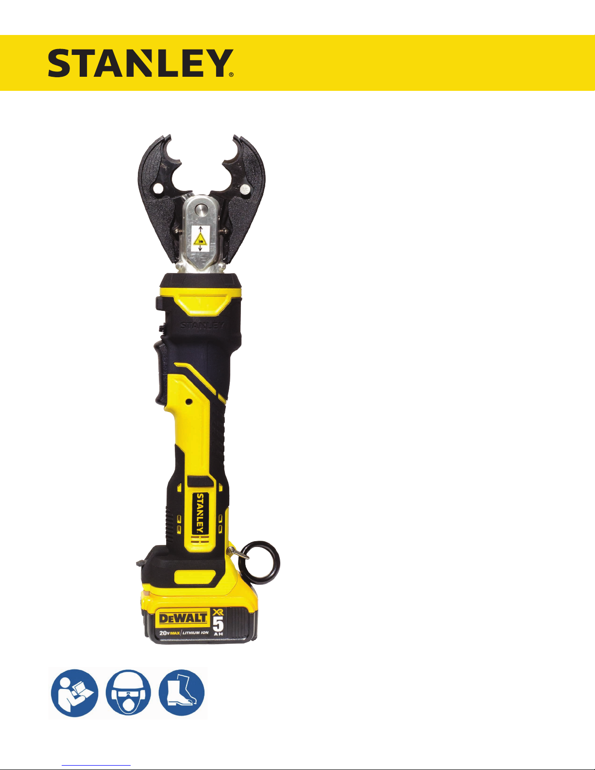
IBC600
6-TON IN-LINE
CRIMPING TOOL
USER MANUAL
Safety, Operation and Maintenance
© 2017 STANLEY Black & Decker, Inc.
New Britain, CT 06053
U.S.A.
81140 1/2018 Ver. 2
Page 2

Page 3
TABLE OF CONTENTS
SAFETY SYMBOLS ...............................................................................................................................................4
SAFETY PRECAUTIONS .......................................................................................................................................5
TOOL ANATOMY ....................................................................................................................................................6
SPECIFICATIONS & ACCESSORIES ....................................................................................................................7
OPERATION ...........................................................................................................................................................8
STANLEY CRIMP SOFTWARE ..............................................................................................................................11
TROUBLESHOOTING ...........................................................................................................................................16
IBC600 PARTS ILLUSTRATION ............................................................................................................................17
IBC600 PARTS LIST ..............................................................................................................................................18
IBC600 HYDRAULIC BODY ILLUSTRATION ........................................................................................................19
IBC600 HEAD UNIT ILLUSTRATION .....................................................................................................................20
92821 CRIMPING JAW ILLUSTRATION................................................................................................................21
92822 CRIMPING JAW ILLUSTRATION................................................................................................................22
92823 CRIMPING JAW ILLUSTRATION................................................................................................................23
To ll out a product warranty validation form and for information on your warranty,
visit www.stanleyinfrastructure.com and select the Company tab > Warranty.
Note: The warranty validation record must be submitted to validate the warranty.
SERVICING: This manual contains safety, operation and routine maintenance instructions. STANLEY Infrastructure
recommends that servicing of hydraulic tools, other than routine maintenance, must be performed by an authorized
and certied dealer. Please read the following warning.
SERIOUS INJURY OR DEATH COULD RESULT FROM THE IMPROPER REPAIR OR
SERVICE OF THIS TOOL.
REPAIRS AND / OR SERVICE TO THIS TOOL MUST ONLY BE DONE BY AN
AUTHORIZED AND CERTIFIED DEALER.
For the nearest certied dealer, call STANLEY Infrastructure at (503) 659-5660 and ask for a Customer Service Representative.
IBC600 User Manual ◄ 3
Page 4

SAFETY SYMBOLS
Safety symbols and signal words, as shown below, are used to emphasize all operator, maintenance and repair
actions which, if not strictly followed, could result in a life-threatening situation, bodily injury or damage to equipment.
This is the safety alert symbol. It is used to alert you to potential personal injury
hazards. Obey all safety messages that follow this symbol to avoid possible
injury or death.
This safety alert and signal word indicates an imminently hazardous situation
which, if not avoided, will result in death or serious injury.
This safety alert and signal word indicates a potentially hazardous situation
which, if not avoided, could result in death or serious injury.
This safety alert and signal word indicates a potentially hazardous situation
which, if not avoided, could result in death or serious injury.
This signal word indicates a potentially hazardous situation which, if not avoided,
may result in property damage.
This signal word indicates a situation which, if not avoided, will result in damage
to the equipment.
This signal word indicates a situation which, if not avoided, may result in damage
to the equipment.
Always observe safety symbols. They are included for your safety and for the protection of the tool.
LOCAL SAFETY REGULATIONS
Enter any local safety regulations here. Keep these instructions in an area accessible to the operator and
maintenance personnel.
4 ► IBC600 User Manual
Page 5

SAFETY PRECAUTIONS
Tool operators must comply with precautions given in this
manual and on the stickers attached to the tool.
These precautions are given for your safety. Review them
carefully before operating the tool.
Supervising personnel should develop additional precautions
relating to the specic work area and local safety regulations.
Place the added precautions in the space provided on page
4.
The IBC600 6-Ton In-line Crimping Tool will provide safe
and dependable service if operated in accordance with
the instructions in this manual. Read and understand this
manual and stickers attached to the tool before operation.
Failure could result in injury or tool damage.
• Use the tool in a work area without bystanders.
• Do not operate the tool unless thoroughly trained or
under the supervision of an instructor. Establish a training
program for all operators to ensure safe operation.
• Always wear safety equipment such as eye protection,
ear protection, head protection and safety shoes at all
times when operating the tool. Use gloves if necessary.
• The operator must be familiar with all prohibited work
areas such as excessive slopes and dangerous terrain
conditions. Ensure that your footing is rm and you are
in balance at all times.
• Do not inspect, clean or replace tool jaws while the
battery is connected. Accidental engagement of the tool
can cause serious injury.
• Do not operate a damaged, improperly adjusted or
incompletely assembled tool.
• Never wear loose clothing that can become entangled in
the working parts of the tool.
• Keep all parts of your body away from pinch points. Long
hair or loose clothing can become drawn into the tool.
• To avoid personal injury or equipment damage, all tool
repair, maintenance and service must be performed by
an authorized service center.
• Never use the tool in the vicinity of ammable materials
or gases.
• Do not use the tool or charge the tool battery in an
explosive atmosphere.
• Cutting or severing of body parts is possible if proper
procedures are not followed.
• Do not use the tool, battery or battery charger for
purposes other than what is described in this manual.
• Always keep critical tool markings, such as labels
and warning stickers, legible. Contact STANLEY for
replacement labels.
• Do not use the tool while under the inuence of drugs
or alcohol.
• Do not use accessories or attachments other than those
recommended by STANLEY.
BATTERIES
• Only charge batteries using a STANLEY recommended
battery charger.
• Do not store batteries with metal objects, such as coins,
nails or keys. Fire can result if battery terminals are
shorted.
• Do not charge a damaged battery. Recycle and replace
damaged batteries with batteries recommended by
STANLEY.
• Do not incinerate or dispose of batteries in the garbage.
Recycle the batteries.
• Do not expose the battery to temperatures over 265°F.
Batteries may explode at high temperatures.
• Leakage of liquid from the battery may occur under
extreme use or high temperatures. If battery liquid gets
on your skin:
1. Wash quickly with soap and water.
2. If the liquid gets in your eyes, ush your eyes
with clean water for 10 minutes. Seek medical
attention immediately.
• Never open the battery.
BATTERY CHARGER
• Do not use the battery charger if the cord is damaged.
• Do not place the charger, or set items on or near the
charger, in such a way as to block airow to the charger.
• Do not use the charger with an extension cord unless
absolutely necessary. Use a cord with the proper wire
size for its length, as described in Table 1.
Length of Cord (Feet) 25 50 100 150
Wire Size (AWG) 18 18 18 16
Table 1: Extension Cord Wire Size
• Do not open the charger or attempt to modify it in any
way.
• Disconnect the charger from power before attempting
to clean it.
• Do not connect the charger to a transformer or engine
generator.
IBC600 User Manual ◄ 5
Page 6

TOOL ANATOMY
WHAT IS THE IBC600?
The IBC600 is a battery powered 6-Ton in-line crimping tool with interchangeable crimping jaws. IBC600 is capable of
crimping copper and aluminum connectors to 500 MCM and HTAPS to 4/0-4/0. The InteLED gives real time feedback
to the operator and alerts them to a possible bad crimp.
Crimping Jaws
Crushing Risk
Decal
DO NOT put ngers, hands or other body parts between
the jaws. Serious injury will result!
InteLED
Trigger Lock
Trigger
Pressure Release
Pin Lock
Tool Identication &
Warning Decal
USB Port
6 ► IBC600 User Manual
Battery
Page 7

SPECIFICATIONS & ACCESSORIES
SPECIFICATIONS
Crimping Force .....................................................................................................................................6 Tons (53 kN)
Tool Cycle Time ........................................................................................................................................4.5 seconds
Crimping Capacity ...................................................................................Copper/Aluminum connectors to 500 MCM
HTAPS to 4/0-4/0
Battery Type ........................................................................................DeWalt 20V Max (2 Amp/hour or 5 Amp/hour)
Estimated Crimps per Charge ........................................................................... 200 (2 Amp/hour), 450 (5 Amp/hour)
Tool Weight
with 2 Amp/hour battery ............................................................................................................................7.15 Lbs.
with 5 Amp/hour battery ............................................................................................................................7.70 Lbs.
Tool Length ..................................................................................................................18.8 Inches (2 Amp/hour batt.)
19.6 Inches (5 Amp/hour batt.)
Maintenance Interval ..................................................................................................................Every 30,000 Cycles
ACCESSORIES
D3/O Jaw ........................................................................................................................................................... 92821
(Accepts standard “W” dies)
D3/BG Jaw ........................................................................................................................................................92822
(Accepts standard “W” dies)
Kearney/BG Jaw................................................................................................................................................92823
(Accepts Kearney and “W” dies)
2 Amp/hour DeWalt 20V Max Battery ............................................................................................................ DCB203
5 Amp/hour DeWalt 20V Max Battery ............................................................................................................ DCB205
5 Amp/hour DeWalt 20V Max Battery 2-pack ............................................................................................. DCB205-2
120V AC Charger ...........................................................................................................................................DCB115
12V DC Charger .............................................................................................................................................DCB119
Note: Only use battery chargers recommended by STANLEY.
Bucket Bag ......................................................................................................................................................... BB01
IBC600 User Manual ◄ 7
Page 8
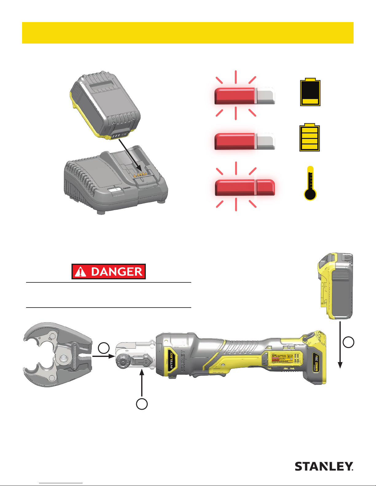
CHARGE BATTERY
OPERATION
Battery Charging
Battery Charged
Hot/Cold Delay
INSTALL CRIMPING JAW AND BATTERY
DO NOT install or change crimping jaws while the battery
is connected to the tool. Disconnect the battery BEFORE
installing or changing crimping jaws.
2
1
3
1. Pull back the pin lock to eject the jaw pin.
2. Insert the crimping jaw and lock the jaw pin.
8 ► IBC600 User Manual
3. Insert the battery pack.
Page 9

OPERATION
2
CRIMPING
1
1. Set the Trigger Lock
Set the trigger lock BEFORE attaching
dies to the jaw!
2. Clip the die onto the Crimping Jaw.
DO NOT crimp live cables! IBC600 is
NOT a live-line tool!
3. Release the Trigger Lock.
4. Press and hold the trigger until the tool has nished.
4 5
Figure 1: Lock the Trigger
5. Press and hold the pressure release.
Note: Release the trigger to immediately stop the
tool. Press the pressure release at any time to open
the jaws.
InteLED System
The InteLED system shows the status of the crimp. The light ring will shine different colors depending on the status
of the crimp.
InteLED Light Ring
InteLED Meaning
Crimping. InteLED will stay
White
Green The crimp is good.
Red
lit for 30 seconds after a
crimp is complete.
IBC600 did not reach full
pressure. Crimp again.
IBC600 User Manual ◄ 9
Page 10

OPERATION
CHECKING BATTERY CHARGE
Battery Check Button
SECURE THE JAWS INTO PLACE (OPTIONAL)
75 - 100% Charged
51 - 74% Charged
Less than 50% Charged
Charge Battery
Jaw Coupling
IBC600 jaws can be secured into place by inserting a
pin and set screw (supplied) into the jaw coupling. This
will prevent the user from unlocking the jaw pin and
removing the jaws.
1. Set the trigger lock and insert the jaws.
2. Lock the jaw pin into place.
3. Insert the pin and set screw to lock the jaw pin.
3
1
2
10 ► IBC600 User Manual
Page 11

OPERATION
STANLEY CRIMP SOFTWARE
STANLEY Crimp software provides valuable data about
each crimp. It is also required to update the tool rmware.
INSTALLATION
1. Download the STANLEY Crimp software from the
STANLEY Infrastructure website.
www.stanleyinfrastructure.com/products/cordless-td
Note: STANLEY Crimp software requires a minimum
of Windows XP SP3 running with administrator
rights.
2. Follow the prompts to complete installation.
3. Connect IBC600 to a PC using a micro USB cable.
Note: InteLED will shine blue when connected.
FIRST RUN
1. Run the software using the STANLEY Crimp
software icon on your Windows desktop.
2. You will be prompted to register your software. Left
click the “User Registration” button.
3. Fill out the registration form and click the “Register”
button.
IBC600 USB Connection
USER SELECTION
1. Click the “New User” button.
2. Enter the required user information and click “Create”.
3. Select a user and click “OK”.
IBC600 User Manual ◄ 11
Page 12

TOOL INFORMATION
OPERATION
1 2
The Tool Information tab displays important data about the IBC600.
1. Displays the product type, serial number and rmware version of the tool.
2. Basic data relating to the life and service interval of the tool.
TOOL USAGE DATA
1
3
2
12 ► IBC600 User Manual
Page 13

OPERATION
The Tool Usage Data tab displays information about individual tool cycles.
1. Displays the total number of tool cycles, as well as completed and non-complete cycles.
2. The data log shows each cycle, up to 250,000 cycles. Each entry into the log includes;
• Date and time of each crimp
• If the cycle completed successfully
• Amperage and Voltage of the tool during each crimp
• Tool temperature at the end of each crimp
3. Data log sorting lters. Allows you to sort the crimp data in the data log.
WORKSITE REPORTS
1
IBC600 User Manual ◄ 13
Page 14

OPERATION
The Worksite Reports tab allows you to group data log entries into a complete tool cycle report.
2
4
3
1. Click “Create Report”.
2. Select the date range of the job you are reporting.
3. Select the crimp cycles you want to include in the report.
4. Select a user and a worksite.
Note: If this is the rst time using the software, press the “Worksites” button to create a worksite.
5. Enter notes about the job in the Remarks eld.
6. Click “OK” when nished.
5
7
7. Select a report from the reports list.
8. Click “Print Report to PDF” to export the Worksite Report.
14 ► IBC600 User Manual
Page 15

AVAILABLE UPDATES
OPERATION
1
2
The Available Updates tab will allow you to update the tool rmware and update STANLEY Crimp software.
1. Tool Firmware Update button. When clicked, this will begin to tool rmware update process. Do not unplug the
tool during this process.
2. Software Update button. When clicked, this will update the STANLEY Crimp software, if an update is available.
IBC600 User Manual ◄ 15
Page 16

TROUBLESHOOTING
Problem Solution
I can’t install the crimping jaw / The crimping jaw
doesn’t t into the tool body.
Press and hold the pressure release to fully retract the
piston. Insert the jaw into the tool body.
The jaw pin won’t t through the hole in the crimping
jaw.
The jaw pin wont spring back, even though I am pulling
back on the pin lock.
The tool won’t crimp when I press the trigger. Ensure the battery is charged. Disengage the trigger
The InteLED ashes yellow when I activate the tool. The maintenance interval is about to elapse. Have the
The tool repeatedly gives me bad crimps / The InteLED
ashes red after every crimp.
The tool will not release pressure when the pressure
release is held.
The tool is leaking hydraulic oil. Have the tool serviced immediately.
The tool cannot connect to STANLEY Crimp software. Ensure the tool is connected to the computer via the
The tool is not saving crimp data. Have the tool serviced as soon as possible.
Remove the crimping jaw. Ensure the two halves of the
crimping jaw are aligned.
Ensure that the jaw locking hardware is removed (see
page 10). Press and hold the pressure release to
fully retract the piston. Pull back on the pin lock to eject
the jaw pin.
lock.
tool serviced as soon as possible.
Ensure the battery is fully charged. Ensure the
crimping jaw is properly installed and the die is
properly attached. If problem persists, have the tool
serviced as soon as possible.
Have the tool serviced immediately.
USB port and that InteLED is blue. Your computer
may be downloading USB drivers. Check the Windows
system tray for download progress.
16 ► IBC600 User Manual
Page 17

7
24
IBC600 PARTS ILLUSTRATION
10
44
152
86
78
67
68
50
86
69
76
153
23
136
106
75
81
110
78
47
108
105
75
44
110
157
63
52
34
63
71
72
50
99
40
41
42
165
10
100
4
111
156
164
166
7
IBC600 User Manual ◄ 17
Page 18

IBC600 PARTS LIST
ITEM P/N QTY DESCRIPTION
4 62412DUB 1 Compression Spring
23 77058 1 Shackle (Torque to 2
Nm)
24 91410 1 USB Cover
34 91585 1 Oil Tank
40 91586 1 Oil Tank Plug
41 ZBINA405 1 Magnet Pin
42 91616 1 Metal Clamp
44 91611 1 Housing Set
47 J4450300X70 1 O-Ring 44.5 x 3
50 92878 1 Electronic Device
52 AIG1.5x7.8BR 1 Calibrated Pin
63 91617 2 Metal Clamp
67 AAIN20 1 Circlip
68 JSR122004 2 Lip Seal
69 JBS04.5 2 Sealing Washer
75 VAV03HC006 2 Screw
76 VAV04CB006 4 Screw (Torque to 2 Nm)
78 VAV04FH006 6 Screw (Torque to 2 Nm)
81 VAV3.5TC014ZN 7 Screw
86 91623 2 Membrane Support
100 62411DUB 1 Compression Spring
103 77070 1 Cam Holder
105 91647 1 STANLEY Logo Decal
106 91648 1 IBC600 Decal
107 91634 1 “Powered by DeWalt”
Right Decal
108 91635 1 “Powered by DeWalt”
Left Decal
109 91637 1 INTELED Left Decal
110 91636 1 INTELED Right Decal
111 77067 1 Cam
113 RBAM12262 1 Pin Stop
136 91465 1 Strap Ring
152 92833 1 Motor and Gearbox
Assembly
ITEM P/N QTY DESCRIPTION
153 See page 19 1 Hydraulic Body
Assembly
156 See page 20 1 Head Unit
157 92877 1 Outer Trigger Assembly
164 70884DUB 1 Roller Assembly
165 75147 1 Piston
166 91603 1 Guiding Ring
(Torque to 25 Nm)
18 ► IBC600 User Manual
Page 19

IBC600 HYDRAULIC BODY ILLUSTRATION
65
25
18
160
27
162
16
48
52
40
163
254
55
52
162
ITEM P/N QTY DESCRIPTION
161
35
56
16 31318DUB 1 Spring
18 77286 2 Cam Roller
25 77065 1 Cam Box
27 91606 1 Release Lever
35 77086 2 Spring
40 91584 1 Hydraulic Body
48 77504 1 Spring
52 AIG2.5X13.8BR 2 Pin
55 AIG4X13.8BP 1 Calibrated Pin
56 AIG4X29.8BP 1 Calibrated Pin
65 J3100200 1 O-Ring 31 x 2
160 77805-01 1 Delivery Valve Unit
161 77076 1 Cross Head
162 77837 1 Pressure release valve
(Torque to 6 Nm)
163 77806-01 1 Succion Valve Unit
(Torque to 12 Nm)
254 92875-11 1 Valve Unit
(Torque to 12 Nm)
IBC600 User Manual ◄ 19
Page 20

IBC600 HEAD UNIT ILLUSTRATION
8
13
15
9
12
10
11
57
8
2
4
15
3
14
6
1
ITEM P/N QTY DESCRIPTION
1 77035-02 1 Toothed Wheel
2 77394 1 Axis for jaws set
3 78476-01 1 Pull Tab
4 78586 1 Spring
5 84015DUB 1 Spring
6 91437 1 Plug
7 91440 1 Spacer Tube
8 91591 2 Half Flange
9 AIG1.5X7.8BR 2 Calibrated pin
10 AIG3x12.8BP 1 Calibrated Pin
11 AIG3.5x23.8BR 2 Calibrated Pin
12 VAV04BT006FF 1 Screw
13 VAV04EB010 1 Screw
14 VAV04CB015 1 Screw
15 VAV04HC010 4 Screw
20 ► IBC600 User Manual
Page 21

92821 CRIMPING JAW ILLUSTRATION
1
2
3
1
2
6
7
ITEM P/N QTY DESCRIPTION
1 77387 2 Machined Jaw
2 91622 2 Shell
3 62270DUB 2 Jaw Open Spring
4 91589 2 Push Rod
5 91588 2 Spring
6 91590 2 Push Rod Screw
7 91621 2 Spring Pin
5
4
IBC600 User Manual ◄ 21
Page 22

92822 CRIMPING JAW ILLUSTRATION
1
2
3
1
2
6
7
ITEM P/N QTY DESCRIPTION
1 91455 2 Machined Jaw
2 91622 2 Shell
3 62270DUB 2 Jaw Open Spring
4 91589 2 Push Rod
5 91588 2 Spring
6 91590 2 Push Rod Screw
7 91621 2 Spring Pin
5
4
22 ► IBC600 User Manual
Page 23

92823 CRIMPING JAW ILLUSTRATION
1
2
3
1
2
6
5
4
7
10
ITEM P/N QTY DESCRIPTION
1 77389 2 Machined Jaw
2 91622 2 Shell
3 62270DUB 2 Jaw Open Spring
4 77418 2 Spring Cap
5 31224DUB 2 Spring
6 77416 2 Axis for Kearney Die
7 91590 2 Push Rod Screw
8 91588 2 Spring
9 91589 2 Push Rod
10 91621 2 Spring Pin
11 77417 2 Pin for Die Lock
11
8
9
IBC600 User Manual ◄ 23
Page 24

STANLEY Infrastructure
6430 SE Lake Road
Portland, Oregon 97222 USA
(503) 659-5660 / Fax (503) 652-1780
www.stanleyinfrastructure.com
 Loading...