

Page 1
WARNING
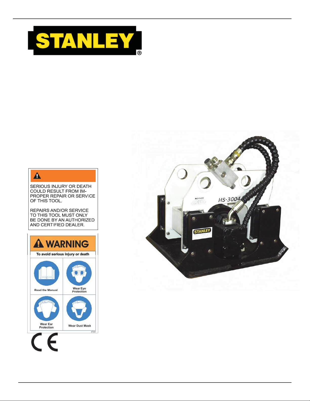
HS3000
MOUNTED
HYDRAULIC COMPACTOR
©
Stanley Hydraulic Tools 2005
SVCE/MAINT USA / CE
Printed in U.S.A.
65764 8/2005 ver 3
SAFETY, OPERATION AND MAINTENANCE
SERVICE MANUAL
Stanley Hydraulic Tools
3810 SE Naef Road
Milwaukie OR 97267-5698
503-659-5660
FAX 503-652-1780
www.stanley-hydraulic-tools.com
Page 2

Page 3

TABLE OF CONTENTS
CERTIFICATE OF CONFORMITY ................................................................................................................................................. 4
SAFETY SYMBOLS ....................................................................................................................................................................... 5
SAFETY PRECAUTIONS .............................................................................................................................................................. 6
TOOL STICKERS & TAGS ............................................................................................................................................................ 7
OPERATION .................................................................................................................................................................................. 8
PREOPERATION PROCEDURES ............................................................................................................................................. 8
DAILY MAINTENANCE CHECKS ............................................................................................................................................. 8
PRE-INSTALLATION INSTRUCTIONS ...................................................................................................................................... 8
LOW-TEMPERATURE WARM-UP PROCEDURE ..................................................................................................................... 8
GENERAL INSTRUCTIONS ...................................................................................................................................................... 9
COMPACTION ........................................................................................................................................................................... 9
GENERAL .................................................................................................................................................................................. 9
SLOPE TECHNIQUE ................................................................................................................................................................. 9
SOIL TESTING ........................................................................................................................................................................... 9
DRIVING .................................................................................................................................................................................... 9
TROUBLESHOOTING ..................................................................................................................................................................11
FLOW TEST PROCEDURES ...................................................................................................................................................... 12
DEFINITION OF TERMS ............................................................................................................................................................. 14
SPECIFICATIONS ....................................................................................................................................................................... 15
SERVICE ..................................................................................................................................................................................... 17
DISASSEMBLY ...................................................................................................................................................................... 17
PARTS INSPECTION ............................................................................................................................................................. 17
SEALS .................................................................................................................................................................................... 17
BASEPLATE ........................................................................................................................................................................... 17
BEARING CARRIERS ............................................................................................................................................................ 17
BEARINGS ............................................................................................................................................................................. 17
SHOCK MOUNTS .................................................................................................................................................................. 18
HOSE AND FITTINGS ............................................................................................................................................................ 18
ASSEMBLY ............................................................................................................................................................................ 18
TORQUE SPECIFICATIONS ................................................................................................................................................. 18
PRIOR TO ASSEMBLY .......................................................................................................................................................... 18
ASSEMBLY PROCEDURE .................................................................................................................................................... 18
PARTS ILLUSTRATION .............................................................................................................................................................. 20
PARTS LIST ................................................................................................................................................................................. 21
WARRANTY ................................................................................................................................................................................. 22
SERVICING THE STANLEY HYDRAULIC compactor. This manual contains safety, operation, and routine
maintenance instructions. Servicing of hydraulic tools, other than routine maintenance, must be performed by an authorized and certifi ed dealer. Please read the following warning.
WARNING
SERIOUS INJURY OR DEATH COULD RESULT FROM THE IMPROPER REPAIR OR SERVICE OF THIS TOOL.
REPAIRS AND / OR SERVICE TO THIS TOOL MUST ONLY BE
DONE BY AN AUTHORIZED AND CERTIFIED DEALER.
For the nearest authorized and certifi ed dealer, call Stanley Hydraulic Tools at the number listed on the
cover of this manual and ask for a Customer Service Representative.
3
Page 4

CERTIFICATE OF CONFORMITY
Hydraulic Tools
______________________________________________________________________
I, the undersigned:
Hereby certify that the construction plant or equipment specified hereunder:
1. Manufacturer: Stanley Hydraulic Tools, 3810 Naef Road, Milwaukie, Oregon USA
2. Representative in the Union: Stanley Svenska AB, Box 9054, 400 92 Göteborg, SWEDEN
3. Category: Hydraulic Powered Compaction Machine
4. Make: Stanley Hydraulic Tools
5. Type: HS3000
6. Type serial number of equipment: ALL
Burrows, James O.
Surname and First names
7. Year of manufacture: Beginning 2002
Has been manufactured in conformity with the provisions of the Machinery Directive 98/37/EC
Standard applied: EN 292-1, 292-2
We also declare that it meets the specification of Noise Directive 2000/14/EC, measured in accordance to
the Conformity Evaluation Method set out in Annex VI para. 5 and evaluated during production as in Annex
VI para. 6, 2
8. Noise related value: 7.8 kW
9. Measured sound power on equipment representative of this type: 105 LwA
10. Guaranteed sound power level for this equipment: 108 LwA
11. Notified body for EC directive 2000/14/EC: 0404 SMP Svensk Maskinprovning AB
754 50 Uppsala, SWEDEN
12. Special Provisions: None
Issued at Stanley Hydraulic Tools, Milwaukie, Oregon USA
Date 9/30/02
nd
procedure.
Fyrisborgsgatan 3
Signature
Position: Engineering Manager
P/N 52647 Rev. 01 9/30/02
4
Page 5

SAFETY SYMBOLS
Safety symbols and signal words, as shown below, are used to emphasize all operator, maintenance and repair
actions which, if not strictly followed, could result in a life-threatening situation, bodily injury or damage to equipment.
This is the safety alert symbol. It is used to alert you to potential personal
injury hazards. Obey all safety messages that follow this symbol to avoid
possible injury or death.
DANGER
WARNING
CAUTION
NOTICE
IMPORTANT
Always observe safety symbols. They are included for your safety and for the protection of the tool.
This safety alert and signal word indicate an imminently hazardous situation which, if not avoided, will result in death or serious injury.
This safety alert and signal word indicate a potentially hazardous situation
which, if not avoided, could result in death or serious injury.
This safety alert and signal word indicate a potentially hazardous situation
which, if not avoided, may result in minor or moderate injury.
This signal word indicates a potentially hazardous situation which, if not
avoided, may result in property damage.
This signal word indicates a situation which, if not avoided, will result in
damage to the equipment.
This signal word indicates a situation which, if not avoided, may result in
damage to the equipment.
LOCAL SAFETY REGULATIONS
Enter any local safety regulations here. Keep these instructions in an area accessible to the operator and maintenance personnel.
5
Page 6

SAFETY PRECAUTIONS
Tool operators and maintenance personnel must always comply with the safety
precautions given in this manual and on the stickers and tags attached to the tool
and hose.
These safety precautions are given for your safety. Review them carefully before
operating the tool and before performing general maintenance or repairs.
Supervising personnel should develop additional precautions relating to the specifi c
work area and local safety regulations. If so, place the added precautions in the
space provided in this manual.
The HS3003/3004 Mounted Hydraulic Compactor’s will provide safe and dependable service if operated in accordance with the instructions given in this manual.
Read and understand this manual and any stickers and tags attached to the tool
and hoses before operation. Failure to do so could result in personal injury or
equipment damage.
Check the rule and regulations at your location. The rules might include an employer's work safety program. Regulations may identify hazards such as working
around utility supply lines or hazardous slopes.
BE THOROUGHLY TRAINED BEFORE OPERATING THE UNIT ALONE
• Operator training must start in an area without bystanders and use all the controls until he/she can control the machine
fully under the conditions of the work area.
• When learning to operate a machine, do so at a slow pace.
KNOW THE WORK CONDITIONS
• The operator must know any prohibited uses or work areas for the machine. For example, excessive slopes and poor
or dangerous terrain conditions must be avoided.
OBEY SAFETY RULES
• Replace all faulty or leaking hydraulic hoses or fi ttings before further operation.
• Always operate the compactor with backhoe outriggers fi rmly on the surface. The compactor weighs more than the
bucket. Position the compactor with caution.
• Travel with the compactor in full tuck (transport) position only.
• Never operate with any person near the compactor or between the compactor and operator.
• Operate the compactor in properly shored trenches and excavations. Do not allow personnel to work in the excavation
near compactor operation.
• Make sure all controls (levers and pedals) are in the NEUTRAL position before starting the carrier.
• Wear safety eye protection, hard hat, and safety foot protection while operating the compactor.
• Operate the carrier or compactor from the operator's seat ONLY. Make sure the seat belt is securely fastened before
activating any controls.
• Make certain that no other personnel are within the arc prescribed by the movement of the stabilizers, front bucket or
backhoe boom.
• Keep hands and feet on the controls at all times when the machine is running.
• Before leaving the operator's seat, always lower the loader arms and the backhoe boom.
• NEVER leave the machine with the engine running. ALWAYS ENGAGE THE PARKING BRAKE.
• Stop the engine before attempting to make any repairs or adjustments to either the carrier or compactor.
• To avoid personal injury or equipment damage, all tool repair, maintenance and service must only be performed by
authorized and properly trained personnel.
6
Page 7
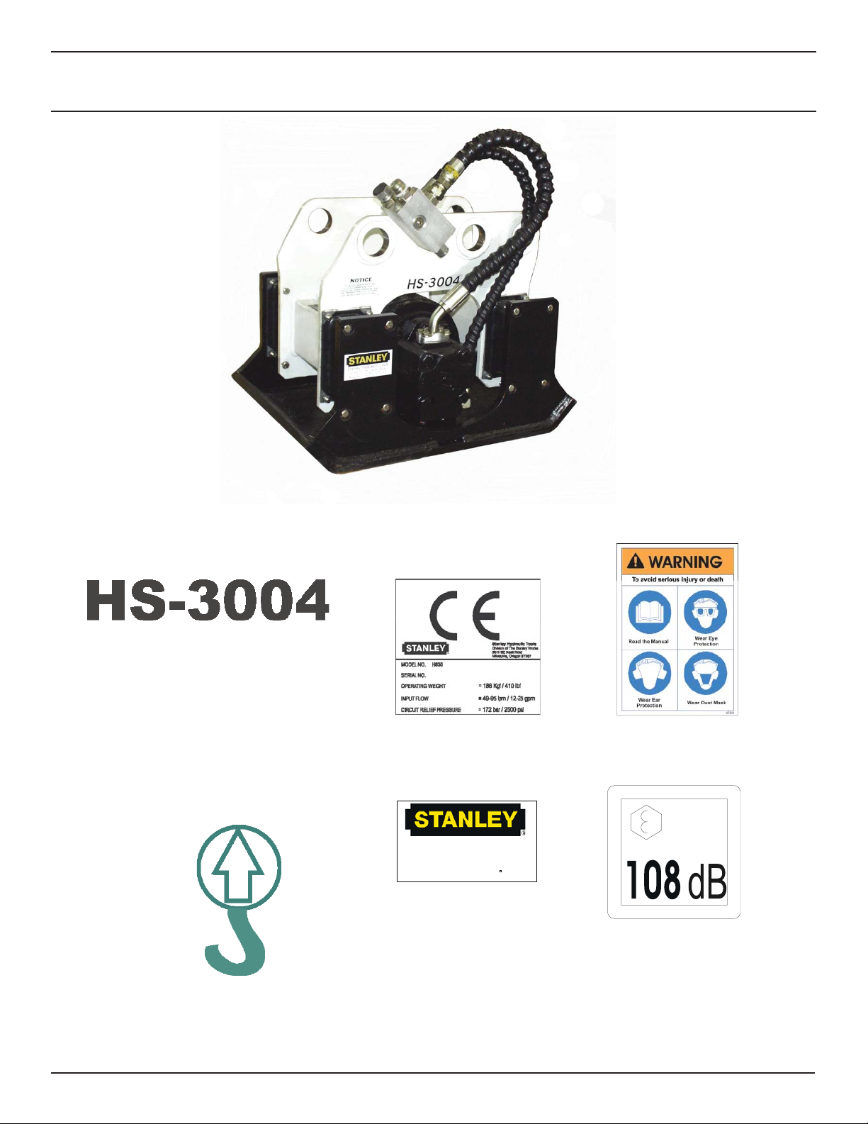
TOOL STICKERS & TAGS
18968
Model Decal
47352
Lift Point Decal
58887
GPM Decal
Stanley Hydraulic tools
Division of the Stanley Works
3810 SE Naef Road
Milwaukie, OR 97267
05152
Stanley Decal
47351
Composit Warning
Lwa
58602
Sound Power Decal
7
Page 8

OPERATION
PREOPERATION PROCEDURES
DAILY MAINTENANCE CHECKS
Check for loose or missing fasteners. Tighten or replace
as needed. See Torque Specifi cations in the ASSEMBLY
section of this manual.
Check to be certain that the fl ow control valve on the carrier
is set to the proper fl ow for the compactor. See the SPECIFICATIONS section of this manual.
Check shock mounts for cracks or tears. Rotate shock
mounts 180° when fatigue tears begin to show at top outer
crease of the shock mount. This will prolong the life of the
shock mount.
Check for abrasion and hydraulic leaks at fi ttings and
hoses. Replace defective hoses and fi ttings. Adjust hoses
and tighten fi ttings so the hoses do not defl ect into contact
with structure during use.
WARNING
Be sure the fl uid and fi lter in the hydraulic system are
clean.
When tightening pipe threads, be careful that any sealant used (Tefl on
system. Foreign matter introduced into the system may
damage hydraulic valves, motors and pumps.
Follow instructions to install the Stanley priority valve in the
carrier hydraulic system. the warranty is in effect only if the
valve and compactor are installed as outlined in the valve
kit installation instructions. Major modifi cations or equipment substitution will cause the warranty to be void unless
prior engineering approval has been granted by Stanley
Hydraulic Tools.
The Stanley priority valve is a metering (to the hydraulic
tool) pressure compensating valve that controls the fl ow to
the attachment and gives the primary system (i.e. backhoe
functions) full operating pressure. Diverter valves or simple
fl ow control valves will not perform all of these required
functions.
Note:
On carriers where priority valves are not used, check
with your local Stanley distributor for an adapter kit to
equip your carrier for a specifi c model of compactor.
®
tape, etc.) does not enter the hydraulic
DO NOT USE BARE HANDS TO CHECK OR
SEARCH FOR HYDRAULIC LEAKS AROUND
HOSES AND FITTINGS. PINHOLE LEAKS CAN
PENETRATE THE SKIN. TO INSPECT FOR
LEAKS, DEPRESSURIZE THE SYSTEM, CLEAN
AROUND SUSPECTED AREA, REPRESSURIZE
THE SYSTEM, AND VISUALLY CHECK FOR
LEAKS.
Lubricate bearings with two pumps of grease every 40
hours of operation. A greasing location is provided in both
bearing carriers.
Inspect pins and bushings for correct fi t and lubrication.
Check level of hydraulic reservoir on carrier.
Make certain that quick couplers are fully engaged and leak
free.
PRE-INSTALLATION INSTRUCTIONS
LOW-TEMPERATURE WARM-UP PROCEDURE
When the weather gets cold, the shock mounts on compactors can become stiff. In severe weather, where the
ambient temperature is below freezing for extended periods, shock mounts can even become brittle. Therefore, it
is necessary to warm the shock mounts prior to using the
compactor. To warm the shock mounts follow these steps:
1. After starting the carrier, warm up the system until hydraulic lines are warm to the touch.
2. With the carrier at idle, place the compactor fl at on the
ground, and using a slight down pressure to keep the compactor in place, turn the compactor on. DO NOT place a
load on the compactor during this procedure.
3. When the ambient temperature is below freezing, the
compactor should be operated on the ground with a slight
down pressure (no load) for at least one minute before put-
ting it to work.
Test the carrier hydraulic system to verify that the system
is operating at the manufacturer's specifi ed capacity and
pressure ratings.
8
Page 9

OPERATION
IMPORTANT
DO NOT SUSPEND THE COMPACTOR IN THE AIR
DURING THE WARM-UP PROCEDURE.
THE COMPACTOR MUST BE PLACED FLAT ON
THE GROUND WITH A VERY SLIGHT DOWN
PRESSURE TO KEEP IT IN PLACE. WHEN AMBIENT TEMPERATURES ARE BELOW FREEZING,
SUSPENDING THE COMPACTOR IN THE AIR
WITHOUT FIRST WARMING IT UP MAY CAUSE
THE SHOCK MOUNTS TO CRACK.
FAILURE TO FOLLOW THESE PROCEDURES
WILL VOID COMPACTOR SHOCK MOUNT WAR-
RANTY.
With a standard baseplate, the compactor is held with
full down pressure for no more than 5-10 seconds. The
application pattern should always begin next to a bank or
footing and at the previously compacted area. When the
maximum attainable density for that particular soil condition
is reached, a slight increase in vibration will be felt by the
operator. This increase in vibration is in no way harmful to
the tractor, and indicates that the soil will not compress any
further. In fact, additional time in that location may actually
loosen the soil previously compacted.
Work as much area as possible from one position and
overlap each compacted section slightly. The vibration
frequency has been chosen to give maximum effi ciency in
granular soils using lifts of 2 to 4 feet. The closer the width
of the trench is to the width of the compactor, the higher the
delivered compactive effort.
GENERAL INSTRUCTIONS
The compactor is a device that uses available force to
the best advantage. The DYNAMIC FORCE of the mass
weight assembly, turning at a high rpm, produces a vibratory force, and with controlled placement, an impact force.
The DOWN PRESSURE of the carrier on the compactor
gives a high static pressure which assists in the compaction or driving. The vibration frequency is controlled by the
hydraulic fl ow input to the compactor and is optimized for
use in granular soils. The rate and density of compaction
depends on such factors as moisture content of the soil,
condition of the compactor and carrier, and the skill of the
operator.
NOTICE
Effi cient compactor performance is directly related to the fl ow rate specifi ed. A higher fl ow rate
does not improve performance. It results in fl uid
overheating, and contributes to early bearing
failure. A lower fl ow rate causes reduced compaction performance.
The HS3000 Compactor delivers up to 3,400 lbs/1,542 kg
of vibratory force. Its base plate covers a 17.5 x 20 in./44
x 51 cm area. It comes standard with a fl ow control to prevent overspeeding.
COMPACTION
It is necessary to turn the compactor OFF when being
transported or sitting idle. Should the running compactor
be placed on a hard surface without down pressure, the
unit and the carrier will vibrate excessively. Down pressure
transmits the vibration to the soil; neutral pressure will rattle
the whole carrier assembly.
SLOPE TECHNIQUE
This method of compaction is of primary interest to a
pipeline contractor seeking high production and effi cient
equipment utilization. The fi ll material is placed at one end
of the trench and allowed to seek its own angle of repose.
Compaction is begun on this angle above, but still near, the
top of the pipe. All fi ll material is backfi lled to this angle and
the compactor is worked up and down the slope. Backfi lling, compaction, and resurfacing can be done very shortly
after the pipe is in place.
SOIL TESTING
Compaction density specifi cations are based on soil samples of a set moisture content and soil composition. Changing weather conditions, for example, can alter the moisture
content of the fi ll being used, and may make meeting the
specifi cations impossible. It is imperative that frequent and
reliable tests be conducted during application of the compactor to determine the maximum lift that can be used and
still provide the required density. It is important that lifts in
excess of the established test results NOT be used if the
required density is to be achieved and maintained.
GENERAL
The following instructions are very important to the proper
performance of the compactor and the attainment of the
specifi ed compaction density.
DRIVING
Many driving jobs can be done with the compactor. Timber
sheeting, steel and aluminum sheeting, H and I-beams,
soldier piles and guard rail posts. The compactor will drive
9
Page 10

OPERATION
these materials in most soil conditions, except solid rock or
soil with a very high clay content.
The compactor is placed on the object to be driven using
the front one-third (that portion of the baseplate furthest
from the operator) of the baseplate. This position is critical
to proper delivery of the compactor's vibratory force into the
object. The front portion of the compactor will impart an
impact or "slap" that will drive the material into the soil. The
center portion of the compactor will "rock" on the material
and provide very little impact force.
Apply down pressure evenly, but do not compress the
shock mounts fully. Too much down pressure will make
the compactor diffi cult to control on top of the driven object,
and the impact required will be damped out.
WARNING
SERIOUS INJURY OR DEATH COULD RESULT FROM ATTEMPTING TO SUPPORT THE DRIVEN MATERIAL.
PERSONNEL WHO ATTEMPT TO SUPPORT THE DRIVEN
MATERIAL CAN BE STRUCK OR CRUSHED.
DO NOT ATTEMPT TO SUPPORT THE DRIVEN MATERIAL.
One note of caution; the forces generated and the methods used while driving with a vibratory device preclude the
calculation of "bearing loads" for a piling or sheet of material. DO NOT USE THE COMPACTOR IN APPLICATIONS
WHERE A BEARING LOAD IS SPECIFIED.
10
Page 11

TROUBLESHOOTING
If symptoms of poor performance develop, the following chart can be used as a guide to correct the problem.
PROBLEM CAUSE SOLUTION
Compactor Inoperative. System Flow Valve not operating or
adjusted incorrectly.
Seized bearings. Replace bearings and perform fl ow
Kinked hose. Replace.
Plugged quick-disconnect Repair or replace.
Rapid bearing failure. Lack of lubrication. Lubricate both bearings every 40
Overspeeding. Adjust fl ow for compactor; fl ow and
Rapid shock mount failure. Excessive down pressure or carrier
too large for compactor.
Cold weather operation. Warm up according to Low-Tempera-
Failure to achieve required compaction specifi cations.
Improper use. See Operation section of this manual.
Overspeeding or underspeeding of
compactor.
Moisture/soil content incorrect for
specifi ed density..
Adjust fl ow for compactor; fl ow and
pressure test attachment circuit or
compactor fl ow control, if installed.
and pressure tests.
hours.
pressure test attachment circuit or
compactor fl ow control, if installed.
Compress shock mounts no more than
2-2.5 in./51-64 mm during operation.
ture Warmup procedure.
Adjust fl ow for compactor; fl ow and
pressure test attachment circuit or
compactor fl ow control, if installed.
Correct condition of soil, or compactor
specifi cations are not reasonable for
conditions.
11
Page 12

FLOW TEST PROCEDURES
The correct performance of this procedure will verify if the
auxiliary circuit of the carrier is adequate to properly operate a Stanley attachment.
This procedure is generic in form. It is the end users responsibility to ensure that this procedure will work with his
specifi c type of equipment.
If an adequate fl ow meter is not available contact your
Stanley Hydraulic Distributor for assistance.
TEST PROCEDURE
1. With the auxiliary circuit (or kit) completely installed
connect the fl ow meter between the tool inlet and outlet
hoses.
NOTE:
Always use the hoses that are supplied for the attachment and make sure the machine hydraulic oil is between 90° to 120° F. This will assure correct readings
and adjustments.
2. With the machine setting at the mode that’s going to be
used to operate the attachment record the GPM _____.
NOTE:
The relief valve pressure must be greater than the operating pressure of the attachment and three times the
back-pressure. Never use the relief valve to control the
fl ow rate in the circuit. Cracking pressure means the
loss of 4 or more GPM.
Record the relief cracking pressure _____ psi.
Example:
Operation pressure of a breaker is 2700 psi. Back-pressure is 150 psi. A good rule to follow when setting the relief,
multiply the back pressure by 3 then add this number to the
operation pressure of the attachment.
Operating Pressure 2700 psi
Back-pressure 450 psi
Operating pressure of the tool 3150 psi
The relief valve setting must be greater than the estimated
operating pressure of the tool. If the setting is lower, damage to the circuit may occur. Excess heat will be generated
in the circuit which will damage the attachment and carrier.
HEAT LOAD TEST
Locate the correct fl ow for the attachment in the manual
under the specifi cation section. Adjust the machine to the
correct GPM.
NOTE:
If possible, always set the machine to the highest GPM
output mode. This will prevent the operator from over
fl owing the attachments.
3. Once the correct GPM fl ow is achieved fully open the
restrictor on the fl ow meter.
4. With the machine in the attachment mode set in step
2 record the back-pressure. At this point the pressure
reading on the pressure gauge is the back-pressure in the
circuit. This pressure must not exceed 200 psi/13.5 bar.
Excessive back-pressure will slow the attachments operation and lead to premature seal failures and over heating.
Record the back-pressure ______ psi.
5. Close the restrictor valve on the fl ow meter until the
attachment relief starts to crack or open. The relief valve
opens when the fl ow rate (GPM), indicated on the fl ow
meter begins to decline rapidly. Locate the tools operating
system relief pressure in the specifi cation section in the
manual. Adjust attachment relief to specifi cation.
With the installation kit properly installed and adjusted per
the above procedure, conduct the head load test as follows.
1. Connect the fl ow meter between the tool inlet and outlet
hoses.
2. With the carrier set in the attachment mode, restrict the
fl ow meter until a pressure of 1000 psi is achieved. This
pressure must be maintained throughout the heat test.
NOTE:
Closing of the restrictor may be required as the temperature increases.
Monitor the oil temperature from the fl ow meter until no
change is noted. Record the time required for oil to stabilize. Record the surrounding temperature (ambient temperature). Record the time required to stabilize ______
minutes.
Record the stabilized oil temperature ______F.
Record the ambient temperature ______ F.
The “heat rise” is calculated as the stabilized temperature
minus the ambient temperature.
12
Page 13

FLOW TEST PROCEDURES
Example:
Stabilized Temperature 160°
Ambient Temperature -80°
Heat Rise 80°
The normal operating temperature range of this circuit will
be the typical ambient temperature range for the geographical area plus the heat rise calculated above. Ensure that
the operating temperature range is lower than 180° for
optimum operation of the attachment.
TROUBLESHOOTING
If adequate pump fl ow is available from the carrier pump(s)
but is not getting to the attachment, consult your service
representative and review the following:
1. Attachment valve(s) are not actuating. Review all electri-
cal connections that are part of the attachment kit.
2. Ensure proper voltage to the valve(s).
3. Ensure the REG port of the valve is not blocked.
4. Check to make sure the carriers main relief is set to the
manufacturers recommendation and that this value is equal
or greater than the attachment circuit relief.
5. If the valve will not turn off, check the drain (tank) line of
the valve to ensure that the pressure is 50 psi or less.
13
Page 14

DEFINITION OF TERMS
Tool: The hydraulic attachment which the auxiliary circuit is intended to power. These may include
hydraulic breakers, compactors, shears, etc.
Operating Pressure: That pressure at which the tool will naturally operate without infl uence of outside pressure relief
mechanisms. This pressure is an operating characteristic of the tool and cannot be altered by the
end user without changing the tool design.
Relief Pressure: The relief pressure is that pressure at which the circuit will dump fl uid in order to protect itself
from damage.
Back Pressure: The pressure at the tool’s connection to the return circuit of the carrier.
Flow Meter: Instrument for testing the operating characteristics of a hydraulic circuit. The data usually
available from this device are pressure (psi/bar), fl ow (gpm/lpm) and temperature (°F/°C).
Restrictor Valve: A valve on the fl ow meter which allows the user to simulate an operating tool by adding a
pressure load (through restriction) to the circuit. This feature is used to evaluate relief settings
and fl ow ratings at pressure.
V60/V65/V100 Valves: A priority fl ow control valve manufactured by Stanley Hydraulic Tools. Allows for optimum
operation of any attachment by providing the proper amount of fl ow for operation of the tool the
“priority” aspect allows the attachment to function properly if another control function is activated.
Inlet Flow: The hydraulic oil supplied to the “IN” port of the tool or valve.
Regulated Flow: The fl ow of oil supplied to the tool by the V60/V100 valve.
By-Pass Flow: The oil fl ow that is supplied by the carriers pump, but not used in the operation of the
attachment. By-pass fl ow equals inlet fl ow (to the valve) minus the regulated fl ow.
Pressure Line: The hydraulic line(s) which supply pressurized oil from the pump to the valve or tool.
Return Line: The hydraulic line which connects the “OUT” port of the tool to the tank circuit of the carrier.
Cracking Pressure: The pressure at which the relief valve starts to open. Can be seen by a drop in the fl ow rate as
shown by the fl ow meter.
Full Open Pressure: The pressure at which the relief valve is completely open dumping all system fl ow to the tank.
Ambient Air The temperature of the outside air.
Temperature:
Stabilized The temperature at which the carrier hydraulic system temperature will stop rising during
Temperature: testing or operation.
14
Page 15

SPECIFICATIONS
Performance
Centrifugal Force .......................................................................................................................................... 3400 lb/1542 kg
Developed Frequency ............................................................................................................................................ 2100 vpm
Dimensions and Weights
Spread Between Pins ....................................................................................................................9 & 14 in./22.9 & 35.6 cm
Baseplate Size ................................................................................................................................17.5 x 20 in./44 x 51 cm
Overall Length ................................................................................................................................................ 25.5 in./65 cm
Width Inside Bracket .................................................................................................................................... 10.25 in./26 cm
Overall Width ................................................................................................................................................... 17.5 in./44 cm
Overall Height ................................................................................................................................................. 18.5 in//47 cm
Weight ............................................................................................................................................................. 370 lb/168 kg
Standard Mounting Pin Diameter ..........................................................................................................................Universal*
*Contact your dealer for appropriate mounting hardware for your application.
Hydraulic Requirements
HS3004F & HS3100 Models
Minimum Carrier Flow ................................................................................................................................... 12 gpm/45 lpm
Maximum Carrier Flow ................................................................................................................................... 25 gpm/95 lpm
Optimum Carrier Flow .................................................................................................................................... 13 gpm/49 lpm
Compactor Flow .............................................................................................................................................. 9 gpm/34 lpm
Normal Operating Pressure ....................................................................................................... 1600-2000 psi/110-138 bar
Back Pressure .........................................................................................................................Not to Exceed 250 psi/17 bar
Relief Setting ............................................................................................................................................... 2500 psi/172 bar
HS3101 Model
Minimum Carrier Flow ..................................................................................................................................... 8 gpm/30 lpm
Maximum Carrier Flow ................................................................................................................................... 20 gpm/75 lpm
Optimum Carrier Flow ...................................................................................................................................... 9 gpm/34 lpm
Compactor Flow .............................................................................................................................................. 9 gpm/34 lpm
Normal Operating Pressure ....................................................................................................... 1600-2000 psi/110-138 bar
Back Pressure .........................................................................................................................Not to Exceed 250 psi/17 bar
Relief Setting ............................................................................................................................................... 2500 psi/172 bar
Miscellaneous
Flow Meter ....................................................................................................................................................................29085
NOTE: Weights, dimensions and operating specifi cations listed on this sheet are subject to change without notice. Where specifi cations are critical to your application, please consult the dealer.
15
Page 16

SPECIFICATIONS
TORQUE TABLE
General Item No. Description Apply Ft/Lb Nm
2 HHCS 1/2-13 UNC Grade 8 Anti-Seize 35 47
18 HHCS 3/8-16 UNC Grade 5 Anti-Seize 23 31
22 Split Flange Capscrews Anti-Seize 18 24
26 HHCS 1/2-13 UNC Grade __ Anti-Seize 85 115
30 HHCS 3/8-16 UNC Grade 8 Anti-Seize 18 24
34 HHCS 5/8-11 UNC Grade 5 Anti-Seize 180 244
FLAT TOP MOUNTING DIMENSIONS
NOTE: Weights, dimensions and operating specifi cations listed on this sheet are subject to change
without notice. Where specifi cations are critical to your application, please consult the dealer.
16
Page 17

SERVICE
Each compactor contains fi nely machined components. It
is imperative that a clean work area is available with a supply of grease and hydraulic fl uid. While most of the parts of
the compactor can be lifted by hand, it is easier and safer
to use a hoist or lifting device where appropriate.
Numbered items in the procedures below (34, etc.) refer to
the items called out in the exploded parts drawing.
IMPORTANT
Keep parts clean at all times. Dirt and similar contaminants can seriously damage hydraulic system components and bearings.
DISASSEMBLY
COMPACTOR DISASSEMBLY
1. Observe all safety precautions.
2. Thoroughly clean the exterior of the compactor.
3. Disconnect and remove the hydraulic hoses (8 & 9) from
the "in" and "out" ports in the hose block assembly (16).
4. Remove the upper weldment assembly (3) by removing
the four capscrews (18) and Nylok® nuts (6) securing each
shock mount (7) to the shoe weldment (36).
5. Remove the shock mounts as required from the upper
weldment by removing the four capscrews (18) and Nylok®
nuts (6).
11. Using a gear puller or bolts loosely threaded in the
provided tapped holes, remove both bearing carriers from
the mass weight housing.
12. Remove the grease fi ttings (15 & 23) from each bearing carrier.
13. Lift the mass weight assembly (37) out of the mass
weight housing.
14. If the bearings (20) are to be replaced, use an arbor
press to press the bearing out of each carrier. Turn the
carrier over and rest on blocks. Push through the carrier on
the inner race of the bearing. Discard bearing.
PARTS INSPECTION
SEALS
Inspect all seals and o-rings for wear and deterioration.
Look for nicks or cuts and evidence of heat or dirt contamination.
BASEPLATE
Inspect interior. The presence of hydraulic fl uid indicates
a motor shaft seal leakage; repair is necessary. Grease
should be evident and naturally results from pumping this
lubricant through the bearing carrier grease fi ttings. Inspect
for evidence of distortion at the hydraulic motor end. Distortion of the mass weight housing indicates severe hydraulic motor shaft seal failure. Motor seal failure permits high
pressure fl uid entry into the housing, causing bending or
distortion of the housing. Have hydraulic motor repaired
and replace weldment (misalignment will cause shortened
service life for the bearings).
6. Remove the manifold (28) from the hydraulic motor (24)
by removing the two capscrews (30) and washers (29).
Remove and discard the o-ring (27).
7. Remove the hydraulic motor by removing the two
capscrews ( 26) and washers (25) securing the motor to the
bearing carrier (19).
8. Remove the bearing cover (38) by removing the two
capscrews (26) and washers (25) securing it to the opposite side bearing carrier (19).
9. Remove and discard the o-ring (33) from both bearing
carriers.
10. Remove the four capscrews (34) and washers (35) se-
curing each of the bearing carriers (19) to the mass weight
housing located on the shoe weldment.
BEARING CARRIERS
Inspect for wear in the bearing bore. Evidence of wear can
result from over-speeding the hydraulic motor. Bearing
failure or over-speeding can cause the outer race of the
bearing to "spin" in the bearing carrier. This wear reduces
the grease holding capacity of the bearing gland. Replace
worn bearing carriers.
BEARINGS
Check movement for roughness and fi t for looseness. Replace rough or loose bearings.
17
Page 18

MASS WEIGHT
SERVICE
Inspect for evidence of severe wear (rubbing) on each
shaft. Severe rubbing indicates mass weight fatigue, and
replacement is recommended.
SHOCK MOUNTS
Inspect for cracks and deterioration in the rubber section of
the mount. Check that the rubber section has not separated from the shock mount end plates.
HOSE AND FITTINGS
Check for abrasion and hydraulic leaks at hoses and fi ttings. Replace defective hoses and fi ttings. Adjust hoses
and tighten fi ttings so the hoses do not defl ect into contact
with the compactor or trench when the compactor is in use.
ASSEMBLY
Before assembling parts, be sure to clean and inspect all
parts thoroughly. Have a supply of clean hydraulic fl uid and
grease available. It is suggested that parts be cleaned and
lubed just before each part is installed. This helps reduce
airborne contamination. Use a piece of cardboard to protect the machined parts from damage. Read and understand each instruction before beginning any operation, and
note seal orientations.
TORQUE SPECIFICATIONS
WARNING
CLEANING SOLVENTS GIVE OFF VAPORS THAT CAN CAUSE
SERIOUS INJURY OR DEATH TO PEOPLE AND/OR DAMAGE
TO PROPERTY.
SOLVENT VAPORS CAN CAUSE SKIN IRRATION AND
BREATHING DIFFICULTY. VAPORS CAN ALSO CAUSE AN
EXPLOSION IF EXPOSED TO IGNITION SOURCES SUCH AS
ELECTRIC MOTORS OR OPEN FLAME.
USE CLEANING SOLVENTS IN WELL VENTILATED AREAS.
AVOID PROLONGED INHALATION OF VAPORS AND
PROLONGED OR REPEATED CONTACT WITH SKIN. KEEP
AWAY FROM IGNITION SOURCES OR OPEN FLAME.
Apply clean grease or o-ring lubricant to all parts during
reassembly.
ASSEMBLY PROCEDURE
1. Observe all safety precautions.
Note:
For orientation of the parts identifi ed in the following
procedure, refer to the parts diagrams at the end of this
manual.
2. Using a suitable press, install bearings (20) into the
bearing carriers (19), taking care to keep the bearing
surfaces clean. Press on outer bearing race only. Do not
press on inner bearing race.
Keep fasteners tight. Replacement fasteners should be the
same type and grade as specifi ed in the Parts List. Torque
to recommended settings in the table below.
PRIOR TO ASSEMBLY
Clean all parts with degreasing solvent. Blow dry with
compressed air and wipe clean. Use only lint-free cloths.
Ensure that all seals that were exposed have been replaced with new seals.
3. Apply multipurpose grease to the inside bottom of the
mass weight housing. Cover to approximately one-eighth
inch (3 mm) thickness. This serves to trap particulate contamination away from the bearings.
4. Apply multipurpose grease to both stub shafts, then
install the mass weight assembly (37) into the mass weight
housing so that the splined shaft is located on the hydraulic
motor side of the housing.
5. Make sure all sand, grit, and dirt have been removed
from the grease fi ttings (15 & 23) and then install them in
the bearing carriers .
6. Carefully place one bearing carrier, with bearing, onto
the mass weight shaft. Use bar stock or tubing to lift the
mass weight into place in the mass weight housing while
performing this step.
7. Install the other bearing carrier and secure both carriers to the mass weight housing using eight lubricated
18
Page 19

SERVICE
capscrews (34) and washers (35). Tighten to specifi ed
torque value.
8. Check to be certain that the mass weight assembly
spins freely.
9. Lubricate and install the o-ring (33) into each bearing
carrier.
10. Lubricate the shaft spline and install the hydraulic mo-
tor (24) with the offset of the motor case pointing toward
the left. Secure to the bearing carrier using two lubricated
capscrews (26) and washers (25). Tighten to specifi ed
torque value.
11. Install the bearing cover (38) to the bearing carrier op-
posite the motor. Secure using two lubricated capscrews
(26) and washers (25). Tighten to specifi ed torque value.
12. Lubricate and install the o-ring (27) into the manifold
(28) and secure to the hydraulic motor using four lubricated
capscrews (30) and washers (29). Tighten to specifi ed
torque value.
13. Replace any shock mount (7) found to be defective
during inspection. Install the shock mounts on the upper
weldment (3) only.
14. Position the upper weldment assembly (3), with the
four shock mounts attached, on the shoe weldment (36).
Secure each shock mount fl ange to the shoe weldment using the capscrews (18) and Nylok
15. Connect hoses (8 & 9) at the hydraulic motor and
manifold. Ensure hose routing is correct to prevent hose
damage or fl ow reversal. See the parts drawing for correct
hose routing and position.
16. Lubricate each bearing with 10 pumps of grease each.
If new bearings were installed, lubricate with 40 pumps of
grease.
17. Connect the compactor to a hydraulic power source
and operate for 2-3 minutes. Lubricate each bearing with
an additional 5 pumps of grease. Thereafter, add 2 pumps
of grease to each bearing every 40 hours of operation.
®
nuts (6).
19
Page 20

HS3000 PARTS ILLUSTRATION
25
20
Page 21

Permco Motor Seal Kit P/N 67936
67936
HS3000 PARTS LIST
Item
17A 47352 1 Decal, Pick Point (HS3004F)
17B 47352 2 Decal, Pick Point (HS3100 & HS3101)
Part
No.
1 18968 2 Decal, HS3004
2A 04661 2 Capscrew (3004F)
2B 20382 2 Capscrew (HS3100& HS3101)
3A 35792 1 Upper Frame Weldment (HS3004F)
3B 65719 1
4 47351 1
5 05152 2 Decal, Stanley
6 04353 32 Nut
7 12079 4 Shock Mount
8 35788 1 Hose Assy (HS3004F)
65729 1 Hose Assy (HS3100 & HS3101)
9 35789 1 Hose Assy
10 06891 4 O-ring
11 02112 1 Adaptor
12 25109 1 Plug
13 2773 --
14 28841 --
15 372003 1 Grease Fitting 45°
16 35704 1 Hose Block Assy (HS3004F & HS3100)
65733 1 Hose Block Assy (HS3101)
18 02099 32 Capscrew
19 206028 2 Bearing Carrier
20 206019 2 Bearing
21 06891 1 O-ring
22 350215 1 Split Flange Kit (HS3004F, HS3100)
10289 1 Split Flange Kit (HS3101)
23 372003 1 Grease Fitting
24 22061 1 Motor (HS3004F, HS3100)
22060 1 Motor (HS3101)
25 371050 6 Washer
26 02504 4 Capscrew
27 00834 1 O-ring
28 206029 1 Inlet Manifold (HS3004F, HS3100)
10272 1 Inlet Manifold (HS3101)
29 371056 4 Washer (HS3004F & HS3100)
02634 4 Washer (HS3101)
30 370155 4 Capscrew (HS3004F & HS3100)
02665 4 Capscrew (HS3101)
Qty Description
Upper Frame Weldment (HS3100 &
HS3101)
Decal, Composite Safety (HS3004F,
HS3100)
Connector (1 for HS3004, 2 for HS3100
& HS3101)
Cap (1 for HS3004, 2 for HS3100 &
HS3101)
Item
31 1605 1 O-ring
32 4860 1 Elbow
33 6330 2 O-ring
34 370352 8 Capscrew
35 371061 8 Washer
36 35245 1 Shoe Weldment
37 12669 1 Mass Weight Assy
38 206024 1 Bearing Cover
39 58887 1 CE Plate (HS3004F)
40 58602 1 Decal, Sound Power Level
41 21896 1 Mount Adapter, M30 Motor
42 ----- -- NO ITEM
43 ----- -- NO ITEM
44 ----- -- NO ITEM
45 ----- -- NO ITEM
46 ----- -- NO ITEM
47 ----- -- NO ITEM
48 ----- -- NO ITEM
49 ----- -- NO ITEM
50 ---- -- NO ITEM
51 04328 1 45° Elbow (HS3100 & HS3101)
52 09163 1 Decal, Stanley (HS3100 & HS3101)
53 370353 6 Capscrew (HS3100 & HS3101)
54 20876 12 Washer (HS3100 & HS3101)
55 371514 6 Nut (HS3100 & HS3101)
56 65730 1 Decal, CE (HS3100)
57 12686 2 Decal, HS3000 (HS3100 & HS3101)
58 35702 1 Cartridge
Part
No.
65731 1 Decal, CE (HS3101)
206020 1 Motor Seal Kit 9 gpm Motor
21654 1 Motor Seal Kit 13 gpm Motor
Qty Description
21
Page 22

WARRANTY
Stanley Hydraulic Tools (hereinafter called “Stanley”), subject to the exceptions contained below, warrants new hydraulic tools for a period of one year from the date of sale to
the fi rst retail purchaser, or for a period of 2 years from the shipping date from Stanley, whichever period expires fi rst, to be free of defects in material and/or workmanship at
the time of delivery, and will, at its option, repair or replace any tool or part of a tool, or new part, which is found upon examination by a Stanley authorized service outlet or by
Stanley’s factory in Milwaukie, Oregon to be DEFECTIVE IN MATERIAL AND/OR WORKMANSHIP.
EXCEPTIONS FROM WARRANTY
NEW PARTS: New parts which are obtained individually are warranted, subject to the exceptions herein, to be free of defects in material and/or workmanship at the time
of delivery and for a period of 6 months after the date of fi rst usage. Seals and diaphragms are warranted to be free of defects in material and/or workmanship at the time
of delivery and for a period of 6 months after the date of fi rst usage or 2 years after the date of delivery, whichever period expires fi rst. Warranty for new parts is limited to
replacement of defective parts only. Labor is not covered.
FREIGHT COSTS: Freight costs to return parts to Stanley, if requested by Stanley for the purpose of evaluating a warranty claim for warranty credit, are covered under this
policy if the claimed part or parts are approved for warranty credit. Freight costs for any part or parts which are not approved for warranty credit will be the responsibility of the
individual.
SEALS & DIAPHRAGMS: Seals and diaphragms installed in new tools are warranted to be free of defects in material and/or workmanship for a period of 6 months after the
date of fi rst usage, or for a period of 2 years from the shipping date from Stanley, whichever period expires fi rst.
CUTTING ACCESSORIES: Cutting accessories such as breaker tool bits are warranted to be free of defects in material and or workmanship at the time of delivery only.
ITEMS PRODUCED BY OTHER MANUFACTURERS: Components which are not manufactured by Stanley and are warranted by their respective manufacturers.
a. Costs incurred to remove a Stanley manufactured component in order to service an item manufactured by other manufacturers.
ALTERATIONS & MODIFICATIONS: Alterations or modifi cations to any tool or part. All obligations under this warranty shall be terminated if the new tool or part is altered or
modifi ed in any way.
NORMAL WEAR: any failure or performance defi ciency attributable to normal wear and tear such as tool bushings, retaining pins, wear plates, bumpers, retaining rings and
plugs, rubber bushings, recoil springs, etc.
INCIDENTAL/CONSEQUENTIAL DAMAGES: To the fullest extent permitted by applicable law, in no event will STANLEY be liable for any incidental, consequential or special
damages and/or expenses.
FREIGHT DAMAGE: Damage caused by improper storage or freight handling.
LOSS TIME: Loss of operating time to the user while the tool(s) is out of service.
IMPROPER OPERATION: Any failure or performance defi ciency attributable to a failure to follow the guidelines and/or procedures as outlined in the tool’s operation and
maintenance manual.
MAINTENANCE: Any failure or performance defi ciency attributable to not maintaining the tool(s) in good operating condition as outlined in the Operation and Maintenance
Manual.
HYDRAULIC PRESSURE & FLOW, HEAT, TYPE OF FLUID: Any failure or performance defi ciency attributable to excess hydraulic pressure, excess hydraulic back-pressure, excess hydraulic fl ow, excessive heat, or incorrect hydraulic fl uid.
REPAIRS OR ALTERATIONS: Any failure or performance defi ciency attributable to repairs by anyone which in Stanley’s sole judgement caused or contributed to the failure
or defi ciency.
MIS-APPLICATION: Any failure or performance defi ciency attributable to mis-application. “Mis-application” is defi ned as usage of products for which they were not originally
intended or usage of products in such a matter which exposes them to abuse or accident, without fi rst obtaining the written consent of Stanley. PERMISSION TO APPLY ANY
PRODUCT FOR WHICH IT WAS NOT ORIGINALLY INTENDED CAN ONLY BE OBTAINED FROM STANLEY ENGINEERING.
WARRANTY REGISTRATION: STANLEY ASSUMES NO LIABILITY FOR WARRANTY CLAIMS SUBMITTED FOR WHICH NO TOOL REGISTRATION IS ON RECORD. In
the event a warranty claim is submitted and no tool registration is on record, no warranty credit will be issued without fi rst receiving documentation which proves the sale of
the tool or the tools’ fi rst date of usage. The term “DOCUMENTATION” as used in this paragraph is defi ned as a bill of sale, or letter of intent from the fi rst retail customer. A
WARRANTY REGISTRATION FORM THAT IS NOT ALSO ON RECORD WITH STANLEY WILL NOT BE ACCEPTED AS “DOCUMENTATION”.
NO ADDITIONAL WARRANTIES OR REPRESENTATIONS
This limited warranty and the obligation of Stanley thereunder is in lieu of all other warranties, expressed or implied including merchantability or fi tness for a particular purpose
except for that provided herein. There is no other warranty. This warranty gives
vary depending upon applicable law.
the purchaser specifi c legal rights and other rights may be available which might
22
Page 23

Stanley Hydraulic Tools
3810 SE Naef Road
Milwaukie, Oregon
503-659-5660 / Fax 503-652-1780
www.stanley-hydraulic-tools.com
 Loading...