

Page 1
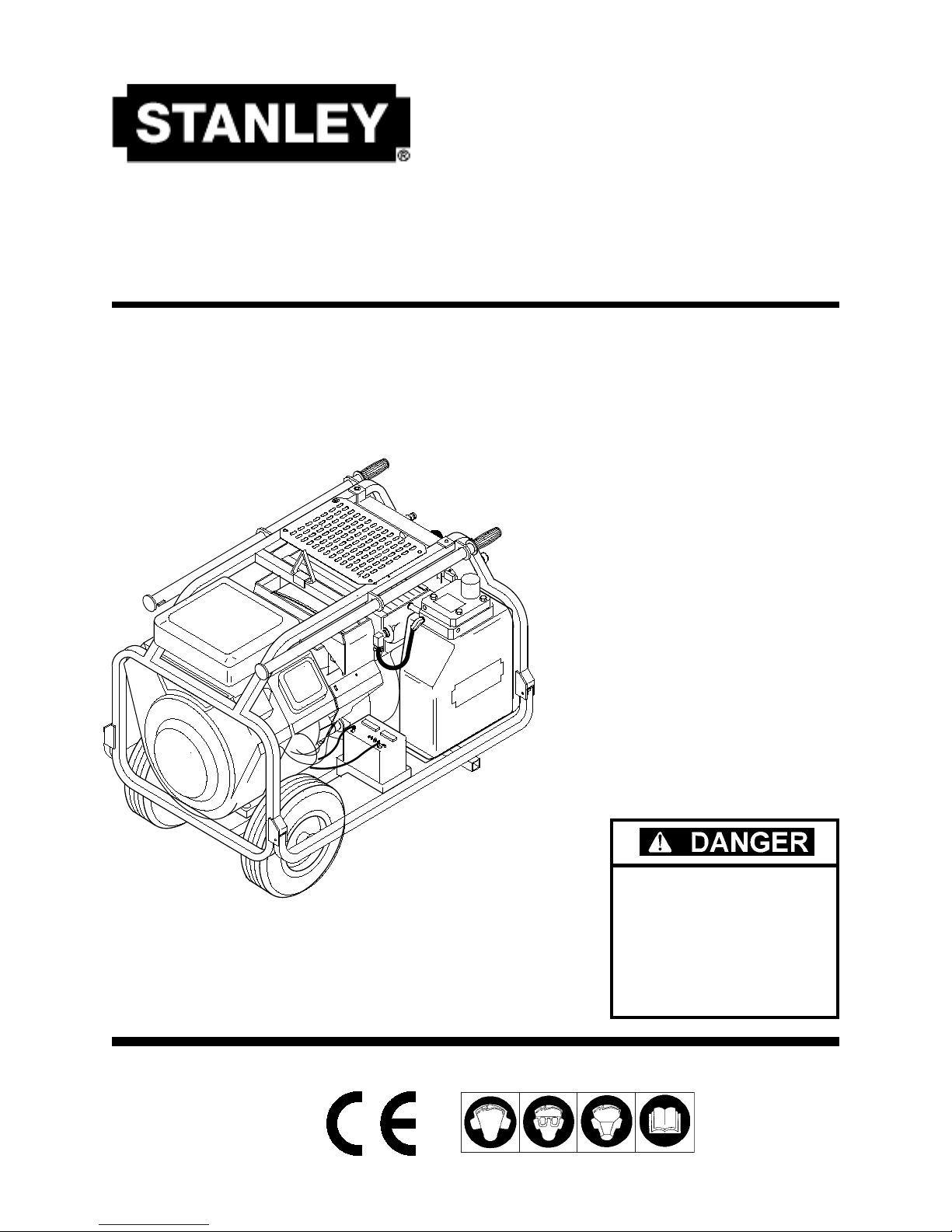
HP1
COMPACT POWER UNIT
Safety, Operation
and
Maintenance
Manual
Copyright © 1998
The Stanley Works
All rights reserved
OPS/MAINT USA & CE VERSION
Printed in U.S.A.
24280 06/97 Ver 3
SERIOUS INJURY OR DEASERIOUS INJURY OR DEA
SERIOUS INJURY OR DEA
SERIOUS INJURY OR DEASERIOUS INJURY OR DEA
COULD RESULCOULD RESUL
COULD RESUL
COULD RESULCOULD RESUL
IMPROPER REPIMPROPER REP
IMPROPER REP
IMPROPER REPIMPROPER REP
OF THIS TOOLOF THIS TOOL
OF THIS TOOL
OF THIS TOOLOF THIS TOOL
REPREP
AIRS AND / OR SERVICE TOAIRS AND / OR SERVICE TO
REP
AIRS AND / OR SERVICE TO
REPREP
AIRS AND / OR SERVICE TOAIRS AND / OR SERVICE TO
THIS TOOL MUST ONLTHIS TOOL MUST ONL
THIS TOOL MUST ONL
THIS TOOL MUST ONLTHIS TOOL MUST ONL
DONE BDONE B
DONE B
DONE BDONE B
CERTIFIED DEALERCERTIFIED DEALER
CERTIFIED DEALER
CERTIFIED DEALERCERTIFIED DEALER
T FROM THET FROM THE
T FROM THE
T FROM THET FROM THE
AIR OR SERVICEAIR OR SERVICE
AIR OR SERVICE
AIR OR SERVICEAIR OR SERVICE
..
.
..
Y AN AY AN A
UTHORIZED ANDUTHORIZED AND
Y AN A
UTHORIZED AND
Y AN AY AN A
UTHORIZED ANDUTHORIZED AND
..
.
..
Y BEY BE
Y BE
Y BEY BE
THTH
TH
THTH
Page 2

INDEX
Index (this page) ...................................................................................... 1
Hydraulic Hose Requirements ................................................................. 6
Operation ......................................................................................... 7 - 10
Preparation for Use ........................................................................... 7
Hydraulic Connections ................................................................ 7 - 8
Startup ...................................................................................... 9 - 10
Cold Weather Startup ..................................................................... 10
Tool Operation .................................................................................10
Optional Equipment ............................................................................... 28
Parts Lists ...................................................................................... 19 - 20
Parts Drawings .............................................................................. 21 - 27
Engine Assembly (Fig. 1) ................................................................ 21
Frame Assemblies (Fig. 2) .............................................................. 22
Choke Cable Assembly (Fig. 3) ...................................................... 23
Actuator Assembly (Fig. 4) .............................................................. 23
Dash Panel & Valve Assembly (Fig. 5) ........................................... 24
Hydraulic Tank & Filter Assembly (Fig. 6) ....................................... 25
Hose & Fitting Connections (Fig. 7) ................................................26
Wiring Diagram (Fig. 8) .................................................................. 27
Routine Maintenance ............................................................................. 11
Engine ............................................................................................. 11
Hydraulic System ............................................................................ 11
Storage............................................................................................ 11
Safety Precautions ............................................................................ 2 - 5
Local Safety Regulation .................................................................... 4
Safety Stickers & Tags ......................................................................5
Sales & Service ......................................................................... Last Page
Service Instructions ....................................................................... 12 - 14
Specification & Capacities ..................................................................... 18
Testing & Troubleshooting ............................................................. 15 - 16
Troubleshooting Chart ........................................................................... 17
Warranty ................................................................................................ 29
SERIOUS INJURY OR DEASERIOUS INJURY OR DEA
SERIOUS INJURY OR DEA
SERIOUS INJURY OR DEASERIOUS INJURY OR DEA
IMPROPER REPIMPROPER REP
IMPROPER REP
IMPROPER REPIMPROPER REP
REPREP
AIRS AND / OR SERVICE TO THIS EQUIPMENT MUSTAIRS AND / OR SERVICE TO THIS EQUIPMENT MUST
REP
AIRS AND / OR SERVICE TO THIS EQUIPMENT MUST
REPREP
AIRS AND / OR SERVICE TO THIS EQUIPMENT MUSTAIRS AND / OR SERVICE TO THIS EQUIPMENT MUST
ONLONL
Y BE DONE BY BE DONE B
ONL
Y BE DONE B
ONLONL
Y BE DONE BY BE DONE B
DEALERDEALER
DEALER
DEALERDEALER
For the nearest authorized and certified dealer, call Stanley Hydraulic Tools at one of the locations listed on the back of this manual.
..
.
..
TH COULD RESULTH COULD RESUL
TH COULD RESUL
TH COULD RESULTH COULD RESUL
AIR OR SERVICE OF THIS EQUIPMENTAIR OR SERVICE OF THIS EQUIPMENT
AIR OR SERVICE OF THIS EQUIPMENT
AIR OR SERVICE OF THIS EQUIPMENTAIR OR SERVICE OF THIS EQUIPMENT
Y AN AY AN A
Y AN A
Y AN AY AN A
UTHORIZED AND CERTIFIEDUTHORIZED AND CERTIFIED
UTHORIZED AND CERTIFIED
UTHORIZED AND CERTIFIEDUTHORIZED AND CERTIFIED
T FROM THET FROM THE
T FROM THE
T FROM THET FROM THE
..
.
..
1
Page 3
SAFETY PRECAUTIONS
Do not operate this equipment or associated
equipment until the following safety instructions have been thoroughly read and understood! Read this manual before installing,
operating or maintaining this equipment.
Tool operators and maintenance personnel must always comply with the safety precautions given in this
manual and on the stickers and tags attached to the equipment.
These safety precautions are given for your safety. Review them carefully before operating the tool and
before performing general maintenance or repairs.
Supervising personnel should develop additional precautions relating to the specific work area and local
safety regulations. If so, place the added precautions in the space provided on page 5.
In addition to this manual, read and understand safety and operating instructions in the Engine
Operation Manual furnished with the power unit.
GENERAL SAFETY PRECAUTIONS
The HP1 Compact Hydraulic Power Unit will provide safe and dependable service if operated in accordance with the instructions given in this manual. Read and understand this manual and any stickers and
tags attached to the Power Unit. Failure to do so could result in personal injury or equipment damage.
• Operators must start in a work area without bystanders. The operator must be familiar with all prohibited work areas such as excessive slopes and dangerous terrain conditions.
• Establish a training program for all operators to ensure safe operation.
• Do not operate the power unit unless thoroughly trained or under the supervision of an instructor.
• Always wear safety equipment such as goggles, ear and head protection, and safety shoes at all times
when operating the power unit and a hydraulic tool.
• Do not inspect or clean the power unit while the unit is running.
• Always use hoses and fittings rated at 2500 psi/172 bar with a 4 to 1 safety factor. Be sure all hose
connections are tight.
• Make sure all hoses are connected for correct flow direction to and from the tool being used.
• Do not inspect hoses and fittings for leaks by using bare hands. "Pin-hole" leaks can penetrate the
skin.
• Never operate the power unit in a closed space. Inhalation of engine exhaust can be fatal.
• Do not operate a damaged or improperly adjusted power unit.
• Never wear loose clothing that can get entangled in the working parts of the power unit.
• Keep all parts of your body away from the working parts of the power unit.
2
Page 4
• Always wear appropriate safety equipment such as goggles, ear protection, and toe guards. Certain
tools used in conjunction with the power unit may require other safety equipment such as breathing
filters.
• Keep clear of hot engine exhaust.
• Do not add fuel to the power unit while the power unit is running or is still hot.
• Do not operate the power unit if gasoline odor is present.
• Do not use flammable solvents around the power unit engine.
• Do not operate the power unit within 3.3 ft/1 m of buildings, obstructions, or flammable objects.
• Do not reverse grinding wheel rotation direction by changing fluid flow direction.
• Allow the engine to cool before storing the power unit in an enclosure.
• To avoid personal injury or equipment damage, all tool repair, maintenance and service must only be
performed by authorized and properly trained personnel.
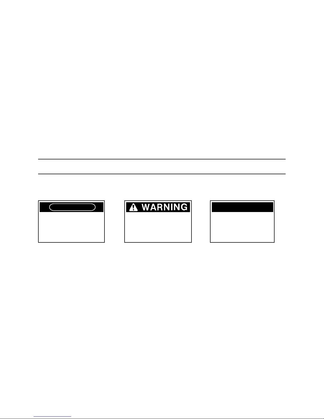
SAFETY SYMBOLS
Safety symbols are used to emphasize all operator, maintenance and repair actions which, if not strictly
followed, could result in a life-threatening situation, bodily injury or damage to equipment.
DANGER
This safety symbol may appear
on the tool. It is used to alert
the operator of an action that
could place him/her or others in
a life threatening situation.
This safety symbol appears in
these instructions to identify
an action that could cause
bodily injury to the operator or
other personnel.
IMPORTANT
This safety symbol appears in
these instructions to identify an
action or condition that could
result in damage to the tool or
other equipment.
Always observe safety symbols. They are included for your safety and for the protection of the tool.
3
Page 5

LOCAL SAFETY REGULATIONS
Enter any local safety regulations here. Keep these instructions in an area accessible to the operator and
maintenance personnel.
4
Page 6

SAFETY STICKERS & TAGS
0110
L
WA
L
WA
CHOKE PULL DECAL
EXHAUST FUMES STICKER
EXHAUST STICKER
WEIGHT STICKER
DO NOT OPERATE THE PUMP WITHOUT WATER. OPERATING THE PUMP
WITHOUT WATER WILL SEVERLY DAMAGE THE PUMP.
FUEL STICKER
SAFETY TAG
Do not remove until read)
HYDRAULIC OIL
STICKER
BATTERY CHARGE TAG
(Do not remove until read)
COUPLER STICKER
BR87, BR37, CH18
BR87, BR37, CH18
L
L
101
11
WA
WA
SOUND POWER LEVER STICKER
MANUAL STICKER
SERIAL NO. LOCATION
(At top of dash panel)
CAUTION STICKER
(If Equipped with Water Pump Kit)
The safety tag at right is
attached to the power unit
when shipped from the
factory. Read and
understand the safety
instructions listed on this
tag before removal. We
suggest you retain this tag
and attach it to the tool
when not in use.
DANGER
1. FAILURE TO USE HYDRAULIC HOSE LABELED AND CERTIFIED AS NON-CONDUCTIVE WHEN USING HYDRAULIC TOOLS
ON OR NEAR ELECTRICAL LINES MAY RESULT IN DEATH OR
SERIOUS INJURY.
BEFORE USING HOSE LABELED AND CERTIFIED AS NON-
CONDUCTIVE ON OR NEAR ELECTRIC LINES BE SURE THE
HOSE IS MAINTAINED AS NON-CONDUCTIVE. THE HOSE
SHOULD BE REGULARLY TESTED FOR ELECTRIC CURRENT
LEAKAGE IN ACCORDANCE WITH YOUR SAFETY DEPARTMENT
INSTRUCTIONS.
2. A HYDRAULIC LEAK OR BURST MAY CAUSE OIL INJECTION
INTO THE BODY OR CAUSE OTHER SEVERE PERSONAL INJURY.
A DO NOT EXCEED SPECIFIED FLOW AND PRESSURE FOR
THIS TOOL. EXCESS FLOW OR PRESSURE MAY CAUSE A
LEAK OR BURST.
B DO NOT EXCEED RATED WORKING PRESSURE OF HYDRAU
LIC HOSE USED WITH THIS TOOL. EXCESS PRESSURE MAY
CAUSE A LEAK OR BURST.
C CHECK TOOL HOSE COUPLERS AND CONNECTORS DAILY
FOR LEAKS. DO NOT FEEL FOR LEAKS WITH YOUR HANDS.
CONTACT WITH A LEAK MAY RESULT IN SEVERE PERSONAL
INJURY.
IMPORTANT
READ OPERATION MANUAL AND
SAFETY INSTRUCTIONS FOR THIS
TOOL BEFORE USING IT.
USE ONLY PARTS AND REPAIR
PROCEDURES APPROVED BY
STANLEY AND DESCRIBED IN THE
OPERATION MANUAL.
TAG TO BE REMOVED ONLY BY
TOOL OPERATOR.
SEE OTHER SIDE
15875
DANGER
D DO NOT LIFT OR CARRY TOOL BY THE HOSES. DO NOT
ABUSE HOSE. DO NOT USE KINKED, TORN OR DAMAGED
HOSE.
3. MAKE SURE HYDRAULIC HOSES ARE PROPERLY CONNECTED
TO THE TOOL BEFORE PRESSURING SYSTEM. SYSTEM PRESSURE HOSE MUST ALWAYS BE CONNECTED TO TOOL "IN"
PORT. SYSTEM RETURN HOSE MUST ALWAYS BE CONNECTED TO TOOL "OUT" PORT. REVERSING CONNECTIONS
MAY CAUSE REVERSE TOOL OPERATION WHICH CAN RESULT
IN SEVERE PERSONAL INJURY.
4. DO NOT CONNECT OPEN-CENTER TOOLS TO CLOSED-CENTER HYDRAULIC SYSTEMS. THIS MAY RESULT IN LOSS OF
OTHER HYDRAULIC FUNCTIONS POWERED BY THE SAME
SYSTEM AND/OR SEVERE PERSONAL INJURY.
5. BYSTANDERS MAY BE INJURED IN YOUR WORK AREA. KEEP
BYSTANDERS CLEAR OF YOUR WORK AREA.
6. WEAR HEARING, EYE, FOOT, HAND AND HEAD PROTECTION.
7. TO AVOID PERSONAL INJURY OR EQUIPMENT DAMAGE, ALL
TOOL REPAIR MAINTENANCE AND SERVICE MUST ONLY BE
PERFORMED BY AUTHORIZED AND PROPERLY TRAINED PERSONNEL.
IMPORTANT
READ OPERATION MANUAL AND
SAFETY INSTRUCTIONS FOR THIS
TOOL BEFORE USING IT.
USE ONLY PARTS AND REPAIR
PROCEDURES APPROVED BY
STANLEY AND DESCRIBED IN THE
OPERATION MANUAL.
TAG TO BE REMOVED ONLY BY
TOOL OPERATOR.
SEE OTHER SIDE
15875
SAFETY TAG
(shown smaller then actual size)
5
Page 7

HYDRAULIC HOSE REQUIREMENTS
HOSE TYPES
Hydraulic hose types authorized for use with Stanley Hydraulic Tools are as follows:
1
2
3
Hose listed above is the only hose authorized for use near electrical conductors.
Hoses and listed above are conductive and must never be used near electrical conductors.
Certified non-conductive
Wire-braided (conductive)
Fabric-braided (not certified or labeled non-conductive)
1
32
To help ensure your safety, the following DANGER tags are attached to all hose purchased from Stanley.
DO NOT REMOVE THESE TAGS.
If the information on a tag is illegible because of wear or damage, replace the tag immediately. A new
tag may be obtained at no charge from your Stanley Distributor.
CERTIFIED NON-CONDUCTIVE HOSE
1
This tag is attached to all certified non-conductive hose.
D A N G E R
1 FAILURE TO USE HYDRAULIC HOSE LABELED AND CERTIFIED AS NON-CONDUCTIVE
WHEN USING HYDRAULIC TOOLS ON OR NEAR ELECTRIC LINES MAYRESULT IN DEATH
OR SERIOUS INJURY.
FOR PROPER AND SAFE OPERATION MAKE SURE THAT YOU HAVE BEEN PROPERLY
TRAINED IN CORRECT PROCEDURES REQUIRED FOR WORK ON OR AROUND ELECTRIC
LINES.
2. BEFORE USING HYDRAULIC HOSE LABELED AND CERTIFIED AS NON-CONDUCTIVE ON OR
NEAR ELECTRIC LINES. WIPE THE ENTIRE LENGTH OF THE HOSE AND FITTING WITH A
CLEAN DRY ABSORBENT CLOTH TO REMOVE DIRT AND MOSISTURE AND TEST HOSE FOR
MAXIMUM ALLOWABLE CURRENT LEAKAGE IN ACCORDANCE WITH SAFETY
DEPARTMENT INSTRUCTIONS.
DO NOT REMOVE THIS TAG
SEE OTHER SIDE
D A N G E R
3. DO NOT EXCEED HOSE WORKING PRESSURE OR ABUSE HOSE. IMPROPER USE OR
HANDLING OF HOSE COULD RESULT IN BURST OR OTHER HOSE FAILURE. KEEP HOSE AS
FAR AWAY AS POSSIBLE FROM BODY AND DO NOT PERMIT DIRECT CONTACT DURING
USE. CONTACT AT THE BURST CAN CAUSE BODILY INJECTION AND SEVERE PERSONAL
INJURY.
4. HANDLE AND ROUTE HOSE CAREFULLY TO AVOID KINKING, ABRASION, CUTTING, OR
CONTACT WITH HIGH TEMPERATURE SURFACES. DO NOT USE IF KINKED. DO NOT USE
HOSE TO PULL OR LIFT TOOLS, POWER UNITS, ETC.
5. CHECK ENTIRE HOSE FOR CUTS CRACKS LEAKS ABRASIONS, BULGES, OR DAMAGE TO
COUPLINGS IF ANY OF THESE CONDITIONS EXIST, REPLACE THE HOSE IMMEDIATELY.
NEVER USE TAPE OR ANY DEVICE TO ATTEMPT TO MEND THE HOSE.
6. AFTER EACH USE STORE IN A CLEAN DRY AREA.
SEE OTHER SIDE
DO NOT REMOVE THIS TAG
SIDE 1 SIDE 2
2
AND 1 WIRE-BRAIDED AND FABRIC-BRAIDED (NOT CERTIFIED OR LABELED NON-CON-
3
DUCTIVE) HOSE
This tag is attached to all conductive hose.
D A N G E R
1 DO NOT USE THIS HYDRAULIC HOSE IN OR NEAR ELECTRIC LINES. THIS HOSE IS NOT
LABELED OR CERTIFIED AS NON-CONDUCTIVE. USING THIS HOSE ON OR NEAR
ELECTRICAL LINES MAY RESULT IN DEATH OR SERIOUS INJURY.
2. FOR PROPER AND SAFE OPERATION MAKE SURE THAT YOU HAVE BEEN PROPERLY
TRAINED IN CORRECT PROCEDURES REQUIRED FOR WORK ON OR AROUND ELECTRIC
LINES.
3. DO NOT EXCEED HOSE WORKING PRESSURE OR ABUSE HOSE. IMPROPER USE OR
HANDLING OF HOSE COULD RESULT IN BURST OR OTHER HOSE FAILURE. KEEP HOSE
AS FAR AWAY AS POSSIBLE FROM BODY AND DO NOT PERMIT DIRECT CONTACT
DURING USE. CONTACT AT THE BURST CAN CAUSE BODILY INJECTION AND SEVERE
PERSONAL INJURY.
4. HANDLE AND ROUTE HOSE CAREFULLY TO AVOID KINKING, CUTTING, OR CONTACT WITH
HIGH TEMPERATURE SURFACES. DO NOT USE IF KINKED. DO NOT USE HOSE TO PULL
OR LIFT TOOLS, POWER UNITS, ETC.
DO NOT REMOVE THIS TAG
SEE OTHER SIDE
SIDE 1 SIDE 2
HOSE PRESSURE RATING
The rated working pressure of the hydraulic hose must be equal or higher than the relief valve setting on
the hydraulic system.
6
(shown smaller then actual size)
5. CHECK ENTIRE HOSE FOR CUTS CRACKS LEAKS ABRASIONS, BULGES, OR DAMAGE TO
COUPLINGS IF ANY OF THESE CONDITIONS EXIST, REPLACE THE HOSE IMMEDIATELY.
NEVER USE TAPE OR ANY DEVICE TO ATTEMPT TO MEND THE HOSE.
6. AFTER EACH USE STORE IN A CLEAN DRY AREA.
(shown smaller then actual size)
D A N G E R
SEE OTHER SIDE
DO NOT REMOVE THIS TAG
Page 8

OPERATING INSTRUCTIONS
PREPARATION FOR USE
Do not operate the power unit until you have
read the engine operating and maintenance
instructions manual furnished with the unit.
1. ENGINE CRANKCASE OIL LEVEL
IMPORTANT
Do not start the Engine with the
Always check the oil level before starting tne
engine. Make sure the oil level is at the FULL
MARK on the dipstick. Do not overfill. Use detergent oil classified "For Service SE, SF, SG" as
specified in the engine operating and maintenance
manual.
trottle control set at 5 or 8 gpm/
19 or 30 lpm.
Flash Point (ASTM D-92) 340°F/171°C Minimum
Rust Inhibition (ASTM D-665 A & B) Pass
Oxidation (ASTM D-943) 1000 Hours Minimum
Pump Wear Test (ASTM D-2882) 60 mg Maximum
The following fluids work well over a wide temperature range, allow moisture to settle out and resist
biological growth that may occur in cool operating
hydraulic circuits. These fluids are recommended
by Stanley. Other fluids that meet or exceed the
specifications of these fluids may also be used.
Chevron AW-MV-32
Exxon "Univis" J-26
Mobil D.T.E. 13
Gulf "Harmony" AW-HVI-150-32
Shell "Tellus" T-32
Texaco "Rando" HD-AZ
Union "Unax" AW-WR-32
2. ENGINE FUEL LEVEL
Check the fuel level. If low, fill with un-leaded
gasoline with a minimum of 85 octane.
3. HYDRAULIC FLUID
Check the sight pipe in the hydraulic fluid reservoir
for the proper fiuid level. Proper fluid level is
indicated when the center section of the sight pipe
is dark. If the center section of the sight pipe is not
dark, add hydraulic fluid. Use fluids meeting the
following specifications.
Viscosity (Fluid Thickness)
U.S. METRIC
50°F 450 SSU Maximum 10°C 95 Centistokes
100°F 130-200 SSU 38°C 27-42 C.S.
140°F 85 SSU Minimum 60°C 16.5 C.S. Minimum
PourPoint -10°F/-23°C Minimum (for cold startup)
Viscosity Index (ASTM D-2220) 140 Minimum
4. HYDRAULIC CONNECTIONS
Facing the panel control valve, the far right-hand
male quick disconnect fitting is the pressure
(FLUID OUT) fitting. The left-hand female quick
disconnect fitting is the return (FLUID IN) fitting.
The recommended hose length is 25 ft/8 m with a
1/2 inch/12.7 mm inside diameter. The hoses
must have a working pressure rating of at least
2500 psi/175 bar. Each hose end must have male
thread ends compatible with H.T.M.A. (HYDRAULIC TOOL MANUFACTURERS ASSOCIATION)
5. BATTERY
The supplied 12 Volt DC battery has been partially
dry charged. Before using, it must first be filled
with battery electrolyte at a specific density of
1.240 to 1.260. Fill each cell to its upper level
indicator and then charge at a 2 Amp rate for at
least 12 to 15 hours. After charging, check the
electrolyte level and fill as required.
Demulsibility (ASTM D-1401) 30 Minutes Maximum
Also, make sure the battery cables are tight and
charging circuit functions are operating properly.
7
Page 9

quick disconnect fittings (NPT type threads).
(See Figure 1.)
CONTROL PANEL
PRESSURE
RETURN
H.T.M.A. 1/2 INCH
FEMALE QUICK
DISCONNECT COUPLER
H.T.M.A. 1/2 INCH MALE
QUICK DISCONNECT
COUPLER
1/2 INCH MALE PIPE
HOSE END
1/2 INCH I.D. HOSE, 25 FT
LONG WITH 2500 PSI/
172 BAR RATING AND
4 TO 1 SAFETY FACTOR
Longer hoses may be used when necessary,
but can effect the operation of the engine
automatic throttle due to fluid resistance in the
hose. If small diameter or long hoses are
used, or if restrictive fittings are connected to
the supply and return ports, the pressure
required to push the fluid through the system
and back to the hydraulic tank will be higher.
If the pressure is too high, this will cause the
engine RPM to remain at full load if "AUTO" is
selected on the automatic throttle. Also see
"HYDRAULIC HOSE REQUIREMENTS"
earlier in this manual.
QUICK DISCONNECT COUPLERS
H.T.M.A. approved quick disconnect couplings
are installed to hydraulic hoses so that the
direction of oil flow is always from the male to
the female quick disconnect as shown in figure
1. Quick disconnect couplings and hose
fittings are selected so that additional fittings
such as reducer or adapter fittings are not
required.
1/2 INCH MALE PIPE
HOSE END
H.T.M.A. 1/2 INCH
FEMALE QUICK
DISCONNECT COUPLER
H.T.M.A. 1/2 INCH MALE
QUICK DISCONNECT
COUPLER
ADAPTER, 3/8 INCH MALE
PIPE x -8 SAE O-RING
RETURN
PRESSURE
If adapter fittings are used, they must be
PRESSURERETURN
approved steel hydraulic fittings meeting a
minimum operating pressure rating of 2500
psi/172 bar. Do not use galvanized pipe
fittings or black pipe fittings.
Use thread tape or pipe joint compound when
installing quick disconnect couplings to hose or
tool fittings. Follow the instructions furnished
with the selected thread sealant. DO NOT
OVERTIGHTEN THE FITTINGS.
TOOL
Figure 1. Hydraulic Connections
8
Page 10

Do not charge the battery with a
standard automotive battery
charger. This type of charger
produces a charging amperage
higher than 2 amps. Charging the
battery with amperage higher than
2 amps will damage the battery.
6. THROTTLE CONTROL (See Figure 2)
The throttle control permits the operator to select
one of 3 operating modes after the engine has
warmed up. For startup, the throttle control should
be set on "AUTO".
a. AUTO - Engine speed varies with hydraulic
circuit pressure to maintain a constant 8.5 gpm/32
lpm. When a tool is not being used the engine will
return to idle automatically.
b. 5 - Engine speed is held at part throttle to
maintain 5 gpm/19 lpm. When a tool is not being
used the engine will not return to idle until the
faspin is removed.
CYLINDER
LEVER
FASPIN
AUTO
HOLD 5 GPM
BASE
GOVERNOR
LEVER
c. 8 - Engine speed is held at full throttle to
maintain 8.5 gpm/32 lpm. When a tool is not
being used the engine will not return to idle until
the faspin is removed.
Typical conditions requiring the "8" position are:
• When operating an alternator, fluid flow must be
constant to produce the required voltage and
frequency, even when load requirements are light.
• When operating drills or grinders or diamond
saws, tool rpm must be maintained even when
load requirements are light.
HOLD 8 GPM
Figure 2. Throttle Control Settings
STARTUP - See "PANEL CON-
TROLS" - Figure 3
1. Assure the circuit control lever is in the "OFF"
position.
2. Select the "AUTO" throttle operating mode by
positioning the governor lever to the cylinder lever
and inserting the faspin as shown in figure 2.
9
Page 11

ON/OFF
SWITCH
ON
OFF
ENGINE
TOOL
RETURN
HOSE
OFF
Stanley Hydraulic Tools
MILWAUKIE, OREGON
TOOL
ON
PRESSURE
HOSE
HP1 COMPACT POWER UNIT
3. If the tools and tool hoses are cold, it is
recommended to allow hydraulic fluid to
circulate through the tool hoses until warm
before using the tool.
TOOL OPERATION
1. With the engine running smoothly,
move the control lever to the "ON" position.
2. Activate the tool. The automatic throttle
will increase engine speed to permit proper
tool operation. When the tool is deactivated, the automatic throttle allows the
engine to return to idle.
3. If automatic throttle operation is not
desired, change the throttle control to "5 or
8".
RETURN QUICK
DISCONNECT
PRESSURE QUICK
DISCONNECT
Figure 3. Control Panel
3. Position the ON/OFF switch to the "ON"
position.
4. Pull the choke lever out.
5. Push the circuit control lever to the "START"
position.
6. After the engine starts, allow the engine to
warm up until it runs smoothly with the choke
released.
IMPORTANT
Do not start the Engine with the
trottle control set at 5 or 8 gpm/
19 or 30 lpm.
SHUTDOWN
1. Place the circuit control lever in the
"OFF" position.
2. If the throttle control is in the "5" or "8" position,
change it to the "AUTO" position.
3. Allow the engine to idle for approximately one
minute and then switch the ON/OFF switch to the
"OFF" position.
OPTIONAL WATER
PUMP KIT
DO NOT OPERATE THE PUMP WITHOUT WATER. OPERATING THE PUMP
WITHOUT WATER WILL SEVERLY DAMAGE THE PUMP.
COLD WEATHER
STARTUP
1. Use the procedures described under
"STARTUP" and then follow the procedure below.
2. Hydraulic fluids are thicker in cold weather,
therefore, it is recommended that the engine be
run at low idle long enough to bring the fluid
temperature up to a minimum of 50°F/10°C or
until the top of the hydraulic filter feels warm.
10
If the power unit will be operated without need of
the water pump, unpin the water pump and
remove it.
Page 12

ROUTINE MAINTENANCE
ENGINE MAINTENANCE
Follow the maintenance schedule and general
maintenance instructions in the engine maintenance and operation manual furnished with the
power unit. Normal maintenance includes:
• Service foam air pre-cleaner every 25 hours of
operation.
• Service air paper cartridge every 100 hours of
operation.
• Replace in-line fuel filter every 100-300 hours or
sooner if required.
• Replace spark plugs every 100 hours of operation.
• Change engine oil after first 5 hours of operation, then after every 50 hours of operation. If
engine has been operating under heavy load or
in high ambient temperature, change the oil
every 25 hours of operation.
• Change oil filter when engine oil is changed.
• Check oil level daily.
• Remove dirt and debris from engine with a cloth
or brush daily. Do not use water spray.
• Clean air cooling system every 100 hours of
operation.
avoiding the water at the bottom of the container.
• Each day, check hydraulic lines and fittings for
leaks, kinks, etc. Do not use your hand to
perform this check.
• Change the hydraulic filter element every 200
hours of operation. Change more often if cold,
moist or dusty conditions exist.
• Check oil cooler for debris. Remove debris with
air pressure.
STORAGE
• Clean the unit thoroughly before storage. Do
not use water pressure.
• Always store the unit in a clean and dry facility.
• If the unit will be stored for a prolonged period
(over 30 days), add a fuel additive to the fuel
tank to prevent the fuel from gumming. Run
engine for a short period to circulate the additive.
• Replace crankcase oil with new oil.
• Remove spark plugs and pour approximately 1
ounce (30 ml) of engine oil into each cylinder.
Replace spark plugs and crank the engine
slowly to distribute the oil.
HYDRAULIC SYSTEM MAINTENANCE
• Check hydraulic fluid level daily. The center of
the sight pipe on the reservoir must be dark. If
it is not dark, fluid must be added. Add fluid per
specifications in this manual. (See "HYDRAULIC FLUID" under the section titled "OPERATING INSTRUCTIONS".
• Remove condensed moisture from the hydraulic
fluid by pumping the hydraulic fluid into a 5 gal/20
ltr container through the pressure hose. Make
sure the engine is at idle when performing this
procedure. When the hydraulic reservoir is empty
turn the engine off immediately.
• Allow the fluid to sit long enough for the water to
settle to the bottom of the container. Slowly
pour the fluid back into the hydraulic tank,
• Check hydraulic reservoir for water. If water is
found, change the oil and circulate it through the
tool hose and tool. (See "HYDRAULIC SYSTEM MAINTENANCE" earlier in this section).
• Disconnect tool hoses.
11
 Loading...