

Page 1
WARNING
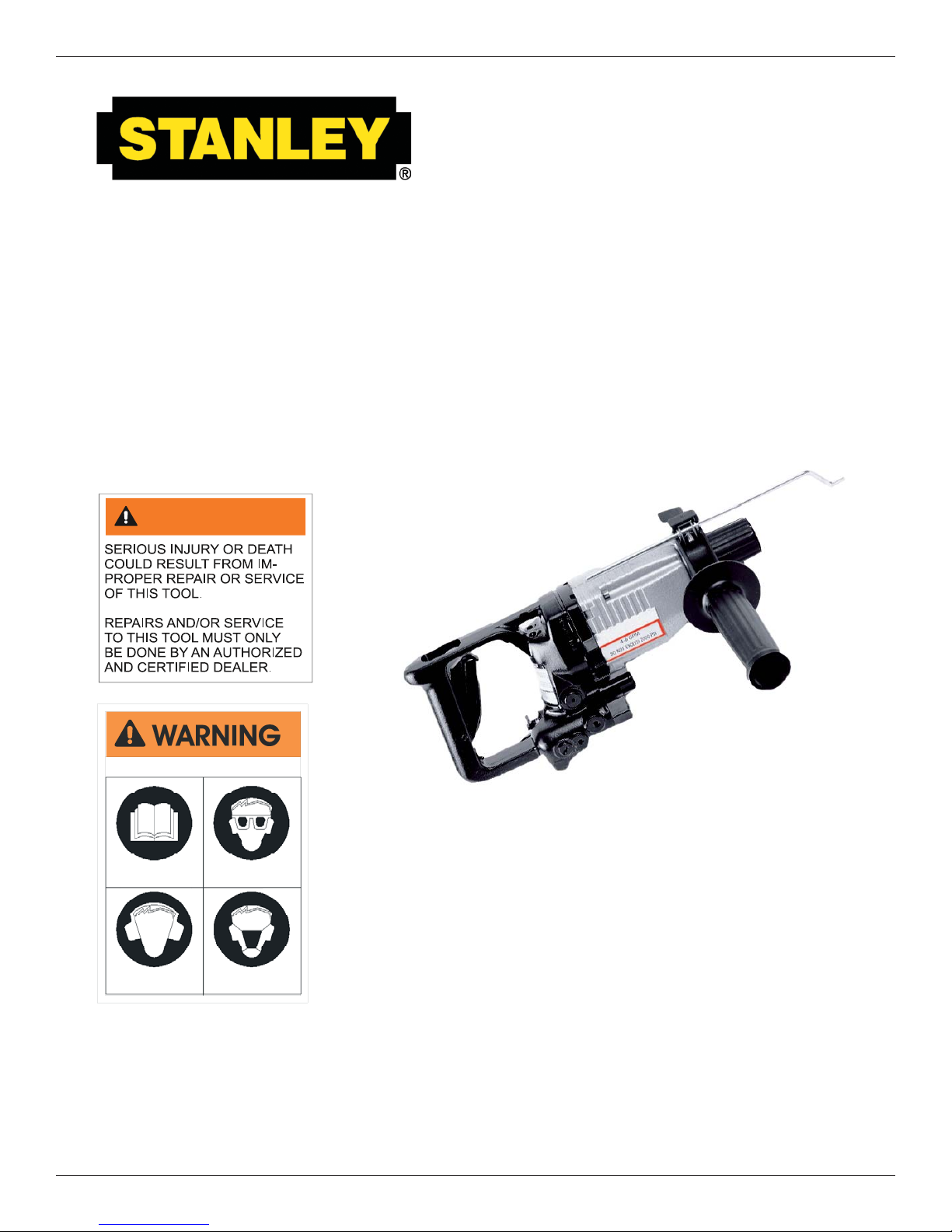
HD08
HYDRAULIC
HAMMER DRILL
To avoid serious injury or death
Read the Manual
Wear Ear
Protection
© Stanley Hydraulic Tools 2004
OPS/MAINT USA
Printed in U.S.A.
65301 9/2005 ver 3
Wear Eye
Protection
Wear Dust Mask
47351
SAFETY, OPERATION AND MAINTENANCE
USER'S MANUAL
Stanley Hydraulic Tools
3810 SE Naef Road
Milwaukie OR 97267-5698
503-659-5660
FAX 503-652-1780
www.stanley-hydraulic-tools.com
1
Page 2

2
Page 3

TABLE OF CONTENTS
CERTIFICATE OF CONFORMITY ........................................................................................................................................... 4
SAFETY SYMBOLS ................................................................................................................................................................. 5
SAFETY PRECAUTIONS ........................................................................................................................................................6
TOOL STICKERS & TAGS ......................................................................................................................................................7
HYDRAULIC HOSE REQUIREMENTS ...................................................................................................................................8
HTMA REQUIREMENTS ......................................................................................................................................................... 9
OPERATION .......................................................................................................................................................................... 10
PREOPERATION PROCEDURES ..................................................................................................................................... 10
CHECK POWER SOURCE ................................................................................................................................................ 10
CHECK THE TOOL ............................................................................................................................................................10
CONNECT HOSES ............................................................................................................................................................10
DETERMINE TOOL MODEL .............................................................................................................................................. 10
FORWARD/REVERSE ....................................................................................................................................................... 10
HAMMER DRILL OR DRILL ONLY .................................................................................................................................... 11
DEPTH GAUGE ................................................................................................................................................................. 11
SIDE HANDLE ................................................................................................................................................................... 11
BIT INSTALLATION ............................................................................................................................................................ 11
DRILL OPERATION ...........................................................................................................................................................12
MODES OF OPERATION ..................................................................................................................................................12
DRILLING (NON-PERCUSSION) ......................................................................................................................................12
HAMMER DRILLING (PERCUSSION) ............................................................................................................................... 12
CHISELLING ...................................................................................................................................................................... 12
TOOL EQUIPMENT & CARE ................................................................................................................................................. 14
TROUBLESHOOTING ........................................................................................................................................................... 15
SPECIFICATIONS ................................................................................................................................................................. 17
ACCESSORIES ..................................................................................................................................................................... 17
SERVICE PARTS .................................................................................................................................................................. 17
PARTS ILLUSTRATION ......................................................................................................................................................... 18
PARTS LIST ........................................................................................................................................................................... 19
WARRANTY ........................................................................................................................................................................... 20
SERVICING THE STANLEY HYDRAULIC HAMMER DRILL. This manual contains safety, operation, and
routine maintenance instructions. Stanley Hydraulic Tools recommends that servicing of hydraulic tools,
other than routine maintenance, must be performed by an authorized and certifi ed dealer. Please read
the following warning.
SERIOUS INJURY OR DEATH COULD RESULT FROM THE IMPROPER REPAIR OR SERVICE OF THIS TOOL.
REPAIRS AND / OR SERVICE TO THIS TOOL MUST ONLY BE
DONE BY AN AUTHORIZED AND CERTIFIED DEALER.
For the nearest authorized and certifi ed dealer, call Stanley Hydraulic Tools at the number listed on the
back of this manual and ask for a Customer Service Representative.
WARNING
3
Page 4
CERTIFICATE OF CONFORMITY
CERTIFICATE OF CONFORMITY
ÜBEREINSTIMMUNGS-ZERTIFIKAT
CERTIFICAT DE CONFORMITE CEE
CERTIFICADO DE CONFORMIDAD
CERTIFICATO DI CONFORMITA
______________________________________________________________________
Hydraulic Tools
I, the undersigned:
Ich, der Unterzeichnende:
Je soussigné:
El abajo firmante:
lo sottoscritto:
hereby certify that the construction plant or equipment specified hereunder:
bestätige hiermit, daß das im folgenden genannten Werk oder Gerät:
certifies par ceci que l’ usine ou l’ équipement de construction indiqué cidessous:
por el presente certifico que la fabrica o el equipo especificado a continuacion:
certifico che l’impianto o l’attrezzatura sotto specificata:
1. Category: Hammer Drill, Hydraulic
Kategorie:
Catégorie:
Categoria:
Categoria:
2. Make/Ausführung/Marque/Marca/Marca
3. Type/Typ/Type/Tipo/Tipo: HD0853101
4. Serial number of equipment:
Seriennummer des Geräts:
Numéro de série de l’équipement:
Numero de serie del equipo:
Matricola dell´attrezzatura:
5. Year of manufacture/Baujahr/année de fabrication/Año de fabricacion/Anno di fabbricazione 2005
Has been manufactured in conformity with - EEC Type examination as shown.
Wurde hergestellt in Übereinstimmung mit - EEC Typ-Prüfung nach.
Est fabriqué conformément - au(x) type(s) examiné(s) comme indiqué dans le tableau ci-après.
Ha sido fabricado de acuerdo con - tipo examen EEC como dice.
E’ stata costruita in conformitá con - le norme CEE come illustrato.
Burrows, James
Surname and First names/Familiennn ame und Vornamen/Nom et prénom /Nombre y apellido/Cognome e nome
Stanley
All
Examen CEE de type
Directive
Richtlinie
Directives particulières
Directriz
Direttiva
EN
EN ISO
EN
EN ISO
Machinery directive
6. Special Provisions: None
Spezielle Bestimmungen:
Dispositions particulières:
Provisiones especiales:
Disposizioni speciali:
Done at/Ort/Fait à/Dado en/Fatto a Stanley Hydraulic Tools, Milwaukie, Oregon USA
Signature/Unterschrift/Signature/Firma/Firma____________________________________________________________________________
Position/Position/Fonction/Puesto/Posizione Engineering Manager
No.
Nr
Numéro
No
n.
292
8662-3
792-5
3744
98/37/EC
Date
Datum
Date
Fecha
Data
1992
1994
1994
1998
Approved body
Prüfung durch
Organisme agréé
Aprobado
Collaudato
Self
Self
Self
Self
Self
Date/Datum/le/Fecha/Data 9/14/05
Date of expiry
Ablaufdatum
Date d´expiration
Fecha de caducidad
Data di scadenza
NA
NA
NA
NA
NA
4
Page 5
SAFETY SYMBOLS
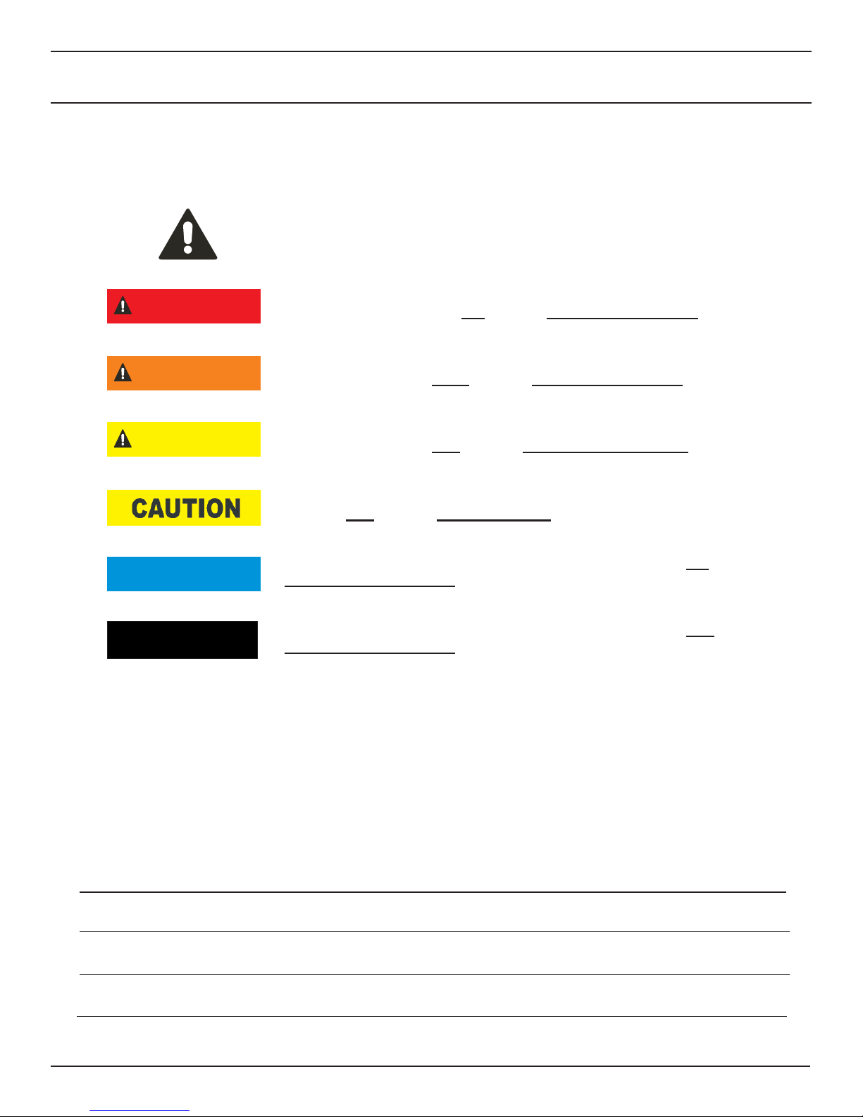
Safety symbols and signal words, as shown below, are used to emphasize all operator, maintenance and repair actions
which, if not strictly followed, could result in a life-threatening situation, bodily injury or damage to equipment.
This is the safety alert symbol. It is used to alert you to potential personal
injury hazards. Obey all safety messages that follow this symbol to avoid
possible injury or death.
This safety alert and signal word indicate an imminently hazardous situa-
DANGER
WARNING
CAUTION
tion which, if not avoided, will result in death or serious injury.
This safety alert and signal word indicate a potentially hazardous situation
which, if not avoided, could result in death or serious injury.
This safety alert and signal word indicate a potentially hazardous situation
which, if not avoided, may result in minor or moderate injury.
This signal word indicates a potentially hazardous situation which, if not
avoided, may result in property damage.
This signal word indicates a situation which, if not avoided, will result in
NOTICE
IMPORTANT
Always observe safety symbols. They are included for your safety and for the protection of the tool.
damage to the equipment.
This signal word indicates a situation which, if not avoided, may result in
damage to the equipment.
LOCAL SAFETY REGULATIONS
Enter any local safety regulations here. Keep these instructions in an area accessible to the operator and maintenance personnel.
5
Page 6
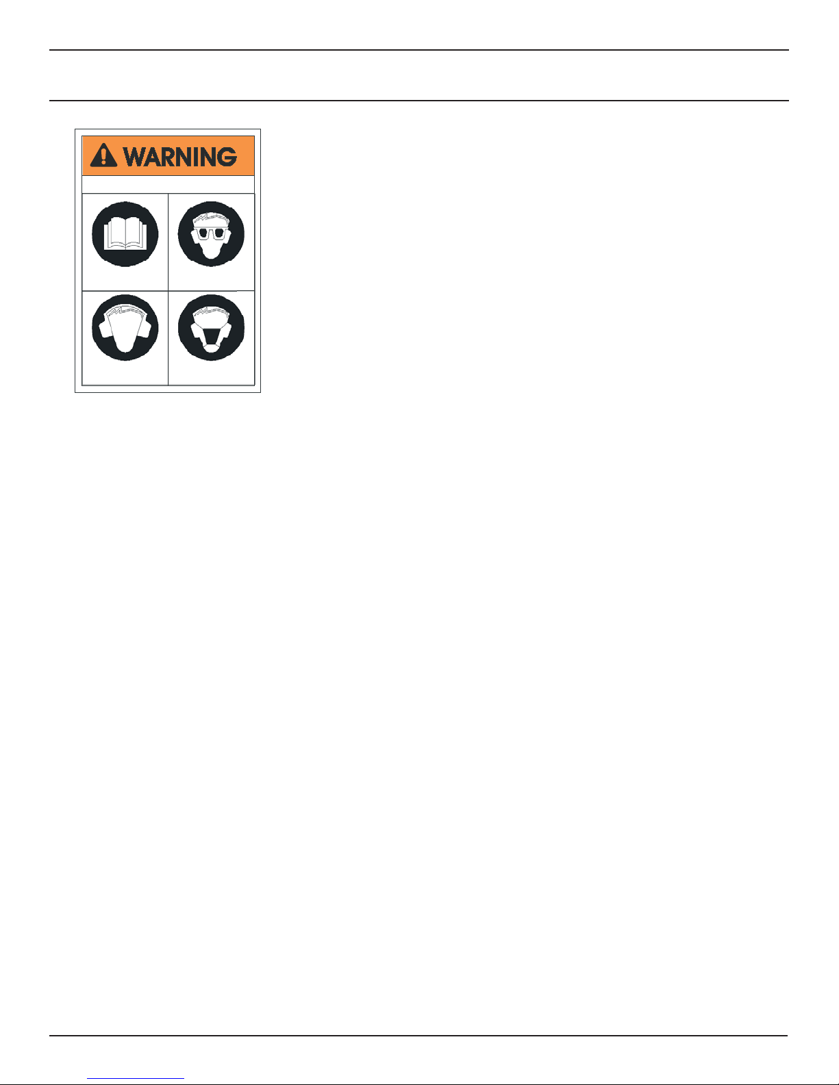
SAFETY PRECAUTIONS
Tool operators and maintenance personnel must always comply with the safety
precautions given in this manual and on the stickers and tags attached to the tool
and hose.
To avoid serious injury or death
Read the Manual
Wear Ear
Protection
Wear Eye
Protection
Wear Dust Mask
• The operator must start in a work area without bystanders. Flying debris can cause serious injury.
• Do not operate the tool unless thoroughly trained or under the supervision of an instructor. Establish a training program
for all operators to ensure safe operation.
These safety precautions are given for your safety. Review them carefully before
operating the tool and before performing general maintenance or repairs.
Supervising personnel should develop additional precautions relating to the specifi c
work area and local safety regulations. If so, place the added precautions in the
space provided on page 5.
The model HD08 Hydraulic Hammer Drill will provide safe and dependable service if
operated in accordance with the instructions given in this manual. Read and understand this manual and any stickers and tags attached to the tool and hose before
operation. Failure to do so could result in personal injury or equipment damage.
47351
• Always wear safety equipment such as goggles, ear and head protection, and safety shoes at all times when operating
the tool. Use gloves and aprons when necessary.
• The operator must be familiar with all prohibited work areas such as excessive slopes and dangerous terrain conditions.
• Do not inspect, clean or replace any part(s) if the hydraulic power source is connected. Do not inspect or clean the tool
while the hydraulic power source is connected. Accidental engagement of the tool can cause serious injury.
• Always connect hoses to the tool hose couplers before energizing the hydraulic power source. Be sure all hose connections are tight and are in good condition.
• Do not operate the tool at oil temperatures above 140°F/60°C. Operation at higher temperatures can cause higher than
normal temperatures at the tool which can result in operator discomfort.
• Do not operate a damaged, improperly adjusted, or incompletely assembled hammer drill.
• Never wear loose clothing that can get entangled in the working parts of the tool.
• Keep all parts of your body away from the drill and maintain proper footing and balance at all times.
• When working near electrical conductors, always assume that all conductors are energized and that insulation, clothing
and hoses can conduct electricity. Stay a safe distance away from electrical conductors.
• If the hydraulic power supply has been interrupted, place the hammer drill in the OFF position before restarting the hydraulic power supply.
• To avoid personal injury or equipment damage, all tool repair, maintenance and service must only be performed by authorized and properly trained personnel.
6
Page 7
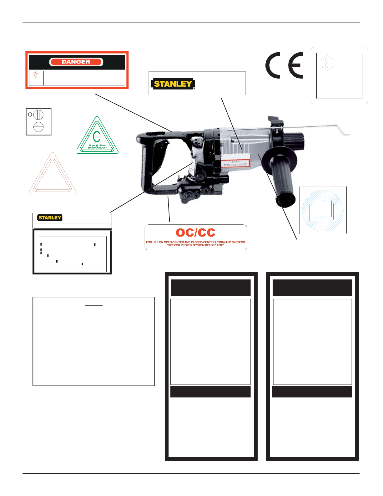
Failure to use hydraulic hose labeled and
C
certified as non-conductive when using
hydraulic tools on or near electric lines
ELECTROCUTION
may result in death or serious injury.
HAZARD
17160
Electrical Danger Decal
C
C
17162
OC/CC Decal
11206
Circuit C Decal
D
30 LPM @ 138 B AR
EHTMA CATEGORY
11207
Circuit D Decal
Staney Hydraulic Tools
3810 SE Naef Road
Miwaukie, OR 97267
Model No.:
DO NOT EXCEED 140 BAR/2000 PSI
DO NOT EXCEED SPECIFIED FLOW OR PRESSURE. USE
CLOSED-CENTER TOOL ON CLOSED-CENTER SYSTEM.
USE OPEN-CENTER TOOL ON OPEN-CENTER SYSTEM.
CORRECTLY CONNECT HOSES TO TOOL "IN" AND "OUT"
PORTS. IMPROPER HANDLING, USE OR MAINTENANCE OF
TOOL COULD RESULT IN A LEAK, BURST OR OTHER
TOOL FAILURE. CONTACT AT A LEAK OR BURST CAN
CAUSE OIL INJECTION INTO THE BODY. FAILURE TO
OBSERVE THESE PRECAUTIONS CAN RESULT IN SERIOUS
PERSONAL INJURY.
HD08
CAUTION
15-34 LPM/4-9 GPM
TOOL STICKERS & TAGS
For proper and safe operation read
owners manual and make sure that you
have been properly trained in correct
procedures required for work on or
around electric lines.
17179
Stanley Decal
11354
OC/CC Decal
Stanley Hydraulic Tools
3810 SE Naef Road
Milwaukie, OR 97267
28323
CE Decal
Lwa
105
_______
22796
Sound Power
Level Decal
28788
Manual Decal
17161
HD08 Name Tag/GPM Decal
NOTE
THE INFORMATION LISTED ON
THE STICKERS SHOWN, MUST BE
LEGIBLE AT ALL TIMES.
REPLACE DECALS IF THEY
BECOME WORN OR DAMAGED.
REPLACEMENTS ARE AVAILABLE
FROM YOUR LOCAL STANLEY
DISTRIBUTOR.
The safety tag (p/n
15875) at right is attached
to the tool when shipped
from the factory. Read
and understand the safety
instructions listed on this
tag before removal. We
suggest you retain this tag
and attach it to the tool
when not in use.
DANGER
1. FAILURE TO USE HYDRAULIC HOSE LABELED AND CERTIFIED
AS NON-CONDUCTIVE WHEN USING HYDRAULIC TOOLS
ON OR NEAR ELECTRICAL LINES MAY RESULT IN DEATH
OR SERIOUS INJURY.
BEFORE USING HOSE LABELED AND CERTIFIED AS NON-
CONDUCTIVE ON OR NEAR ELECTRIC LINES BE SURE THE
HOSE IS MAINTAINED AS NON-CONDUCTIVE. THE HOSE
SHOULD BE REGULARLY TESTED FOR ELECTRIC CURRENT
LEAKAGE IN ACCORDANCE WITH YOUR SAFETY DEPARTMENT INSTRUCTIONS.
2. A HYDRAULIC LEAK OR BURST MAY CAUSE OIL INJECTION
INTO THE BODY OR CAUSE OTHER SEVERE PERSONAL
INJURY.
A DO NOT EXCEED SPECIFIED FLOW AND PRESSURE FOR
THIS TOOL. EXCESS FLOW OR PRESSURE MAY CAUSE A
LEAK OR BURST.
B DO NOT EXCEED RATED WORKING PRESSURE OF HY-
DRAU LIC HOSE USED W ITH THIS
TOOL. EXCESS PRESSURE MAY
CAUSE A LEAK OR BURST.
C CHECK TOOL HOSE COUPLERS AND CONNECTORS DAILY
FOR LEAKS. DO NOT FEEL FOR LEAKS WITH YOUR
HANDS. CONTACT WITH A LEAK MAY
RESULT IN SEVERE PERSONAL INJURY.
IMPORTANT
READ OPERATION MANUAL AND
SAFETY INSTRUCTIONS FOR THIS
TOOL BEFORE USING IT.
USE ONLY PARTS AND REPAIR
PROCEDURES APPROVED BY
STANLEY AND DESCRIBED IN THE OPERA-
SAFETY TAG P/N 15875
TION MANUAL.
TAG TO BE REMOVED ONLY BY
TOOL OPERATOR.
SEE OTHER SIDE
(shown smaller then actual size)
DANGER
D DO NOT LIFT OR CARRY TOOL BY THE HOSES. DO
NOT ABUSE HOSE. DO NOT USE KINKED, TORN OR
DAMAGED HOSE.
3. MAKE SURE HYDRAULIC HOSES ARE PROPERLY CONNECTED
TO THE TOOL BEFORE PRESSURING SYSTEM. SYSTEM
PRESSURE HOSE MUST ALWAYS BE CONNECTED TO TOOL
“IN” PORT. SYSTEM RETURN HOSE MUST ALWAYS BE
CONNECTED TO TOOL “OUT” PORT. REVERSING CONNECTIONS MAY CAUSE REVERSE TOOL OPERATION WHICH CAN
RESULT IN SEVERE PERSONAL INJURY.
4. DO NOT CONNECT OPEN-CENTER TOOLS TO CLOSED-CENTER HYDRAULIC SYSTEMS. THIS MAY RESULT IN LOSS OF
OTHER HYDRAULIC FUNCTIONS POWERED BY THE SAME
SYSTEM AND/OR SEVERE PERSONAL INJURY.
5. BYSTANDERS MAY BE INJURED IN YOUR WORK AREA. KEEP
BYSTANDERS CLEAR OF YOUR WORK AREA.
6. WEAR HEARING, EYE, FOOT, HAND AND HEAD PROTECTION.
7. TO AVOID PERSONAL INJURY OR EQUIPMENT DAMAGE, ALL
TOOL REPAIR MAINTENANCE AND SERVICE MUST ONLY BE
PERFORMED BY AUTHORIZED AND PROPERLY TRAINED
PERSONNEL.
IMPORTANT
READ OPERATION MANUAL AND
SAFETY INSTRUCTIONS FOR THIS
TOOL BEFORE USING IT.
USE ONLY PARTS AND REPAIR
PROCEDURES APPROVED BY
STANLEY AND DESCRIBED IN THE OPERA-
TION MANUAL.
TAG TO BE REMOVED ONLY BY
TOOL OPERATOR.
SEE OTHER SIDE
7
Page 8

HYDRAULIC HOSE REQUIREMENTS
HOSE TYPES
Hydraulic hose types authorized for use with Stanley Hydraulic Tools are as follows:
Certifi ed non-conductive
Wire-braided (conductive)
Fabric-braided (not certifi ed or labeled non-conductive)
Hose listed above is the only hose authorized for use near electrical conductors.
Hoses and listed above are conductive and must never be used near electrical conductors.
HOSE SAFETY TAGS
To help ensure your safety, the following DANGER tags are attached to all hose purchased from Stanley Hydraulic Tools. DO NOT REMOVE THESE TAGS.
If the information on a tag is illegible because of wear or damage, replace the tag immediately. A new tag may be
obtained from your Stanley Distributor.
THE TAG SHOWN BELOW IS ATTACHED TO “CERTIFIED NON-CONDUCTIVE” HOSE
D A N G E R
1 FAILURE TO USE HYDRAULIC HOSE LABELED AND CERTIFIED AS NON-CONDUCTIVE
WHEN USING HYDRAULIC TOOLS ON OR NEAR ELECTRIC LINES MAYRESULT IN DEATH
OR SERIOUS INJURY.
FOR PROPER AND SAFE OPERATION MAKE SURE THAT YOU HAVE BEEN PROPERLY
TRAINED IN CORRECT PROCEDURES REQUIRED FOR WORK ON OR AROUND
ELECTRIC LINES.
2. BEFORE USING HYDRAULIC HOSE LABELED AND CERTIFIED AS NON-CONDUCTIVE ON
OR NEAR ELECTRIC LINES. WIPE THE ENTIRE LENGTH OF THE HOSE AND FITTING
WITH A CLEAN DRY ABSORBENT CLOTH TO REMOVE DIRT AND MOSISTURE AND TEST
HOSE FOR MAXIMUM ALLOWABLE CURRENT LEAKAGE IN ACCORDANCE WITH SAFETY
DEPARTMENT INSTRUCTIONS.
DO NOT REMOVE THIS TAG
SIDE 1 SIDE 2
3
SEE OTHER SIDE
(shown smaller than actual size)
3. DO NOT EXCEED HOSE WORKING PRESSURE OR ABUSE HOSE. IMPROPER USE OR
HANDLING OF HOSE COULD RESULT IN BURST OR OTHER HOSE FAILURE. KEEP
HOSE AS FAR AWAY AS POSSIBLE FROM BODY AND DO NOT PERMIT DIRECT CONTACT
DURING USE. CONTACT AT THE BURST CAN CAUSE BODILY INJECTION AND SEVERE
PERSONAL INJURY.
4. HANDLE AND ROUTE HOSE CAREFULLY TO AVOID KINKING, ABRASION, CUTTING, OR
CONTACT WITH HIGH TEMPERATURE SURFACES. DO NOT USE IF KINKED. DO NOT USE
HOSE TO PULL OR LIFT TOOLS, POWER UNITS, ETC.
5. CHECK ENTIRE HOSE FOR CUTS CRACKS LEAKS ABRASIONS, BULGES, OR DAMAGE TO
COUPLINGS IF ANY OF THESE CONDITIONS EXIST, REPLACE THE HOSE IMMEDIATELY.
NEVER USE TAPE OR ANY DEVICE TO ATTEMPT TO MEND THE HOSE.
6. AFTER EACH USE STORE IN A CLEAN DRY AREA.
D A N G E R
THE TAG SHOWN BELOW IS ATTACHED TO “CONDUCTIVE” HOSE.
D A N G E R
1 DO NOT USE THIS HYDRAULIC HOSE ON OR NEAR ELECTRIC LINES. THIS HOSE IS
NOT LABELED OR CERTIFIED AS NON-CONDUCTIVE. USING THIS HOSE ON OR NEAR
ELECTRICAL LINES MAY RESULT IN DEATH OR SERIOUS INJURY.
2. FOR PROPER AND SAFE OPERATION MAKE SURE THAT YOU HAVE BEEN PROPERLY
TRAINED IN CORRECT PROCEDURES REQUIRED FOR WORK ON OR AROUND
ELECTRIC LINES.
3. DO NOT EXCEED HOSE WORKING PRESSURE OR ABUSE HOSE. IMPROPER USE OR
HANDLING OF HOSE COULD RESULT IN BURST OR OTHER HOSE FAILURE. KEEP
HOSE AS FAR AWAY AS POSSIBLE FROM BODY AND DO NOT PERMIT DIRECT CONTACT
DURING USE. CONTACT AT THE BURST CAN CAUSE BODILY INJECTION AND SEVERE
PERSONAL INJURY.
4. HANDLE AND ROUTE HOSE CAREFULLY TO AVOID KINKING, CUTTING, OR CONTACT
WITH HIGH TEMPERATURE SURFACES. DO NOT USE IF KINKED. DO NOT USE HOSE TO
PULL OR LIFT TOOLS, POWER UNITS, ETC.
DO NOT REMOVE THIS TAG
SIDE 1 SIDE 2
SEE OTHER SIDE
(shown smaller than actual size)
5. CHECK ENTIRE HOSE FOR CUTS CRACKS LEAKS ABRASIONS, BULGES, OR DAMAGE TO
COUPLINGS IF ANY OF THESE CONDITIONS EXIST, REPLACE THE HOSE IMMEDIATELY.
NEVER USE TAPE OR ANY DEVICE TO ATTEMPT TO MEND THE HOSE.
6. AFTER EACH USE STORE IN A CLEAN DRY AREA.
D A N G E R
SEE OTHER SIDE
DO NOT REMOVE THIS TAG
DO NOT REMOVE THIS TAG
The rated working pressure of the hydraulic hose must be equal to or higher than the relief valve setting on the
hydraulic system.
HOSE PRESSURE RATING
8
Page 9

HTMA REQUIREMENTS
TOOL CATEGORY
HYDRAULIC SYSTEM
REQUIREMENTS TYPE 1 TYPE II TYPE III TYPE RR
FLOW RATE
TOOL OPERATING PRESSURE
(at the power supply outlet)
SYSTEM RELIEF VALVE SETTING
(at the power supply outlet)
MAXIMUM BACK PRESSURE
(at tool end of the return hose)
Measured at a max. fl uid viscosity of:
(at min. operating temperature)
TEMPERATURE
Suffi cient heat rejection capacity
to limit max. fl uid temperature to:
(at max. expected ambient temperature)
Min. cooling capacity
at a temperature difference of
between ambient and fl uid temps
NOTE:
Do not operate the tool at oil temperatures above 140° F (60° C). Operation at higher temperatures can cause operator
discomfort at the tool.
4-6 gpm 7-9 gpm 11-13 gpm 9-10.5 gpm
(15-23 lpm) (26-34 lpm) (42-49 lpm) (34-40 lpm)
2000 psi 2000 psi 2000 psi 2000 psi
(138 bar) (138 bar) (138 bar) (138 bar)
2100-2250 psi 2100-2250 psi 2100-2250 psi 2200-2300 psi
(145-155 bar) (145-155 bar) (145-155 bar) (152-159 bar)
250 psi 250 psi 250 psi 250 psi
(17 bar) (17 bar) (17 bar) (17 bar)
400 ssu* 400 ssu* 400 ssu* 400 ssu*
(82 centistokes) (82 centistokes) (82 centistokes) (82 centistokes)
140° F 140° F 140° F 140° F
(60° C) (60° C) (60° C) (60° C)
3 hp 5 hp 7 hp 6 hp
(2.24 kW) (3.73 kW) (4.47 kW) (5.22 kW)
40° F 40° F 40° F 40° F
(22° C) (22° C) (22° C) (22° C)
FILTER
Min. full-fl ow fi ltration
Sized for fl ow of at least:
(For cold temp. startup and max. dirt-holding capacity)
HYDRAULIC FLUID
Petroleum based
(premium grade, anti-wear, non-conductive)
VISCOSITY
(at min. and max. operating temps)
NOTE:
When choosing hydraulic fl uid, the expected oil temperature extremes that will be experienced in service determine the
most suitable temperature viscosity characteristics. Hydraulic fl uids with a viscosity index over 140 will meet the requirements over a wide range of operating temperatures.
*SSU = Saybolt Seconds Universal
NOTE:
These are general hydraulic system requirements. See tool Specifi cation page for tool specifi c requirements.
25 microns 25 microns 25 microns 25 microns
30 gpm 30 gpm 30 gpm 30 gpm
(114 lpm) (114 lpm) (114 lpm) (114 lpm)
100-400 ssu* 100-400 ssu* 100-400 ssu* 100-400 ssu*
(20-82 centistokes)
9
Page 10

OPERATION
PREOPERATION
PROCEDURES
DETERMINE TOOL MODEL
Open-center or Closed-center Models
Closed-center models have a closed-center decal
on the bottom of the handle.
CHECK POWER SOURCE
1. Using a calibrated fl owmeter and pressure gauge, check
that the hydraulic power source develops a fl ow of 4-9
gpm/15-34lpm at 950-2000 psi/66-140 bar.
2. Make certain that the hydraulic power source is
equipped with a relief valve set to open at 2100- 2250
psi/145-155 bar.
3. Check that the hydraulic circuit matches the tool for
open-center (OC) or closed-center (CC) operation.
CHECK THE TOOL
1. Make certain all tool accessories are correctly installed.
Failure to install tool accessones properly can result in
damage to the tool or personal injury.
2. There should be no signs of leaks.
3. The tool should be clean and dry with all fi ttings and
fasteners tight.
CONNECT HOSES
1. Wipe all hose couplers with a clean lint-free cloth before
making connections.
If you are in doubt about the type, test the tool by connecting it to an open-center circuit with the trigger released. If
pressure rises more in the circuit with the trigger released
than when the trigger is pulled, the tool is closed-center.
Open-center/Closed-center Selectable Models
The open-center/closed-center selectable model has a decal on the trigger strut to remind you of the knob positions
to select.
IMPORTANT
Failure to set this spool correctly can cause a mismatch with the hydraulic circuit. This can result in
rapid tool heating, seal failure, and poor tool performance.
Note:
All models have a knurled knob on the spool. This
knob cannot be rotated on single-circuit type tools.
CONTROLS
2. Connect the hoses from the hydraulic power source to
the tool fi ttings or quick disconnects. Connect the return
hose fi rst and disconnect it last to eliminate or reduce
trapped pressure for easier quick-connect fi tting
attachment.
Note:
If uncoupled hoses are left in the sun, pres sure increase within the hoses can make them diffi cult to
connect. Whenever possible, connect the free ends of
hoses together.
3. Observe the fl ow indicators stamped on the hose couplers to ensure that the fl ow is in the proper direction. The
female coupler on the tool’s “IN” port is the inlet coupler.
See illustration in back of this manual for tool port identifi cation.
4. Squeeze the drill trigger momentarily. If the drill does not
operate, the hoses might be reversed. Verify correct connection of the hoses before continuing.
FORWARD/REVERSE
Forward/Reverse rotation is selected by the lever on the
left-hand side of the tool, as shown in Figure 1.
Figure 1. Operator Controls
10
Page 11

OPERATION
HAMMER DRILL OR DRILL ONLY
Most HD08 operations will be to drill holes in brittle materials such as rock, concrete, or other aggregate. This mode
of operation is selected at the knob below the tool nose by
aiming the picture of the hammer toward the SDS chuck.
For light drilling, the hammering action is turned off by turning the knob so the picture of a drill bit aims at the chuck. In
both cases the tool must not be operated without the knob
pointing straight front-to-back.
There is no setting for hammering only, how ever, Figure
2 shows a bull-point chisel bit that can be inserted to chip
while the chuck is turning in the hammer drill mode.
IMPORTANT
Do not operate the tool unless the hammer/drill knob
Is set to one of the positions described above.
0PEN-CENTER CLOSED-CENTER OC/CC
The OC/CC selectable model has a knurled knob on the
spool end holding the trigger strut and has two opposing
set screws showing the circuit setting. If the set screws
are horizontal (cross-wise), the setting is for closed-center
circuits. If the set screws are on a vertical line, the setting is
for open-center circuits. The knob can be twisted to change
and should be checked to avoid a wrong setting. A decal
on the trigger strut helps remind you of the knob positions
to select.
assembly by twisting the handgrip in a clockwise direction.
Do not clamp the side handle to the black chuck collar.
Clamp the handle only to the housing, against the body
shoulder. The side handle should be securely attached to
the hammer drill during op eration.
BIT INSTALLATION
Bits with SDS Plus shanks are mounted directly into the
tool holder of the hammer drill. It is a good practice to
slightly grease or oil the bit shanks before inserting them.
To install SDS Plus shanked bits or the bull-point chisel
bit, insert the shank into the tool holder at the nose of the
hammer drill. Then slightly turn the bit until it can be pushed
into the socket. To remove the bit, turn the tool holder
sleeve clockwise (while looking from the handle of the
drill to the bit holder) until it stops. Then pull the bit out
of the tool.
Note:
Single circuit type tools now have a knob on the spool
but it cannot be rotated.
DEPTH GAUGE
Drilling depth can be set using the depth gauge shown in
Figure 1. To set the gauge, loosen the side handle, slide
the gauge to the desired position, and tighten the locking
knob. Be sure the side handle is tight before operating the
tool.
The spacing between lines on the gauge is approxi mately
10 mm. The depth gauge can be removed when not in use.
SIDE HANDLE
The side handle assembly, including the depth gauge, fi ts
over the front housing of the hammer drill to assist the operator in maneuvering the tool.
To adjust the side handle to a comfortable position, twist
the handgrip in a counterclockwise direction and reposition
the handle assembly. Once in position, tighten the handle
Figure 2. Hammer Drill Accessories
11
Page 12

OPERATION
To install twin-groove shank, ratio thread shank, taper
shank, or through-hole shank bits, install the Drill Holder
Adapter as described above. Then simply screw the appropriate bit holder onto the drill holder adapter. Figure 2
illustrates these adapters and bit holders.
To install the Geared Chuck for use with standard drill bits
and screwdriver bits in non-percussion drill mode, install
the Drill Chuck/Screwdriver Bit Adapter as described
above. Then install the appropriate bit into the Geared
Chuck and tighten with the chuck key. Figure 2 illustrates the adapter, Geared Chuck, and various standard bits.
DRILL OPERATION
Operate the HD08 Hammer Drill as follows:
1. Observe all safet y precautions.
2. Install the appropriate adapters and/or bits into the hammer drill. Refer to the BIT INSTALLATION for details.
light duty drilling. For extended use or heavy duty drilling
use the Stanley DLO7 Hydraulic Drill.
The following sections provide operational guide lines for
drilling, hammer drilling or chiseiling.
DRILLING (NON-PERCUSSION)
Use the Drill Chuck/Screwdriver Bit Adapter and the
Geared Chuck for periodic, light-duty drilling applications.
With the Geared Chuck mounted on the tool, loosen the
chuck fi rst with the chuck key, and then turn the chuck
sleeve counterclockwise (looking at the chuck end of the
tool) by hand. Loosen until the bit shank fi ts into the hole for
the shank. Insert the appropriate bit shank into the chuck
and tighten the chuck sleeve clockwise by hand. Tighten
further by applying the chuck key successively to all three
guide holes of the chuck.
The chuck key must not be attached to the tool with a
chain, cord, or similar means.
When drilling into small work pieces, secure the piece
(by clamping in a vise or otherwise securing it to the work
surface) so that the piece is not turned by the drill bit during
drilling.
3. Set the hammer drill controls, side handle, and depth
gauge. Refer to the CONTROLS section for details.
IMPORTANT
When operating the hammer drill in hammer mode,
always use drill bits and accessories designed for
impact type applications. DO NOT USE STANDARD
DRILL BITS OR ACCESSORIES. THESE CAN
CRACK OR FR ACTURE DURING OPERATION.
4. Move the hydraulic circuit control valve to the “ON” position.
5. Squeeze the trigger to activate the drill.
6. Release the trigger to stop the drill.
MODES OF OPERATION
The hammer drill can operate in either drill only mode (without percussion) or hammer drill mode (with percussion).
In drill only mode, the hammer drill can be used for periodic
IMPORTANT
When drilling into a structure that might contain electrical wiring, be sure to know the location of the wiring
and avoid drilling into it. The housing can carry electrical current from live electrical wires into which the drill
is accidently drilled resulting in injury or death.
HAMMER DRILLING (PERCUSSION)
Press the hammer drill bit against the work surface before
squeezing the trigger. Do not operate the drill before contacting the work surface.
When hammer drilling, do not exert heavy pressure on the
tool. Applying heavy pressure does not increase the drilling
speed. You need only press lightly. When the drill is withdrawn from the work surface, the percussion action of the
hammer drill stops.
CHISELLING
Use the Bull-point Chisel Bit for light-duty chiselling work.
Press the hammer drill chisel bit against the work surface
12
Page 13

OPERATION
before squeezing the trigger. As with hammer drilling, do
not exert heavy pressure on the tool. Press lightly.
The rotary motion of the hammer drill does not stop when
chiselling. The bull-point chisel turns during chiselling.
When the chisel is withdrawn from the work surface, the
percussion action of the hammer drill stops.
Bull-point chisels that become blunt can be sharp ened on a
grinding machine.
COLD WEATHER OPER ATION
If the drill is to be used during cold weather, preheat the
hydraulic fl uid at low engine speed. When using the normally recommended fl uids, fl uid tempera ture should be at
or above 50°F/10°C (400 SSU/ 82 centistokes) before use.
Damage to the hydraulic system or drill can result from use
with fl uid that is too viscous or too thick.
13
Page 14

TOOL EQUIPMENT & CARE
NOTICE
In addition to the Safety
Precautions on page in this
manual, observe the following for
equipment protection and care.
• Make sure all couplers are wiped clean before connection.
• The hydraulic circuit control valve must be in the “OFF” position when coupling or uncoupling
hydraulic tools. Failure to do so may result in damage to the quick couplers and cause overheating
of the hydraulic system.
• Always store the tool in a clean dry space, safe from damage or pilferage.
• Make sure the circuit PRESSURE hose (with male quick disconnect) is connected to the “IN” port.
The circuit RETURN hose (with female quick disconnect) is connected to the opposite port. Do not
reverse circuit fl ow. This can cause damage to internal seals.
• Always replace hoses, couplings and other parts with replacement parts recommended by Stanley
Hydraulic Tools. Supply hoses must have a minimum working pressure rating of 2500 psi/172 bar.
• Do not exceed the rated fl ow. Refer to the Specifi cations page in this manual for correct fl ow rate and
model number. Rapid failure of the internal seals may result.
• Always keep critical tool markings, such as warning stickers and tags legible.
• Tool repair should be performed by experienced personnel only.
• Make certain that the recommended relief valves are installed in the pressure side of the system.
• Do not use the tool for applications for which it was not intended.
14
Page 15

TROUBLESHOOTING
If symptoms of poor performance develop, the following
chart can be used as a guide to correct the problem.
When diagnosing faults in operation of the hammer drill,
always check that the hydraulic power source is supplying the correct hydraulic fl ow and a pressure to the tool as
PROBLEM CAUSE SOLUTION
Drill will not start Power not being supplied.
Defective quick-disconnect.
Jammed motor and/or parts.
Flow reversed through hoses.
Low hammer impact or drilling torque. Incorrect hydraulic fl ow.
Defective quick-disconnect. Check each disconnect separately.
Worn impact mechanism.
Incorrect grease.
Reversing spool incorrectly installed.
Hydraulic circuit relilef set too low, hoses
too restrictive or the hydraulic fl uid is too
thick.
Fluid restriction in hose or valve. Excess
back pressure.
Priority fl ow control valve or reverse check
valve is malfunctioning.
listed in the table. Use a fl owmeter known to be accurate.
Check the fl ow with the hydraulic fl uid temperature at least
80o F / 27o C.
Check to make certain that both hoses are
connectd.
Turn hydraulic circuit control valve ON.
Check each disconnect separately. Replace as neccessary.
Separate modules and inspect. See
Service Instructions. Do not force parts
together.
Correct the power source control valve
position. Prevent reverse fl ow by using
only one port from the valve for pressure,
the return tool hose to the cooler and the
fi lter line. Correct the quick-disconnect
male/female routing per instructions and
arrows on the fi ttings.
Check that the hydraulic power source is
producing 4-9 gpm / 15-34 lpm at 7502000 psi / 53-140 bar.
Separate modules and repair or replace
impact mechanism. See Service Instructions.
Metabo (forward module) mechanism is
full of fl uid or contaminants or is improperly greased. “Clean out, re-lubricate,
and/or repair per Matabo instructions. See
instructions for separating the rear module
to supply Metabo portion to the dealer for
service”.
Reversing spool upside down. Do not
separate modules. See Service Instructions.
Set relief valve at 2100 psi / 145 bar. See
Service Instructions.
Locate and remove restriction.
Use correct fl uid.
Fluid not warmed-up. Preheat system.
Hoses too long for hose ID. Use shorter
hose.
Do not separate modules. See Service
Instructions.
15
Page 16

TROUBLESHOOTING
PROBLEM CAUSE SOLUTION
Low hammer impact or drilling torque.
(continued)
Drill operates in only one direction. Forward or reverse.
Drill runs too fast. Impact mechanism or
screws broken.
Trigger operation erratic. Control diffi cult.
Fluid leaks at housing seam. Motor screws loose.
Fluid leaks at reversing spool. Damaged o-rings.
Fluid leak at air gap between module. Oil leak at motor shaft seal.
Fluid gets hot. Power unit working hard.
Flow reversed through hoses.
Reverse spool incorrectly installed.
Reverse spool faulty.
Tool hose fl ow is reversed.
Incorrect hydraulic fl ow.
Hydraulic fl ow reversed.
Priority valve faulty.
Trigger mechanism and strut area blocked
by debris.
Motor cap seal worn or missing. Separate modules. Replace as required.
Motor cap/main housing damaged. Separate modules. Replace as required.
Wrong hydraulic fl uid. Circuit too hot.
Hydraulic pressure and return hoses
reversed.
Open center tool on a closed center circuit
or vice versa.
Circuit relief set too low.
Too much fl uid going through tool. Adjust fl ow for 9 gpm / 34 lpm maximum.
Circuit is generating high heat with fl ow
controls.
Circtuit has contaminants that have
caused wear and high heat generation.
Correct the power source control valve
position. Prevent reverse fl ow by using
only one port from the valve for pressure,
the return tool hose to the cooler and the
fi lter line. Correct the quick-disconnect
male/female routing per instructions and
the arrows on the fi ttings.
Do not separate modules. Reassemble.
See Service Instructions.
Do not separate modules. Replace reverse spool. See Service Instructions.
Tool must not be reversed by reversing
hose fl ow. The tool is only designed for
fl ow as indicated by the designations cast
on the housing.
Check the hydraullic power source is not
producing over 9 gpm / 34 lpm at 7502000 psi / 53-140 bar.
Correct the tool hoses. IN and OUT per instructions and if the power supply valve is
reversable, reconnect the tool return hose
to the oil cooler or to the fi lter directly.
Do not separate modules. Remove, inspect and replace priority valve if necessary. See Service Instructions.
Do not separate modules. Clean trigger
area. See Service Instructions.
Separate modules. Tighten to recommended torque.
Do not separate modules. Replace them
as required.
See Operating Instructions for correct
fl uid/circuit specifi cations.
Correct hose connections.
Repair or replace. See Service Instructions.
Use tools to match circuit.
Adjust relief valve to 2100-2250 psi /
135 -15 5 bar.
Use pump size and rpm for producing
needed fl ow only. Eliminate circuit heating
causes.
Replace worn pump and valves. Install a
large clean fi lter and keep the fl uid clean.
16
Page 17

SPECIFICATIONS
Rotation Speed at 6 gpm ....................................................................................................................... 1175 rpm
Blows per Minute at 6 gpm .................................................................................................................4500 blows
Weight ..............................................................................................................................................6 lbs / 2.7 kg
Length .......................................................................................................................................... 13.8 in. / 35 cm
Height ............................................................................................................................................ 5.5 in. / 14 cm
Pressure ......................................................................................................................750-2000 psi / 50-114 bar
Flow Range ..........................................................................................................................3-9 gpm / 11-34 lpm
Optimum Flow ...........................................................................................................................6 gpm / 22.8 lpm
Porting ..........................................................................................................................................-8 SAE O-Ring
Connect Size and Type ................................................................................................................-8 SAE O-Ring
Motor ........................................................................................................................................................Integral
Bit Type ..................................................................................................................................................SDS Plus
SOUND POWER AND VIBRATION DECLARATION
Measured A-weighted sound power level, Lwa (ref. 1pW) in decibels 102 dBA
Uncertainty, Kwa, in decibels 3 dBA
Measured A-weighted sound pressure level, Lpa (ref. 20 µPa) at operator’s position, in decibels 94 dBA
Uncertainty, Kpa, in decibels 3 dBA
Values determined according to noise test code given in ISO 15744, using the basic standard ISO3744
NOTE- The sum of a measured noise emision value and its associated uncertainty
represents an upper boundry of the range of values which is likely to occur in
measurements.
Declared vibration emission value in accordance with EN 12096
Measured vibration emmission value: a 10.3 m/sec²
Uncertainty: K 0.8 m/sec²
Values determined according to ISO 8662-3
ACCESSORIES
Part Number Description
16769 ........................................................................ 1/2-inch Geared Chuck (requires chuck adapter p/n 16770)
16770 ..................................................................................... Chuck Adapter (used with geared chuck p/n 16769
Figure 2 illustrates the hammer drill accessories listed above.
SERVICE PARTS
Part Number Description
17183 ...............................................................................................Service Kit, Includes Shaft Keeper and Knob
18142 ......................................................................................................................................................... Seal Kit
17
Page 18

PARTS ILLUSTRATION
B - Supplied as part of Item 1.
HD0835101 (CE Only)
Model HD08531G
A - Supplied as part of Item 51.
IN PORT
Connect to
Connect to
OUT PORT
18
Page 19

PARTS LIST
Item Part No. Qty Description
1 47450 1 Hammer Drill Mechanism
217179 1Stanley Decal
356713 2Capscrew
400341 3Lockwasher, #8
500179 1Motor Seal Washer
6 00068 1 Capscrew
47451 1
715905 1Bearing
856711 1Motor Shaft
9158961Key
10 00224 1 Retaining Ring
11 158 93 1 B ac k- up Wa s he r
12 23327 1 Seal Liner
13 00106 1 O-Ring
14 15909 7 Capscrew
15 23330 1
16 00621 1 O-Ring
17 052 0 5 3 Busing
18 00289 2 Dowel Pin
19 15890 1 Idler Shaft
20 15895 1 Drive Gear
21 15894 1 Idler Gear
22 17904 1 Retaining Ring
23 15956 1 Check Plug
24 350792 1 O-Ring
25 01602 1 Compression Coil Spring
26 15966 1 Steel Ball
27 35541 1 Main Housing
28 17668 1 Roll Pin, 3/16 x 1-1/4
29 00112 1 Quad Ring
30 16598 1 Trigger
31 16647 1 Compression Coil Spring
32 16648 1 Roll Pin, 5/32 x 5/8
33 17815 1 Trigger Strut
34 17817 1 Knob
35 02837 2 Set Screw
Main Housing Assembly
(Includes Items 17 & 23 thru 27)
Motor Cap Assembly
(Includes Items 17, 18 & 59)
Item Part No. Qty Description
36 07626 3 O-Ring, 1/2 x 5/8 x 1/16
37 15904 1 Reversing Spool
38 17897 1 Set Srew
39 04939 1 Lever
40 17899 1 On-Off Spool OC/CC
41 17924 1 O-Ring, 3/8 x 1/2 x 1/16
42 350810 1 O-Ring, 9/16 x 3/4 x 3/32
43 15908 1 Priority Valve, 6 gpm
44 17160 1 Electrical Danger Decal
45 17161 1 Name Tag/Caution Decal
46 11354 1 OC/CC Decal (OC/CC Models Only)
47 17162 1 OC/CC Dec al (OC/CC Models Only)
48 07224 1 Back-up Ring, 1/2 x 1/16
49 06345 2 Plastic Plug
50 07223 1 Back-up Ring, 3/8 x 1/16
51 00936 2 Adapter Fitting
52 21338 2 Ball, 5/32 SST (OC/CC Only)
53 03971 1 Coupler Set
54 -- - No Item
55 -- - No Item
56 -- - No Item
57 22668 1 Set Screw
58 23328 1 Bushing
59 18660 1 O-Ring, Metabo
60 56712 1 Slinger, Metabo
61 66380 1 Spacer
62 11206 1 Circuit Type C Decal (CE Only)
63 11207 1 Circuit Type D Decal (CE Only)
64 28323 1 CE Decal (CE Only)
65 28788 1 Manual Decal (CE Only)
66 22796 1 Sound Power Decal (CE Only)
26428 1
18142 1 Seal Kit
Lock-Out Kit
(Shipped Un-Installed)
19
Page 20

WARRANTY
Stanley Hydraulic Tools (hereinafter called “Stanley”), subject to the exceptions contained below, warrants new hydraulic tools for a period of one year from the date of sale to
the fi rst retail purchaser, or for a period of 2 years from the shipping date from Stanley, whichever period expires fi rst, to be free of defects in material and/or workmanship at
the time of delivery, and will, at its option, repair or replace any tool or part of a tool, or new part, which is found upon examination by a Stanley authorized service outlet or by
Stanley’s factory in Milwaukie, Oregon to be DEFECTIVE IN MATERIAL AND/OR WORKMANSHIP.
EXCEPTIONS FROM WARRANTY
NEW PARTS: New parts which are obtained individually are warranted, subject to the exceptions herein, to be free of defects in material and/or workmanship at the time
of delivery and for a period of 6 months after the date of fi rst usage. Seals and diaphragms are warranted to be free of defects in material and/or workmanship at the time
of delivery and for a period of 6 months after the date of fi rst usage or 2 years after the date of delivery, whichever period expires fi rst. Warranty for new parts is limited to
replacement of defective parts only. Labor is not covered.
FREIGHT COSTS: Freight costs to return parts to Stanley, if requested by Stanley for the purpose of evaluating a warranty claim for warranty credit, are covered under this
policy if the claimed part or parts are approved for warranty credit. Freight costs for any part or parts which are not approved for warranty credit will be the responsibility of the
individual.
SEALS & DIAPHRAGMS: Seals and diaphragms installed in new tools are warranted to be free of defects in material and/or workmanship for a period of 6 months after the
date of fi rst usage, or for a period of 2 years from the shipping date from Stanley, whichever period expires fi rst.
CUTTING ACCESSORIES: Cutting accessories such as breaker tool bits are warranted to be free of defects in material and or workmanship at the time of delivery only.
ITEMS PRODUCED BY OTHER MANUFACTURERS: Components which are not manufactured by Stanley and are warranted by their respective manufacturers.
a. Costs incurred to remove a Stanley manufactured component in order to service an item manufactured by other manufacturers.
ALTERATIONS & MODIFICATIONS: Alterations or modifi cations to any tool or part. All obligations under this warranty shall be terminated if the new tool or part is altered or
modifi ed in any way.
NORMAL WEAR: any failure or performance defi ciency attributable to normal wear and tear such as tool bushings, retaining pins, wear plates, bumpers, retaining rings and
plugs, rubber bushings, recoil springs, etc.
INCIDENTAL/CONSEQUENTIAL DAMAGES: To the fullest extent permitted by applicable law, in no event will STANLEY be liable for any incidental, consequential or special
damages and/or expenses.
FREIGHT DAMAGE: Damage caused by improper storage or freight handling.
LOSS TIME: Loss of operating time to the user while the tool(s) is out of service.
IMPROPER OPERATION: Any failure or performance defi ciency attributable to a failure to follow the guidelines and/or procedures as outlined in the tool’s operation and
maintenance manual.
MAINTENANCE: Any failure or performance defi ciency attributable to not maintaining the tool(s) in good operating condition as outlined in the Operation and Maintenance
Manual.
HYDRAULIC PRESSURE & FLOW, HEAT, TYPE OF FLUID: Any failure or performance defi ciency attributable to excess hydraulic pressure, excess hydraulic back-pressure, excess hydraulic fl ow, excessive heat, or incorrect hydraulic fl uid.
REPAIRS OR ALTERATIONS: Any failure or performance defi ciency attributable to repairs by anyone which in Stanley’s sole judgement caused or contributed to the failure
or defi ciency.
MIS-APPLICATION: Any failure or performance defi ciency attributable to mis-application. “Mis-application” is defi ned as usage of products for which they were not originally
intended or usage of products in such a matter which exposes them to abuse or accident, without fi rst obtaining the written consent of Stanley. PERMISSION TO APPLY ANY
PRODUCT FOR WHICH IT WAS NOT ORIGINALLY INTENDED CAN ONLY BE OBTAINED FROM STANLEY ENGINEERING.
WARRANTY REGISTRATION: STANLEY ASSUMES NO LIABILITY FOR WARRANTY CLAIMS SUBMITTED FOR WHICH NO TOOL REGISTRATION IS ON RECORD. In
the event a warranty claim is submitted and no tool registration is on record, no warranty credit will be issued without fi rst receiving documentation which proves the sale of
the tool or the tools’ fi rst date of usage. The term “DOCUMENTATION” as used in this paragraph is defi ned as a bill of sale, or letter of intent from the fi rst retail customer. A
WARRANTY REGISTRATION FORM THAT IS NOT ALSO ON RECORD WITH STANLEY WILL NOT BE ACCEPTED AS “DOCUMENTATION”.
NO ADDITIONAL WARRANTIES OR REPRESENTATIONS
This limited warranty and the obligation of Stanley thereunder is in lieu of all other warranties, expressed or implied including merchantability or fi tness for a particular purpose
except for that provided herein. There is no other warranty. This warranty gives
vary depending upon applicable law.
the purchaser specifi c legal rights and other rights may be available which might
20
Page 21

Stanley Hydraulic Tools
3810 SE Naef Road
Milwaukie, Oregon
503-659-5660 / Fax 503-652-1780
www.stanley-hydraulic-tools.com
 Loading...