

Page 1
SERIOUS INJURY OR DEATH
COULD RESULT FROM IMPROPER REPAIR OR SERVICE OF THIS
TOOL.
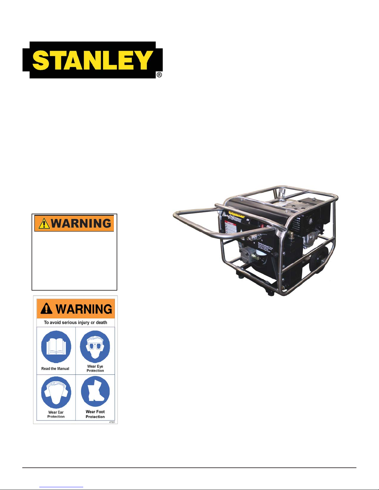
GT13
HYDRAULIC
POWER UNIT
REPAIRS AND/OR SERVICE TO
THIS TOOL MUST ONLY BE PERFORMED BY AN AUTHORIZED
AND CERTIFIED DEALER.
Copyright © 2008, The Stanley Works
68369 3/2009 Ver 2
SAFETY, OPERATION AND MAINTENANCE
USER’S MANUAL
Stanley Hydraulic Tools
3810 SE Naef Road
Milwaukie OR 97267-5698
503-659-5660
FAX 503-652-1780
www.stanleyhydraulic.com
Page 2

Page 3
TABLE OF CONTENTS
Safety Symbols .........................................................................................4
Safety Precautions ...................................................................................5
Tool Stickers & Tags .................................................................................6
Hydraulic Hose Requirements ..................................................................7
HTMA Requirements ................................................................................9
Operation ................................................................................................10
Routine Maintenance ..............................................................................14
Testing & Troubleshooting ......................................................................15
Specifi cations .........................................................................................17
Parts Lists & Illustrations ........................................................................18
Warranty .................................................................................................21
SERVICING THE STANLEY POWER UNIT: This manual contains safety, operation, and routine maintenance instructions. Stanley Hydraulic Tools recommends that servicing of hydraulic tools, other than
routine maintenance, must be performed by an authorized and certifi ed dealer. Please read the following
warning.
SERIOUS INJURY OR DEATH COULD RESULT FROM THE IMPROPER REPAIR OR SERVICE OF THIS TOOL.
REPAIRS AND / OR SERVICE TO THIS TOOL MUST ONLY BE
DONE BY AN AUTHORIZED AND CERTIFIED DEALER.
For the nearest authorized and certifi ed dealer, call Stanley Hydraulic Tools at the number listed on the
back of this manual and ask for a Customer Service Representative.
3
Page 4

SAFETY SYMBOLS
Safety symbols and signal words, as shown below, are used to emphasize all operator, maintenance and repair
actions which, if not strictly followed, could result in a life-threatening situation, bodily injury or damage to equipment.
This is the safety alert symbol. It is used to alert you to potential personal
injury hazards. Obey all safety messages that follow this symbol to avoid
possible injury or death.
This safety alert and signal word indicate an imminently hazardous situation which, if not avoided, will result in death or serious injury.
This safety alert and signal word indicate a potentially hazardous situation
which, if not avoided, could result in death or serious injury.
This safety alert and signal word indicate a potentially hazardous situation
which, if not avoided, may result in minor or moderate injury.
This signal word indicates a potentially hazardous situation which, if not
avoided, may result in property damage or damage to the equipment.
This signal word indicates a situation which, if not avoided, may result in
damage to the equipment.
Always observe safety symbols. They are included for your safety and for the protection of the tool.
LOCAL SAFETY REGULATIONS
Enter any local safety regulations here. Keep these instructions in an area accessible to the operator and maintenance personnel.
4
Page 5
SAFETY PRECAUTIONS
Tool operators and maintenance personnel must always comply with the safety precautions given in this manual and on the stickers and tags attached to the equipment.
These safety precautions are given for your safety. Review them carefully before operating the tool and before performing general maintenance or repairs.
Supervising personnel should develop additional precautions relating to the specifi c
work area and local safety regulations. If so, place the added precautions in the space
provided on page 4.
In addition to this manual, read and understand safety and operating instructions in the
Engine Operation Manual furnished with the power unit.
The GT13 Hydraulic Power Unit will provide safe and dependable service if operated in
accordance with the instructions given in this manual. Read and understand this manual
and any stickers and tags attached to the Power Unit. Failure to do so could result in
personal injury or equipment damage.
• Operator must start in a work area without bystanders. The operator must be familiar with all prohibited work areas such as
excessive slopes and dangerous terrain conditions.
• Establish a training program for all operators to ensure safe operation.
• Do not operate the power unit unless thoroughly trained or under the supervision of an instructor.
• Always wear safety equipment such as goggles, ear, head protection, and safety shoes at all times when operating the
power unit and a hydraulic tool.
• Do not inspect or clean the power unit while it is running. Accidental engagement of the unit can cause serious injury.
• Always use hoses and fi ttings rated at 2500 psi/172 bar with a 4 to 1 safety factor. Be sure all hose connections are tight.
• Be sure all hoses are connected for correct fl ow direction to and from the tool being used.
• Do not inspect hoses and fi ttings for leaks by using bare hands. “Pin-hole” leaks can penetrate the skin.
• NEVER OPERATE THE POWER UNIT IN A CLOSED SPACE. Inhalation of engine exhaust can be fatal.
• Do not operate a damaged, improperly adjusted power unit.
• Never wear loose clothing that can get entangled in the working parts of the power unit.
• Keep all parts of your body away from the working parts of the power unit.
• Keep clear of hot engine exhaust.
• Do not add fuel to the power unit while the power unit is running or is still hot.
• Do not operate the power unit if gasoline odor is present.
• Do not use fl ammable solvents around the power unit engine.
• Do not operate the power unit within 3.3 ft/1 m of buildings, obstructions or fl ammable objects.
• Do not reverse tool rotation direction by changing fl uid fl ow direction.
• Allow power unit engine to cool before storing in an enclosed space.
• Always keep critical tool markings, such as labels and warning stickers legible.
• To avoid personal injury or equipment damage, all tool repair, maintenance and service must only be performed by authorized and properly trained personnel.
5
Page 6
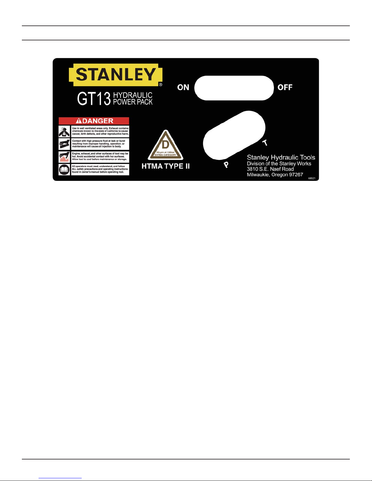
68321
Power Unit Dash Decal
TOOL STICKERS & TAGS
6
Page 7

HYDRAULIC HOSE REQUIREMENTS
HOSE TYPES
The rated working pressure of the hydraulic hose must be equal to or higher than the relief valve setting on the
hydraulic system.There are three types of hydraulic hose that meet this requirement and are authorized for use
with Stanley Hydraulic Tools. They are:
Certifi ed non-conductive - constructed of thermoplastic or synthetic rubber inner tube, synthetic fi ber
braid reinforcement, and weather resistant thermoplastic or synthetic rubber cover. Hose labeled certifi ed non-
conductive is the only hose authorized for use near electrical conductors.
Wire-braided (conductive) - constructed of synthetic rubber inner tube, single or double wire braid reinforcement, and weather resistant synthetic rubber cover. This hose is conductive and must never be used near
electrical conductors.
Fabric-braided (not certifi ed or labeled non-conductive) - constucted of thermoplastic or synthetic rubber
inner tube, synthetic fi ber braid reinforcement, and weather resistant thermoplastic or synthetic rubber cover. This
hose is not certifi ed non-conductive and must never be used near electrical conductors.
HOSE SAFETY TAGS
To help ensure your safety, the following DANGER tags are attached to all hose purchased from Stanley Hydraulic Tools. DO NOT REMOVE THESE TAGS.
If the information on a tag is illegible because of wear or damage, replace the tag immediately. A new tag may be
obtained from your Stanley Distributor.
THE TAG SHOWN BELOW IS ATTACHED TO “CERTIFIED NON-CONDUCTIVE” HOSE
D A N G E R
1 FAILURE TO USE HYDRAULIC HOSE LABELED AND CERTIFIED AS NON-CONDUCTIVE
WHEN USING HYDRAULIC TOOLS ON OR NEAR ELECTRIC LINES MAYRESULT IN DEATH
OR SERIOUS INJURY.
FOR PROPER AND SAFE OPERATION MAKE SURE THAT YOU HAVE BEEN PROPERLY
TRAINED IN CORRECT PROCEDURES REQUIRED FOR WORK ON OR AROUND
ELECTRIC LINES.
2. BEFORE USING HYDRAULIC HOSE LABELED AND CERTIFIED AS NON-CONDUCTIVE ON
OR NEAR ELECTRIC LINES. WIPE THE ENTIRE LENGTH OF THE HOSE AND FITTING
WITH A CLEAN DRY ABSORBENT CLOTH TO REMOVE DIRT AND MOSISTURE AND TEST
HOSE FOR MAXIMUM ALLOWABLE CURRENT LEAKAGE IN ACCORDANCE WITH SAFETY
DEPARTMENT INSTRUCTIONS.
DO NOT REMOVE THIS TAG
SIDE 1 SIDE 2
3
(shown smaller than actual size)
3. DO NOT EXCEED HOSE WORKING PRESSURE OR ABUSE HOSE. IMPROPER USE OR
HANDLING OF HOSE COULD RESULT IN BURST OR OTHER HOSE FAILURE. KEEP
HOSE AS FAR AWAY AS POSSIBLE FROM BODY AND DO NOT PERMIT DIRECT CONTACT
DURING USE. CONTACT AT THE BURST CAN CAUSE BODILY INJECTION AND SEVERE
PERSONAL INJURY.
4. HANDLE AND ROUTE HOSE CAREFULLY TO AVOID KINKING, ABRASION, CUTTING, OR
CONTACT WITH HIGH TEMPERATURE SURFACES. DO NOT USE IF KINKED. DO NOT USE
HOSE TO PULL OR LIFT TOOLS, POWER UNITS, ETC.
5. CHECK ENTIRE HOSE FOR CUTS CRACKS LEAKS ABRASIONS, BULGES, OR DAMAGE TO
COUPLINGS IF ANY OF THESE CONDITIONS EXIST, REPLACE THE HOSE IMMEDIATELY.
NEVER USE TAPE OR ANY DEVICE TO ATTEMPT TO MEND THE HOSE.
6. AFTER EACH USE STORE IN A CLEAN DRY AREA.
D A N G E R
DO NOT REMOVE THIS TAG
THE TAG SHOWN BELOW IS ATTACHED TO “CONDUCTIVE” HOSE.
D A N G E R
1 DO NOT USE THIS HYDRAULIC HOSE ON OR NEAR ELECTRIC LINES. THIS HOSE IS
NOT LABELED OR CERTIFIED AS NON-CONDUCTIVE. USING THIS HOSE ON OR NEAR
ELECTRICAL LINES MAY RESULT IN DEATH OR SERIOUS INJURY.
2. FOR PROPER AND SAFE OPERATION MAKE SURE THAT YOU HAVE BEEN PROPERLY
TRAINED IN CORRECT PROCEDURES REQUIRED FOR WORK ON OR AROUND
ELECTRIC LINES.
3. DO NOT EXCEED HOSE WORKING PRESSURE OR ABUSE HOSE. IMPROPER USE OR
HANDLING OF HOSE COULD RESULT IN BURST OR OTHER HOSE FAILURE. KEEP
HOSE AS FAR AWAY AS POSSIBLE FROM BODY AND DO NOT PERMIT DIRECT CONTACT
DURING USE. CONTACT AT THE BURST CAN CAUSE BODILY INJECTION AND SEVERE
PERSONAL INJURY.
4. HANDLE AND ROUTE HOSE CAREFULLY TO AVOID KINKING, CUTTING, OR CONTACT
WITH HIGH TEMPERATURE SURFACES. DO NOT USE IF KINKED. DO NOT USE HOSE TO
PULL OR LIFT TOOLS, POWER UNITS, ETC.
DO NOT REMOVE THIS TAG
SIDE 1 SIDE 2
5. CHECK ENTIRE HOSE FOR CUTS CRACKS LEAKS ABRASIONS, BULGES, OR DAMAGE TO
COUPLINGS IF ANY OF THESE CONDITIONS EXIST, REPLACE THE HOSE IMMEDIATELY.
NEVER USE TAPE OR ANY DEVICE TO ATTEMPT TO MEND THE HOSE.
6. AFTER EACH USE STORE IN A CLEAN DRY AREA.
(shown smaller than actual size)
D A N G E R
SEE OTHER SIDE
DO NOT REMOVE THIS TAG
7
Page 8

Min. Working Pressure
USE
Press/Return)
(
Certifi ed Non-Conductive Hose - Fiber Braid - for Utility Bucket Trucks
Oil Flow Hose Lengths Inside Diameter
GPM LPM FEET METERS INCH MM PSI BAR
4-9 15-34 up to 10 up to 3 3/8 10 Both 2250 155
Conductive Hose - Wire Braid or Fiber Braid -DO NOT USE NEAR ELECTRICAL CONDUCTORS
4-6 15-23 up to 25 up to 7.5 3/8 10 Both 2500 175
4-6 15-23 26-100 7.5-30 1/2 13 Both 2500 175
5-10.5 19-40 up to 50 up to 15 1/2 13 Both 2500 175
5-10.5 19-40 51-100 15-30 5/8 16 Both 2500 175
5/8 16 Pressure 2500 175
3/4 19 Return 2500 175
5-10.5 19-40 100-300 30-90
10-13 38-49 up to 50 up to 15 5/8 16 Both 2500 175
5/8 16 Pressure 2500 175
3/4 19 Return 2500 175
10-13 38-49 51-100 15-30
3/4 19 Pressure 2500 175
1 25.4 Return 2500 175
10-13 38-49 100-200 30-60
5/8 16 Pressure 2500 175
3/4 19 Return 2500 175
13-16 49-60 up to 25 up to 8
3/4 19 Pressure 2500 175
1 25.4 Return 2500 175
13-16 49-60 26-100 8-30
PRESSURE
<<< FLOW
RETURN
FLOW >>>
Typical Hose Connections
Tool to Hydraulic Circuit Hose Recom-
mendations
The chart to the right shows recommended mini-
mum hose diameters for various hose lengths
based on gallons per minute (gpm)/liters per min-
ute (lpm). These recommendations are intended
to keep return line pressure (back pressure) to a
minimum acceptable level to ensure maximum tool
performance.
This chart is intended to be used for hydraulic tool
applications only based on Stanley Hydraulic Tools
tool operating requirements and should not be used
for any other applications.
All hydraulic hose must have at least a rated
minimum working pressure equal to the maximum
hydraulic system relief valve setting.
All hydraulic hose must meet or exceed specifi -
cations as set forth by SAE J517.
8
Page 9

HTMA REQUIREMENTS
TOOL CATEGORY
HYDRAULIC SYSTEM
REQUIREMENTS TYPE I TYPEII TYPEIII TYPE RR
FLOW RATE
TOOL OPERATING PRESSURE
(at the power supply outlet)
SYSTEM RELIEF VALVE SETTING
(at the power supply outlet)
MAXIMUM BACK PRESSURE
(at tool end of the return hose)
Measured at a max. fl uid viscosity of:
(at min. operating temperature)
TEMPERATURE
Suffi cient heat rejection capacity
to limit max. fl uid temperature to:
(at max. expected ambient temperature)
Min. cooling capacity
at a temperature difference of
between ambient and fl uid temps
NOTE:
Do not operate the tool at oil temperatures above 140° F (60° C). Operation at higher temperatures can cause operator
discomfort at the tool.
4-6 gpm 7-9 gpm 11-13 gpm 9-10.5 gpm
(15-23 lpm) (26-34 lpm) (42-49 lpm) (34-40 lpm)
2000 psi 2000 psi 2000 psi 2000 psi
(138 bar) (138 bar) (138 bar) (138 bar)
2100-2250 psi 2100-2250 psi 2100-2250 psi 2200-2300 psi
(145-155 bar) (145-155 bar) (145-155 bar) (152-159 bar)
250 psi 250 psi 250 psi 250 psi
(17 bar) (17 bar) (17 bar) (17 bar)
400 ssu* 400 ssu* 400 ssu* 400 ssu*
(82 centistokes) (82 centistokes) (82 centistokes) (82 centistokes)
140° F 140° F 140° F 140° F
(60° C) (60° C) (60° C) (60° C)
3 hp 5 hp 7 hp 6 hp
(2.24 kW) (3.73 kW) (4.47 kW) (5.22 kW)
40° F 40° F 40° F 40° F
(22° C) (22° C) (22° C) (22° C)
FILTER
Min. full-fl ow fi ltration
Sized for fl ow of at least:
(For cold temp. startup and max. dirt-holding capacity)
HYDRAULIC FLUID
Petroleum based
(premium grade, anti-wear, non-conductive)
VISCOSITY
(at min. and max. operating temps)
NOTE:
When choosing hydraulic fl uid, the expected oil temperature extremes that will be experienced in service determine the
most suitable temperature viscosity characteristics. Hydraulic fl uids with a viscosity index over 140 will meet the require-
ments over a wide range of operating temperatures.
*SSU = Saybolt Seconds Universal
NOTE:
These are general hydraulic system requirements. See tool Specifi cation page for tool specifi c requirements.
25 microns 25 microns 25 microns 25 microns
30 gpm 30 gpm 30 gpm 30 gpm
(114 lpm) (114 lpm) (114 lpm) (114 lpm)
100-400 ssu* 100-400 ssu* 100-400 ssu* 100-400 ssu*
(20-82 centistokes)
9
Page 10

OPERATION
PREPARATION FOR USE
Do not operate the power unit until you have read the
engine operating and maintenance instructions manual
furnished with the unit.
1. ENGINE CRANKCASE OIL LEVEL
Always check the engine oil level before starting the en-
gine. Make sure the oil level is at the FULL MARK on the
dipstick. Do not overfi ll. Use 4-stroke motor oil that meets
or exceeds the requirements for API service classifi cations
SJ or later as specifi ed in the engine operating and mainte-
nance manual. Refer to the engine manual for oil viscosity
grade.
2. ENGINE FUEL LEVEL
Check the fuel level. If low, fi ll with un-leaded gasoline with
a minimum of pump octane of 86 or higher or a research
octane of 91 or higher. Refer to the engine manual for for
details.
3. HYDRAULIC FLUID
These fl uids are recommended by Stanley. Other fl uids
that meet or exceed the specifi cations of these fl uids may
also be used.
Chevron AW-MV -32
Exxon "Univis" J-26
Mobil D.T.E. 13
Gulf "Harmony" AW-HVI-150-32
Shell "Tellus" T-32
Texaco "Rando" HD-AZ
Union "Unax" AW-WR-32
Terresolve EnviroLogic 132
4. HYDRAULIC CONNECTIONS
The recommended hose length is 25 ft/8 m with a 1/2
inch/12.7 mm inside diameter. The hoses must have a
working pressure rating of at least 2500 psi/175 bar. Each
hose end must have male thread ends compatible with
H.T.M.A. (HYDRAULIC TOOL MANUFACTURERS ASSOCIATION) quick disconnect fi ttings (NPT type threads).
(See Figure 2.)
Check the sight gauge on the hydraulic fl uid reservoir for
the proper fi uid level. Use fl uids meeting the following
specifi cations.
Viscosity (Fluid Thickness)
U.S. METRIC
50°F 450 SSU Maximum 10°C 95 C.S.
100°F 130-200 SSU 38°C 27-42 C.S.
140°F 85 SSU Minimum 60°C 16.5 C.S. Min
Pour Point -10°F/-23°C Minimum (for cold startup)
Viscosity Index (ASTM D-2220) 140 Minimum
Demulsibility (ASTM D-1401) 30 Minutes Maximum
Flash Point (ASTM D-92) 340°F/171°C Minimum
Rust Inhibition (ASTM D-665 A & B) Pass
Oxidation (ASTM D-943) 1000 Hours Minimum
Pump Wear Test (ASTM D-2882) 60 mg Maximum
The following fl uids work well over a wide temperature
range, allow moisture to settle out and resist biological
growth that may occur in cool operating hydraulic circuits.
Figure 1. Panel Control Valve
Facing the panel control valve, the bottom male quick
disconnect fi tting is the PRESSURE FLUID OUT fi tting. The
top female quick disconnect fi tting is the RETURN FLUID
IN fi tting.
QUICK DISCONNECT COUPLERS
H.T.M.A. approved quick disconnect couplings are installed
to hydraulic hoses so that the direction of oil fl ow is always
from the male to the female quick disconnect as shown in
fi gure 2. Quick disconnect couplings and hose fi ttings are
selected so that additional fi ttings such as reducer or adapt-
er fi ttings are not required.
If adapter fi ttings are used, they must be approved steel
hydraulic fi ttings meeting a minimum operating pressure
rating of 2500 psi/172 bar. Do not use galvanized pipe fi t-
tings or black pipe fi ttings.
DO NOT OVERTIGHTEN THE FITTINGS.
10
Page 11

OPERATION
CONTROL PANEL
PRESSURE
H.T.M.A. 1/2 INCH FE-
MALE QUICK DISCON-
NECT COUPLER
H.T.M.A. 1/2 INCH MALE
QUICK DISCONNECT
COUPLER
1/2 INCH MALE PIPE HOSE END
1/2 INCH I.D. HOSE, 25 FT
LONG WITH 2500 PSI/
172 BAR RATING AND
4 TO 1 SAFETY FACTOR
CONTROLS
The Power Unit provides one circuit, with an oil fl ow of 7
gpm/26 lpm up to 2000 psi/140 bar.
RETURN
Figure 3. Panel and Control Lever
One hydraulic tool can be connected to the tool circuit. The
circuit is activated by moving the control lever to the "ON"
position.
THROTTLE CONTROL
The Power Unit is equipped with an automatic throttle control that permits the operator to select one of 2 operating
modes—automatic throttle or manual throttle. See fi gure 4.
PRESSURE
1/2 INCH MALE PIPE HOSE END
ADAPTER, 3/8 INCH MALE PIPE x
PRESSURE
H.T.M.A. 1/2 INCH FE-
MALE QUICK DISCON-
NECT COUPLER
H.T.M.A. 1/2 INCH MALE
QUICK DISCONNECT
-8 SAE O-RING
TOOL
COUPLER
RETURN
RETURN
Knob
Figure 4. Throttle Control Knob
Automatic throttle Control
In this mode, engine speed varies with hydraulic circuit
pressure during tool use to maintain a constant 7 gpm/26
lpm. When a tool is not being used the engine will return to
idle automatically.
Automatic Throttle Control is set by positioning the adjustment knob (shown in fi gure 4) to the far right and tightening
it to maintain its position.
Manual Throttle Control
In this mode, engine speed is manually held at full throttle
to maintain 7 gpm/26 lpm. When a tool is not being used
the engine will not return to idle until the manual setting is
removed.
Figure 2. Hydraulic Connections
Typical conditions requiring the manual throttle control are:
11
Page 12

OPERATION
• When operating drills or grinders or pumps, tool rpm
must be maintained even when load requirements are
light.
START-UP
Manual Throttle Control is set by positioning the knob
(shown in fi gure 4.) to the far left and tightening it to main-
tain its position.
Shown above in Figure 5 are the primary engine components referred to in this section. Become familiar with these
components and read and understand the engine operation
and maintenance manual before starting the engine and
operating the power unit for the fi rst time.
Before starting the engine, make sure the throttle
control knob is set for "Auotmatic Throttle Control".
START-UP
1. Check the engine oil level.
2. Check the hydraulic oil level.
Figure 5. Engine Components
3. Check that the engine fuel tank is full.
Explosion and fi re hazard.
Checking the engine fuel level or refueling the engine
when it is hot or running can result in an explosion
and/or fi re that may result in death or serious injury.
Do not remove the fuel cap while the engine is running
or. Do not add fuel to the tank while the engine is hot.
Do not fi ll the fuel tank to a point of overfl owing.
4. Ensure the automatic throttle control knob is set to the
"automatic throttle" position.
12
Page 13

OPERATION
5. Move the choke lever to the CLOSED position as shown
in fi gure 6.
Figure 6. Choke Lever
6. Move the fuel valve lever to the ON position as shown in
fi gure 7.
and 10.
11. Set the throttle control for "automatic" or "manual"
operation.
12.Move the tool circuit control lever to the ON position.
When fi nished operating the tool, move the tool circuit con-
trol lever to the OFF positon.
COLD WEATHER STARTUP
1. Use the procedures described under "STARTUP" and
then follow the procedure below.
2. Hydraulic fl uids are thicker in cold weather. Therefore,
it is recommended that the engine be run at low idle long
enough to bring the fl uid temperature up to a minimum of
50°F/10°C.
3. If the tools and tool hoses are cold, it is recommended
to allow hydraulic fl uid to circulate through the tool hoses
until warm before using the tool.
Figure 7. Fuel Lever
7. Position the engine ON-OFF switch to the ON position
as shown in fi gure 8.
Figure 8. ON-OFF Switch
8. Pull the starter grip on the recoil starter until you feel
resistance. Then pull fi rmly upward. Do not allow the starter
grip to snap back against the engine. Return it gently.
SHUTDOWN
1. Ensure the tool circuit control lever is in the OFF position.
2. Unless already at idle the power unit should return to
idle if operating in the "automatic" mode. If operating in
the manual mode, move the knob to the far right position
and tighten it to maintain its position.
3. Allow the engine to idle for approximately one minute
and move the engine switch to the OFF position.
9. After the engine starts, allow it to warm up. Gradually
adjust the choke until it is in the open position.
10. Connect hoses and the tool as desrcribed on pages 9
13
Page 14

ROUTINE MAINTENANCE
ENGINE MAINTENANCE
Follow the maintenance schedule and general maintenance
instructions in the engine maintenance and operation
manual furnished with the power unit.
HYDRAULIC SYSTEM MAINTENANCE
• Check hydraulic fl uid level daily. Add fl uid per specifi ca-
tions in this manual. (See "HYDRAULIC FLUID" under the
section titled "OPERATING INSTRUCTIONS".
• Remove condensed moisture from the hydraulic
fl uid by pumping the hydraulic fl uid into a 5 gal/20 l con-
tainer through the pressure hose. Make sure the engine is
at idle when performing this procedure. When the hydraulic
reservoir is empty turn the engine off immediately.
• Allow the fl uid to sit long enough for the water to settle to
the bottom of the container. Slowly pour the fl uid back into
the hydraulic tank, avoiding the water at the bottom of the
container.
• Each day, check hydraulic lines and fi ttings for leaks,
kinks, etc. Do not use your hand to perform this check.
STORAGE
• Clean the unit thoroughly before storage. Do not use
water pressure.
• Always store the unit in a clean and dry facility.
• If the unit will be stored for a prolonged period (over 30
days), add a fuel additive to the fuel tank to prevent the fuel
from gumming. Run engine for a short period to circulate
the additive.
• Replace crankcase oil with new oil.
• Remove the spark plug and pour approximately 1 ounce
(30 ml) of engine oil into the cylinder. Replace the spark
plug and crank the engine slowly to distribute the oil.
• Check hydraulic reservoir for water. If water is found,
change the oil and circulate it through the tool hose and
tool. (See "HYDRAULIC SYSTEM MAINTENANCE" earlier
in this section).
• Change the hydraulic fi lter element every 200 hours of
operation. Change more often if cold, moist or dusty conditions exist.
• Check oil cooler for debris. Remove debris with air pressure.
14
Page 15

TESTING & TROUBLESHOOTING
GENERAL
4. Start the engine and allow it to run until warm.
Tests and adjustments should be performed periodically to
ensure the power unit is operating at maximum effi ciency.
Stanley Circuit Tester (part number 04182) is recommended. This tester can be used to isolate problems in both the
engine and hydraulic system prior to any power unit disassembly.
TESTING THE HYDRAULIC CIRCUIT
The following tests can be performed to ensure that the
hydraulic pump is supplying the correct fl ow and pressure
and that the system relief valve is operating properly.
During these tests, make sure the engine is warm and operating smoothly. If test results are not as specifi ed, refer to
the troubleshooting table in this section for possible causes.
TESTING THE 7 GPM HTMA TYPE 1 CIRCUIT
To test the circuit, proceed as follows:
1. Set the throttle control knob to the automatic position.
2. Connect the Stanley Circuit Tester across the hose ends
(where the tool would normally be connected).
3. Fully open the tester restrictor valve (counterclockwise).
5. With the engine at full operating speed, the test fl ow
gauge should read 7 gpm/26 lpm.
6. Slowly turn the restrictor valve clockwise while watching
the pressure gauge. The fl ow rate should stay at 7 gpm/26
lpm as the pressure gauge reaches 2100-2200 psi/148-155
bar.
7. At 2100-2200 psi/148-155 bar, the relief valve should
begin to open. The pressure at which the relief valve just
begins to open is commonly referred to as the "cracking
pressure". At the "cracking pressure," the fl ow rate should
start to drop because the relief valve is allowing fl uid to by-
pass to the hydraulic reservoir. The "cracking pressure" is
preset at the factory and if it is not within the above range,
the relief valve must be re-set as follows:
a. The relief valve is located behind the dash panel in the
manifold assembly. Use an open end or box end wrench to
loosen the nut on the relief valve.
b. Use an Allen wrench to adjust the relief valve. Turn
clockwise to raise the pressure and counterclockwise to
reduce the pressure.
c. Tighten the nut and retest.
15
Page 16

TROUBLESHOOTING
PROBLEM CAUSE REMEDY
Engine will not start. No fuel. Add Fuel.
Fuel fi lter plugged. Replace fuel fi lter.
Defective spark plug. Remove plug, check gap, clean or
replace.
Fluid blowing out of fl uid Hydraulic tank overfi lled. Correct the fl uid level.
reservoir vent.
Pump suction leak. Check suction connections. Tighten if
necessary.
Hydraulic tool won't operate. Incorrect hose connection to Make sure the tool hose circuit goes
tool. from left (pressure) fi tting to tool
and back to the right fi tting (return).
Fluid always fl ows from the male to
female fi ttings.
Quick disconnect fi ttings Detach from hose, connect set
defective. together and check for free fl ow.
Hydraulic fl uid level low. Check for correct fl uid level. Fill
using the recommended fl uid.
Pump coupling defective. With the engine not running.
Check the coupling between the pump
and engine that it is engaged and is
not damaged. Caution: Keep hands
clear of rotating objects.
Relief valve stuck open. Adjust or replace valve.
Suction hose kinked. Make sure suction hose from fl uid
reservoir to pump inlet has a smooth
curve.
Tool is defective. Refer to tool manual.
16
Page 17

SPECIFICATIONS
Engine: ...............................................................................................................................................Honda GX390 4 stroke
Horsepower .........................................................................................................................................................................11
Capacity......................................................................................................................................... One 7 gpm/26 lpm Circuit
Length:.......................................................................................................................................................26.25 in. / 66.7 cm
Width: ........................................................................................................................................................20.75 in. / 52.7 cm
Height: ..........................................................................................................................................................21.25 in. / 54 cm
Weight (Wet): ...................................................................................................................................162 lb / 73.5 kg
Fuel Tank Capacity: ........................................................................................................... .............................1.6 gal. / 6.1 ltr
Hydraulic Reservor Capacity: .......................................................................................................................... 1.5 gal / 5.7 ltr
Relief Valve "crack" setting ........................................................................................................................ 2150 psi / 145 bar
Full relief setting ........................................................................................................................................ 2400 psi / 172 bar
HTMA/EHTMA Category .................................................................................. Flow Rate 7 gpm / 26 lpm
..............................................................................................................Nominal Pressure 1500 psi / 103 bar
....................................................................................................................Max Pressure 2150 psi / 138 bar
Vibration Level .................................................................................................................................................................. N/A
17
Page 18

GT13 PARTS ILLUSTRATION
Location of Automatic Throttle
Bracket
18
Page 19

GT13 PARTS ILLUSTRATION CONTINUED
Engine mounting
Wheel to Frame Placement
19
Page 20

GT13 PARTS LIST
Item Part No. Qty Description
1 68355 1 Hose Assy
2 02633 1 Knob
3 67329 1 Hose Assy
4 350036 1 Elbow
5 60774 2 Clamp
6 68212 1 Sight Gauge
7 67289 1 Oil Reservoir
8 67285 1 Valve Manifold
9 00856 1 Connector, Straight Thread
10 58857 1 Coupler, Male
11 58856 1 Coupler, Female
12 67308 1 Filter
13 67313 1 Elbow
14 59131 1 Relief Valve
15 12787 4 Nut
16 67318 1 Hose Barb
17 67354 1 Bracket Weldment
18 60945 11 Washer
19 59074 11 Capscrew
20 60962 3 Capscrew
21 67288 1 Blower Housing
22 23530 4 Bolt, Hex Flange
23 59075 3 Bolt, Hex Flange
24 26831 3 Washer
25 67327 1 Hose
26 67610 4 Clamp
27 67313 1 Elbow
28 04864 1 Adapter
29 00145 4 Washer
30 00144 4 Capscrew
31 67292 1 Hydraulic Pump
32 67319 1 Elbow
33 67287 1 Oil Cooler
34 67328 1 Hose Assy
35 67507 1 Guard Weldment
36 67511 1 Rubber Mount
37 67510 1 Reaction Plate
38 08667 6 Screw
39 56690 1 Inlet Ring
40 08669 1 Gasket
41 60953 4 Capscrew
42 67291 1 Pump Adapter
43 06180 1 Capscrew
44 67294 1 Washer
45 67290 1 Coupler
46 08035 1 Blower Wheel
47 68299 1 Cylinder Assy (Incld Items 57-65)
48 07819 1 Key
49 67284 1 Engine, Honda GX390QA2
50 68367 1 Bracket Weldment
51 68304 1 Tube Clamp
52 68346 1 Throttle Lever
53 68354 1 Roll Pin
54 68368 1 Bracket
55 68345 1 Knob
Item Part No. Qty Description
56 68353 2 Capscrew
57 67464 1 Rod End
58 68324 1 Nut
59 00026 1 O-ring
60 67541 1 Cap
61 01605 1 O-ring
62 67463 1 Cylinder
63 67466 1 Rod
64 67467 1 Spring
65 67469 1 Adapter
66 04860 1 Elbow
67 67286 1 Adapter
68 67594 1 Cap
69 68174 1 Dash Panel
70 68176 2 Bumper
71 59074 4 Capscrew
72 68321 1 Sticker, Dash
73 68357 2 Capscrew
74 59095 6 Nut, Flange
75 68187 4 Washer, Nylon
76 03906 3 Nut
77 68170 1 Handle
78 40435 2 Bolt, Flange
79 No Item
80 68177 2 Wheel
81 68184 2 Axle
82 09210 2 Nut
83 68178 1 Lower Frame Weldment
84 18893 6 Nut, Flange
85 21713 2 Bumper
86 24282 2 Capscrew
87 68356 2 Capscrew
88 40433 2 Bolt, Flange
89 68157 1 Upper Frame Weldment
90 68175 1 Lift Bracket
91 370502 1 Capscrew
92 68515 1 Rod
93 68396 1 Handle Hub
94 22674 1 Set Screw
95 23399 1 Backup Ring
96 51184 1 Cap Screw
97 49159 1 Lockwasher
98 68518 1 Nut
99 00596 2 Capscrew
20
Page 21

WARRANTY
Stanley Hydraulic Tools (hereinafter called “Stanley”), subject to the exceptions contained below, warrants new hydraulic tools for a period of one year from the date of sale to
the fi rst retail purchaser, or for a period of 2 years from the shipping date from Stanley, whichever period expires fi rst, to be free of defects in material and/or workmanship at
the time of delivery, and will, at its option, repair or replace any tool or part of a tool, or new part, which is found upon examination by a Stanley authorized service outlet or by
Stanley’s factory in Milwaukie, Oregon to be DEFECTIVE IN MATERIAL AND/OR WORKMANSHIP.
EXCEPTIONS FROM WARRANTY
NEW PARTS: New parts which are obtained individually are warranted, subject to the exceptions herein, to be free of defects in material and/or workmanship at the time
of delivery and for a period of 6 months after the date of fi rst usage. Seals and diaphragms are warranted to be free of defects in material and/or workmanship at the time
of delivery and for a period of 6 months after the date of fi rst usage or 2 years after the date of delivery, whichever period expires fi rst. Warranty for new parts is limited to
replacement of defective parts only. Labor is not covered.
FREIGHT COSTS: Freight costs to return parts to Stanley, if requested by Stanley for the purpose of evaluating a warranty claim for warranty credit, are covered under this
policy if the claimed part or parts are approved for warranty credit. Freight costs for any part or parts which are not approved for warranty credit will be the responsibility of the
individual.
SEALS & DIAPHRAGMS: Seals and diaphragms installed in new tools are warranted to be free of defects in material and/or workmanship for a period of 6 months after the
date of fi rst usage, or for a period of 2 years from the shipping date from Stanley, whichever period expires fi rst.
CUTTING ACCESSORIES: Cutting accessories such as breaker tool bits are warranted to be free of defects in material and or workmanship at the time of delivery only.
ITEMS PRODUCED BY OTHER MANUFACTURERS: Components which are not manufactured by Stanley and are warranted by their respective manufacturers.
a. Costs incurred to remove a Stanley manufactured component in order to service an item manufactured by other manufacturers.
ALTERATIONS & MODIFICATIONS: Alterations or modifi cations to any tool or part. All obligations under this warranty shall be terminated if the new tool or part is altered or
modifi ed in any way.
NORMAL WEAR: any failure or performance defi ciency attributable to normal wear and tear such as tool bushings, retaining pins, wear plates, bumpers, retaining rings and
plugs, rubber bushings, recoil springs, etc.
INCIDENTAL/CONSEQUENTIAL DAMAGES: To the fullest extent permitted by applicable law, in no event will STANLEY be liable for any incidental, consequential or special
damages and/or expenses.
FREIGHT DAMAGE: Damage caused by improper storage or freight handling.
LOSS TIME: Loss of operating time to the user while the tool(s) is out of service.
IMPROPER OPERATION: Any failure or performance defi ciency attributable to a failure to follow the guidelines and/or procedures as outlined in the tool’s operation and
maintenance manual.
MAINTENANCE: Any failure or performance defi ciency attributable to not maintaining the tool(s) in good operating condition as outlined in the Operation and Maintenance
Manual.
HYDRAULIC PRESSURE & FLOW, HEAT, TYPE OF FLUID: Any failure or performance defi ciency attributable to excess hydraulic pressure, excess hydraulic back-pres-
sure, excess hydraulic fl ow, excessive heat, or incorrect hydraulic fl uid.
REPAIRS OR ALTERATIONS: Any failure or performance defi ciency attributable to repairs by anyone which in Stanley’s sole judgement caused or contributed to the failure
or defi ciency.
MIS-APPLICATION: Any failure or performance defi ciency attributable to mis-application. “Mis-application” is defi ned as usage of products for which they were not originally
intended or usage of products in such a matter which exposes them to abuse or accident, without fi rst obtaining the written consent of Stanley. PERMISSION TO APPLY ANY
PRODUCT FOR WHICH IT WAS NOT ORIGINALLY INTENDED CAN ONLY BE OBTAINED FROM STANLEY ENGINEERING.
WARRANTY REGISTRATION: STANLEY ASSUMES NO LIABILITY FOR WARRANTY CLAIMS SUBMITTED FOR WHICH NO TOOL REGISTRATION IS ON RECORD. In
the event a warranty claim is submitted and no tool registration is on record, no warranty credit will be issued without fi rst receiving documentation which proves the sale of
the tool or the tools’ fi rst date of usage. The term “DOCUMENTATION” as used in this paragraph is defi ned as a bill of sale, or letter of intent from the fi rst retail customer. A
WARRANTY REGISTRATION FORM THAT IS NOT ALSO ON RECORD WITH STANLEY WILL NOT BE ACCEPTED AS “DOCUMENTATION”.
NO ADDITIONAL WARRANTIES OR REPRESENTATIONS
This limited warranty and the obligation of Stanley thereunder is in lieu of all other warranties, expressed or implied including merchantability or fi tness for a particular purpose
except for that provided herein. There is no other warranty. This warranty gives the purchaser specifi c legal rights and other rights may be available which might vary depend-
ing upon applicable law.
21
Page 22

Stanley Hydraulic Tools
3810 SE Naef Road
Milwaukie, Oregon
503-659-5660 / Fax 503-652-1780
www.stanleyhydraulic.com
 Loading...