

Page 1
CUIDADO Y MANTENIMIENTO
Almacenamiento
• Almacene la unidad en un lugar limpio, seco, fresco cuando es parado.
• Limpie la cubierta y las cuerdas de la unidad (cuanto sea necesario) con un paño seco (o levemente húmedo). Asegúrese de que la
unidad sea totalmente disconnected de la batería y de la fuente de energía antes de limpiar.
• Para mantener la condición de funcionamiento y maximizar la vida de las cuerdas del cargador, arróllelas siempre libremente para
el almacenaje. No los prense con una venda apretada.
ACCESORIOS
Los accesorios que se recomiendan para la herramienta están disponibles en su distribuidor local. Si necesita asistencia en relación
con los accesorios, por favor contacto fabricante en (877) 571-2391.
ADVERTENCIA: El uso de cualquier accesorio no recomendado para el uso con esta aplicación podía ser peligroso.
INFORMACIÓN DE SERVICIO
Si usted necesita asesoramiento técnico, reparación, o una verdadera fábrica piezas de recambio, contacto con el fabricante en (877)
571-2391.
UNA GARANTÍA LIMITADA DEL AÑO
El fabricante garantiza este producto contra defectos en materiales y mano de obra durante un período de UN (1) AÑO desde la
fecha de compra por el usuario final comprador (“período de Garantía”).
Si hay un defecto y una reclamación válida es recibido dentro del periodo de garantía, el producto defectuoso puede ser
reemplazado o reparado en las siguientes maneras: (1) Devolver el producto al minorista donde producto fue comprado por
un intercambio (siempre que la tienda es una participación minorista). Regresa al minorista debe hacerse dentro del plazo del
minorista, política de retorno de intercambios sólo (generalmente de 30 a 90 días después de la venta). Prueba de compra puede
ser necesaria. Por favor consulte con el minorista para su regreso específicas política sobre rendimientos que están fuera del plazo
establecido para el intercambio. (2) Devolver el producto al fabricante de reparación o sustitución de fabricante, opción. Prueba de
compra puede ser requerida por el fabricante.
Esta garantía no se aplicará a los accesorios, bulbos, fusibles y baterías; defectos resultantes de desgaste normal; accidentes; daños
y perjuicios sufridos durante el envío; alteraciones; el uso no autorizado o reparación; abandono; mal uso; abuso; y no seguir las
instrucciones de cuidado y mantenimiento del producto.
Esta garantía le da, el original comprador minorista, determinados derechos jurídicos y puede tener otros derechos que varían de
estado a estado o provincia a provincia. Este producto no está destinado para uso comercial.
Termine por favor la tarjeta de registro del producto y vuelva en el plazo de 30 días de la compra del producto a: Baccus Global LLC,
595 S. Federal Highway, Suite 210, Boca Raton, FL 33432. Baccus Global LLC, discado gratuito: (877) 571-2391.
ESPECIFICACIONES
Entrada: 120 VCA, 60 Hz, 650 vatios
Output: 6 VCC/12VCC/24VCC, 20A
36VCC, 12A
48VCC, 10A
GBCPRO
Vehicle and Golf cart Battery charGer
instruction Manual
carGador de Bateria Para Vehiculos y
carros de Golf
Manual de instrucción
Importados por
Baccus Global LLC
595 S. Federal Highway, Suite 210
Boca Raton, FL 33432
(877) 571-2391
RD011411
English page 2
Español pagina 15
SAVE THIS INSTUCTION MANUAL FOR FUTURE REFERENCE.
CONSERVE ESTE MANUAL PARA FUTURAS CONSULTAS.
© 2010 Baccus Global LLC
Boca Raton, FL 33432
Customer Service: (877) 571-2391
128
Page 2
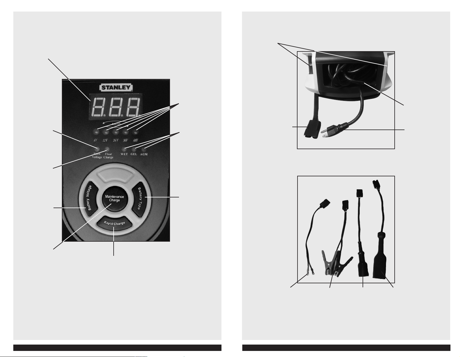
FEATURES
3CHARACTER DIGITAL DISPLAY
SHOW VOLTAGE
INDIC ATOR
FLOAT CHARGE
INDIC ATOR
BATTERY VOLTAGE
BUTTON
BATERY VOLTAGE
INDIC ATOR
BATTERY TYPE
INDIC ATOR
BATTERY TYPE
SELEC TOR BUTTON
BATTERY CLAMPS
STORAGE COMPARTMENT
CHARGER CONNEC TOR
CONNECTS TO
ORINGS, BATTERY
CLAMPS, ROUND
CART CONNECTOR OR
RECTANGULAR CART
CONNEC TOR
AC CORD STORAGE
COMPARTMENT
120 VOLT AC PLUG
MAINTENANCE
CHARGE BUTTON
RAPID CHARGE
BUTTON
ORINGS BATTERY
CLAMPS
FOR USE WITH
6V, 12V, OR 24V
BATTERIE S ONLY
ROUND CART
CONNEC TOR
32
RECTANGULAR
CART
CONNEC TOR
Page 3
This device complies with part 15 of the FCC rules. Operation is subject to the following two conditions: (1) this device may
not cause harmful interference, and (2) this device must accept any interference received, including interference that may
cause undesired operation.
This equipment has been tested and found to comply with the limits for a Class B digital device, pursuant to part 15 of
the FCC Rules. These limits are designed to provide reasonable protection against harmful interference in a residential
installation. This equipment generates, uses and can radiate radio frequency energy and, if not installed and used in
accordance with the instructions, may cause harmful interference to radio communications. However, there is no guarantee
that interference will not occur in a particular installation. If equipment does cause harmful interference to radio or
television reception, which can be determined by turning the equipment off and on, the user is encouraged to try to correct
the interference by one or more of the following measures:
• Reorient or relocate the receiving antenna.
• Increase the separation between equipment and receiver.
• Connect the equipment into an outlet on a circuit different from that to which the receiver is connected.
• Consult the dealer or an experienced radio/TV technician for help.
Changes or modifications not approved by the party responsible for compliance could void user’s authority to operate the
equipment.
GENERAL SAFETY WARNINGS AND INSTRUCTIONS
READ ALL INSTRUCTIONS
WARNING: Read all instructions before operating battery charger. Failure to follow all instructions listed below may
result in electric shock, fire and/or serious injury.
SAFETY GUIDELINES / DEFINITIONS
DANGER: Indicates an imminently hazardous situation which, if not avoided, will result in death or serious injury.
WARNING: Indicates a potentially hazardous situation which, if not avoided, could result in death or serious injury.
CAUTION: Indicates a potentially hazardous situation which, if not avoided, may result in minor or moderate injury.
CAUTION: Used without the safety alert symbol indicates potentially hazardous situation which, if not avoided, may result in
property damage.
RISK OF UNSAFE OPERATION. When using tools or equipment, basic safety precautions should always be followed to reduce the
risk of personal injury. Improper operation, maintenance or modification of tools or equipment could result in serious injury and
property damage. There are certain applications for which tools and equipment are designed. Manufacturer strongly recommends
that this product NOT be modified and/or used for any application other than for which it was designed. Read and understand all
warnings and operating instructions before using any tool or equipment.
Extension cords
WARNING: An extension cord should not be used unless absolutely necessary. Use of improper extension cord could result in a
risk of fire and electric shock. If an extension cord is used, make sure that the pins of the extension cord are the same number, size
and shape as those in the charger.
Make sure your extension cord is in good condition. When using an extension cord, be sure to use one heavy enough to carry the
current your product will draw. An undersized cord will cause a drop in line voltage resulting in loss of power and overheating. The
following table shows the correct size to use depending on cord length and nameplate ampere rating. If in doubt, use the next
heavier gage. The smaller the gage number, the heavier the cord.
Recommended Minimum AWG Size for Extension Cords for Battery Chargers
AC Input Rating American Wire Gage (AWG) Size of Cord
Amperes Length of Cord, feet (m)
Equal to or But less
greater than than
0 2 18 18 18 16
2 3 18 18 16 14
3 4 18 18 16 14
4 5 18 18 14 12
5 6 18 16 14 12
6 8 18 16 12 10
8 10 18 14 12 10
10 12 16 14 10 8
12 14 16 12 10 8
14 16 16 12 10 8
Power Cord Safety
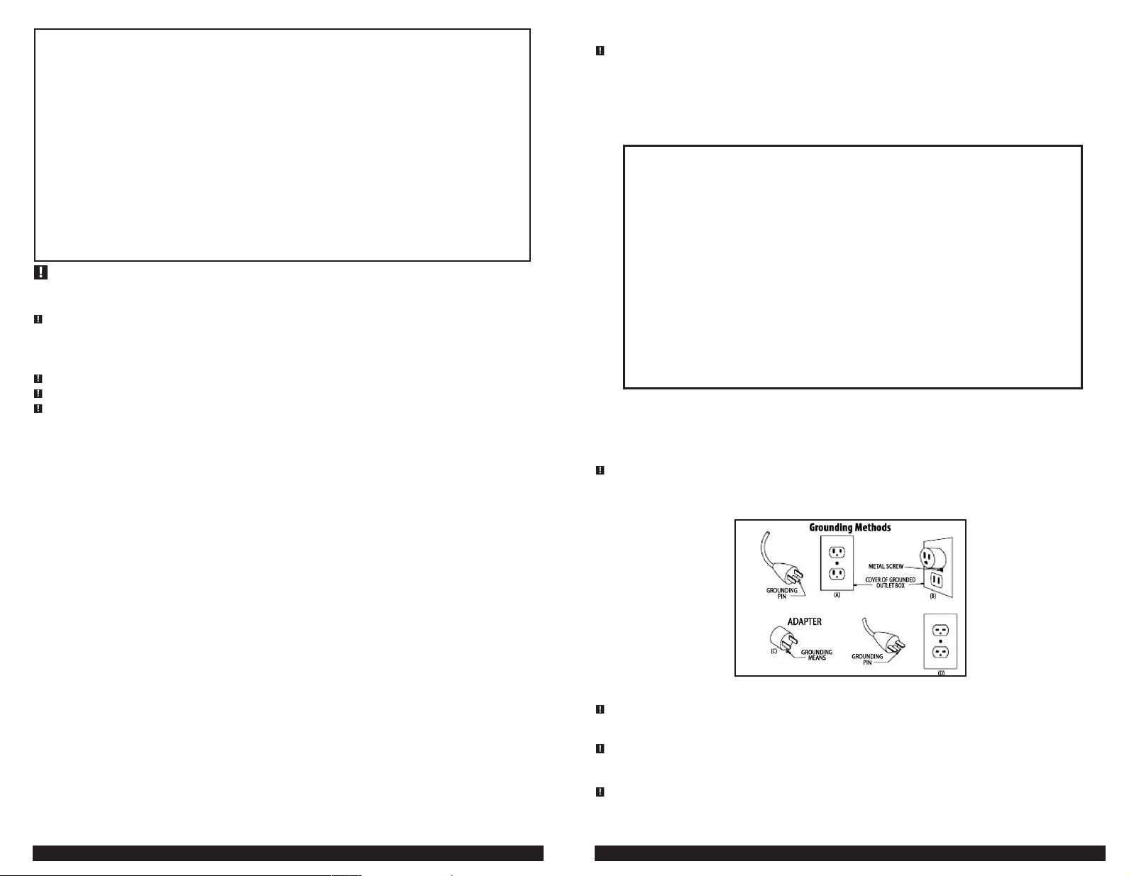
This battery charger is for use on a nominal 120-volt circuit, and has a grounding plug that looks like the plug illustrated in sketch A
in the illustration below. A temporary adapter, which looks like the adapter illustrated in sketches B and C, may be used to connect
this plug to a two-pole receptacle as shown in sketch B if a properly grounded outlet is not available. The temporary adapter should
be used only until a properly grounded outlet can be installed by a qualified electrician.
ear or lug extending from adapter must be connected to a properly grounded outlet– make certain it is grounded. If necessary,
replace original outlet cover plate screw with a longer screw that will secure adapter ear or lug to outlet cover plate and make
ground connection to grounded outlet.
16 18 14 12 8 8
18 20 14 12 8 6
DANGER: Before using adapter as illustrated, be certain that center screw of outlet plate is grounded. The green-colored rigid
25 (7.6) 50 (15.2) 100 (30.5) 150 (45.6)
IMPORTANT SAFETY INSTRUCTIONS
• This unit was designed for household use only.
• Avoid dangerous environments. Don’t use battery chargers in damp or wet locations.
• Keep children away. Keep away from children. This is not a toy!
• Store indoors. When not in use, battery chargers should be stored indoors in dry, and high or locked-up places – out of reach
of children.
• Unplug the battery charger when not in use.
• Check unit periodically for wear and tear. Take to a qualified technician for replacement of worn or defective parts
immediately.
• Read and understand this instruction manual before using this unit.
• FIRST AID – SKIN: If battery acid comes in contact with skin, rinse immediately with water, then wash thoroughly with soap and
water. If redness, pain, or irritation occurs, seek immediate medical attention.
EYES: If battery acid comes in contact with eyes, flush eyes immediately, for a minimum of 15 minutes and seek immediate
medical attention.
SPECIFIC SAFETY INSTRUCTIONS FOR POWER CORDS
• Don’t abuse cord. Never carry appliance by cord or yank it to disconnect from receptacle. Keep cord from heat, oil, and sharp
edges. Pull cord by plug rather than cord when unplugging the unit.
• Ground Fault Circuit Interrupter (GFCI) protection should be provided on the circuits or outlets to be used. Receptacles are
available having built in GFCI protection and may be used for this measure of safety.
4 54
SPECIFIC SAFETY INSTRUCTIONS FOR BATTERY CHARGERS
DANGER: To avoid the risk of explosion and serious injury, NEVER connect this battery charger to a bank of
batteries with cells or batteries of different voltages. ALL batteries within a bank of batteries to be charged must be
the same voltage.
WARNING: BURST HAZARD: Do not use the unit for charging dry-cell batteries that are commonly used with home appliances.
These batteries may burst and cause injury to persons and damage property. It is not intended to supply power to a low-voltage
electrical system other than in a starter-motor application.
WARNING: TO REDUCE THE RISK OF ELECTRIC SHOCK:
• Do not expose charger or components to water or any other liquid; or use charger in the rain or snow.
• Never immerse the battery charger in water or any other liquid, or use when wet.
Page 4

WARNING: RISK OF EXPLOSIVE GASES:
• Working in the vicinity of a lead acid battery is dangerous. Batteries generate explosive gases during normal battery operation.
For this reason, it is of the utmost importance that each time before using the battery charger you read this manual and follow
instructions exactly.
• To reduce the risk of battery explosion, follow these instructions and those published by the battery manufacturer and
manufacturer of any equipment you intend to use in the vicinity of the battery. Review cautionary markings on these products
and on the engine.
• This equipment employs parts (switches, relays, etc.) that produce arcs or sparks. Therefore, if used in a garage or enclosed area,
the unit MUST be placed not less than 18 inches above the floor.
• THIS UNIT IS NOT FOR USE BY CHILDREN AND SHOULD ONLY BE OPERATED BY ADULTS.
WARNING: TO REDUCE THE RISK OF FIRE:
• Do not operate near flammable materials, fumes or gases.
• Do not expose to extreme heat or flames.
Any of these actions may cause serious electrical damage and/or a fire.
CAUTION: TO AVOID PROPERTY DAMAGE: Never use the battery clamps for charging 36V or 48V batteries. Battery
Clamps are for use in 6V, 12V and 24V batteries; and 8V batteries in a battery group totaling 24V* only. Use the O-ring
or quick connectors for 36 and 48 volt batteries or battery groups. *Not for use on individual 8V batteries.
• Use of accessories and attachments: The use of any accessory or attachment not recommended by manufacturer for use with
this battery charger could be hazardous.
• Stay alert. Use common sense. Do not operate battery charger when you are tired.
• Check for damaged parts. Any part that is damaged should be properly repaired or replaced by an authorized service center
unless otherwise indicated elsewhere in this instruction manual before further use.
• Do not operate the battery charger near flammable liquids or in gaseous or explosive atmospheres. Switches and relays may
spark, and the sparks might ignite fumes.
CAUTION: TO REDUCE THE RISK OF INJURY OR PROPERTY DAMAGE:
• NEVER ATTEMPT TO CHARGE A FROZEN BATTERY.
• Vehicles that have on-board computerized systems may be damaged if vehicle battery is charged. Before charging,
read the vehicle’s owner’s manual.
• Do not charge the battery while the engine is operating; or attempt to operate the vehicle while the battery is charging.
• Stay clear of fan blades, belts, pulleys, and other parts that can cause injury to persons.
• When working with lead acid batteries, always make sure immediate assistance is available in case of accident or emergency.
• Always have protective eyewear when using this product: contact with battery acid may cause blindness and/or severe burns. Be
aware of first aid procedures in case of accidental contact with battery acid.
• Have plenty of fresh water and soap nearby in case battery acid contacts skin.
• If battery acid contacts skin or clothing, wash immediately with soap and water for at least 10 minutes and get medical attention
immediately.
• Never smoke or allow a spark or flame in vicinity of vehicle battery, engine or battery charger.
• Remove personal metal items such as rings, bracelets, necklaces and watches when working with a lead acid battery. A lead acid
battery can produce a short circuit current high enough to weld a ring, or similar metal object, to skin causing a severe burn.
• Never allow battery acid to come in contact with this unit.
• Do not operate this unit in a closed area or restrict ventilation in any way.
• Always turn the battery charger off by unplugging it when not in use.
• DO NOT OPEN THE BATTERY CHARGER — there are no user-serviceable parts inside. Opening the battery charger will void
manufacturer’s warranty.
• Operate battery charger only as described in this Instruction Manual.
• Check battery charger and components periodically for wear and tear. Return to manufacturer for replacement of worn or
defective parts immediately.
PREPARING TO CHARGE
1. Be sure area around battery is well ventilated while battery is being charged.
2. If it is necessary to remove battery from vehicle to charge, or to clean terminals, always remove grounded terminal from
battery first. Make sure all accessories in the vehicle are off, so as not to cause an arc.
3. Clean battery terminals, taking care to avoid getting corrosive material in eyes.
4. Add distilled water in each cell until battery acid reaches level specified by battery manufacturer. This helps purge excessive
gas from cells. Do not overfill. For a battery without cell caps (maintenance free), carefully follow manufacturer's charging
instructions.
5. Study all battery manufacturer’s specific precautions, such as removing or not removing cell caps while charging, and
recommended rates of charge.
Charger Location
• Locate charger as far away from battery as cables permit.
• Never place charger directly above battery being charged; gases from battery will corrode and damage charger.
• Never allow battery acid to drip on charger when reading gravity or filling battery.
• Never operate charger in a closed-in area or restrict ventilation in any way.
• Marine batteries must be removed and charged on shore.
• Do not set a battery on top of charger.
Connection Precautions
• Connect and disconnect O-ring or output clamps only after removing AC cord from electric outlet.
• Never allow clamps to touch each other.
• Attach clamps to battery and chassis as indicated in “Battery Installed in Vehicle” steps 5 and 6, or in “Battery Outside of Vehicle”
steps 2 to 5.
Follow these steps when the battery is installed in a vehicle
WARNING: A spark near the battery may cause an explosion. To reduce risk of a spark near the battery:
1. Position AC and clamp cords to reduce risk of damage by hood, door, or moving engine part.
2. Stay clear of fan blades, belts, pulleys, and other parts that can cause injury to persons.
3. Check polarity of battery posts. POSITIVE (POS, P, +) battery post usually has larger diameter than NEGATIVE (NEG, N, –) post.
4. Determine which post of battery is grounded (connected) to the chassis. If negative post is grounded to chassis (as in most
vehicles), see 5. If positive post is grounded to the chassis, see 6.
5. For negative-grounded vehicle, connect POSITIVE (RED) clamp or O-ring from battery charger to POSITIVE (POS, P, +)
ungrounded post of battery. Connect NEGATIVE (BLACK) clamp or O-ring to vehicle chassis or engine block away from battery.
Do not connect clip to carburetor, fuel lines, or sheet-metal body parts. Connect to heavy gauge metal part of the frame or
engine block.
6. For positive-grounded vehicle, connect NEGATIVE (BLACK) clamp or O-ring from battery charger to NEGATIVE (NEG, N, –)
ungrounded post of battery. Connect POSITIVE (RED) clamp or O-ring to vehicle chassis or engine block away from battery.
Do not connect clip to carburetor, fuel lines or sheet-metal body parts. Connect to a heavy gauge metal part of the frame or
engine block.
7. When disconnecting charger, disconnect AC cord, remove clamp from vehicle chassis, and then remove clamp from battery
terminal.
8. Do not charge the battery while the engine is operating.
9. See operating instructions for length of charge information.
Follow these steps when the battery has been removed from a vehicle
WARNING: A spark near the battery may cause an explosion. To reduce risk of a spark near the battery:
1. Check polarity of battery posts. The POSITIVE post (marked POS,P, +) usually has a larger diameter than the NEGATIVE battery
post (marked NEG, N, –).
2. Attach a 24-inch (minimum length) AWG #6 insulated battery cable to the NEGATIVE battery post (marked NEG, N, –).
3. Connect the POSITIVE (RED) battery clamp or O-ring to the POSITIVE battery post (marked POS, P, + or red).
4. Stand as far back from the battery as possible, and do not face battery when making final connection.
5. Carefully connect the NEGATIVE (BLACK) charger clamp or O-ring to the free end of the battery cable connected to the
NEGATIVE terminal.
6. When disconnecting charger, always do so in reverse sequence of connecting procedure and break first connection while as far
away from battery as practical.
A marine (boat) battery must be removed and charged on shore. To charge it on board requires equipment specifically designed for marine use. This unit is
Note:
NOT designed for such use.
SAVE THESE INSTRUCTIONS
WARNING: TO REDUCE THE RISK OF INJURY OR PROPERTY DAMAGE:
• Follow these instructions and those published by the manufacturer of any engine you intend to use with this battery charger.
Review cautionary markings on the battery charger and engine.
• This unit is not intended for use on individual 8V batteries; only on 8V batteries in battery groups of 24V and 48V.
INTRODUCTION
Congratulations on purchasing your new Vehicle and Golf Cart Battery Charger. Read this Instruction Manual and follow the
instructions carefully before using your new battery charger.
FUNCTION BUTTONS
BATTERY TYPE: Allows the user to select Wet, Gel or AGM type of battery for an efficient and safe charge. Most automotive
batteries are Wet batteries. Refer to the battery manufacturer’s specifications for battery type.
RAPID CHARGE: Automatically adjusts the charge current to allow a quick battery charge.
MAINTENANCE CHARGE: Automatically adjusts the charge current to 2A to extend the life of the battery.
BATTERY VOLTAGE: Allows the user to perform a quick check of the battery voltage.
6 7
Page 5
3CHARACTER DIGITAL DISPLAY
The large three-character digital display on the upper portion of the control panel indicates the various conditions and/or status codes.
The Status Codes are described in the following chart and on the bottom of the charger.
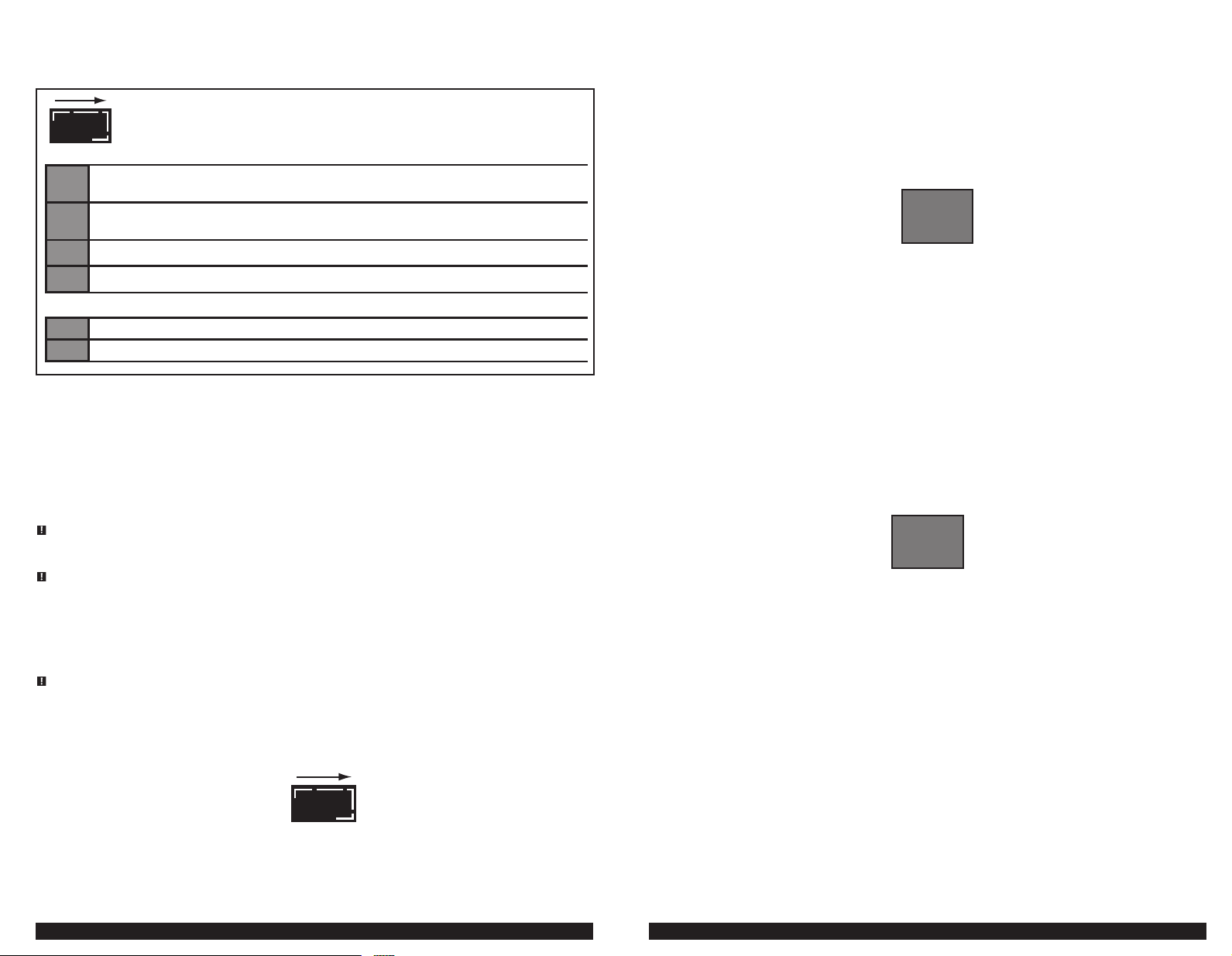
AC POWER INDICATOR: When connected to an AC outlet, digital display shows circulating pattern
to indicate the charger is properly plugged in. Disconnect charger after use.
FAULT CODES
F02
F04
F05
F06
BAD BATTERY CONNECTION: Check battery connection.
BATTERY VOLTAGE TOO LOW TO ACCEPT CHARGE: Have battery checked by certied auto service center.
OVERTIME CONDITION: Battery will not accept a charge after 18 hours of continuous charging.
Battery may have internal damage. Have battery checked by certied auto center.
OVERHEATED CONDITION: Disconnect charger and allow to cool for 30 minutes. Check for ample ventilation.
REVERSE POLARITY
OPERATION CODES
000
FUL
CHARGER STANDBY
BATTERY FULLY CHARGED
CONTROL PANEL LED INDICATORS
Battery Voltage Indicator: The appropriate LED lights when the battery voltage is automatically detected.
Show Voltage Indicator lights when battery voltage is displayed.
Float Charge Indicator lights when automatic charge monitoring is active. This feature monitors the battery voltage as it
naturally discharges and returns to maintenance charge to keep the battery charged over long periods of non-use. If there is any
loss of power to the charger during this process, the charger will automatically return to the default settings once power is restored.
The default battery selector type would be “GEL”.
OPERATING INSTRUCTIONS
DANGER: To avoid the risk of explosion and serious injury, NEVER connect this battery charger to a bank of
batteries with cells or batteries of different voltages. ALL batteries within a bank of batteries to be charged must be
the same voltage.
WARNING: TO REDUCE THE RISK OF INJURY OR PROPERTY DAMAGE:
• Always disconnect the AC plug from the AC outlet first before disconnecting the charger from the battery to be charged.
• Frame ground – Do not allow tools or other metal objects to contact frame when connecting battery cables or other
electrical wiring. Do not allow a POSITIVE wire to touch the vehicle frame, engine, or any other metal component.
• NEVER use the battery clamps for charging 36V or 48V batteries. Use the O-Ring for 36 and 48 volt applications.
• Ensure that all installation, operating instructions and safety precautions are understood and always carefully
followed by the steps outlined in the “IMPORTANT SAFETY INSTRUCTIONS” section at the front of this manual.
WARNING: A SPARK NEAR THE BATTERY MAY CAUSE AN EXPLOSION. To reduce the risk of a spark near the battery,
position AC and DC cords away from hood, door, or moving engine parts.
Charging the Battery with O-Ring or Battery Clamps
Charging general VehiCles and Boats
1. Insert either the O-Ring or battery clamps into the unit’s charger connector, then plug the unit’s 120 volt power plug into a
functioning AC outlet. The digital display will show the following red circulating pattern that loops clockwise to indicate the
charger is properly plugged in:
Connect the O-Ring or battery clamps as described in the following steps.
2. Check polarity of battery posts. POSITIVE (POS, P, +) battery post usually has larger diameter than NEGATIVE (NEG, N, –) post.
3. Determine which post of battery is grounded (connected) to the chassis. If negative post is grounded to chassis (as in most
vehicles), see 4. If positive post is grounded to the chassis, see 5.
4. For negative-grounded vehicle, connect POSITIVE (RED) clamp or O-Ring from battery charger to POSITIVE (POS, P, +)
ungrounded post of battery. Connect NEGATIVE (BLACK) clamp or O-Ring to vehicle chassis or engine block away from battery.
Do not connect clip to carburetor, fuel lines, or sheet-metal body parts. Connect to heavy gauge metal part of the frame or
engine block.
5. For positive-grounded vehicle, connect NEGATIVE (BLACK) clamp O-Ring from battery charger to NEGATIVE (NEG, N, –)
ungrounded post of battery. Connect POSITIVE (RED) clamp or O-Ring to vehicle chassis or engine block away from battery.
Do not connect clip to carburetor, fuel lines or sheet-metal body parts. Connect to a heavy gauge metal part of the frame or
engine block.
6. When the charger is properly connected to the battery, the unit will automatically detect the battery voltage (6V, 12V, 24V, 32V
or 48V) and the appropriate battery voltage indicator LED will light. The 3-character digital display will show “000” to indicate
the charger is in standby mode (described at the end of this section) and is ready to use.
Note
: The unit may take several seconds to detect the battery voltage and during this period, pressing any buttons will have no effect.
7. Press the battery type selector button until the desired battery type LED lights. A beep will sound for each press of the button.
8. Press the rapid charge button or maintenance charge button to start the charging process. A beep will sound. The digital
Once the unit is in rapid charge mode, maintenance charging mode can be alternatively selected by pressing the maintenance
9. When the charging is complete, the 3-character digital display will display “FUL”.
“000” displays before proceeding to the next step.
The default selection is “GEL” type battery. Selecting an incorrect battery type may adversely affect charging performance. Refer to the battery
Notes:
manufacturer’s specifications for battery type.
Make this selection BEFORE proceeding to the next step, as battery type cannot be selected once
charging has begun.
display will flash few times and will show the output current that is charging the battery.
If the digital display shows “F02”, the connection to the battery terminals is bad. Follow the steps outlined in “Important Safety Instructions” at the
Notes:
front of this manual to disconnect, clean battery terminals, then reconnect.
If the digital display shows “F06”, the RED (POSITIVE) and BLACK (NEGATIVE) clamps or O-rings are incorrectly connected to battery terminals. The
unit will sound a continuous alarm until the clamps or O-rings are disconnected. Follow the steps outlined in “Important Safety Instructions” at the
front of this manual to disconnect, then reconnect in correct polarity.
The unit will automatically adjust the output current.
If the battery is already charged to nearly full capacity, the unit’s output current may be reduced by a few amperes, despite the unit rating.
charge button. Refer to the section of “Battery Maintenance Charging” section for further information.
000
Wait until the
FUL
Once “FUL” is displayed the charger may switch to another voltage, for instance from 6 to 12 volts or 36 to 48 volts, and charge
at 2 amps for a short period, then return to the correct battery voltage and display “FUL” again. This is normal, as the unit’s
microprocessor ensures the battery voltage detection was accurate.
IMPORTANT: Once the battery is fully charged, the unit will NOT automatically shut off. The unit will continue monitoring
the battery voltage. When the battery voltage drops below a predetermined value, the charger will automatically go into float
charging mode and the float charge indicator will light. This feature is ideal for maintaining a fully charged battery over long
periods non-use.
If there is any loss of power to the unit during the charging process, the unit will automatically return to the default settings when power is restored.
Note:
The battery type would be “GEL.” You must stop the charging process and use the battery type selector button to re-select the battery type if you are
10. To end the charging function: If you pressed the rapid charge button to initiate the charging process, then press the rapid
11. To turn the unit OFF, follow the steps for disconnecting the unit outlined in “Important Safety Instructions” at the front of this
charging a wet or AGM battery.
charge button again to stop charging. Alternately, if you pressed the maintenance charge button to initiate the charging
process, then press the maintenance button again to stop charging. A beep will sound. The 3-character digital display will
show “000” to indicate the charger is back in standby mode.
manual to disconnect.
8 9
Page 6

Charging golf Carts
WARNING: TO REDUCE THE RISK OF INJURY OR PROPERTY DAMAGE: Make sure the golf cart power is turned OFF
before attempting charging procedures. Refer to the golf cart user manual.
1. Insert either the O-Ring or battery clamps into the unit’s charger connector, then plug the unit’s 120 volt power plug into a
functioning AC outlet. The digital display will show the following red circulating pattern that loops clockwise to indicate the
charger is properly plugged in:
Connect the O-Ring or battery clamps as described in the following steps (refer to the following examples of golf cart battery
configurations to locate switches and terminals).
2. Place the TOW/RUN switch in the TOW position before connecting to the battery post.
3. Connect POSITIVE (RED) clamp or O-Ring from battery charger to POSITIVE (POS, P, +) terminal of battery that is connected to
the solenoid.
4. Connect NEGATIVE (BLACK) clamp or O-Ring from battery charger to NEGATIVE (NEG, N, -) terminal of battery that is connected
to the solenoid.
Style A Electric Battery Configuration
CONNEC T THE NEGATIVE
BLACK CLAMP OR
ORING TO HERE
CONNEC T THE POSITIVE
RED CLAMP OR ORING
TO HERE
Style B Electric Battery Configuration
TOW/RUN
SWITCH
CONNEC T THE NEGATIVE
BLACK CLAMP OR
ORING TO HERE
TOW/RUN
SWITCH
CONNEC T THE POSITIVE
RED CLAMP OR ORING
TO HERE
Style C Electric Battery Configuration
CONNEC T THE POSITIVE
RED CLAMP OR ORING
TO HERE
TOW/RUN
SWITCH
5. When the charger is properly connected to the battery, the unit will automatically detect the battery voltage (6V, 12V, 24V, 32V
or 48V) and the appropriate battery voltage indicator LED will light. The 3-character digital display will show “000” to indicate
the charger is in standby mode (described at the end of this section) and is ready to use.
Note
: The unit may take several seconds to detect the battery voltage and during this period, pressing any buttons will have no effect.
6. Press the battery type selector button until the desired battery type LED lights. A beep will sound for each press of the button.
“000” displays before proceeding to the next step.
The default selection is “GEL” type battery. Selecting an incorrect battery type may adversely affect charging performance. Refer to the battery
Notes:
manufacturer’s specifications for battery type.
Make this selection BEFORE proceeding to the next step, as battery type cannot be selected once
charging has begun.
000
CONNEC T THE NEGATIVE
BLACK CLAMP OR
ORING TO HERE
Wait until the
10 11
Page 7

7. Press the rapid charge button or maintenance charge button to start the charging process. A beep will sound. The digital
display will flash few times and will show the output current that is charging the battery.
If the digital display shows “F02”, the connection to the battery terminals is bad. Follow the steps outlined in “Important Safety Instructions” at the
Notes:
front of this manual to disconnect, clean battery terminals, then reconnect.
If the digital display shows “F06”, the RED (POSITIVE) and BLACK (NEGATIVE) clamps or O-rings are incorrectly connected to battery terminals. The
unit will sound a continuous alarm until the clamps or O-rings are disconnected. Follow the steps outlined in “Important Safety Instructions” at the
front of this manual to disconnect, then reconnect in correct polarity.
The unit will automatically adjust the output current.
If the battery is already charged to nearly full capacity, the unit’s output current may be reduced by a few amperes, despite the unit rating.
Once the unit is in rapid charge mode, maintenance charging mode can be alternatively selected by pressing the maintenance
charge button. Refer to the section of “Battery Maintenance Charging” section for further information.
8. When the charging is complete, the 3-character digital display will display “FUL”.
FUL
Once “FUL” is displayed the charger may switch to another voltage, for instance from 6 to 12 volts or 36 to 48 volts, and charge
at 2 amps for a short period, then return to the correct battery voltage and display “FUL” again. This is normal, as the unit’s
microprocessor ensures the battery voltage detection was accurate.
IMPORTANT: Once the battery is fully charged, the unit will NOT automatically shut off. The unit will continue monitoring
the battery voltage. When the battery voltage drops below a predetermined value, the charger will automatically go into float
charging mode and the float charge indicator will light. This feature is ideal for maintaining a fully charged battery over long
periods non-use.
If there is any loss of power to the unit during the charging process, the unit will automatically return to the default settings when power is restored.
Note:
The battery type would be “GEL.” You must stop the charging process and use the battery type selector button to re-select the battery type if you are
9. To end the charging function: If you pressed the rapid charge button to initiate the charging process, then press the rapid
10. To turn the unit OFF, follow the steps for disconnecting the unit outlined in “Important Safety Instructions” at the front of this
Charging the Battery with the Round Cart Connector or Rectangular Cart Connector
charging. Attempting to charge when connectors are not fully engaged may cause property damage or injury.
IMPORTANT: The O-Ring connectors are universal to all golf carts. Some carts that use the Round and Rectangular Simple
connectors have an on-board computer that can inhibit charging. The O-Ring connectors are recommended in this instance. Refer to
the vehicle owner’s manual.
1. Insert either the Round Cart Connector or Rectangular Cart Connector into the unit’s charger connector.
2. Then plug the unit’s 120 volts power plug into a functioning AC outlet. The digital display will show the following red
3. Connect the other end of either the Round Cart Connector or Rectangular Cart Connector into the golf cart’s charging port.
4. When the charger is properly connected to the battery, the unit will automatically detect the battery voltage (6V, 12V, 24V, 32V
5. Press the battery type selector button until the desired battery type LED lights. A beep will sound for each press of the button.
charging a wet or AGM battery.
charge button again to stop charging. Alternately, if you pressed the maintenance charge button to initiate the charging
process, then press the maintenance button again to stop charging. A beep will sound. The 3-character digital display will
show “000” to indicate the charger is back in standby mode.
manual to disconnect.
WARNING: Make sure the round connector or rectangular connector are fully engaged (securely connected) before
circulating pattern that loops clockwise to indicate the charger is properly plugged in:
Make sure there is good contact.
or 48V) and the appropriate battery voltage indicator LED will light. The 3-character digital display will show “000” to indicate
the charger is in standby mode (described at the end of this section) and is ready to use.
000
Note
: The unit may take several seconds to detect the battery voltage and during this period, pressing any buttons will have no effect.
“000” displays before proceeding to the next step.
The default selection is “GEL” type battery. Selecting an incorrect battery type may adversely affect charging performance. Refer to the battery
Notes:
manufacturer’s specifications for battery type.
Wait until the
Make this selection BEFORE proceeding to the next step, as battery type cannot be selected once
6. Press the rapid charge button or maintenance charge button to start the charging process. A beep will sound. The digital
Once the unit is in rapid charge mode, maintenance charging mode can be alternatively selected by pressing the maintenance
7. When the charging is complete, the 3-character digital display will display “FUL”.
charging has begun.
display will flash few times and will show the output current that is charging the battery.
If the digital display shows “F02”, the connection to the battery terminals is bad. Follow the steps outlined in “Important Safety Instructions” at the
Notes:
front of this manual to disconnect, clean battery terminals, then reconnect.
If the digital display shows “F06”, the RED (POSITIVE) and BLACK (NEGATIVE) clamps or O-rings are incorrectly connected to battery terminals. The
unit will sound a continuous alarm until the clamps or O-rings are disconnected. Follow the steps outlined in “Important Safety Instructions” at the
front of this manual to disconnect, then reconnect in correct polarity.
The unit will automatically adjust the output current.
If the battery is already charged to nearly full capacity, the unit’s output current may be reduced by a few amperes, despite the unit rating.
charge button. Refer to the section of “Battery Maintenance Charging” section for further information.
FUL
Once “FUL” is displayed the charger may switch to another voltage, for instance from 6 to 12 volts or 36 to 48 volts, and charge
at 2 amps for a short period, then return to the correct battery voltage and display “FUL” again. This is normal, as the unit’s
microprocessor ensures the battery voltage detection was accurate.
IMPORTANT: Once the battery is fully charged, the unit will NOT automatically shut off. The unit will continue monitoring
the battery voltage. When the battery voltage drops below a predetermined value, the charger will automatically go into float
charging mode and the float charge indicator will light. This feature is ideal for maintaining a fully charged battery over long
periods non-use.
If there is any loss of power to the unit during the charging process, the unit will automatically return to the default settings when power is restored.
Note:
The battery type would be “GEL.” You must stop the charging process and use the battery type selector button to re-select the battery type if you are
8. To end the charging function: If you pressed the rapid charge button to initiate the charging process, then press the rapid
9. To turn the unit OFF, follow the steps for disconnecting the unit outlined in “Important Safety Instructions” at the front of this
IMPORTANT: When disconnecting charger, first disconnect AC cord, then unplug the Round Cart Connector or Rectangular Cart
Connector from the golf cart’s charging port.
Checking the Battery Voltage
1. Set up the battery charger and connect to the battery following steps 1 through 5 in either the “Charging the Battery with
When the unit is in standby mode:
2. Press the battery voltage button. A beep will sound and the show battery voltage LED will light. The digital display shows the
3. Press the battery voltage button again to end the process. A beep will sound and the show battery voltage LED will turn off.
When the unit is in maintenance charging or rapid charging mode:
2. Press the battery voltage button. A beep will sound and the show battery voltage LED will light. The digital display shows the
3. Press the battery voltage button again to end the process. A beep will sound and the show battery voltage LED will turn off.
4. To turn the unit OFF, follow the steps for disconnecting the unit outlined in “Important Safety Instructions” at the front of this
Battery Maintenance Charging
1. Set up the battery charger and connect to the battery following steps 1 through 5 in either the “Charging the Battery with
2. Press the maintenance charge button. A beep will sound. The 3-character digital display will flash few times and then show
3. To end the charging function, press the maintenance charge button again. A beep will sound. The 3-character digital display
4. To turn the unit OFF, follow the steps for disconnecting the unit outlined in “Important Safety Instructions” at the front of this
charging a wet or AGM battery.
charge button again to stop charging. Alternately, if you pressed the maintenance charge button to initiate the charging
process, then press the maintenance button again to stop charging. A beep will sound. The 3-character digital display will
show “000” to indicate the charger is back in standby mode.
manual to disconnect.
O-ring or Battery Clamps” or the “Charging the Battery with the Round Cart Connector or Rectangular Cart Connector“ section.
current voltage of the connected battery.
The digital display will show “000”.
current voltage of the connected battery.
The digital display will show the output current.
manual to disconnect.
O-ring or Battery Clamps” or the “Charging the Battery with the Round Cart Connector or Rectangular Cart Connector“ section.
the output current that is charging the battery. In this mode, the output current is 2 amps.
will show “000” to indicate the charger is back in standby mode.
manual to disconnect.
12 13
Page 8

TROUBLESHOOTING
Unit Not Charging
• Check that the charger is properly connected to a live 120 volt AC outlet.
• Make sure all connections are secure.
• Observe the 3-character digital display for fault codes. Refer to the chart on page 6 (and on the bottom of the unit) for an
explanation and/or remedy. Also refer to the Notes under step 8 in the “Charging the Battery with O-ring or Battery Clamps”
section.
• If the battery to be charged has fallen below 2 volts, the battery cannot be recharged with this charger.
CARE AND MAINTENANCE
Storage
• Store the unit in a clean, dry, cool place when not in use.
• Clean the unit casing and cords (as necessary) with a dry (or slightly damp) cloth. Ensure that unit is completely disconnected
from battery and power source before cleaning.
• To maintain the operating condition and maximize the life of the charger cords, always coil them loosely for storage. Do not crimp
them with a tight band.
ACCESSORIES
Recommended accessories for use with your tool are available from your local dealer. If you need assistance regarding accessories,
please contact manufacturer at (877) 571-2391.
WARNING: The use of any accessory not recommended for use with this appliance could be hazardous.
SERVICE INFORMATION
Whether you need technical advice, repair, or genuine factory replacement parts, contact the manufacturer at (877) 571-2391.
ONEYEAR LIMITED WARRANTY
The manufacturer warrants this product against defects in materials and workmanship for a period of ONE (1) YEAR from the date
of retail purchase by the original end-user purchaser (“Warranty Period”).
If there is a defect and a valid claim is received within the Warranty Period, the defective product can be replaced or repaired in
the following ways: (1) Return the product to the retailer where product was purchased for an exchange (provided that the store
is a participating retailer). Returns to retailer should be made within the time period of the retailer’s return policy for exchanges
only (usually 30 to 90 days after the sale). Proof of purchase may be required. Please check with the retailer for their specific return
policy regarding returns that are beyond the time set for exchanges. (2) Return the product to the manufacturer for repair or
replacement at manufacturer’s option. Proof of purchase may be required by manufacturer.
This warranty does not apply to accessories, bulbs, fuses and batteries; defects resulting from normal wear and tear, accidents;
damages sustained during shipping; alterations; unauthorized use or repair; neglect, misuse, abuse; and failure to follow
instructions for care and maintenance for the product.
This warranty gives you, the original retail purchaser, specific legal rights and you may have other rights which vary from state to
state or province to province. This product is not intended for commercial use.
Please complete the Product Registration Card and return within 30 days from purchase of the product to: Baccus Global LLC, 595 S.
Federal Highway, Suite 210, Boca Raton, FL 33432. Baccus Global LLC, toll-free number: (877) 571-2391.
SPECIFICATIONS
Input: 120 Vac, 60 Hz, 650W
Output: 6 Vdc/12Vdc/24Vdc, 20A
36Vdc, 12A
48Vdc, 10A
Imported by
Baccus Global LLC
595 S. Federal Highway, Suite 210
Boca Raton, FL 33432
(877) 571-2391
RD011411
CARACTERÍSTICAS
INDIC ADOR DIGITAL DE 3 C ARACTERES
INDIC ADOR
PARA DEMOSTRAR
VOLTAJE
INDIC ADOR
DE CARGA DEL
FLOTADOR
BOTÓN DEL
VOLTAJE DE LA
BATERÍA
BOTÓN DEL
SELEC TOR
DEL CARGA DEL
MANTENIMIENTO
DE LA BATERÍA
INDIC ADOR DEL
VOLTAJE DE LA
BATERÍA
INDIC ADOR DE
TIPO DE LA
BATERÍA
BOTÓN PARA
SELECCIONAR
EL TIPO DE LA
BATERÍA
BOTÓN DE LA
CARGA RÁPIDO
14 15
Page 9

COMPARTIMENTO DE ALMACENAJE
PARA PINZAS DE BATERÍA
CONEC TOR DE
CARGADOR SE UNE A
ANILLOS “O”, PINZAS DE
BATERÍA, CONEC TADOR
REDONDO DEL C ARRO
O CONECTADOR
RECTANGULAR DEL
CARRO
COMPARTIMIENTO
DEL ALMACENAJE DE
LA CUERDA DE LA C A
ENCHUFE DE LA CA
DE 120 VOLTIOS
Este dispositivo cumple con la parte 15 de las normas de la Comisión Federal de Comunicaciones de Estados Unidos (FCC). La
operación está sujeta a las dos condiciones siguientes: (1) este dispositivo no puede causar interferencia perjudicial y (2) este
mecanismo debe aceptar cualquier interferencia recibida, incluida la in-terferencia que puede provocar una operación
no deseada.
Este equipo ha sido probado y se encontró que cumple con los límites para dispositivo digital Clase B, según la parte 15 de
las normas de la FCC. Estos límites están diseñados para brindar protección razonable contra interferencia perjudicial en una
instalación residencial. Este equipo genera, usa y puede irradiar energía en frecuencia de radio y, si no se instala y se usa de
acuerdo con las instrucciones, puede provocar interferencia perjudicial en las comunicaciones de radio. Sin embargo, no hay
garantía de que la interferencia no ocurra en una instalación en particular. Si el equipo provoca interferencia perjudicial en la
recepción de radio o televisión, lo que se puede determinar al apagar y encender el equipo, el usuario debe tratar de corregir
la interferencia mediante una o más de las siguientes medidas:
• Cambiar la orientación o la ubicación de la antena de recepción.
• Aumentar la separación entre el equipo y el receptor.
• Conectar el equipo a un tomacorriente sobre un circuito diferente de aquel al que está conectado el receptor.
• Consultar al vendedor o pedir la ayuda de un técnico en radio y televisión con experiencia.
Los cambios o las modificaciones no aprobados por el partido responsable de conformidad podían anular la autoridad del
usuario para funcionar el equipo.
ADVERTENCIAS E INSTRUCCIONES DE SEGURIDAD GENERALES
LEA LAS INSTRUCCIONES
ADVERTENCIA: Lea todas las instrucciones antes de operar el cargador de batería. El incumplimiento de todas las
instrucciones enumeradas a continuación puede provocar una descarga eléctrica, un incendio o lesiones graves.
NORMAS DE SEGURIDAD / DEFINICIONES
PELIGRO: Indica una situación de peligro inminente que, si no se evita, provocará la muerte o lesiones graves.
ADVERTENCIA: Indica una situación de peligro inminente que, si no se evita, provocará la muerte o lesiones graves.
PRECAUCIÓN: Indica una situación de peligro potencial que, si no se evita, puede provocar lesiones leves o moderadas.
PRECAUCIÓN: Utilizado sin el símbolo de alerta de seguridad indica una situación de peligro potencial que, si no se evita, puede
provocar daños en la propiedad.
RIESGO DE OPERACIÓN INSEGURA. Cuando se utilizan herramientas o equipos, siempre se deben respetar las precauciones
de seguridad para reducir el riesgo de lesiones personales. La operación, el mantenimiento o la modificación incorrectos de
herramientas o equipos pueden provocar lesiones graves y daños a la propiedad. Las herramientas y los equipos están diseñados
para determinados usos. Fabricante recomienda encarecidamente que NO se modifique este producto y que NO se utilice para
ningún otro uso que aquél para el que fue diseñado. Lea y comprenda todas las instrucciones operativas y las advertencias antes de
utilizar cualquier herramienta o equipo.
ANILLO “O” PINZAS DE LA
BATERÍA
PARA EL USO CON LAS
BATERÍAS 6V, 12V, O
24V SOL AMENTE
INSTRUCCIONES IMPORTANTES SOBRE SEGURIDAD
• Esta unidad fue diseñada para el uso del hogar solamente.
• Evite las condiciones ambientales peligrosas. No utilice artefactos en zonas húmedas o mojadas. No utilice artefactos bajo la
lluvia.
• Mantenga a los niños ausentes. Guarde lejos de niños. ¡Esto no es un juguete!
• Almacén dentro. Cuando son parados, los cargadores de batería deben ser almacenados dentro en los lugares secos, y altos o
inmovilizados – fuera del alcance de niños.
• Desenchufe el cargador de batería cuando no se está utilizando.
• Compruebe la unidad periódicamente para el desgaste. Tome a un técnico calificado para el reemplazo de partes llevadas
puestas o defectuosas inmediatamente.
• Leído y entienden este manual de instrucción antes de usar esta unidad.
• PRIMEROS AUXILIOS – PIEL: Si el ácido de la batería entra en contacto con la piel, enjuáguese inmediatamente con agua, luego
CONEC TADOR
REDONDO DEL
CARRO
16 17
CONEC TADOR
RECTANGULAR
DEL CARRO
lávese con agua y jabón. Si se presenta enrojecimiento, dolor o irritación, busque asistencia médica de inmediato.
OJOS: Si el ácido de la batería entra en contacto con los ojos, lávese los ojos inmediatamente durante 15 minutos como mínimo y
busque asistencia médica de inmediato.
INSTRUCCIONES DE SEGURIDAD ESPECÍFICAS PARA LOS CABLES ELÉCTRICOS
• No tire del cable. Nunca transporte el aparato por el cable ni lo jale para desconectarlo del tomacorriente. Mantenga el cable
alejado del calor, el aceite y los bordes afilados. Tire de la cuerda por el enchufe algo que cord al desenchufar la unidad.
• La protección del interruptor de corte por falla a tierra (GFCI) debe aplicarse a los circuitos o los tomacorrientes que se
utilizarán. Hay tomacorrientes con protección GFCI incorporada que pueden utilizarse para tomar esta medida de seguridad.
Page 10

Cables prolongadores
ADVERTENCIA: Una cuerda de extensión no debe ser utilizada a menos que absolutamente sea necesario. El uso de la cuerda de
extensión incorrecta podía dar lugar a un riesgo de fuego y descarga eléctrica. Si se utiliza una cuerda de extensión, cerciórese de
que los pernos de la cuerda de extensión sean el mismo número, tamaño y forma que ésos en el cargador.
Asegúrese de que el cable prolongador esté en buenas condiciones. Cuando utilice un cable prolongador, asegúrese de que tenga la
capacidad para conducir la corriente que su producto exige. Un cable de menor capacidad provocará una disminución en el voltaje
de la línea, lo cual producirá una pérdida de potencia y sobrecalentamiento. La siguiente tabla muestra la medida correcta que
debe utilizar según la longitud del cable y la capacidad nominal en amperios indicada en la placa. En caso de duda, utilice el calibre
inmediatamente superior. Cuanto menor es el número de calibre, más grueso es el cable.
Tamaño mínimo recomendado del AWG para las cuerdas de extensión para los cargadores de batería
Grado de la entrada de la CA Tamaño de las normas americanas de cableado (AWG) de la cuerd
Amperios
Igual a o
mayor que que
0 2 18 18 18 16
2 3 18 18 16 14
3 4 18 18 16 14
4 5 18 18 14 12
5 6 18 16 14 12
6 8 18 16 12 10
8 10 18 14 12 10
10 12 16 14 10 8
12 14 16 12 10 8
14 16 16 12 10 8
16 18 14 12 8 8
Seguridad del cable eléctrico
Este cargador de batería es para el uso en un nominal circuito de 120 voltios, y tiene un enchufe que pone a tierra que parezca
el enchufe ilustrado en el bosquejo A en la ilustración abajo. Un adaptador temporal, que parece al adaptador ilustrado en
esbozos B y C, puede ser usado para unir este enchufe a un receptáculo de dos postes como mostrado en el esbozo B si una salida
correctamente basada no está disponible. El adaptador temporal debería ser usado sólo hasta que una salida correctamente basada
puede ser instalada por un electricista calificado.
rígido verde coloreado o arrastra la ampliación del adaptador debe estar relacionado con una salida correctamente basada – hacen
seguro es basado. Si es necesario, sustituya el tornillo de plato de tapa de salida original por un tornillo más largo que asegurará el
oído de adaptador o arrastrará a la tapa de salida platean y hacen la unión de tierra a la salida basada.
18 20 14 12 8 6
PELIGRO: Antes de usar el adaptador como ilustrado, estar seguro lo que centra el tornillo del plato de salida es basado. El oído
Pero menos
25 (7.6) 50 (15.2) 100 (30.5) 150 (45.6)
Longitud de la cuerda, pies (m)
INSTRUCCIONES DE SEGURIDAD ESPECÍFICAS PARA LOS CARGADORES DE BATERÍA
PELIGRO: Para evitar el riesgo de explosión y de lesión seria, NUNCA conecte este cargador de batería con un
banco de baterías con las células o de baterías de diversos voltajes. TODAS las baterías dentro de un banco de las
baterías que se cargarán deben ser el mismo voltaje.
ADVERTENCIA, PELIGRO DE ESTALLIDO: No utilice la unidad para cargar las baterías secas que se usan normalmente con los
aparatos domésticos Estas baterías pueden estallar y provocar lesiones a las personas y daños a la propiedad. No está diseñada para
proveer energía a un sistema eléctrico de bajo voltaje que no sea para arrancar un motor.
ADVERTENCIA: PARA REDUCIR EL RIESGO DE DESCARGA ELÉCTRICA:
• No exponga el cargador o sus componentes al agua o a ningún otro líquido; o utilice el cargador en la lluvia o la nieve.
• Nunca sumerja la unidad en el agua ni en ningún otro líquido, ni la utilice cuando esté húmeda.
ADVERTENCIA: RIESGO DE GASES EXPLOSIVOS:
• Trabajar cerca de una batería de plomo ácido es peligroso. Las baterías generan gases explosivos durante su funcionamiento
normal. Por esta razón, es muy importante que lea este manual siempre antes de utilizar la batería de urgencia y que siga las
instrucciones con exactitud.
• Para reducir el riesgo de explosión de la batería, siga estas instrucciones y las publicadas por el fabricante de la batería y el fabricante
de cualquier equipo que tenga la intención de utilizar este cargador de batería. Revise las indicaciones sobre precauciones en estos
productos y en el motor.
• Este equipo emplea piezas (interruptores y relés) que producen arcos o chispas. Por lo tanto, si utiliza la unidad en una cochera o
un área cerrada, DEBE colocarla a no menos de 46 cm (18 pulgadas) por encima del piso.
• PARA REDUCIR EL RIESGO DE LESIONES, ESTA UNIDAD SÓLO DEBE SER OPERADA POR ADULTOS, NO FUE DISEÑADA PARA QUE LA
UTILICEN LOS NIÑOS.
ADVERTENCIA: PARA REDUCIR EL RIESGO DE INCENDIO:
• No opere cerca de materiales, vapores o gases inflamables.
• No lo exponga al calor extremo o a las llamas.
Ninguno de estos acciones pueden causar daño eléctrico serio y/o un fuego.
PRECAUCIÓN: PARA REDUCIR EL RIESGO DE DAÑO A LA PROPIEDAD: Nunca utilice las abrazaderas de la batería para
cargar las baterías 36V o 48V. Las abrazaderas de la batería están para el uso en las baterías 6V, 12V y 24V; y las
baterías 8V en una batería agrupan el balance 24V* solamente. Utilice el anillo “O” o los conectadores rápidos para las
baterías o los grupos de la batería de 36 y 48 voltios. *No para el uso en las baterías individuales 8V.
• El enfriamiento correcto es fundamental al operar el cargador de batería. No coloque la unidad cerca de los orificios de
ventilación del vehículo ni la exponga a la luz solar directa.
• Uso de suplementos y accesorios. El uso de accesorios o dispositivos no recomendados para este aparato puede resultar
peligroso.
• Manténgase alerta. Use el sentido común. No haga funcionar el cargador de batería cuando está cansado.
• Verifique que no haya piezas dañadas. Cualquier parte se dañe que se debe reparar o substituir correctamente por un centro
de servicio autorizado a menos que se indicare contrariamente a otra parte en este manual de la instrucción antes de que sea
futuro utiliza.
• No funcione el cargador de batería cerca de líquidos inflamables o en atmósferas gaseosas o explosivas. Los interruptores y
los relais pueden chispear, y las chispas pudieron encender humos.
PRECAUCIÓN: PARA REDUCIR EL RIESGO DE LESIONES O DAÑO A LA PROPIEDAD:
• NUNCA INTENTE ARRANCAR MEDIANTE PUENTE UNA BATERÍA CONGELADA.
• Los vehículos que tienen sistemas automatizados a bordo pueden ser dañados si se carga la batería del vehículo.
Antes de cargar, lea el manual del dueño de vehículo.
• No cargue la batería mientras que el motor está funcionando; o tentativa de funcionar el vehículo mientras que la batería está
cargando.
• Manténgase alejado de las paletas de ventilador, correas, poleas y otras partes que pueden provocar lesiones a las personas.
• Cuando trabaje con baterías de plomo-ácido, asegúrese de que siempre haya ayuda inmediata disponible en caso de accidente o
emergencia.
• Utilice siempre protección para los ojos al emplear este producto; el contacto con el ácido de la batería puede producir ceguera o
quemaduras graves. Conozca los procedimientos de primeros auxilios para el caso de contacto accidental con el ácido de la batería.
• Mantenga cerca suficiente agua fresca y jabón en caso que el ácido de la batería entre en contacto con la piel.
• Si el ácido de la batería entra en contacto con la piel o la ropa, enjuáguese inmediatamente con agua y jabón durante por lo
menos 10 minutos. Busque asistencia médica de inmediato.
• Nunca fume o permita una chispa o flamee en la vecindad de la batería del vehículo, del motor o del cargador de batería.
• Quítese todos los artículos personales que sean de metal, como anillos, pulseras y relojes cuando trabaje con una batería de ácido
de plomo. Una batería de plomo puede producir un cortocircuito actual arriba bastante para soldar con autógena un anillo, o el
objeto similar del metal, para pelar causar una quemadura severa.
• Nunca permita que el ácido de la batería entre en contacto con esta unidad.
• No opere esta unidad en un área cerrada ni restrinja la ventilación de alguna forma.
• Apague siempre el cargador de batería desenchufándolo al no ser utilizado.
• NO ABRA EL CARGADOR DE BATERÍA: no hay piezas que el usuario pueda reparar en su interior. Apertura del convertidor anulará
la garantía del fabricante.
• Opere la unidad solamente como se describe en este manual de instrucciones.
18 19
Page 11

• Compruebe el cargador y los componentes de batería periódicamente para saber si hay desgaste y rasgón. Vuelva al fabricante
para el reemplazo de piezas gastadas o defectuosas inmediatamente.
PREPARACIÓN PARA LA CARGA
1. Asegure que el área alrededor él la batería es bien ventilada mientras la batería es el precio.
2. Si es necesario retirar la batería del vehículo para cargarla, o para limpiar los terminales, retire siempre primero de la batería el
terminal puesto a tierra. Asegúrese de que todos los accesorios del vehículo estén apagados, para no causar un arco eléctrico.
3. Limpie los terminales de la batería, tomando cuidado para evitar conseguir el material corrosivo en ojos.
4. Agregue agua destilada en cada celda hasta que el ácido de la batería alcance el nivel especificado en el manual del fabricante.
Esto ayuda a purgar el exceso de gas de las celdas. No llene de más. Para una batería sin tapas de celda (que no requiere
mantenimiento), siga cuidadosamente las instrucciones de carga del fabricante.
5. Estudie todas las precauciones específicas del fabricante de la batería, tales como si retirar o no las tapas de las celdas mientras
se carga, y la velocidad de carga recomendada.
Localización del cargador
• Ubique el cargador tan lejos de la batería como lo permitan los cables.
• Nunca ubique el cargador directamente sobre la batería que se está cargando; los gases de la batería producirán corrosión y daños
al cargador.
• Nunca permita que el ácido de la batería gotee sobre el cargador cuando lee la gravedad o llena la batería.
• Nunca opere el cargador en un área cerrada ni restrinja la ventilación de manera alguna.
• Las baterías marinas se pueden retirar y cargar en tierra.
• No coloque una batería sobre el cargador.
Precauciones para la conexión de las pinzas del cargador
1. Conecte y desconecte las abrazaderas del anillo “O” o de la salida solamente después de quitar la cuerda de la CA del enchufe
eléctrico.
2. Nunca permita el anillo “O” o hacer salir las abrazaderas para tocarse.
3. Fije las pinzas a la batería y al bastidor como se indica en “Batería instalada en el vehículo”, pasos 5 y 6, y en “Batería fuera del
vehículo”, pasos 2, 4 y 5.
Cuando la batería está instalada en un vehículo, siga estos pasos
ADVERTENCIA: Una chispa cerca de la batería puede causar una explosión. Para reducir riesgo de una chispa cerca
de la batería:
1. Mantenga los cables de CA y CC alejados del capó, la puerta las partes moviles del motor.
2. Manténgase alejado de las paletas de ventilador, correas, poleas y otras partes que pueden provocar lesiones a las personas.
3. Controle la polaridad de los bornes de la batería. El borne POSITIVO (POS, P, +) de la batería generalmente tiene mayor
diámetro que el borne NEGATIVO (NEG, N, –).
4. Determine qué borne de la batería está puesto a tierra (conectado) al bastidor. Si el borne negativo está puesto a tierra en el
bastidor (como en la mayoría de los vehículos), vea 5. Si el borne positivo está puesto a tierra en el bastidor, vea 6.
5. Para un vehículo puesto a tierra con el negativo, conecte la pinza o el anillo “O” del POSITIVO (ROJA) del cargador de batería al
borne sin conexión a tierra POSITIVO (POS, P, +) de la batería. Conecte la pinza o el anillo “O” del NEGATIVO (NEGRA) al bastidor
del vehículo o al bloque del motor, lejos de la batería. No conecte la pinza al carburador, las cañerías de combustible o a las
partes de chapa de la carrocería. Conecte a una pieza de metal sólida del bastidor o del bloque del motor.
6. Para un vehículo puesto a tierra con el positivo, conecte la pinza o el anillo “O” del NEGATIVO (NEGRA) del cargador de batería
al borne sin conexión a tierra NEGATIVO (NEG, N, –) de la batería. Conecte la pinza o el anillo “O” del POSITIVO (ROJA) al
bastidor del vehículo o al bloque del motor, lejos de la batería. No conecte la pinza o el anillo “O” al carburador, las cañerías de
combustible o a las partes de chapa de la carrocería. Conecte a una pieza de metal sólida del bastidor o del bloque del motor.
7. Cuando desconecta el cargador, coloque todos los interruptores en apagado (Off), desconecte el cable de CA, retire la pinza del
bastidor del vehículo, y luego retire la pinza del terminal de la batería.
8. No cargue la batería mientras el motor está en marcha.
9. Vea las instrucciones de operación para obtener información sobre la duración de la carga.
Cuando la batería ha sido retirada del vehículo, siga estos pasos
ADVERTENCIA: Una chispa cerca de la batería puede causar una explosión. Para reducir riesgo de una chispa cerca
de la batería:
1. Controle la polaridad de los bornes de la batería. El borne positivo (marcado POS, P, +) generalmente tiene mayor diámetro
que el borne negativo de la batería (marcado NEG, N, –).
2. Conecte un cable de 60 cm (24 pulgadas)(longitud mínima) Nº 6 AWG aislado, para batería al borne negativo de la batería
(marcado NEG, N, –).
3. Conecte la pinza positiva (ROJA) de la batería al borne positivo de la batería (marcado POS, P, + o rojo).
4. Conecte cuidadosamente la pinza NEGATIVA (NEGRA) del cargador al extremo libre del cable de la batería conectado al terminal
negativo.
5. Párese tan lejos de la batería como sea posible, y no esté de cara a la batería hasta que haya hecho la conexión final.
6. Cuando desconecta el cargador, hágalo siempre en la secuencia inversa del procedimiento de conexión y corte la primera
conexión estando tan lejos de la batería como resulte posible.
Una batería marina (de bote) se debe retirar y cargar en tierra. Cargarla a bordo exige equipos diseñados especialmente para uso marino. Esta unidad NO
Nota:
está diseñada para tal uso.
CONSERVE ESTAS INSTRUCCIONES
ADVERTENCIA: PARA REDUCIR EL RIESGO DE LESIONES:
• Siga estas instrucciones y ésas publicadas por el fabricante de cualquier motor que usted se preponga utilizar con este cargador de
batería. Repase las marcas preventivas en el cargador y el motor de batería.
• Esta unidad no se piensa para el uso en las baterías individuales 8V; solamente en las baterías 8V en grupos de la
batería de 24V y de 48V.
INTRODUCCIÓN
Felicitaciones por adquirir su nuevo cargador de bateria para vehiculos y carros de golf. Lea el manual de instrucción y siga las
instrucciones cuidadosamente antes de utilizar su cargador de batería.
BOTONES DE FUNCIÓN
TIPO DE LA BATERÍA (BATTERY TYPE): Permite que el usuario seleccione el tipo húmeda, del gel o del AGM de batería para una
carga eficiente y segura. La mayoría de las baterías automotoras son baterías húmedas. Consulte las especificaciones del fabricante
de la batería para ver el tipo de batería.
CARGA RÁPIDA (RAPID CHARGE): Ajusta automáticamente la corriente de carga para permitir una carga rápida de la batería.
CARGA DE MANTENIMIENTO (MAINTENANCE CHARGE): Ajusta automáticamente la corriente de carga a 2A para ampliar la vida
de la batería.
VOLTAJE DE LA BATERÍA (BATTERY VOLTAGE): Permite que el usuario realice un cheque rápido del voltaje de la batería.
INDICADOR DIGITAL DE 3 CARACTERES
El indicador digital de tres caracteres grande en la porción superior del panel de control indica las varios condiciones y/o códigos de
estado.
Los códigos de estado se describen en el siguiente gráfico y en el fondo del cargador.
INCADOR DE CORRIENTE ALTERNA (CA): Cuando se conecta a un tomacorriente de CA, el visor
digital muestra un diseño de circulación para indicar el cargador está enchufada correctamente.
Desconecte el cargador después de usarlo.
CÓDIGOS DE FALLAS
F02
F04
F05
F06
CÓDIGOS OPERATIVOS
000
FUL
INDICADORES DEL PANEL DE CONTROL LED
Indicador del voltaje de la batería: El LED apropiado se enciende cuando el voltaje de la batería se detecta automáticamente.
Indicador para demostrar voltaje (Show Voltage Indicator) luces cuando se exhibe el voltaje de la batería.
Indicador de carga del flotador (Float Charge Indicator) se enciende cuando está activado el monitoreo de carga automática.
Esta característica supervisa el voltaje de la batería como naturalmente las descargas y las vueltas a los gastos de mantenimiento
para guardar la batería cargó durante largos periodos de la no utilización. Si se corta la energía al cargador, una vez que se restaura la
energía, el cargador volverá automáticamente a las posiciones predeterminadas. El tipo de batería del defecto seleccionada sería “gel”.
MALA CONEXIÓN DE LA BATERÍA: Controle la conexión de la batería.
EL VOLTAJE DE LA BATERÍA ESTÁ DEMASIADO BAJO PARA ACEPTAR CARGA: Haga la batería comprobar por el
centro auto certicado.
SE EXCEDIÓ EL TIEMPO DE CARGA: La batería no acepta carga después de 18 horas de carga continua.
La batería puede tener daño interno.
SOBRECALENTAMIENTO: Desconecte el cargador y permita que se enfrie durante 30 minutos.
Verique que haya mucha ventilación.
LA SALIDA DEL ALTERNADOR ESTÁ PUERA DE RANGO
CARGADOR EN ESPERA
BATERÍA TOTALMENTE CARGADA
Haga la batería comprobar por el centro auto certicado.
20 21
Page 12

INSTRUCCIONES DE OPERACIÓN
PELIGRO: Para evitar el riesgo de explosión y de lesión seria, NUNCA conecte este cargador de batería con un
banco de baterías con las células o de baterías de diversos voltajes. TODAS las baterías dentro de un banco de las
baterías que se cargarán deben ser el mismo voltaje.
ADVERTENCIA: PRECAUCIÓN: PARA REDUCIR EL RIESGO DE LESIONES O DAÑO A LA PROPIEDAD:
• Desconecte siempre el enchufe de la CA del enchufe de la CA primero antes de desconectar el cargador de la
batería que se cargará.
• Tierra de capítulo - no permita que las herramientas u otros objetos del metal entren en contacto con el marco cuando
la conexión de la batería cablegrafía o el otro cableado eléctrico. No permita que un alambre positivo toque el marco
del vehículo, el motor, o cualquie otro componente del metal.
• NUNCA utilice las abrazaderas de la batería para cargar las baterías 36V o 48V. Utilice el Anillo “O” para los usos de 36 y
48 voltios.
• Asegúrese de que toda la instalación, instrucciones de manejo y medidas de seguridad sean entendidas y seguidas
siempre cuidadosamente por los pasos contorneados en el “ SEGURIDAD IMPORTANTE INSTRUCTION“ sección en el
frente de este manual.
ADVERTENCIA: Una chispa cerca de la batería puede causar una explosión. Para reducir riesgo de una chispa cerca
de la batería, mantenga los cables de CA y CC alejados del capó, la puerta las partes moviles del motor.
Carga de batería del anillo “O” o de las pinzas de la batería
Carga de VehíCulos y de BarCos generales
1. Inserte los anillos “O” o las pinzas de la batería en el conectador del cargador de la unidad, después tape el enchufe de energía
de 120 voltios de la unidad en un enchufe de funcionamiento de la CA. El indicador digital demostrará a patrón de circulación
rojo siguiente que los lazos a la derecha para indicar el cargador están accionados correctamente:
Conecte los anillos “O” o las pinzas de la batería según lo descrito en los pasos siguientes.
2. Controle la polaridad de los bornes de la batería. El borne POSITIVO (POS, P, +) de la batería generalmente tiene mayor
diámetro que el borne NEGATIVO (NEG, N, –).
3. Determine qué borne de la batería está puesto a tierra (conectado) al bastidor. Si el borne negativo está puesto a tierra en el
bastidor (como en la mayoría de los vehículos), vea 4. Si el borne positivo está puesto a tierra en el bastidor, vea 5.
4. Para un vehículo puesto a tierra con el negativo, conecte la pinza o el anillo “O” del POSITIVO (ROJA) del cargador de batería al
borne sin conexión a tierra POSITIVO (POS, P, +) de la batería. Conecte la pinza o el anillo “O” del NEGATIVO (NEGRA) al bastidor
del vehículo o al bloque del motor, lejos de la batería. No conecte la pinza al carburador, las cañerías de combustible o a las
partes de chapa de la carrocería. Conecte a una pieza de metal sólida del bastidor o del bloque del motor.
5. Para un vehículo puesto a tierra cLn el positivo, conecte la pinza o el anillo “O” del NEGATIVO (NEGRA) del cargador de batería al
borne sin conexión a tierra NEGATIVO (NEG, N, –) de la batería. Conecte la pinza o el anillo “O” del POSITIVO (ROJA) al bastidor
del vehículo o al bloque del motor, lejos de la batería. No conecte la pinza al carburador, las cañerías de combustible o a las
partes de chapa de la carrocería. Conecte a una pieza de metal sólida del bastidor o del bloque del motor.
6. Cuando el cargador está conectado correctamente con la batería, la unidad detectará automáticamente el voltaje de la batería
(6V, 12V, 24V, 32V o 48V) y el indicador del LED del voltaje de la batería apropiado se encenderá. El indicador digital de 3
caracteres demostrará que “000” para indicar el cargador es en modo espera (descrito al final de esta sección) y que es listos para
utilizar.
Nota:
La unidad puede tardar varios segundos para detectar el voltaje de la batería y durante este período, apretando ningún botón no tendrá efecto.
7. Presione el botón para seleccionar el tipo de la batería hasta que el LED que indica el tipo deseado de la batería se encienda.
8. Presione el botón de la carga rápido o el botón del selector del carga del mantenimiento de la batería; para comenzar el
Espere hasta “000” presentaciones antes de proceder al paso siguiente.
Una señal sonora sonará para cada prensa del botón.
La selección del defecto es tipo batería del “GEL”. La selección de un tipo incorrecto de la batería puede afectar al contrario a funcionamiento de
Notas:
carga. Refiera a las especificaciones del fabricante de la batería para el tipo de la batería.
Haga esta selección ANTES de proceder al paso siguiente, pues el tipo de la batería no puede ser una vez
carga seleccionada ha comenzado.
proceso de carga. Una señal sonora sonará. El indicador digital destellará pocas veces y demostrará la corriente de salida que
está cargando la batería.
000
Notas:
Si el indicador digital demuestra “F02”, la conexión a los terminales de la batería es mala. Siga los pasos contorneados en “instrucciones de seguridad
importantes” en el frente de este manual a la desconexión, terminales limpios de la batería, después vuelva a conectar.
Si el indicador digital demuestra “F06”, las pinzas o los anillos “O” (NEGATIVOS) ROJOS (POSITIVO) y NEGROS están conectados incorrectamente
con los terminales de la batería. La unidad parecerá una alarma continua hasta las abrazaderas o los anillos “O” son desconectados.
Siga los pasos contorneados en “instrucciones de seguridad importantes” en el frente de este manual a la desconexión, después vuelva a conectar
en polaridad correcta.
La unidad ajustará automáticamente la corriente de salida.
Si la batería se carga ya casi a la capacidad plena, la corriente de salida de la unidad se puede reducir por algunos amperios, a pesar de el grado de la
Una vez que la unidad está en modo rápido de la carga, el modo de carga del mantenimiento de la batería puede ser
9. Cuando la carga es completa, el indicador digital de 3 caracteres exhibirá “FUL”.
unidad.
seleccionado alternativamente presionando el botón de los gastos de mantenimiento. Refiera a la sección “carga del
mantenimiento de la batería” para más información.
FUL
Una vez que “FUL” es demostrado el corcel puede cambiar a otro voltaje, por ejemplo de 6 a 12 voltios o 36 a 48 voltios, y a la
carga en 2 amperios por un período corto, entonces vuelve al voltaje correcto de la batería y la presentación “FUL” otra vez. Esto
es normal, como el microprocesador de la unidad asegura que el descubrimiento de voltaje de batería fuera exacto.
IMPORTANTE: Una vez que la batería esté completamente cargada, la unidad NO se apagará en forma automática. La unidad
continuará supervisando el voltaje de la batería. Cuando las caídas de voltaje de la batería debajo de un valor predeterminado,
el cargador entrarán automáticamente modo de carga del flotador y el indicador de carga del flotador se encenderá. Esta
característica es ideal para mantener una batería completamente cargada sobre la no utilización de los largos periodos.
Si hay alguna pérdida de energía a la unidad durante el proceso de carga, la unidad volverá automáticamente a los ajustes de defecto cuando se
Nota:
restaura la energía. El tipo de la batería sería “gel.” Usted debe parar el proceso de carga y utilizar el botón para seleccionar el tipo de la batería para
10. Para terminar la función de carga: Si usted presionó el botón rápido de la carga para iniciar el proceso de carga, después
11. Para apagar la unidad, siga los pasos para desconectar la unidad contorneada en “instrucciones de seguridad importantes” en
Carga de los Carros de golf
carro de golf esté cortada antes de intentar procedimientos de carga. Refiera al manual del usuario del carro de golf.
1. Inserte los anillos “O” o las pinzas de la batería en el conectador del cargador de la unidad, después tape el enchufe de energía
Conecte las pinzas del anillo o o de la batería según lo descrito en los pasos siguientes (refiera a los ejemplos siguientes de las
2. Ponga el interruptor de LA REMOLQUE/FUNCIONA (TOW/RUN) en la posición de la REMOLQUE (TOW) antes de conectar con el
3. Conecte la pinza o el Anillo “O” (ROJA) POSITIVA del cargador de batería con (posición, P, +) el terminal POSITIVO de la batería
4. Conecte la abrazadera o el Anillo “O” (NEGRA) NEGATIVA del cargador de batería con (NEG, N, -) el terminal NEGATIVO de la
reelegir el tipo de la batería si usted está cargando una batería húmedas o del AGM.
presione el botón rápido de la carga otra vez para parar el cargar. Alternativamente, si usted presionó el botón de los gastos
de mantenimiento para iniciar el proceso de carga, después presione el botón del mantenimiento otra vez para parar el cargar.
Una señal sonora sonará. El indicador digital de 3 caracteres demostrará que “000” para indicar el cargador está detrás en
modo espera.
el frente de este manual a la desconexión.
ADVERTENCIA: PARA REDUCIR EL RIESGO DE LESIÓN O DE DAÑOS MATERIALES: Cerciórese de que la corriente del
de 120 voltios de la unidad en un enchufe de funcionamiento de la CA. El indicador digital demostrará a patrón de circulación
rojo siguiente que los lazos a la derecha para indicar el cargador están accionados correctamente:
configuraciones de la batería del carro de golf para localizar los interruptores y los terminales).
poste de la batería.
que está conectada con el solenoide.
batería que está pinza con el solenoide.
22 23
Page 13

Estilo A configuración de la batería eléctrica
CONEC TE LA PINZA O
EL ANILLO “O” NEGRA
NEGATIVA CON AQUÍ
INTERRUPTOR DE LA
REMOLQUE/FUNCIONA
CONEC TE LA PINZA O
EL ANILLO “O” ROJA
POSITIVA CON AQUÍ
CONEC TE LA PINZA O
EL ANILLO “O” ROJA
POSITIVA CON AQUÍ
Estilo C configuración de la batería eléctrica
INTERRUPTOR DE
LA REMOLQUE/
FUNCIONA
CONEC TE LA PINZA O
EL ANILLO “O” NEGRA
NEGATIVA CON AQUÍ
CONEC TE LA PINZA O
EL ANILLO “O” NEGRA
NEGATIVA CON AQUÍ
Estilo B configuración de la batería eléctrica
INTERRUPTOR DE LA
REMOLQUE/FUNCIONA
CONEC TE LA PINZA O
EL ANILLO “O” ROJA
POSITIVA CON AQUÍ
5. Cuando el cargador está conectado correctamente con la batería, la unidad detectará automáticamente el voltaje de la batería
(6V, 12V, 24V, 32V o 48V) y el indicador del LED del voltaje de la batería apropiado se encenderá. El indicador digital de 3
caracteres demostrará que “000” para indicar el cargador es en modo espera (descrito al final de esta sección) y que es listos para
utilizar.
Nota:
La unidad puede tardar varios segundos para detectar el voltaje de la batería y durante este período, apretando ningún botón no tendrá efecto.
6. Presione el botón para seleccionar el tipo de la batería hasta que el LED que indica el tipo deseado de la batería se encienda.
7. Presione el botón de la carga rápido o el botón del selector del carga del mantenimiento de la batería; para comenzar el
Una vez que la unidad está en modo rápido de la carga, el modo de carga del mantenimiento de la batería puede ser
8. Cuando la carga es completa, el indicador digital de 3 caracteres exhibirá “FUL”.
Espere hasta “000” presentaciones antes de proceder al paso siguiente.
Una señal sonora sonará para cada prensa del botón.
La selección del defecto es tipo batería del “GEL”. La selección de un tipo incorrecto de la batería puede afectar al contrario a funcionamiento de
Notas:
carga. Refiera a las especificaciones del fabricante de la batería para el tipo de la batería.
Haga esta selección ANTES de proceder al paso siguiente, pues el tipo de la batería no puede ser una vez
carga seleccionada ha comenzado.
proceso de carga. Una señal sonora sonará. El indicador digital destellará pocas veces y demostrará la corriente de salida que
está cargando la batería.
Si el indicador digital demuestra “F02”, la conexión a los terminales de la batería es mala. Siga los pasos contorneados en “instrucciones de seguridad
Notas:
importantes” en el frente de este manual a la desconexión, terminales limpios de la batería, después vuelva a conectar.
Si el indicador digital demuestra “F06”, las pinzas o los anillos “O” (NEGATIVOS) ROJOS (POSITIVO) y NEGROS están conectados incorrectamente
con los terminales de la batería. La unidad parecerá una alarma continua hasta las abrazaderas o los anillos “O” son desconectados.
Siga los pasos contorneados en “instrucciones de seguridad importantes” en el frente de este manual a la desconexión, después vuelva a conectar
en polaridad correcta.
La unidad ajustará automáticamente la corriente de salida.
Si la batería se carga ya casi a la capacidad plena, la corriente de salida de la unidad se puede reducir por algunos amperios, a pesar de el grado de la
unidad.
seleccionado alternativamente presionando el botón de los gastos de mantenimiento. Refiera a la sección “carga del
mantenimiento de la batería” para más información.
000
FUL
Una vez que “FUL” es demostrado el corcel puede cambiar a otro voltaje, por ejemplo de 6 a 12 voltios o 36 a 48 voltios, y a la
carga en 2 amperios por un período corto, entonces vuelve al voltaje correcto de la batería y la presentación “FUL” otra vez. Esto
es normal, como el microprocesador de la unidad asegura que el descubrimiento de voltaje de batería fuera exacto.
24 25
Page 14

IMPORTANTE: Una vez que la batería esté completamente cargada, la unidad NO se apagará en forma automática. La unidad
continuará supervisando el voltaje de la batería. Cuando las caídas de voltaje de la batería debajo de un valor predeterminado,
el cargador entrarán automáticamente modo de carga del flotador y el indicador de carga del flotador se encenderá. Esta
característica es ideal para mantener una batería completamente cargada sobre la no utilización de los largos periodos.
Si hay alguna pérdida de energía a la unidad durante el proceso de carga, la unidad volverá automáticamente a los ajustes de defecto cuando se
Nota:
restaura la energía. El tipo de la batería sería “gel.” Usted debe parar el proceso de carga y utilizar el botón para seleccionar el tipo de la batería para
9 Para terminar la función de carga: Si usted presionó el botón rápido de la carga para iniciar el proceso de carga, después
10. Para apagar la unidad, siga los pasos para desconectar la unidad contorneada en “instrucciones de seguridad importantes” en
Carga de batería del conectador redondo del carro o del conectador rectangular del carro
IMPORTANTE: Los conectadores del anillo “O” son universales a todos los carros de golf. Algunos carros que utilizan los
conectadores simples redondos y rectangulares tienen una computadora a bordo que pueda inhibir la carga. Los conectadores del
Anillo “O” se recomiendan en este caso. Refiera al manual del dueño de vehículo.
1. Inserte el conectador redondo del carro o el conectador rectangular del carro en el conectador del cargador de la unidad.
2. Después tape 120 voltios de enchufe de energía de la unidad en un enchufe de funcionamiento de la CA. El indicador
3. Conecte el otro extremo del conectador redondo del carro o del conectador rectangular del carro en el puerto de carga del carro
4. Cuando el cargador está conectado correctamente con la batería, la unidad detectará automáticamente el voltaje de la batería
5. Presione el botón para seleccionar el tipo de la batería hasta que el LED que indica el tipo deseado de la batería se encienda.
6. Presione el botón de la carga rápido o el botón del selector del carga del mantenimiento de la batería; para comenzar el
Una vez que la unidad está en modo rápido de la carga, el modo de carga del mantenimiento de la batería puede ser
reelegir el tipo de la batería si usted está cargando una batería húmedas o del AGM.
presione el botón rápido de la carga otra vez para parar el cargar. Alternativamente, si usted presionó el botón de los gastos
de mantenimiento para iniciar el proceso de carga, después presione el botón del mantenimiento otra vez para parar el cargar.
Una señal sonora sonará. El indicador digital de 3 caracteres demostrará que “000” para indicar el cargador está detrás en
modo espera.
el frente de este manual a la desconexión.
digital demostrará a patrón de circulación rojo siguiente que los lazos a la derecha para indicar el cargador están accionados
correctamente:
de golf. Cerciórese de que haya buen contacto.
(6V, 12V, 24V, 32V o 48V) y el indicador del LED del voltaje de la batería apropiado se encenderá. El indicador digital de 3
caracteres demostrará que “000” para indicar el cargador es en modo espera (descrito al final de esta sección) y que es listos para
utilizar.
000
Nota:
La unidad puede tardar varios segundos para detectar el voltaje de la batería y durante este período, apretando ningún botón no tendrá efecto.
Espere hasta “000” presentaciones antes de proceder al paso siguiente.
Una señal sonora sonará para cada prensa del botón.
La selección del defecto es tipo batería del “GEL”. La selección de un tipo incorrecto de la batería puede afectar al contrario a funcionamiento de
Notas:
carga. Refiera a las especificaciones del fabricante de la batería para el tipo de la batería.
Haga esta selección ANTES de proceder al paso siguiente, pues el tipo de la batería no puede ser una vez
carga seleccionada ha comenzado.
proceso de carga. Una señal sonora sonará. El indicador digital destellará pocas veces y demostrará la corriente de salida que
está cargando la batería.
Si el indicador digital demuestra “F02”, la conexión a los terminales de la batería es mala. Siga los pasos contorneados en “instrucciones de seguridad
Notas:
importantes” en el frente de este manual a la desconexión, terminales limpios de la batería, después vuelva a conectar.
Si el indicador digital demuestra “F06”, las pinzas o los anillos “O” (NEGATIVOS) ROJOS (POSITIVO) y NEGROS están conectados incorrectamente
con los terminales de la batería. La unidad parecerá una alarma continua hasta las abrazaderas o los anillos “O” son desconectados.
Siga los pasos contorneados en “instrucciones de seguridad importantes” en el frente de este manual a la desconexión, después vuelva a conectar
en polaridad correcta.
La unidad ajustará automáticamente la corriente de salida.
Si la batería se carga ya casi a la capacidad plena, la corriente de salida de la unidad se puede reducir por algunos amperios, a pesar de el grado de la
unidad.
seleccionado alternativamente presionando el botón de los gastos de mantenimiento. Refiera a la sección “carga del
mantenimiento de la batería” para más información.
7. Cuando la carga es completa, el indicador digital de 3 caracteres exhibirá “FUL”.
FUL
Una vez que “FUL” es demostrado el corcel puede cambiar a otro voltaje, por ejemplo de 6 a 12 voltios o 36 a 48 voltios, y a la
carga en 2 amperios por un período corto, entonces vuelve al voltaje correcto de la batería y la presentación “FUL” otra vez. Esto
es normal, como el microprocesador de la unidad asegura que el descubrimiento de voltaje de batería fuera exacto.
IMPORTANTE: Una vez que la batería esté completamente cargada, la unidad NO se apagará en forma automática. La unidad
continuará supervisando el voltaje de la batería. Cuando las caídas de voltaje de la batería debajo de un valor predeterminado,
el cargador entrarán automáticamente modo de carga del flotador y el indicador de carga del flotador se encenderá. Esta
característica es ideal para mantener una batería completamente cargada sobre la no utilización de los largos periodos.
Si hay alguna pérdida de energía a la unidad durante el proceso de carga, la unidad volverá automáticamente a los ajustes de defecto cuando se
Nota:
restaura la energía. El tipo de la batería sería “gel.” Usted debe parar el proceso de carga y utilizar el botón para seleccionar el tipo de la batería para
8 Para terminar la función de carga: Si usted presionó el botón rápido de la carga para iniciar el proceso de carga, después
9. Para apagar la unidad, siga los pasos para desconectar la unidad contorneada en “instrucciones de seguridad importantes” en
completamente (conectado con seguridad) antes de cargar. El intentar cargar cuando los conectadores no se
dedican completamente puede causar daños materiales o lesión.
IMPORTANTE: Al desconectar el cargador, la primera cuerda de la CA de la desconexión, entonces desenchufa el conectador
redondo del carro o el conectador rectangular del carro del puerto de carga del carro de golf.
Comprobación del voltaje de la batería
1. Fije el cargador de batería y conecte con la batería después de los pasos 1 a 5 en la sección de “Carga de batería del anillo “O” o
2. Presione el botón del voltaje de la batería. Una señal sonora sonará y el LED demuestre el voltage de la batería se encenderá. El
3. Presione el botón del voltaje de la batería otra vez para terminar el proceso. Una señal sonora sonará y el LED demuestre el
Cuando la unidad está en la carga del mantenimiento o el modo de carga rápido:
2. Presione el botón del voltaje de la batería. Una señal sonora sonará y el LED demuestre el voltage de la batería se encenderá. El
3. Presione el botón del voltaje de la batería otra vez para terminar el proceso. Una señal sonora sonará y el LED demuestre el
4. Para apagar la unidad, siga los pasos para desconectar la unidad contorneada en “instrucciones de seguridad importantes” en
Carga del mantenimiento de la batería
1. Fije el cargador de batería y conecte con la batería después de los pasos 1 a 5 en la sección de “Carga de batería del anillo “O” o
2. Presione el botón de carga del mantenimiento de la batería. Una señal sonora sonará. El indicador digital de 3 caracteres
3. Para terminar la función de carga, presione el de carga del mantenimiento de la batería. Una señal sonora sonará. El indicador
4. Para apagar la unidad, siga los pasos para desconectar la unidad contorneada en “instrucciones de seguridad importantes” en
DETECCIÓN DE PROBLEMAS
La unidad no carga
• Controle que el cargador esté conectado correctamente a un tomacorriente de 120 voltios CA que funcione.
• Asegúrese que todas las uniones son seguras.
• Observe el indicador digital de tres caracteres para códigos de falta. Refiérase a la carta en la página 18 (y en el fondo de la
unidad) para una explicación y/o remedio. También refiérase a las Notas bajo el paso 8 en la sección “Carga de batería del anillo
“O” o de las pinzas de la batería.”
• Si la batería que se cargará ha caído debajo de 2 voltios, la batería no se puede recargar con este cargador.
reelegir el tipo de la batería si usted está cargando una batería húmedas o del AGM.
presione el botón rápido de la carga otra vez para parar el cargar. Alternativamente, si usted presionó el botón de los gastos
de mantenimiento para iniciar el proceso de carga, después presione el botón del mantenimiento otra vez para parar el cargar.
Una señal sonora sonará. El indicador digital de 3 caracteres demostrará que “000” para indicar el cargador está detrás en
modo espera.
el frente de este manual a la desconexión.
ADVERTENCIA: Cerciórese de que el conectador redondo o el conectador rectangular esté dedicado
de las pinzas de la batería” o “Carga de batería del conectador redondo del carro o del conectador rectangular del carro.”
indicador digital demuestra el voltaje actual de la batería conectada.
voltage de la batería apagará. El indicador digital demostrará “000”.
indicador digital demuestra el voltaje actual de la batería conectada.
voltage de la batería apagará. El indicador digital demostrará la corriente de salida.
el frente de este manual a la desconexión.
de las pinzas de la batería” o “Carga de batería del conectador redondo del carro o del conectador rectangular del carro.”
destellará pocas veces y después demostrará la corriente de salida que está cargando la batería. En este modo, la corriente de
salida es a 2 amperios.
digital de 3 caracteres demostrará que “000” para indicar el cargador está detrás en modo espera.
el frente de este manual a la desconexión.
26 27
 Loading...