

Page 1
www.stanley.eu
FMCS701
Page 2
16
15
20
2
1 17 4 14
18
10
19
12
3
13
11
11
13
3
4 1514
16
10
10
7
3
2
8 9
3
6
5
Page 3
10
10
A B
15
21
21a
15 22
Charging
Fully Charged
Hot/Cold Pack Delay
Bad Battery
C D
22
E F
15
15a
20
3
Page 4
24
25
28
26
27
G H
26
30
29
32
31
7
68
I J
11a17
12
K
4
5
L
Page 5
35
14
37
19
M
O1 O2
N
O3 O4
5
Page 6
37
19
P
Q1
Q2 R1
A
B
R2
6
R3
Page 7
36
11
S T1
36
11
T2
U1
U2 V
7
Page 8
English (Original instructions)
ENGLISH
(Original instructions)
14
38
13
13a
W
Intended use
Your Stanley Fat Max FMCS701 sliding compound mitre saw
has been designed for sawing wood, plastic and nonferrous
metal only. This tool is intended for professional and private,
non professional users.
Safety instructions
General power tool safety warnings
Warning! Read all safety warnings, instruc-
@
Save all warnings and instructions for future reference.
The term "power tool" in all of the warnings listed below refers
to your mains operated (corded) power tool or battery operated (cordless) power tool.
1. Work area safety
a. Keep work area clean and well lit. Cluttered or dark
b. Do not operate power tools in explosive atmospheres,
c. Keep children and bystanders away while operating a
2. Electrical safety
a. Power tool plugs must match the outlet. Never modify
tions, illustrations and specications
provided with power tool. Failure to follow
the warnings and instructions listed below may
result in electric shock, re and/or serious injury.
areas invite accidents.
such as in the presence of ammable liquids, gases
or dust. Power tools create sparks which may ignite the
dust or fumes.
power tool. Distractions can cause you to lose control.
the plug in any way. Do not use any adapter plugs
with earthed (grounded) power tools. Unmodied plugs
and matching outlets will reduce risk of electric shock.
b. Avoid body contact with earthed or grounded
surfaces such as pipes, radiators, ranges and
refrigerators. There is an increased risk of electric shock
if your body is earthed or grounded.
c. Do not expose power tools to rain or wet conditions.
Water entering a power tool will increase the risk of
electric shock.
d. Do not abuse the cord. Never use the cord for
carrying, pulling or unplugging the power tool. Keep
cord away from heat, oil, sharp edges or moving
parts. Damaged or entangled cords increase the risk of
electric shock.
e. When operating a power tool outdoors, use an
extension cord suitable for outdoor use. Use of a cord
suitable for outdoor use reduces the risk of electric shock.
f. If operating a power tool in a damp location is
unavoidable, use a residual current device (RCD)
protected supply. Use of an RCD reduces the risk of
electric shock.
3. Personal safety
a. Stay alert, watch what you are doing and use common
sense when operating a power tool. Do not use a
power tool while you are tired or under the inuence
of drugs, alcohol or medication. A moment of inattention
while operating power tools may result in serious personal
injury.
b. Use personal protective equipment. Always wear eye
protection. Protective equipment such as dust mask,
non-skid safety shoes, hard hat, or hearing protection
used for appropriate conditions will reduce personal
injuries.
c. Prevent unintentional starting. Ensure the switch is in
the off-position before connecting to power source
and/or battery pack, picking up or carrying the tool.
Carrying power tools with your nger on the switch or
energising power tools that have the switch on invites
accidents.
d. Remove any adjusting key or wrench before turning
the power tool on. A wrench or a key left attached to a
rotating part of the power tool may result in personal injury.
e. Do not overreach. Keep proper footing and balance at
all times. This enables better control of the power tool in
unexpected situations.
f. Dress properly. Do not wear loose clothing or
jewellery. Keep your hair, clothing and gloves away
from moving parts. Loose clothes, jewellery or long hair
can be caught in moving parts.
g. If devices are provided for the connection of dust
extraction and collection facilities, ensure these are
connected and properly used. Use of dust collection can
reduce dust-related hazards.
8
Page 9

(Original instructions)
ENGLISH
h. Do not let familiarity gained from frequent use of tools
allow you to become complacent and ignore tool
safety principles. A careless action can cause severe
injury within a fraction of a second.
4. Power tool use and care
a. Do not force the power tool. Use the correct power
tool for your application. The correct power tool will do
the job better and safer at the rate for which it was
designed.
b. Do not use the power tool if the switch does not turn it
on and off. Any power tool that cannot be controlled with
the switch is dangerous and must be repaired.
c. Disconnect the plug from the power source and/or the
battery pack from the power tool before making any
adjustments, changing accessories, or storing power
tools. Such preventive safety measures reduce the risk of
starting the power tool accidentally.
d. Store idle power tools out of the reach of children and
do not allow persons unfamiliar with the power tool or
these instructions to operate the power tool. Power
tools are dangerous in the hands of untrained users.
e. Maintain power tools and accessories. Check for
misalignment or binding of moving parts, breakage of
parts and any other condition that may affect the
power tools operation. If damaged, have the power
tool repaired before use. Many accidents are caused by
poorly maintained power tools.
f. Keep cutting tools sharp and clean. Properly
maintained cutting tools with sharp cutting edges are less
likely to bind and are easier to control.
g. Use the power tool, accessories and tool bits etc. in
accordance with these instructions, taking into
account the working conditions and the work to be
performed. Use of the power tool for operations different
from those intended could result in a hazardous situation.
h. Keep handles and grasping surfaces dry, clean and
free from oil and grease. Slippery handles and greasy
surfaces do not allow for safe handling and control of the
tool in unexpected situations.
5. Battery tool use and care
a. Recharge only with the charger specied by the
manufacturer. A charger that is suitable for one type of
battery pack may create a risk of re when used with
another battery pack.
b. Use power tools only with specically designated
battery packs. Use of any other battery packs may create
a risk of injury and re.
c. When battery pack is not in use, keep it away from
other metal objects, like paper clips, coins, keys,
nails, screws, or other small metal objects, that can
make a connection from one terminal to another.
Shorting the battery terminals together may cause burns
or a re.
d. Under abusive conditions, liquid may be ejected from
the battery; avoid contact. If contact accidentally
occurs, ush with water. If liquid contacts eyes,
additionally seek medical help. Liquid ejected from the
battery may cause irritation or burns.
e. Do not use a battery pack or tool that is damaged or
modied. Damaged or modied batteries may exhibit
unpredictable behaviour resulting in re, explosion or risk
of injury.
f. Do not expose a battery pack or tool to re or
excessive temperature. Exposure to re or temperature
above 130 ºC may cause explosion.
g. Follow all charging instructions and do not charge the
battery pack or tool outside the temperature range
specied in the instructions. Charging improperly or at
temperatures outside the specied range may damage the
battery and increase the risk of re.
6. Service
a. Have your power tool serviced by a qualied repair
person using only identical replacement parts. This will
ensure that the safety of the power tool is maintained.
b. Never service damaged battery packs. Service of
battery packs should only be performed by the
manufacturer or authorised service providers.
Safety instructions for mitre saws
u Mitre saws are intended to cut wood or wood-like
products, they cannot be used with abrasive cut-off
wheels for cutting ferrous material such as bars, rods,
studs, etc. Abrasive dust causes moving parts such as
the lower guard to jam. Spartks from abrasive cutting will
burn the lower guard, the kerf insert and other plastic
parts.
u Use clamps to support the workpiece whenever
possible. If supporting the workpiece by hand, you
must always keep your hand at least 100 mm from
either side of the saw blade. Do not use this saw to
cut pieces that are too small to be securely clamped
or held by hand. If your hand is placed too close to the
saw blade, there is an increased risk of injury from blade
contact.
u The workpiece must be stationary and clamped or
held against both the fence and the table. Do not feed
the workpiece into the blade or cut “freehand” in any
way. Unrestrained or moving workpieces could be thrown
at high speeds, causing injury.
u Push the saw through the workpiece. Do not pull the
saw through the workpiece. To make a cut, raise the
saw head and pull it out over the workpiece without
cutting, start the motor, press the saw head down and
9
Page 10

ENGLISH
(Original instructions)
push the saw through the workpiece. Cutting on the
pull stroke is likely to cause the saw blade to climb on top
of the workpiece and violently throw the blade assembly
towards the operator.
u Never cross your hand over the intended line of cut-
ting either in front or behind the saw blade. Supporting
the workpiece “cross handed” i.e. holding the workpiece to
the right of the saw blade with your left hand or vice versa
is very dangerous.
u Do not reach behind the fence with either hand closer
than 100 mm from either side of the saw blade, to
remove wood scraps, or for any other reason while
the blade is spinning. The proximity of the spinning saw
blade to your hand may not be obvious and you may be
seriously injured.
u Inspect your workpiece before cutting. If the work-
piece is bowed or warped, clamp it with the outside
bowed face toward the fence. Always make certain
that there is no gap between the workpiece, fence
and table along the line of the cut. Bent or warped
workpieces can twist or shift and may cause binding on
the spinning saw blade while cutting. There should be no
nails or foreign objects in the workpiece.
u Do not use the saw until the table is clear of all tools,
wood scraps, etc., except for the workpiece. Small de-
bris or loose pieces of wood or other objects that contact
the revolving blade can be thrown with high speed.
u Cut only one workpiece at a time. Stacked multiple
workpieces cannot be adequately clamped or braced and
may bind on the blade or shift during cutting.
u Ensure the mitre saw is mounted or placed on a level,
rm work surface before use. A level and rm work sur-
face reduces the risk of the mitre saw becoming unstable.
u Plan your work. Every time you change the bevel or
mitre angle setting, make sure the adjustable fence is
set correctly to support the workpiece and will not
interfere with the blade or the guarding system. With-
out turning the tool “ON” and with no workpiece on the
table, move the saw blade through a complete simulated
cut to assure there will be no interference or danger of
cutting the fence.
u Provide adequate support such as table extensions,
saw horses, etc. for a workpiece that is wider or
longer than the table top. Workpieces longer or wider
than the mitre saw table can tip if not securely supported.
If the cut-off piece or workpiece tips, it can lift the lower
guard or be thrown by the spinning blade.
u Do not use another person as a substitute for a table
extension or as additional support. Unstable support
for the workpiece can cause the blade to bind or the
workpiece to shift during the cutting operation pulling you
and the helper into the spinning blade.
u The cut-off piece must not be jammed or pressed by
any means against the spinning saw blade. If conned,
i.e. using length stops, the cut-off piece could get wedged
against the blade and thrown violently.
u Always use a clamp or a xture designed to properly
support round material such as rods or tubing. Rods
have a tendency to roll while being cut, causing the blade
to “bite” and pull the work with your hand into the blade.
u Let the blade reach full speed before contacting the
workpiece. This will reduce the risk of the workpiece
being thrown.
u If the workpiece or blade becomes jammed, turn the
mitre saw off. Wait for all moving parts to stop and
disconnect the plug from the power source and/or remove the battery pack. Then work to free the jammed
material. Continued sawing with a jammed workpiece
could cause loss of control or damage to the mitre saw.
u After nishing the cut, release the switch, hold the
saw head down and wait for the blade to stop before
removing the cut-off piece. Reaching with your hand
near the coasting blade is dangerous.
Additional safety instructions for mitre saws
u The intended use is described in this instruction manual.
The use of any accessory or attachment or performance
of any operation with this tool other than those recommended in this instruction manual may present a risk of
personal injury and/or damage to property.
u Do not use cracked/bent/damaged/deformed saw blades.
u Replace the kerf plate when worn.
u Do not use blades of larger or smaller diameter than
recommended. For the proper blade rating refer to the
technical data. Use only the blades specied in this
manual, complying with EN 847-1.
u Do not use High Speed Steel (HSS) saw blades.
Warning! Contact with or inhalation of dusts
@
u Do not work with material containing asbestos. Asbestos
u Wear gloves when handling saw blades and rough
u Wear hearing protection to reduce the risk of induced
u Consider using specially designed noise-reduction blades.
u Wear eye protection to reduce the risk of personal injury.
u Use the dust bag provided when sawing wood.
arising from sawing applications may endanger
the health of the operator and possible bystand-
ers. Wear a dust mask specically designed for
protection against dust and fumes and ensure
that persons within or entering the work area are
also protected.
is considered to be carcinogenic.
material (saw blades should be carried in a holder when
practicable).
hearing loss.
10
Page 11

(Original instructions)
ENGLISH
u Hold power tool by insulated gripping surfaces when
performing an operation where the cutting accessory
may contact hidden wiring or its own cord. Cutting ac-
cessory contacting a "live" wire may make exposed metal
parts of the power tool "live" and could give the operator
an electric shock
u Select the correct blade for the material to be cut.
u Do not operate the machine without the guard in position.
Do not operate the machine if the guard does not function
or is not maintained properly.
u Ensure that the arm is securely xed when performing
bevel cuts.
u Before each cut ensure that the machine is stable.
u Keep handles dry, clean and free from oil and grease.
u Keep the surrounding area of the machine well maintained
and free of loose materials, e.g. chips and off-cuts.
u Ensure the machine and the work area are provided with
adequate general or localised lighting.
u Do not allow untrained people to operate this machine.
u Ensure that the blade is mounted correctly before use.
Make sure that the blade rotates in the correct direction.
Keep the blade sharp. Follow instruction for lubricating
and changing accessories.
u Ensure the speed marked on the saw blade is at least
equal to the speed marked on the saw.
u Ensure that any spacers and spindle rings used are suit-
able for the purpose as stated by Stanley Fat Max.
u Repairs to the cut line guidance system should be carried
out by authorised repair agents or Stanley Fat Max service
staff.
u Remove the battery from the machine before carrying out
any maintenance or when changing the blade.
u Never perform any cleaning, maintenance, removal of any
off-cuts or other parts of the work piece form the cutting
area when the machine is running and the saw head is not
in the rest position.
u When possible, always mount the machine to a bench.
u Make sure all locking knobs and handles are tight before
starting any operation.
u Never use your saw without the table insert.
u Never attempt to stop the machine in motion rapidly by
jamming a tool or other means against the blade; serious
accidents can be caused unintentionally in this way.
u Before using or tting any accessory consult the instruc-
tion manual. The improper use of an accessory can cause
damage.
u Raise the blade from the table insert in the work piece
prior to releasing the on/of switch.
u Do not wedge anything against the fan to hold the motor
shaft.
u The blade guard on your saw will automatically raise when
the arm is brought down; it will lower over the blade when
the arm is raised. The guard can be raised by hand when
installing or removing saw blades or for inspection of the
saw. Never raise the blade guard manually unless the
machine is switched off.
u Check periodically that the motor air slots are clean and
free of chips.
u Never make the warning signs on the power tool unrecog-
nisable.
u Never stand on the power tool. Serious injuries could
occur when the power tool tips over or when coming in
contact with the saw blade.
u Do not take hold of the saw blade after working before it
has cooled. The saw blade becomes very hot while working.
u To avoid injury from materials being thrown, remove the
battery from saw to avoid accidental starting, and then
remove small materials.
u Before use and after any maintenance the blade guard
must be checked to ensure proper function. This test must
be performed with the saw switched off and the battery
removed. The arm must be raised and lowered to ensure
the guard covers the blade and the blade does not contact
the guard. If the guard fails to operate correctly, have your
power tool serviced by a qualied repair agent. Call Stanley Fat Max customer services for you nearest service
agent.
u This mitre saw has been designed for sawing wood,
plastic and nonferrous metal only. Do not use the saw
to cut other materials than those recommended by the
manufacturer.
u Do not take hold of the saw blade after working before it
has cooled. The saw blade becomes very hot while work-
ing.
Warning! Cutting plastics, sap coated wood,
@
and other materials may cause melted material
to accumulate on the blade tips and the body of
the saw blade, increasing the risk of the blade
overheating and binding while cutting.
Safety of others
u This charger can be used by children aged from 8 years
and above and persons with reduced physical, sensory or
mental capabilities or lack of experience and knowledge if
they have been given supervision or instruction concerning use of the appliance in a safe way and understand the
hazards involved.
u Children shall not play with the appliance. Cleaning and
user maintenance shall not be made by children without
supervision.
Residual risks
The following risks are inherent to the use of saws:
Even with the application of the relevant safety regulations
11
Page 12
ENGLISH
(Original instructions)
and the implementation of safety devices, certain residual
risks can not be avoided. These include:
u Injuries caused by touching any rotating/moving parts.
u Impairment of hearing.
u Risk of accidents caused by the uncovered parts of the
rotating saw blade.
u Risk of injury when changing any parts, blades or acces-
sories.
u Risk of squeezing ngers when opening the guards.
u Health hazards caused by breathing dust developed when
sawing wood, especially oak, beech and MDF.
u Injuries caused by prolonged use of a tool. When using
any tool for prolonged periods ensure you take regular
breaks.
Noise
The declared noise emission values have beenmeasured in
accordance with a standard test method and may be used for
comparing one tool with another.
The declared noise emission values may also be used in a
preliminary assessment of exposure.
Warning! The noise emissions during actual use of the
power tool can differ from the declared values depending
on the ways in which the tool is used especially what kind of
workpiece is processed.
Warning! Always wear proper personal hearing protection. Under some conditions and duration of use, noise from
this product may contribute to hearing loss. Be aware of the
following factors inuencing exposure to noise:
u Use saw blades designed to reduce the emitted noise,
u Use only well sharpened saw blades, and
u Use specically designed noise-reduction saw blades.
Labels on tool
The following pictograms along with the date code are shown
on the tool:
Warning! To reduce the risk of injury, the user
must read the instruction manual.
Wear safety glasses or goggles
Wear ear protection
Wear a dust mask
This product is not to be used by children
under 16
Keep hands away from blade
12
No Hands Zone - Keep ngers and arms away
from rotational saw blades
Wear gloves when handling saw blades
Do not stare at operating lamp
Additional safety instructions for batteries and
chargers
Warning! The appliance is only to be used with the power
supply unit provided with the appliance.
Note: The tool's operating temperature range is recommended at 4 °C to 40 °C.
Batteries
u Never attempt to open for any reason.
u Do not expose the battery to water.
u Do not store in locations where the temperature may
exceed 40 °C.
u Charge only at ambient temperatures between 10 °C and
40 °C.
u Charge only using the charger provided with the tool.
u When disposing of batteries, follow the instructions given
in the section "Protecting the environment".
Do not attempt to charge damaged batteries.
p
Chargers
u Use your Stanley FatMax charger only to charge the bat-
tery in the tool with which it was supplied. Other batteries
could burst, causing personal injury and damage.
u Never attempt to charge non-rechargeable batteries.
u Have defective cords replaced immediately.
u Do not expose the charger to water.
u Do not open the charger.
u Do not probe the charger.
$
+
Electrical safety
#
u If the supply cord is damaged, it must be replaced by the
The charger is intended for indoor use only.
Read the instruction manual before use.
Your charger is double insulated; therefore no
earth wire is required. Always check that the
mains voltage corresponds to the voltage on
the rating plate. Never attempt to replace the
charger unit with a regular mains plug.
manufacturer or an authorised Stanley FatMax Service
Centre in order to avoid a hazard.
Page 13
(Original instructions)
ENGLISH
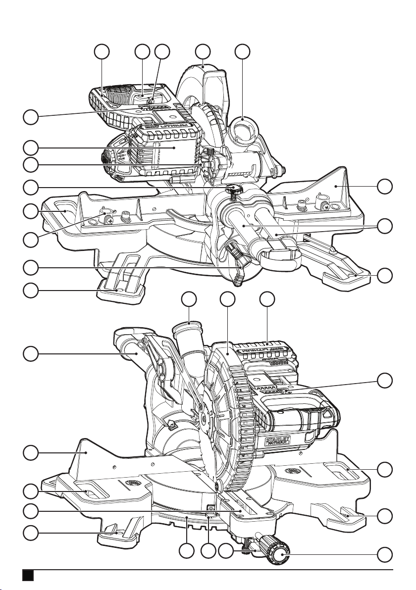
Features
This tool includes some or all of the following features.
1. Trigger switch
2. Operating handle
3. Mounting holes
4. Lower Guard
5. Mitre locking knob
6. Mitre latch button
7. Kerf plate
8. Mitre scale
9. Mitre scale indicator
10. Carry grips
11. Fence
12. Bevel lock knob
13. Rails
13a.Velcro strap
14. Dust port
15. Battery pack
16. Work light switch
17. Lock off lever
18. Rail lock screw
19. Clamp mounting hole
20. Lock down pin
Assembly (Fig. A)
Your mitre saw is part assembled in the carton.
uOpen the box and lift the saw out by using the carry grips
(10) in the base of the saw (Fig. A).
u Place the saw on a smooth, at surface such as a work-
bench or strong table.
u Examine Assembly diagram on page 2 of this manual to
become familiar with the saw and its various parts. The
section on adjustments will refer to these terms and you
must know what and where the parts are.
u The mitre locking knob (5) is not assembled for shipping.
Remove the mitre locking knob (5) from the packaging
and screw onto the saw, see gure G and J for position.
u Your saw has a built-in dust port (14) that allows either
the supplied, but not assembled, dust bag (35) or shop
vacuum system to be connected (Fig. N).
Kerf plate (Fig. J)
The kerf plate (7) is mounted to the table by 6 screws. The
kerf plate (7) height is not adjustable.
Note: If the kerf plate (7) is worn, damaged or needs to be
replaced, repairs should be carried out by authorised repair
agents or Stanley Fat Max service staff.
Lock down pin (Fig. F)
Warning! The lock down pin should be used ONLY when
carrying or storing the saw. NEVER use the lock down pin for
any cutting operation.
Note: To lift, carry and support the mitre saw during transport
use the two carrying handles (10) located on both sides of the
mitre saw base (Fig. A).
To lock the saw head in the down position, push the saw head
down, push the lock down pin (20) in and release the saw
head. This will hold the saw head safely down for transporting
the saw from place to place. To release, press the saw head
down and pull the pin out.
Warning! Always be sure that the tool is switched off and the
battery is removed from the tool before adjusting or checking
the tools function.
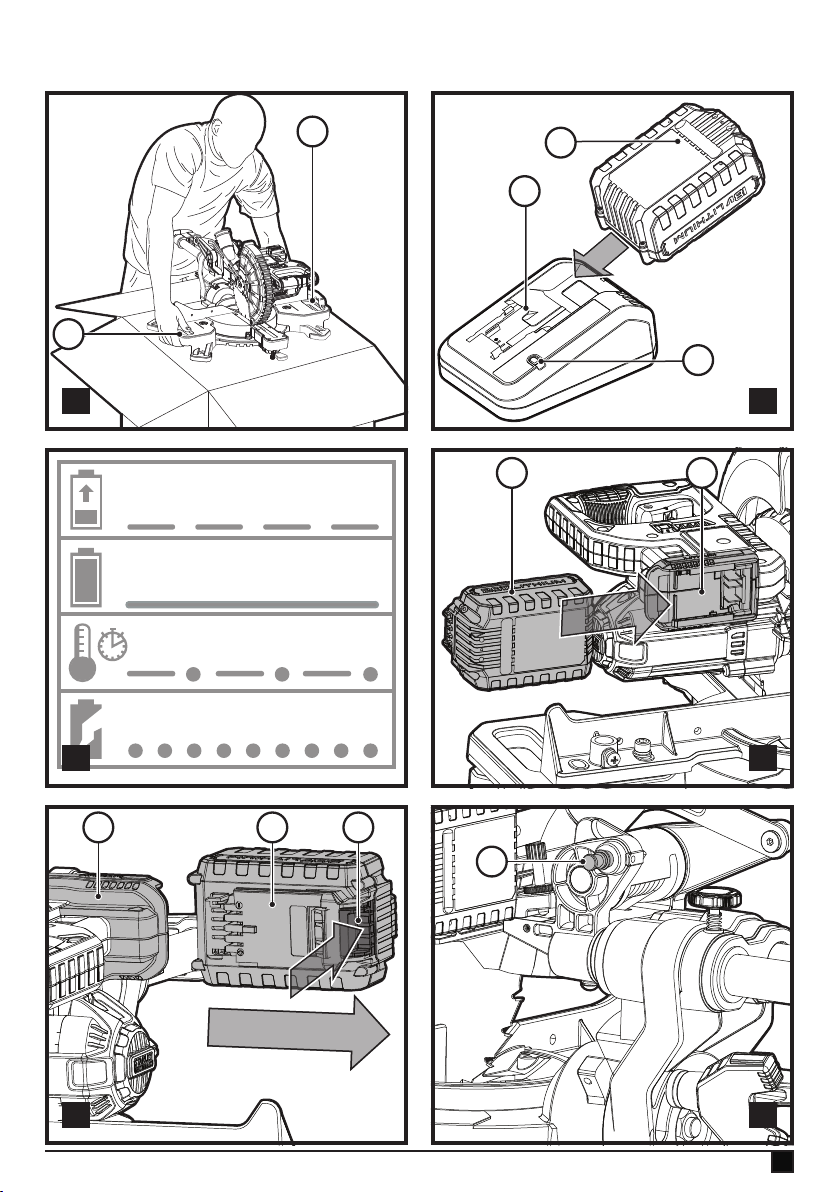
Charging a battery (g. B)
Stanley FatMax chargers are designed to charge Stanley
FatMax battery packs.
u Plug the charger (21) into an appropriate outlet before
inserting a battery pack (15).
u Insert the battery pack (15) into the charger, making sure
the battery pack is fully seated in the battery slots
(Figure B).
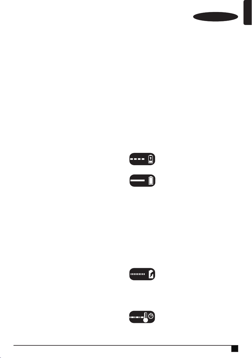
The LED (21a) will ash indicating that the
battery is being charged.
The completion of charge is indicated by the
LED remaining on continuously. The pack is
fully charged and may be used at this time or
left in the charger.
u Recharge discharged batteries as soon as possible after
use or battery life may be greatly diminished.
u For longest battery life, do not discharge batteries fully.
It is recommended that the batteries be recharged after
each use.
Charger diagnostics (g. C)
This charger is designed to detect certain problems that can
arise with the battery packs or the power source. Problems
are indicated by one LED ashing in different patterns.
Bad battery
The charger can detect a weak or damaged
battery. The LED ashes in the pattern indi-
cated on the label. If you see this bad battery
blink pattern, do not continue to charge the battery. Return it
to a service centre or a collection site for recycling.
Hot/cold pack delay
When the charger detects a battery that
is excessively hot or excessively cold, it
automatically starts a Hot/Cold Pack Delay,
suspending charging until the battery has normalized. After
this happens, the charger automatically switches to the Pack
13
Page 14

ENGLISH
(Original instructions)
Charging mode. This feature ensures maximum battery life.
The light ashes in the pattern indicated on the label.
Leaving the battery in the charger
The charger and battery pack can be left connected with the
LED glowing indenitely. The charger will keep the battery
pack fresh and fully charged.
This charger features an automatic tune-up mode which
equals or balances the individual cells in the battery pack to
allow it to function at peak capacity.
Battery packs should be tuned up weekly or whenever the battery no longer delivers the same amount of work. To use the
automatic tune-up mode, place the battery pack in the charger
and leave it for at least 8 hours.
Important charging notes
u Longest life and best performance can be obtained if
the battery pack is charged when the air temperature is
between 18 °C – 24 °C. DO NOT charge the battery pack
in an air temperature below +4.5 °C, or above +40 °C.
This is important and will prevent serious damage to the
battery pack.
u The charger and battery pack may become warm to the
touch while charging. This is a normal condition, and does
not indicate a problem.
u To facilitate the cooling of the battery pack after use, avoid
placing the charger or battery pack in a warm environment
such as in a metal shed or an un-insulated trailer.
u If the battery pack does not charge properly:
u Check operation of receptacle by plugging in a lamp or
other appliance;
u Check to see if receptacle is connected to a light switch
which turns power off when you turn out the lights;
u Move the charger and battery pack to a location where
the surrounding air temperature is approximately 18 °C
– 24 °C;
u If charging problems persist, take the tool, battery pack
and charger to your local service centre.
u The battery pack should be recharged when it fails to
produce sufcient power on jobs which were easily done
previously. DO NOT CONTINUE to use under these
conditions. Follow the charging procedure. You may also
charge a partially used pack whenever you desire with no
adverse effect on the battery pack.
u Foreign materials of a conductive nature such as, but
not limited to, grinding dust, metal chips, steel wool,
aluminium foil, or any buildup of metallic particles should
be kept away from charger cavities. Unplug the charger
before attempting to clean.
u Do not freeze or immerse the charger in water or any
other liquid.
Fitting and removing the battery (g. D, E)
u To t the battery (15), line it up with the receptacle on the
tool (22). Slide the battery into the receptacle and push
until the battery snaps into place.
u To remove the battery, push the battery release button
(15a) while at the same time pulling the battery out of the
receptacle as shown in gure E.
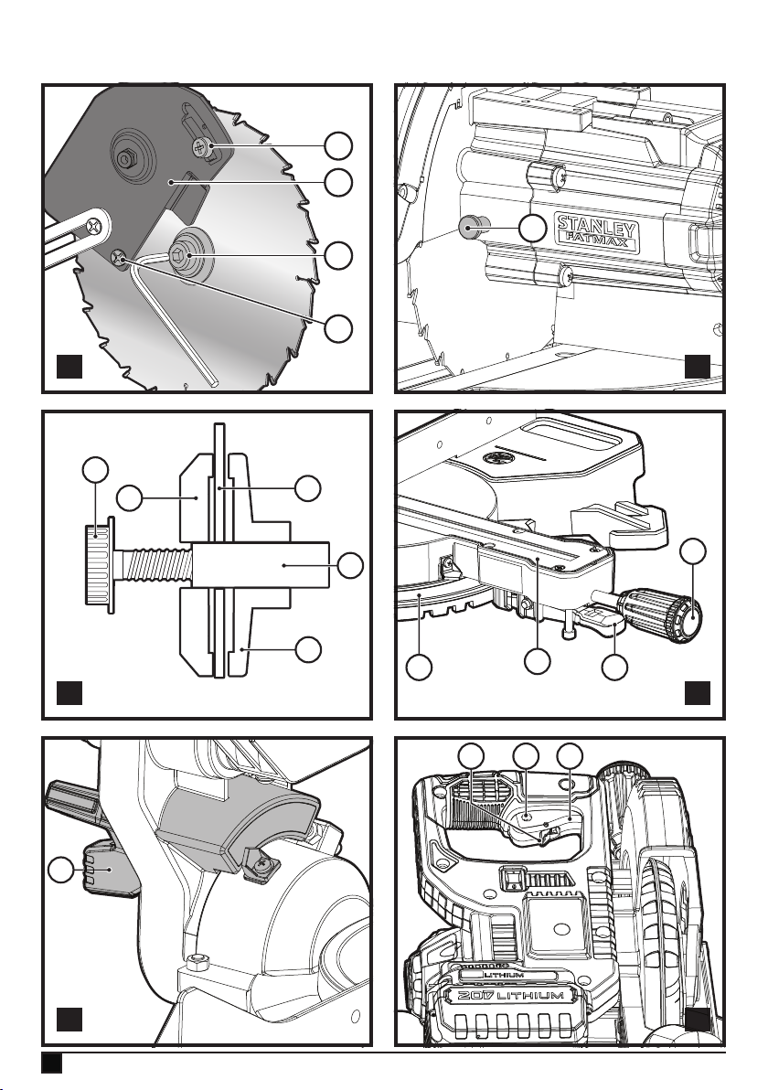
Changing or Installing a New Saw Blade
(Fig. G, H, I)
Warning! To reduce the risk of serious personal injury, turn
tool off and remove the battery pack before transporting,
making any adjustments or removing/installing attachments or
accessories. An accidental start-up can cause injury.
Removing the Blade
u Remove battery pack (15) from the saw.
u Raise the arm to the upper position and raise the lower
guard (4) as far as possible.
u Loosen, but do not remove the guard bracket front screw
(24) until the bracket (25) can be raised far enough to
access the blade screw (26). Lower guard will remain
raised due to the position of the guard bracket screw.
u Depress the spindle lock button (28) while carefully rotat-
ing the saw blade (29) by hand until the lock engages.
u Keeping the button depressed, use the other hand and the
hex side of the wrench provided to loosen the blade screw
(26). (Turn clockwise, left-hand threads.)
u Remove the blade screw (26) using the hex side of the
wrench provided, the outer clamp washer (30) and blade
(29). The inner clamp washer (31) may be left on the
spindle (32).
Installing a Blade
u Remove battery pack (15) from the saw.
u With the arm raised, the lower guard (4) held open and
the guard bracket (25) raised, place the blade (29) on the
spindle (32) and against the inner blade clamp (31) with
the teeth on the blade pointing in the direction of rotation
as marked on the saw.
u Assemble the outer clamp washer (30) onto the spindle
(32).
u Install the blade screw (26) and, engaging the spindle lock
(28), tighten the screw (26) rmly with wrench provided
(turn counterclockwise, left-hand threads).
u Return the guard bracket (25) to its original full down posi-
tion and rmly tighten the guard bracket screw (24) to hold
bracket in place.
Cut line guidance system
Warning! Do not stare into work light. Serious eye injury could
result.
14
Page 15

(Original instructions)
ENGLISH
Note: The battery must be charged and connected to the
mitre saw.
The cut line guidance system can only be turned On or Off by
the work light switch (16).
To cut through an existing pencil line on a piece of wood, turn
on the cut line guidance system using the work light switch
(16) (not with the main trigger), then pull down on the operating handle (2) to bring the saw blade close to the wood.
The shadow of the blade will appear on the wood. This
shadow line represents the material that the blade will remove
when performing a cut.
To correctly locate your cut to the pencil line, align the pencil
line with the edge of the blade’s shadow. Keep in mind that
you may have to adjust the mitre or bevel angles in order to
match the pencil line exactly.
Your saw is equipped with a battery fault feature. The work
light begins to ash when the battery is near the end of its
useful charge, or when the battery is too hot. Charge the battery prior to continuing cutting applications. Refer to charging
procedure under Important safety instructions for battery
packs for battery charging instructions.
Mitre control (Fig. J)
The mitre lock knob (5) and mitre latch button (6) allow you
to mitre your saw to 47° right and 47° left. The mitre latch will
automatically locate at 0˚, 15˚, 22.5˚, 31.6˚ and 45˚ both left
and right. To mitre the saw, unlock the mitre lock mechanism
by turning the mitre lock knob (5) anti clockwise to unlock and
clockwise to lock. Pull the mitre latch button (6) up, and set
the mitre angle desired on the mitre scale (8). Lock the mitre
lock knob (5) by turning clockwise.
Bevel Lock Knob (Fig. K)
The bevel lock allows you to bevel the saw 48° to the left.
To adjust the bevel setting, turn the bevel lock knob (12)
counterclockwise to loosen. To tighten, turn the bevel lock
knob clockwise.
Caution! Pinch hazard. Be sure to tighten bevel lock knob
before adjusting overrides.
Trigger Switch (Fig. L)
To turn the saw on, push the lock-off lever (17) to the left,
then depress the trigger switch (1). The saw will run while
the switch is depressed. Allow the blade to spin up to full
operating speed before making the cut. To turn the saw off,
release the switch. Allow the blade to stop before raising the
saw head. There is no provision for locking the switch on. A
hole (1a) is provided in the trigger for insertion of a padlock to
lock the switch off.
Your saw is not equipped with an automatic electric blade
brake, but the saw blade should stop within 5 seconds of trig-
ger release. This is not adjustable. If the stop time repeatedly
exceeds 5 seconds, have the tool serviced by an authorised
Stanley FatMax service centre.
Always be sure the blade has stopped before removing it from
the kerf.
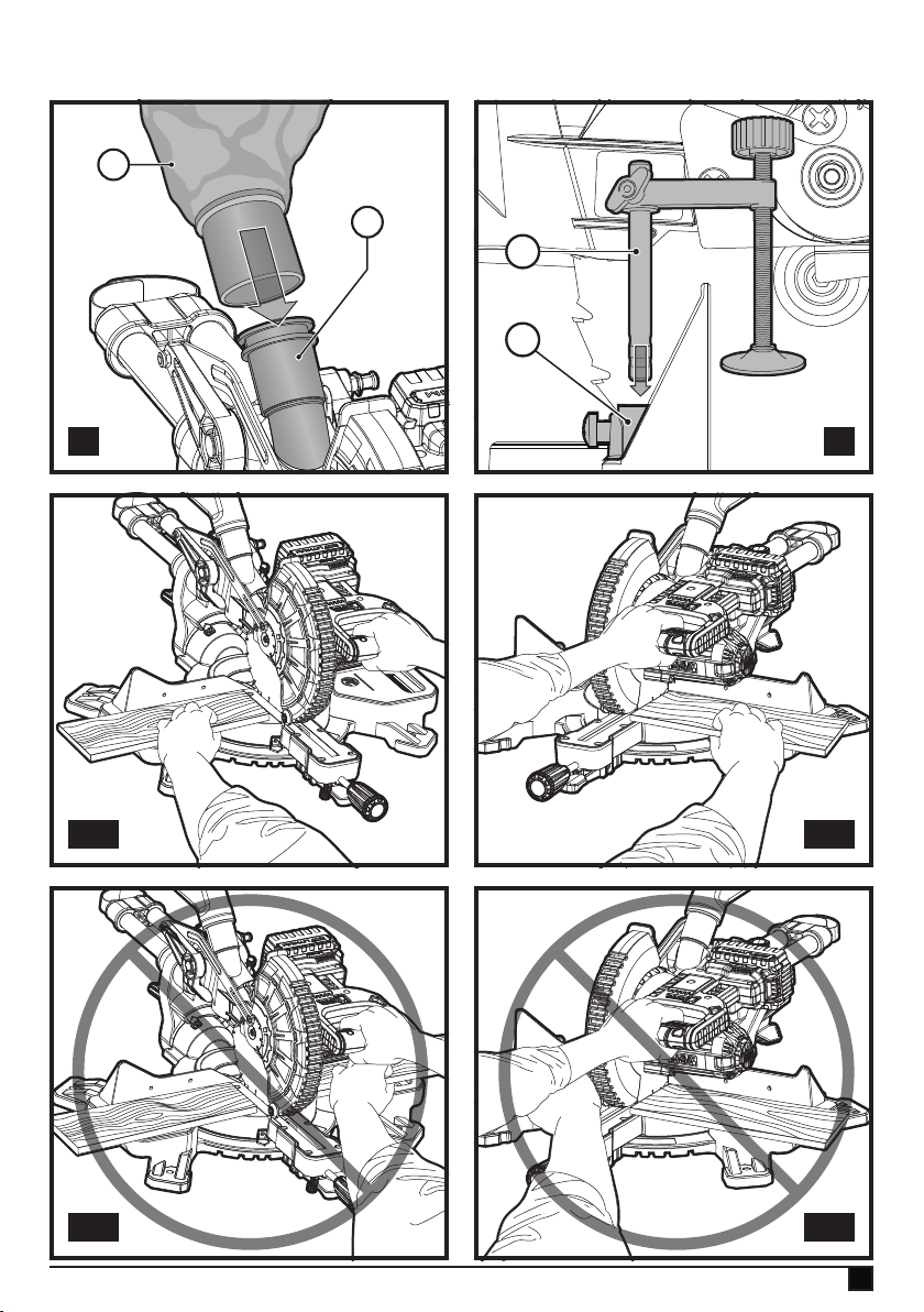
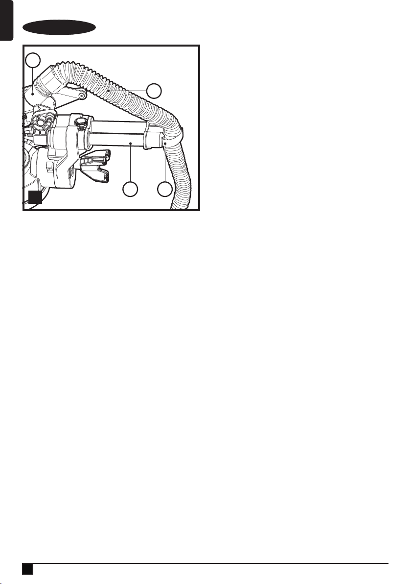
Dust Extraction (Fig. M)
Warning! To reduce the risk of serious personal injury, turn
tool off and remove the battery pack before transporting,
making any adjustments or removing/installing attachments or
accessories. An accidental start-up can cause injury.
Your saw has a built-in dust port (14) that allows either the
supplied dust bag (35) or a shop vacuum system to be
connected.
To attach the dust bag
u Fit the dust bag (35) to the dust port (14) as shown in
Figure M.
u A vacuum tube (38 - not provided) can be tted to the dust
port (14) rather than the dust bag (35). This can be done
by tting your vacuum tube (38) in place of the dust bag
(35), see gure M.
u Use the velcro strap (13a) to hold your vacuum tube (38)
clear from the sliding rails (13) whilst operating the saw.
Note: The velcro strap (13a) is not a carrying handle and
should not be used to move or transport the saw.
To empty the dust bag
uRemove dust bag (35) from the saw and gently shake or
tap the dust bag to empty.
u Reattach the dust bag back onto the dust port (14).
You may notice that all the dust will not come free from the
bag. This will not affect cutting performance but will reduce
the saw's dust collection efciency. To restore your saw's dust
collection efciency, depress the spring inside the dust bag
when you are emptying it and tap it on the side of the trash
can or dust receptacle.
Warning! Never operate this saw unless the dust bag is in
place. Wood dust may create a breathing hazard.
Cutting with your saw
If the slide feature is not used, ensure the saw head is
pushed back as far as possible and the rail lock screw (18) is
tightened. This will prevent the saw from sliding along its rails
as the workpiece is engaged.
Note: DO NOT CUT FERROUS METALS OR MASONRY
WITH THIS SAW (NON FERROUS METALS CAN BE CUT
BY THIS SAW. Do not use any abrasive blades.
Note: Refer to guard actuation and visibility in the adjustments
section for important information about the lower guard before
cutting.
15
Page 16

ENGLISH
(Original instructions)
Crosscuts (g. N)
A crosscut is made by cutting wood across the grain at any
angle. A straight crosscut is made with the mitre arm at the
zero degree position. Set and lock the mitre arm at zero, hold
the wood rmly on the table and against the fence. With the
rail lock screw (18) tightened, turn on the saw by squeezing
the trigger switch (1).
When the saw comes up to speed (about 1 second) lower
the arm smoothly and slowly to cut through the wood. Let the
blade come to a full stop before raising arm.
When cutting anything larger than a 2 x 4 (51 x 102), use an
out-down-back motion with the rail lock screw (18) loosened.
Pull the saw out, toward you, lower the saw head down toward
the work piece, and slowly push the saw back to complete the
cut. Do not allow the saw blade to contact the top of the work
piece while pulling out. The saw may run toward you, possibly
causing personal injury or damage to the work piece.
Warning! Always use a work clamp to maintain control and
reduce the risk of work piece damage and personal injury, if
your hands are required to be within 6" (152 mm) of the blade
during the cut.
Note! The rail lock screw (18) must be loose to allow the saw
to slide along its rails.
Mitre crosscuts are made with the mitre arm at some angle
other than zero.
This angle is often 45º for making corners, but can be set
anywhere from zero to 47º left or 47° right. Make the
cut as described above.
When performing a mitre cut on work pieces wider than a 2
x 6 that are shorter in length, always place the longer side
against the fence (Fig. O).
To cut through an existing pencil line on a piece of wood,
match the angle as close as possible. Cut the wood a little too
long and measure from the pencil line to the cut edge to deter-
mine which direction to adjust the mitre angle and recut. This
will take some practice, but it is a commonly used technique.
Bevel cuts
A bevel cut is a crosscut made with the saw blade leaning at
an angle to the wood. In order to set the bevel, loosen the
bevel lock knob (12), and move the saw to the left as desired.
Once the desired bevel angle has been set, tighten the bevel
lock rmly. Bevel angles can be set from 3º right to 48º left.
Quality of cut
The smoothness of any cut depends on a number of variables.
Things like material being cut, blade type, blade sharpness
and rate of cut all contribute to the quality of the cut. When
smoothest cuts are desired for moulding and other precision
work, a sharp (60 tooth carbide tip) blade and a slower, even
cutting rate will produce the desired results.
16
Ensure that the material does not move or creep while cutting;
clamp it securely in place.
Always let the blade come to a full stop before raising arm. If
small bres of wood still split out at the rear of the work piece,
stick a piece of masking tape on the wood where the cut will
be made. Saw through the tape and carefully remove tape
when nished.
For varied cutting applications, refer to the list of recommend-
ed saw blades for your saw and select the one that best ts
your needs. Refer to Saw Blades under Optional Accessories.
Body and hand position (g. O1–O4)
Proper positioning of your body and hands when operating the
mitre saw will make cutting easier, more accurate and safer.
Never place hands near cutting area. Place hands no closer
than 6" (152 mm) from the blade. Hold the work piece tightly
to the table and the fence when cutting. Keep hands in position until the trigger has been released and the blade has
completely stopped.
ALWAYS MAKE DRY RUNS (UN-POWERED) BEFORE
FINISH CUTS SO THAT YOU CAN CHECK THE PATH OF
THE BLADE. DO NOT CROSS HANDS, AS SHOWN IN
FIGURE O3.
Keep both feet rmly on the oor and maintain proper balance. As you move the mitre arm left and right, follow it and
stand slightly to the side of the saw blade. Sight through the
guard louvres when following a pencil line.
Clamping the work piece
Warning! To reduce the risk of serious personal injury, turn
tool off and remove the battery pack before transporting,
making any adjustments or removing/installing attachments or
accessories. An accidental start-up can cause injury.
Warning! A work piece that is clamped, balanced and secure
before a cut may become unbalanced after a cut is completed.
An unbalanced load may tip the saw or anything the saw is
attached to, such as a table or workbench. When making a
cut that may become unbalanced, properly support the work
piece and ensure the saw is rmly bolted to a stable surface.
Personal injury may occur.
Warning! The clamp foot must remain clamped above the
base of the saw whenever the clamp is used. Always clamp
the work piece to the base of the saw – not to any other part
of the work area. Ensure the clamp foot is not clamped on the
edge of the base of the saw.
Warning! Always use a work clamp to maintain control and
reduce the risk of work piece damage and personal injury, if
your hands are required to be within 6" (152 mm) of the blade
during the cut. If you cannot secure the work piece on the
table and against the fence by hand (irregular shape, etc.), or
Page 17

(Original instructions)
ENGLISH
your hand would be less than 6" (152 mm) from the blade, a
clamp or other xture must be used.
Use the material clamp provided with your saw. To purchase
a material clamp, contact your local retailer or Stanley FatMax
service centre.
Other aids such as spring clamps, bar clamps or C-clamps
may be appropriate for certain sizes and shapes of material.
Use care in selecting and placing these clamps. Take time to
make a dry run before making the cut.
To install clamp (g. P)
u Insert the clamp (37) into the hole (19) behind the fence.
The clamp should be facing toward the back of the mitre
saw. The groove on the clamp rod should be fully inserted
into the base. Ensure this groove is fully inserted into the
base of the mitre saw. If the groove is visible, the clamp
will not be secure.
u Rotate the clamp 180º toward the front of the mitre saw.
u Loosen the knob to adjust the clamp up or down, then use
the ne adjust knob to rmly clamp the work piece.
Note: Place the clamp on the opposite side of the base when
bevelling. ALWAYS MAKE DRY RUNS (UN-POWERED) BEFORE FINISH CUTS TO CHECK THE PATH OF THE BLADE.
ENSURE THE CLAMP DOES NOT INTERFERE WITH THE
ACTION OF THE SAW OR GUARDS.
Adjustments
Your mitre saw is fully and accurately adjusted at the factory at
the time of manufacture. If readjustment due to shipping and
handling or any other reason is required, follow the instruc-
tions below to adjust your saw.
Once made, these adjustments should remain accurate. Take
a little time now to follow these directions carefully to maintain
the accuracy of which your saw is capable.
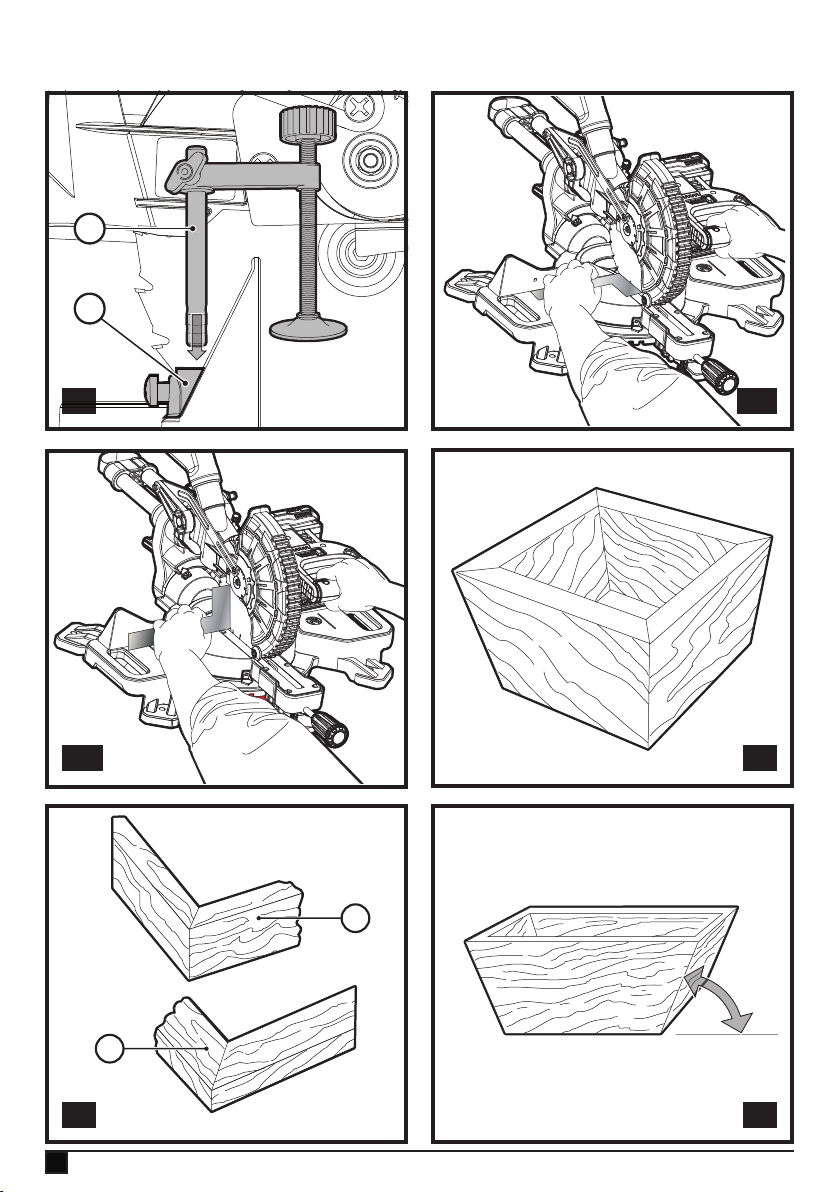
Mitre scale adjustment (g. Q1)
Lock the arm in the down position. Unlock the mitre lock
knob (5) and swing the mitre arm until the mitre latch button
(6) locks it at the 0° mitre position. Do not lock the mitre lock
knob. Place a square against the saw’s fence and blade,
as shown. (Do not touch the tips of the blade teeth with the
square. To do so will cause an inaccurate measurement.) If
the saw blade is not exactly perpendicular to the fence, loosen
and move the material fence until the blade is perpendicular
to the fence, as measured with the square. Pay no attention to
the reading of the mitre pointer at this time.
Bevel square to table adjustment (Fig. Q2)
To align the blade square to the table, lock the arm in the
down position with the lock down pin (20). Place a square
against the blade, ensuring the square is not on top of a tooth.
Loosen the bevel lock knob (5) and ensure the arm is rmly
against the 0° bevel stop. Rotate the 0° bevel adjustment
screw with the 1/2" (12.7 mm) socket (not provided) as neces-
sary so that the blade is at 0° bevel to the table, as measured
with the square.
Guard actuation and visibility (Fig. V)
Warning! Pinch hazard. To reduce the risk of injury, keep
thumb underneath the operating handle when pulling the
handle down. The lower guard will move up as the operating
handle is pulled down, which could cause pinching.
The lower guard (4) on your saw has been designed to automatically uncover the blade when the arm is brought down
and to cover the blade when the arm is raised.
Before each use or after making adjustments, cycle the arm
(un-powered) and make sure the guard opens smoothly and
closes fully. It should not contact the blade. With the arm
up, raise the guard (un-powered) as shown in Figure V and
release. The guard should fully close rapidly.
Do not operate the saw if the guard does not move freely and
fully close rapidly. Never clamp or tie the guard in an open
position when operating the saw.
The guard can be raised by hand when installing or removing
saw blades or for inspection of the saw.
NEVER RAISE THE LOWER GUARD MANUALLY UNLESS
THE BLADE IS STOPPED.
Note: Certain special cuts of large material will require that
you manually raise the guard. Refer to cutting large material
under special cuts.
The front section of the guard is louvred for visibility while
cutting. Although the louvres dramatically reduce ying debris,
they are openings in the guard and safety glasses should
be worn at all times.
Rail Guide
Periodically check the rails (13) for any play or clearance. The
rails can be cleaned with a dry clean cloth.
Cutting Picture Frames, Shadow Boxes And Other
Four-Sided Projects (Fig. R1, R2)
To best understand how to make the items listed here, we
suggest that you try a few simple projects using scrap wood
until you develop a “feel” for your saw.
Your saw is the perfect tool for mitreing corners like the one
shown in Figure R1. Sketch A in Figure R2 shows a joint made
by using the bevel adjustment to bevel the edges of the two
boards at 45º each to produce a 90º corner. For this joint the
mitre arm was locked in the zero position and the bevel ad-
justment was locked at 45º. The wood was positioned with the
broad at side against the table and the narrow edge against
the fence. The cut could also be made by mitreing right and
left with the broad surface against the fence.
17
Page 18
ENGLISH
(Original instructions)
Cutting trim moulding and other frames (g. R2)
Sketch B in Figure R2 shows a joint made by setting the mitre
arm at 45º to mitre the two boards to form a 90º corner. To
make this type of joint, set the bevel adjustment to zero and
the mitre arm to 45º. Once again, position the wood with the
broad at side on the table and the narrow edge against the
fence.
Figures R1 and R2 are for four-sided objects only.
As the number of sides changes, so do the mitre and bevel
angles. The chart below gives the proper angles for a variety
of shapes.
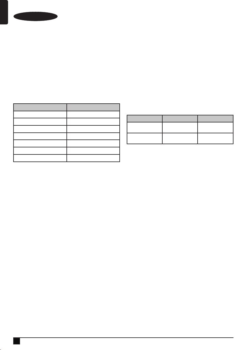
Examples
Number of Sides Mitre or Bevel Angle
4 45°
5 36°
6 30°
7 25.7°
8 22.5°
9 20°
10 18°
The chart assumes that all sides are of equal length. For a
shape that is not shown in the chart, use the following formula:
180º divided by the number of sides equals the mitre (if the
material is cut vertically) or bevel angle (if the material is cut
laying at).
Cutting compound mitres (g. R3)
A compound mitre is a cut made using a mitre angle and a
bevel angle at the same time. This is the type of cut used to
make frames or boxes with slanting sides like the one shown
in gure R3.
Note: If the cutting angle varies from cut to cut, check that
the bevel lock knob and the mitre lock handle are securely
locked. These must be locked after making any changes in
bevel or mitre. The chart at the end of this manual (Table 1)
will assist you in selecting the proper bevel and mitre settings
for common compound mitre cuts. To use the chart, select the
desired angle A (Fig. R3) of your project and locate that angle
on the appropriate arc in the chart. From that point follow the
chart straight down to nd the correct bevel angle and straight
across to nd the correct mitre angle.
Set your saw to the prescribed angles and make a few trial
cuts. Practice tting the cut pieces together until you develop
a feel for this procedure and feel comfortable with it.
Example: To make a 4-sided box with 26º exterior angles
(Angle A, Fig. R3), use the upper right arc. Find 26° on the arc
scale. Follow the horizontal intersecting line to either side to
get mitre angle setting on saw (42°). Likewise, follow the
18
vertical intersecting line to the top or bottom to get the bevel
angle setting on the saw (18°). Always try cuts on a few scrap
pieces of wood to verify the settings on the saw.
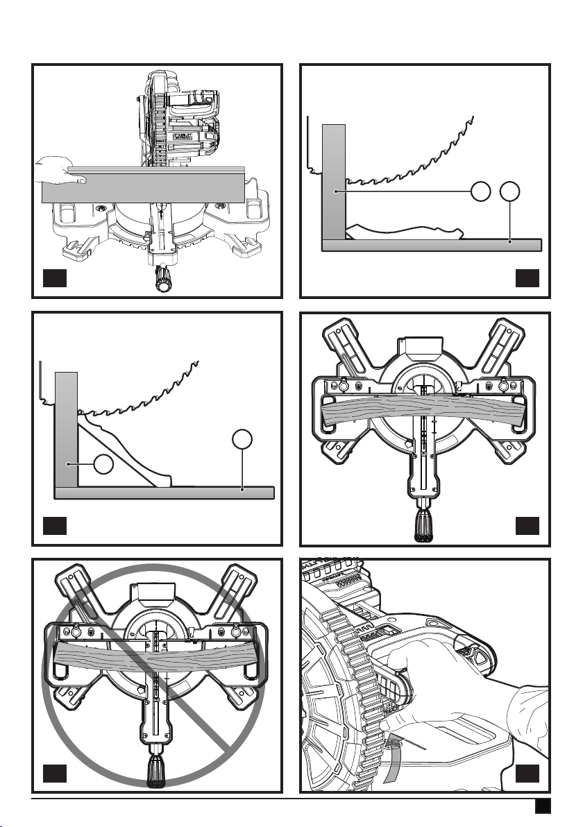
Cutting base moulding (g. S)
Straight 90º cuts:
Position the wood against the fence and hold it in place as
shown in Figure S. Turn on the saw, allow the blade to reach
full speed and lower the arm smoothly through the cut.
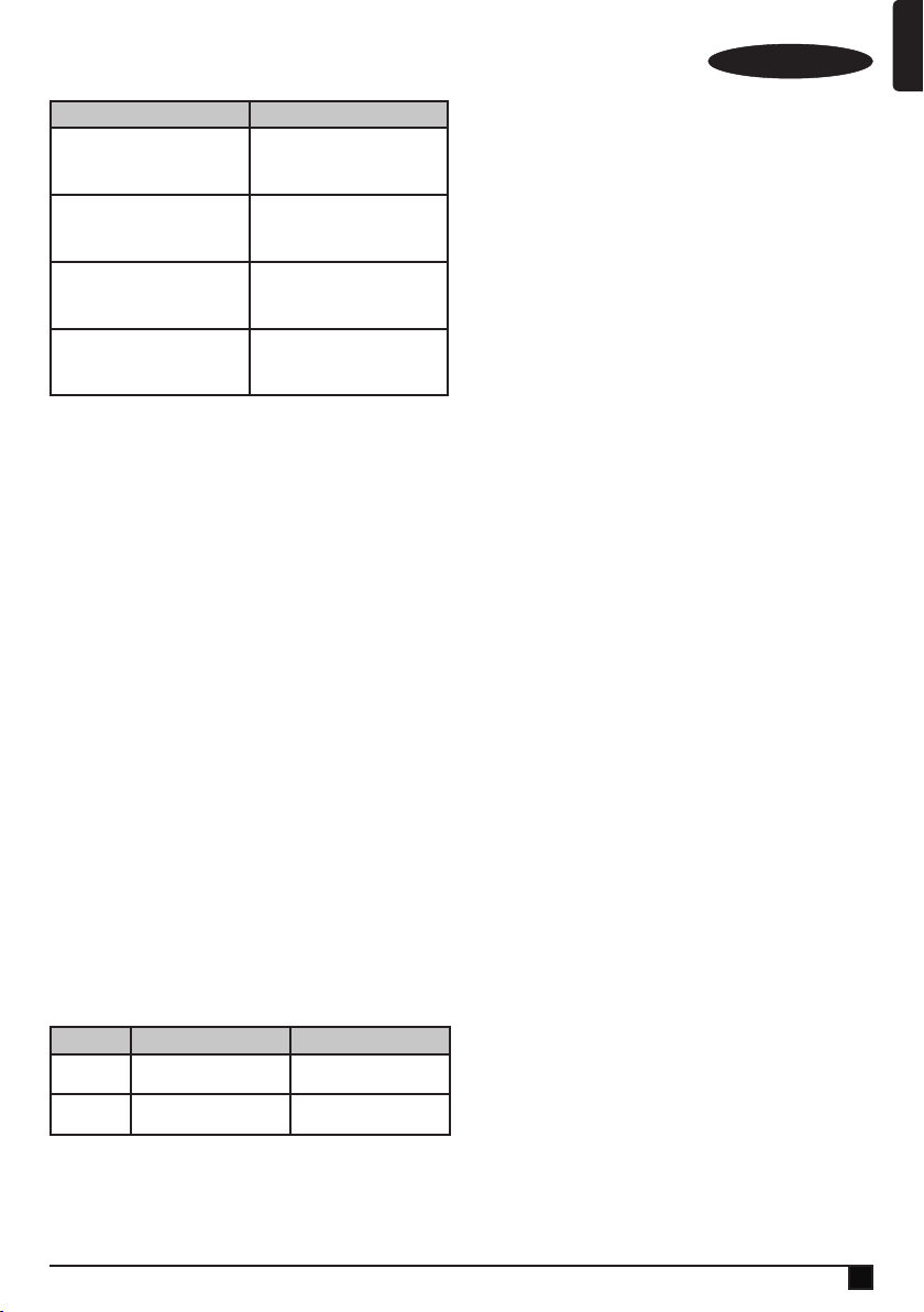
Cutting base moulding up to 3.5" (90 mm) high
vertically against the Fence
Position material as shown in Figure S. All cuts should be
made with the back of the moulding against the fence and with
the bottom of the moulding against the table.
Inside Corner Outside Corner
Left Side
Right Side
Mitre left 45°
Save left side of cut
Mitre right 45°
Save right side of cut
Mitre right 45°
Save left side of cut
Mitre left 45°
Save right side of cut
Material up to 3.5" (90 mm) can be cut as described above.
Cutting crown moulding
In order to t properly, crown moulding must be compound
mitred with extreme accuracy.
The two at surfaces on a given piece of crown moulding are
at angles that, when added together, equal exactly 90°. Most,
but not all, crown moulding has a top rear angle (the section
that ts at against the ceiling) of 52° and a bottom rear angle
(the part that ts at against the wall) of 38°.
Your mitre saw has special preset mitre detent points at 31.6°
left and right for cutting crown moulding at the proper angle.
There is also a mark on the bevel scale at 33.8°.
The Bevel Setting/Type of Cut chart gives the proper settings
for cutting crown moulding. (The numbers for the mitre and
bevel settings are very precise and are not easy to accurately
set on your saw.) Since most rooms do not have angles of
precisely 90°, you will have to ne tune your settings anyway.
Instructions for cutting crown moulding laying at
and using the compound features
u Lay the moulding with broad back surface down at on
saw table (36) (g. T1).
u The settings below are for all Standard crown moulding
with 52° and 38° angles.
Page 19
(Original instructions)
ENGLISH
Bevel Setting Type Of Cut
LEFT SIDE, INSIDE CORNER:
33.8°
33.8°
33.8°
33.8°
1. Top of moulding against fence
2. Mitre table set right 31.62°
3. Save left end of cut
RIGHT SIDE, INSIDE CORNER:
1. Bottom of moulding against fence
2. Mitre table set left 31.62°
3. Save left end of cut
LEFT SIDE, OUTSIDE CORNER:
1. Bottom of moulding against fence
2. Mitre table set left 31.62°
3. Save right end of cut
RIGHT SIDE, OUTSIDE CORNER:
1. Top of moulding against fence
2. Mitre table set right 31.62°
3. Save right end of cut
Note: When setting bevel and mitre angles for all compound
mitres, remember that the angles presented for crown
mouldings are very precise and difcult to set exactly. Since
they can easily shift slightly and very few rooms have exactly
square corners, all settings should be tested on scrap
moulding.
Alternative method for cutting crown moulding
Place the moulding at an angle between the fence (11) and
the saw table (36), with the top side of the moulding on the
table and the bottom side of the moulding on the fence as
shown in gure T1.
The advantage to cutting crown moulding using this method
is that no bevel cut is required. Minute changes in the mitre
angle can be made without affecting the bevel angle. This
way, when corners other than 90º are encountered, the saw
can be quickly and easily adjusted for them.
Instructions for cutting crown moulding angled
between the fence and base of the saw for all cuts
This saw can cut up to 9/16" (14 mm) x 3-5/8" (92 mm) crown
moulding nested.
u Angle the moulding so the bottom of the moulding (part
which goes against the wall when installed) is against the
fence (11) and the top of the moulding is resting on the
saw table (36), as shown in gure T2.
u The angled “ats” on the back of the moulding must rest
squarely on the fence and saw table (36).
Inside Corner Outside Corner
Left Side
Right Side
Mitre right at 45°
Save right side of cut
Mitre left at 45°
Save left side of cut
Mitre left at 45°
Save right side of cut
Mitre right at 45°
Save left side of cut
Bowed material (g. U1, U2)
When cutting bowed material always position it as shown in
gure U1 and never like that shown in gure U2. Positioning
the material incorrectly will cause it to pinch the blade near
the completion of the cut.
Cutting round material
Rounded material should be clamped or held rmly to the
fence to keep It from rolling. This is extremely important when
making angle cuts.
Cutting large material (g. V)
Occasionally you will encounter a piece of wood a little too
large to t beneath the lower guard. To clear the guard over
the wood, with the saw off and your right hand on the operating handle, place your right thumb outside of the upper portion
of the guard and roll the guard up just enough to clear the
wood, as shown in gure V. Release the guard prior to starting
the motor. The guard mechanism will function properly during
the cut. Only do this when necessary.
NEVER TIE, TAPE, OR OTHERWISE HOLD THE GUARD
OPEN WHEN OPERATING THIS SAW.
Maintenance
Warning! To reduce the risk of serious personal injury, turn
tool off and remove the battery pack before transporting,
making any adjustments or removing/installing attachments or
accessories. An accidental start-up can cause injury.
Warning! To reduce the risk of serious personal injury, DO
NOT touch the sharp points on the blade with ngers or hands
while performing any maintenance.
DO NOT use lubricants or cleaners (particularly spray or
aerosol) in the vicinity of the plastic guard. The polycarbon-
ate material used in the guard is subject to attack by certain
chemicals.
u All bearings are sealed. They are lubricated for life and
need no further maintenance.
u Periodically clean all dust and wood chips from around
AND UNDER the base and the rotary table. Even though
slots are provided to allow debris to pass through, some
dust will accumulate.
u The brushes are designed to give you several years of
use. If they ever need replacement, return the tool to the
nearest service centre for repair.
Special Cuts
Never make any cut unless the material is secured on the
table and against the fence.
19
Page 20
ENGLISH
(Original instructions)
Troubleshooting
Problem Possible Cause Solution
Install battery. Refer to Installing
and Removing Battery Pack.
Charge battery. Refer to Charging
Procedure.
Have brushes replaced by
authorised service centre.
Replace blade. Refer to Changing
or Installing a New Saw Blade.
Turn blade around. Refer to
Changing or Installing a New Saw
Blade.
Remove blade and clean with
coarse steel wool and turpentine or
household oven cleaner.
Change the blade type.
Charge battery. Refer to Charging
Procedure.
Tighten all mounting hardware.
Refer to Bench Mounting
Reposition on at level surface.
Replace blade. Refer to Changing
or Installing a New Saw Blade.
Check and adjust. Refer to Mitre
Scale Adjustment under
Adjustments.
Check and adjust. Refer to Mitre
Scale Adjustment under
Adjustments.
Check and adjust fence. Refer to
Bevel Square to Table Adjustment
under Adjustments.
Clamp work piece securely to fence
or glue 120 grit sandpaper to fence
with rubber cement.
Take to authorised service centre.
Refer to Bowed Material under
Special Cuts.
Saw will not
start.
Saw makes
unsatisfactory
cuts.
Work light is
ashing.
Machine
vibrates
excessively.
Does not
make accurate
mitre cuts.
Material
pinches blade.
Battery not installed.
Battery not charged.
Brushes worn out
Dull blade.
Blade mounted
backwards.
Gum or pitch on
blade.
Incorrect blade for
work being done.
Battery not charged
Saw not mounted
securely to stand or
work bench.
Stand or bench on
uneven oor.
Damaged saw
blade.
Mitre scale not
adjusted correctly.
Blade is not square
to fence.
Blade is not
perpendicular to
table.
Work piece moving
Kerf plate worn or
damaged.
Cutting bowed
material.
Protecting the environment
Separate collection. Products and batteries marked
with this symbol must not be disposed of with normal
Z
household waste.
Products and batteries contain materials that can be recovered or recycled reducing the demand for raw materials.
Please recycle electrical products and batteries according to
local provisions. Further information is available at
www.2helpU.com
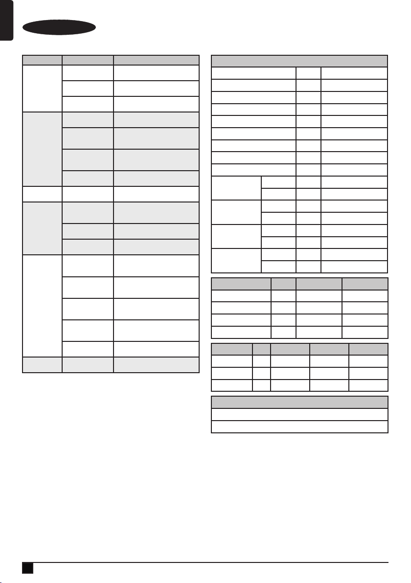
Technical data
FMCS701 (H1)
Voltage V 18
Speed /min 3,800
Blade outer diameter mm 190
Bore diameter mm 16
Blade max. kerf mm 1.8
Weight without battery kg 10
Blade thickness mm 1.0
Mitre (max. positions) ° 47
Bevel (max. positions) ° 47
0 deg. mitre
45 deg. mitre right
45 deg. mitre left
45 deg. bevel left
Charger 905998** typ. 1 906086** typ. 1
Input voltage V
Output voltage V
Output current A 1 2
Approx. charge time Mins 90 - 240 45 - 120
Battery FMC689L FMC687L FMC688L
Voltage V
Capacity Ah 1.5 2.0 4.0
Type Li-Ion Li-Ion Li-Ion
horizontal mm 50 x 216
vertical mm 90 x 15
horizontal mm 50 x 152
vertical mm 90 x 15
horizontal mm 50 x 152
vertical mm 90 x 15
horizontal mm 50 x 152
vertical mm 50 x 15
AC
DC
DC
Level of sound pressure according to EN 62841:
LpA (sound pressure) 83.0 dB(A), Uncertainty (K) 3 dB(A)
LWA (sound power) 94.5 dB(A), Uncertainty (K) 3 dB(A)
230 230
18 18
18 18 18
EC declaration of conformity
MACHINERY DIRECTIVE
%
FMCS701 Sliding Compound Mitre Saw
Stanley Europe declares that these products described under
"technical data" are in compliance with:
EN62841-1:2015, EN62841-3-9:2015+A11:2017
20
Page 21

(Original instructions)
ENGLISH
These products also comply with Directive
2006/42/EC, 2014/30/EU and 2011/65/EU.
For more information, please contact Stanley Fat Max at the
following address or refer to the back of the manual.
The undersigned is responsible for compilation of the
technical le and makes this declaration on behalf of
Stanley Fat Max Europe, 210 Bath Road, Slough,
(Original instructions)
Stanley Fat Max.
Ray Laverick
Engineering Director
Berkshire, SL1 3YD
United Kingdom
28/06/2018
Guarantee
Stanley Europe is condent of the quality of its products and
offers consumers a 12 month guarantee from the date
of purchase. This guarantee is in addition to and in no way
prejudices your statutory rights. The guarantee is valid within
the territories of the Member States of the European Union
and the European Free Trade Area.
To claim on the guarantee, the claim must be in accordance
with Stanley Fat Max Terms and Conditions and you will need
to submit proof of purchase to the seller or an authorised repair agent. Terms and conditions of the Stanley Europe 1 year
guarantee and the location of your nearest authorised repair
agent can be obtained on the Internet at www.2helpU.com, or
by contacting your local Stanley Europe ofce at the address
indicated in this manual.
Please visit our website www.stanley.eu/3 to register
your new Stanley Fat Max product and receive updates on
new products and special offers.
(Übersetzung der ursprünglichen
Anweisungen)
DEUTSCH
Verwendungszweck
Ihre verstellbare Kappgehrungssäge FMCS701 von Stanley
Fat Max wurde ausschließlich zum Sägen von Holz, Kunststoff
und Buntmetallen entwickelt. Dieses Gerät ist zum gewerblichen und privaten Einsatz vorgesehen.
Sicherheitshinweise
Allgemeine Sicherheitswarnungen für das Gerät
Warnung! Beachten Sie alle Sicherheitshin-
@
Bewahren Sie alle Sicherheitswarnungen und Anweisungen gut auf. Der nachfolgend verwendete Begriff “Gerät”
bezieht sich auf netzbetriebene Geräte (mit Netzkabel) und
auf akkubetriebene Geräte (ohne Netzkabel).
1. Sicherheit im Arbeitsbereich
a. Halten Sie Ihren Arbeitsbereich sauber und gut
b. Betreiben Sie das Gerät nicht in Umgebungen, in
c. Halten Sie Kinder und andere Personen während der
2. Elektrische Sicherheit
a. Der Netzstecker des Geräts muss in die Steckdose
b. Vermeiden Sie Körperkontakt mit geerdeten
c. Halten Sie Geräte von Regen und Nässe fern. Das
d. Verwenden Sie das Kabel ordnungsgemäß.
weise, Anweisungen, Darstellungen und
Daten, die Sie mit dem Gerät erhalten. Die
Nichteinhaltung der folgenden Warnungen
und Anweisungen kann einen elektrischen
Schlag, Brand und/oder schwere Verletzungen
verursachen.
ausgeleuchtet. Unaufgeräumte oder dunkle Bereiche
begünstigen Unfälle.
denen Explosionsgefahr z. B. aufgrund von
brennbaren Flüssigkeiten, Gasen oder Staub besteht.
Geräte erzeugen Funken, die den Staub oder die Dämpfe
entzünden können.
Benutzung eines Geräts fern. Bei Ablenkung können Sie
die Kontrolle verlieren.
passen. Ändern Sie niemals den Stecker in
irgendeiner Form. Verwenden Sie keinerlei
Adapterstecker an geerdeten Elektrogeräten.
Unveränderte Stecker und passende Steckdosen mindern
die Gefahr eines elektrischen Schlages.
Oberächen von Rohren, Heizungen, Herden und
Kühlschränken. Es besteht eine erhöhte Gefahr für einen
elektrischen Schlag, wenn Ihr Körper geerdet ist.
Eindringen von Wasser in ein Gerät erhöht das Risiko
eines elektrischen Schlags.
Verwenden Sie es niemals zum Tragen. Trennen Sie
das Gerät nicht durch Ziehen am Kabel vom Netz.
Halten Sie das Kabel fern von Hitze, Öl, scharfen
21
Page 22

DEUTSCH
(Übersetzung der ursprünglichen Anweisungen)
Kanten oder beweglichen Teilen. Beschädigte oder
verhedderte Kabel erhöhen die Gefahr eines elektrischen
Schlages.
e. Verwenden Sie nur für den Außenbereich zugelassene
Verlängerungskabel, wenn Sie mit dem Gerät im
Freien arbeiten. Die Verwendung eines für den
Außenbereich geeigneten Verlängerungskabels verringert
das Risiko eines elektrischen Schlags.
f. Wenn das Gerät in einer feuchten Umgebung
verwendet werden muss, schließen Sie es unbedingt
an eine Steckdose mit Fehlerstromschutzschalter
(FI-Schalter) an. Ein Fehlerstromschutzschalter verringert
das Risiko eines elektrischen Schlags.
3. Sicherheit von Personen
a. Seien Sie aufmerksam, achten Sie darauf, was Sie tun,
und gehen Sie sachgerecht mit einem Gerät um.
Benutzen Sie kein Gerät, wenn Sie müde sind oder
unter dem Einuss von Drogen, Alkohol oder
Medikamenten stehen. Ein Moment der Unachtsamkeit
beim Betrieb eines Geräts kann zu schweren
Verletzungen führen.
b. Verwenden Sie eine geeignete Schutzausrüstung.
Tragen Sie immer einen Augenschutz. Das Tragen
persönlicher Schutzausrüstung, wie Staubmaske,
rutschfeste Sicherheitsschuhe, Schutzhelm oder
Gehörschutz, je nach Art und Einsatz des Geräts,
verringert das Risiko von Verletzungen.
c. Vermeiden Sie eine unbeabsichtigte Inbetriebnahme.
Vergewissern Sie sich, dass das Gerät ausgeschaltet
ist, bevor Sie es an eine Steckdose oder einen Akku
anschließen, es hochheben oder tragen. Wenn Sie
beim Tragen des Geräts den Finger am Schalter haben
oder das Gerät eingeschaltet an die Stromversorgung
anschließen, kann dies zu Unfällen führen.
d. Entfernen Sie Einstell- oder Schraubenschlüssel,
bevor Sie das Gerät einschalten. Werkzeuge oder
Schlüssel, die an rotierenden Teilen des Geräts
angebracht sind, können zu Verletzungen führen.
e. Beugen Sie sich nicht zu weit nach vorne. Sorgen Sie
für einen sicheren Stand und halten Sie jederzeit das
Gleichgewicht. Dadurch können Sie das Gerät in
unerwarteten Situationen besser kontrollieren.
f. Tragen Sie geeignete Kleidung. Tragen Sie keine weite
Kleidung und keinen Schmuck. Halten Sie Ihre Haare,
Kleidung und Handschuhe von beweglichen Teilen
fern. Lose sitzende Kleidung, Schmuck oder lange Haare
können sich in den beweglichen Teilen verfangen.
g. Falls Vorrichtungen zum Absaugen oder Auffangen
von Staub vorhanden sind, vergewissern Sie sich,
dass diese angeschlossen sind und richtig verwendet
werden. Das Verwenden einer Staubauffangvorrichtung
verringert Gefährdungen durch Staub.
22
h. Vermeiden Sie, durch die häuge Nutzung des
Werkzeugs in einen Trott zu verfallen und Prinzipien
für die Werkzeugsicherheit zu ignorieren. Eine
unachtsame Aktion kann im Bruchteil einer Sekunde zu
schweren Verletzungen führen.
4. Gebrauch und Pege von Geräten
a. Überlasten Sie das Gerät nicht. Verwenden Sie das für
Ihre Arbeit passende Gerät. Das richtige Gerät wird die
Aufgabe besser und sicherer erledigen, wenn es
bestimmungsgemäß verwendet wird.
b. Verwenden Sie das Gerät nicht, wenn der Ein-/
Ausschalter nicht funktioniert. Ein Gerät, das sich nicht
mehr ein- oder ausschalten lässt, ist gefährlich und muss
repariert werden.
c. Ziehen Sie den Stecker aus der Steckdose, oder
trennen Sie das Gerät vom Akku, bevor Sie
Einstellungen vornehmen, Zubehörteile wechseln
oder das Gerät lagern. Diese Vorbeugemaßnahmen
mindern die Gefahr, dass das Elektrogerät unbeabsichtigt
startet.
d. Bewahren Sie unbenutzte Geräte außerhalb der
Reichweite von Kindern auf. Lassen Sie Geräte nicht
von Personen benutzen, die damit nicht vertraut sind
oder diese Anweisungen nicht gelesen haben. Geräte
sind in den Händen nicht geschulter Personen gefährlich.
e. Halten Sie das Gerät und sein Zubehör in einem
einwandfreien Zustand. Kontrollieren Sie, ob
bewegliche Teile falsch ausgerichtet sind oder
klemmen und ob Teile gebrochen oder so beschädigt
sind, dass die Funktion des Geräts beeinträchtigt ist.
Bei Beschädigungen lassen Sie das Gerät reparieren,
bevor Sie es verwenden. Viele Unfälle entstehen wegen
mangelnder Wartung der Geräte.
f. Halten Sie Schneidgeräte scharf und sauber. Richtig
gewartete Schneidwerkzeuge mit scharfen Klingen
blockieren seltener und sind leichter unter Kontrolle zu
halten.
g. Verwenden Sie Gerät, Zubehör, Einsatz-Bits usw.
entsprechend diesen Anweisungen und
berücksichtigen Sie dabei die Arbeitsbedingungen
und die auszuführende Arbeit. Der Gebrauch von
Geräten für andere als die vorgesehenen Zwecke kann zu
gefährlichen Situationen führen.
h. Halten Sie die Griffe trocken, sauber und frei von Öl
und Fett. Rutschige Griffe und fettige Oberächen
unterbinden die sichere Bedienbarkeit und Kontrolle über
das Werkzeug in unerwarteten Situationen.
5. Gebrauch und Pege von Akkuwerkzeugen
a. Laden Sie den Akku nur mit dem vom Hersteller
vorgesehenen Ladegerät auf. Für ein Ladegerät, das
Page 23

(Übersetzung der ursprünglichen Anweisungen)
DEUTSCH
nur für eine bestimmte Akkuart geeignet ist, besteht
Brandgefahr, wenn es mit anderen Akkus verwendet wird.
b. Verwenden Sie nur die für das jeweilige Gerät
vorgesehenen Akkus. Die Verwendung anderer Akkus
kann zu Verletzungen oder Bränden führen.
c. Bewahren Sie den Akku bei Nichtbenutzung nicht in
der Nähe metallischer Objekte wie Büroklammern,
Münzen, Schlüsseln, Nägeln oder Schrauben auf, da
diese eine Verbindung zwischen beiden Polen des
Akkus herstellen können. Durch den dadurch
entstehenden Kurzschluss kann der Akku in Brand
geraten.
d. Bei falscher Anwendung kann Flüssigkeit aus dem
Akku austreten. Vermeiden Sie den Kontakt damit. Bei
unbeabsichtigtem Kontakt mit Wasser abspülen.
Gelangt die Flüssigkeit in die Augen, ziehen Sie
außerdem ärztliche Hilfe hinzu. Austretende
Akkuüssigkeit kann zu Hautreizungen oder
Verbrennungen führen.
e. Verwenden Sie keine Akkus oder Werkzeuge, die
beschädigt sind oder modiziert wurden. Beschädigte
oder modizierte Akkus können sich unvorhersehbar
verhalten und stellen ein Risiko von Feuer, Explosionen
oder Verletzungen dar.
f. Setzen Sie Akkus und Werkzeuge keinem Feuer oder
extremen Temperaturen aus. Die Einwirkung von Feuer
oder Temperaturen über 130°C kann zu Explosionen
führen.
g. Befolgen Sie alle Anweisungen zum Auaden und
laden Sie den Akku oder das Werkzeug nicht jenseits
des in der Anleitung angegebenen
Temperaturbereichs auf. Das falsche Auaden oder das
Auaden bei Temperaturen jenseits des angegebenen
Bereichs kann den Akku beschädigen und das Brandrisiko
erhöhen.
6. Service
a. Lassen Sie das Gerät nur von qualiziertem
Fachpersonal und nur mit Originalersatzteilen
reparieren. Damit wird sichergestellt, dass die Sicherheit
des Geräts erhalten bleibt.
b. Führen Sie an beschädigten Akkus niemals
Wartungsarbeiten durch. Die Wartung von Akkus darf
nur vom Hersteller oder von autorisierten Dienstleistern
durchgeführt werden.
Sicherheitshinweise für Gehrungssägen
u Gehrungssägen sind zum Schneiden von Holz oder
holzähnlichen Produkten bestimmt. Sie dürfen nicht
mit Trennscheiben zum Schneiden von eisenhaltigem
Material wie Stangen, Stäben, Bolzen usw. verwendet
werden. Staubpartikel führen dazu, dass sich bewegliche
Teile wie die untere Schutzvorrichtung verklemmen.
Durch Funken beim Trennschneiden können die untere
Schutzvorrichtung, der Sägeschlitzeinsatz und andere
Kunststoffteile einbrennen.
u Verwenden Sie nach Möglichkeit stets Schraubklem-
men, um das Werkstück einzuspannen. Wenn Sie das
Werkstück mit der Hand xieren, müssen Sie Ihre
Hand mindestens 100 mm von beiden Seiten des Sägeblatts fernhalten. Nutzen Sie diese Säge nicht zum
Schneiden von Teilen, die zu klein sind, um sicher
eingespannt oder mit der Hand gehalten zu werden.
Wenn sich Ihre Hand zu nahe am Sägeblatt bendet,
besteht ein höheres Verletzungsrisiko durch Kontakt mit
dem Sägeblatt.
u Das Werkstück muss fest stehen und eingespannt
sein oder gegen die Eingrenzung und den Tisch
gestützt werden. Führen Sie das Werkstück nicht zum
Sägeblatt oder schneiden Sie es auf irgendeine Art
„frei Hand“. Nicht xierte oder bewegliche Werkstücke
können mit hohen Geschwindigkeiten weggeschleudert
werden und zu Verletzungen führen.
u Drücken Sie die Säge durch das Werkstück. Ziehen
Sie die Säge nicht durch das Werkstück. Um einen
Schnitt zu machen, heben Sie den Sägekopf an,
ziehen Sie diesen ohne zu schneiden über das
Werkstück, starten Sie den Motor, drücken Sie den
Sägekopf nach unten, und drücken Sie die Säge durch
das Werkstück. Das Schneiden bei Zugspannung führt
oft dazu, dass das Sägeblatt aus dem Werkstück steigt
und die Sägeblattbaugruppe gewaltsam in Richtung des
Bedieners schleudert.
u Bringen Sie Ihre Hände nie in die vorgesehene
Schnittlinie, wieder vor noch hinter das Sägeblatt. Das
Abstützen des Werkstücks „über Kreuz“, d. h. das Halten
des Werkstücks mit der linken Hand auf der rechten Seite
des Sägeblatts und umgekehrt, ist sehr gefährlich.
u Greifen Sie beim Entfernen von Holzabfällen oder aus
anderen Gründen mit den Händen auf beiden Seiten
des Sägeblatts nicht näher als 100 mm (4 Zoll) hinter
die Schutzabdeckung, während das Sägeblatt dreht.
Die unmittelbare Nähe des drehenden Sägeblatts ist unter
Umständen nicht für Sie erkennbar und kann zu schweren
Verletzungen führen.
u Untersuchen Sie das Werkstück vor dem Schneiden.
Wenn das Werkstück bogenförmig oder gekrümmt ist,
spannen Sie es mit der nach außen gebogenen Fläche
in Richtung des Anschlags ein. Stellen Sie immer
sicher, dass es entlang der Schnittlinie keinen Spalt
zwischen Werkstück, Anschlag und Tisch gibt. Bogen-
förmige oder gekrümmte Werkstücke können verdrehen
oder verrutschen und dazu führen, dass das Sägeblatt
beim Schneiden verklemmt. Daher dürfen sich keine
Nägel oder anderen Fremdkörper im Werkstück benden.
23
Page 24

DEUTSCH
(Übersetzung der ursprünglichen Anweisungen)
u Verwenden Sie die Säge nicht, bis alle Werkzeuge,
Hölzer, Abfälle, usw. vom Tisch entfernt wurden, mit
Ausnahme des Werkstücks. Kleine Rückstände, lose
Holzstücke oder andere Objekte können bei Kontakt zum
drehenden Sägeblatt mit hoher Geschwindigkeit weggeschleudert werden.
u Schneiden Sie immer nur jeweils ein Werkstück.
Übereinander gestapelte Werkstücke können nicht
angemessen eingespannt oder xiert werden und können
beim Schneiden verrutschen oder zum Blockieren des
Sägeblatts führen.
u Stellen Sie vor der Nutzung sicher, dass die
Gehrungssäge auf einer ebenen, festen Arbeitsober-
äche montiert bzw. positioniert ist. Eine ebene und
feste Arbeitsoberäche verringert das Risiko, dass die
Gehrungssäge instabil wird.
u Planen Sie Ihre Arbeit. Wenn Sie den Gehrungswinkel
ändern, stellen Sie stets sicher, dass der einstellbare
Anschlag korrekt eingestellt ist, um das Werkstück zu
stützen und dieser das Sägeblatt oder die Schutzvorrichtung nicht blockiert. Bewegen Sie das Sägeblatt,
ohne das Werkzeug auf „ON (EIN)“ zu schalten und ohne
ein Werkstück auf dem Tisch, durch einen vollständigen
simulierten Schnitt, um sicherzustellen, dass es keine
Blockaden gibt oder Gefahr besteht, dass der Anschlag
getroffen wird.
u Stellen Sie für Werkstücke, die breiter oder länger
als der Tisch sind, eine angemessene Stütze bereit,
beispielsweise Tischverlängerungen, Sägeböcke,
usw. Werkstücke, die länger oder breiter als der Tisch
der Gehrungssäge sind, können bei unsachgemäßer
Abstützung abkippen. Wenn das abgetrennte Holzstück
oder Werkstück abkippt, kann es die untere Schutzvorrichtung anheben oder durch das drehende Sägeblatt
weggeschleudert werden.
u Verwenden Sie keine Personen als Ersatz für
Tischverlängerungen bzw. als zusätzliche Stütze.
Unzureichende Unterstützung des Werkstücks kann dazu
führen, dass Sägeblatt oder Werkstück beim Schneidvorgang verklemmen oder verrutschen, so dass Sie und der
Helfer in das drehende Sägeblatt gezogen werden.
u Das abgetrennte Teil darf nicht blockiert oder
anderweitig gegen das drehende Sägeblatt gedrückt
werden. Wenn kein Platz mehr vorhanden ist, z. B. durch
einen Längenanschlag, könnte sich das abgetrennte
Holzstück am Sägeblatt verkeilen und gewaltsam weggeschleudert werden.
u Verwenden Sie stets Schraubklemmen oder Vor-
richtungen, die zum ordnungsgemäßen Abstützen
von Stangen oder Rohren konzipiert sind. Stangen
tendieren dazu, beim Schneiden wegzurollen, wodurch
sich das Sägeblatt „festbeißt“ und das Werkstück und Ihre
Hand in das Sägeblatt einzieht.
24
u Lassen Sie das Sägeblatt die volle Drehzahl erreichen,
bevor Sie es in Kontakt mit dem Werkstück bringen.
Dadurch wird das Risiko verringert, dass das Werkstück
weggeschleudert wird.
u Wenn Werkstück oder Sägeblatt blockiert werden,
schalten Sie die Gehrungssäge aus. Warten Sie, bis
alle beweglichen Teile vollständig zum Stillstand gekommen sind, ziehen Sie den Stecker aus der Steckdose, und/oder entfernen Sie das Akkupack. Dann
können Sie die Blockade entfernen. Das Fortsetzen
des Sägevorgangs mit verklemmtem Werkstück kann zum
Kontrollverlust und Schäden an der Gehrungssäge führen.
u Wenn der Schnitt abgeschlossen ist, lassen Sie den
Schalter los. Halten Sie den Sägekopf nach unten
und warten Sie, bis das Sägeblatt stoppt, bevor Sie
das abgetrennte Holzstück entfernen. Das Greifen mit
der Hand in die Nähe des drehenden Sägeblatts ist sehr
gefährlich.
Zusätzliche Sicherheitshinweise für
Gehrungssägen
u Die bestimmungsgemäße Verwendung ist in dieser
Betriebsanleitung beschrieben. Die Verwendung von
Zubehör- oder Anbauteilen, die nicht in dieser Anleitung
empfohlen werden, sowie die Bedienung des Geräts in
Abweichung von den in dieser Anleitung beschriebenen
Verfahren können zu Verletzungen und/oder Sachschäden
führen.
u Verwenden Sie keine gebrochenen/verbogenen/beschä-
digten/verformten Sägeblätter.
u Ersetzen Sie abgenutzte Schlitzplatten.
u Verwenden Sie keine Blätter mit einem kleineren oder
größeren Durchmesser als empfohlen. Angaben über
die richtigen Sägeblätter sind den Technischen Daten zu
entnehmen. Verwenden Sie nur die in diesem Handbuch
spezizierten Sägeblätter im Einklang mit EN 847-1.
u Verwenden Sie keine HSS (High Speed Steel)-Sägeblät-
ter.
Warnung! Die Berührung und das Einatmen von
@
u Bearbeiten Sie keinesfalls asbesthaltige Materialien.
u Tragen Sie beim Umgang mit Sägeblättern und rauen
Stäuben, die beim Sägen von Materialien entstehen, können beim Bediener und bei Umstehenden gesundheitliche Schäden verursachen.
Tragen Sie eine speziell für den Schutz vor
Staub und Dämpfen vorgesehene Staubmaske,
und stellen Sie sicher, dass auch andere
Personen entsprechend geschützt sind, die den
Arbeitsplatz betreten oder sich dort aufhalten.
Asbest ist krebserregend.
Materialien Handschuhe (Sägeblätter sollten möglichst
mithilfe einer Halterung getragen werden).
Page 25

(Übersetzung der ursprünglichen Anweisungen)
DEUTSCH
u Tragen Sie Gehörschutz, um die Gefahr von lärmbed-
ingten Hörverlust zu reduzieren.
u Verwenden Sie ggf. spezielle geräuscharme Sägeblätter.
u Tragen Sie Augenschutz, um die Gefahr von Verletzungen
zu reduzieren.
u Verwenden Sie beim Sägen von Holz den mitgelieferten
Staubbeutel.
u Halten Sie das Elektrowerkzeug an den isolierten
Griffächen, wenn Arbeiten durchgeführt werden, bei
denen das Schneidewerkzeug versteckte Leitungen
oder die eigene Anschlussleitung berühren könnte.
Der Kontakt mit stromführenden Leitungen kann auch offen liegende Metallteile am Gerät unter Strom setzen und
zu einem Stromschlag führen.
u Wählen Sie das richtige Sägeblatt für das zu schneidende
Material.
u Betreiben Sie das Gerät nicht ohne Schutzvorrichtung.
Betreiben Sie das Gerät nicht, wenn die Schutzvorrichtung
defekt oder nicht ordnungsgemäß gewartet ist.
u Vergewissern Sie sich vor der Durchführung von Nei-
gungsschnitten, dass der Arm sicher befestigt ist.
u Vergewissern Sie sich vor jedem Sägevorgang, dass die
Maschine stabil steht.
u Achten Sie darauf, dass die Griffe trocken, sauber sowie
frei von Öl und Fett sind.
u Halten Sie die Umgebung des Geräts sauber und frei von
losem Material wie Spänen und Verschnittmaterial.
u Stellen Sie sicher, dass das Gerät und der Arbeitsbereich
über eine angemessene allgemeine Beleuchtung oder
Punktbeleuchtung verfügen.
u Das Gerät darf nicht von unerfahrenen Personen verwen-
det werden.
u Stellen Sie vor der Verwendung sicher, dass das Sägeblatt
ordnungsgemäß angebracht ist. Vergewissern Sie sich,
dass das Sägeblatt sich in die richtige Richtung dreht.
Achten Sie darauf, dass das Sägeblatt scharf ist. Befolgen
Sie die Anweisungen zum Schmieren und Wechseln von
Zubehörteilen.
u Stellen Sie sicher, dass die auf dem Sägeblatt angege-
bene Drehzahl mindestens so hoch ist wie die auf der
Säge angegebene Drehzahl.
u Vergewissern Sie sich, dass alle Distanz- und Spindel-
ringe dem von Stanley Fat Max angegebenen Zweck
entsprechen.
u Reparaturen des Schnittlinienführungssystems sollten
durch das Personal einer Vertragswerkstatt oder durch
den Stanley Fat Max Kundendienst erfolgen.
u Entfernen Sie vor der Durchführung von Wartungsarbe-
iten und vor dem Sägeblattwechsel den Akku aus der
Maschine.
u Führen Sie keinesfalls Reinigungs- oder Wartungsarbeiten
aus und entfernen Sie keinesfalls Verschnittmaterial oder
andere Teile des Werkstücks, wenn das Gerät
eingeschaltet ist und sich der Sägekopf nicht in der
Ruhestellung bendet.
u Sofern möglich, sollte sich die Maschine immer auf einer
Werkbank benden.
u Stellen Sie vor dem Betrieb sicher, dass alle Verriege-
lungen und Griffe fest sitzen.
u Verwenden Sie die Säge keinesfalls ohne Tischeinlage.
u Versuchen Sie keinesfalls, das Gerät mithilfe eines
Werkzeugs oder anderer Gegenstände plötzlich
anzuhalten. Dadurch können ernsthafte Verletzungen
verursacht werden.
u Lesen Sie vor dem Verwenden oder Anbringen von Zube-
hör die Anleitung. Die falsche Verwendung von Zubehör
kann Sachschäden verursachen.
u Heben Sie die Säge von der Tischeinlage aus dem Werk-
stück heraus, bevor Sie den Ein-/Ausschalter loslassen.
u Blockieren Sie nie den Ventilator, um die Antriebswelle zu
stoppen.
u Der Blattschutz an Ihrer Säge wird automatisch
hochgezogen, wenn der Arm gesenkt wird; er schwenkt
wieder zurück, wenn die Säge in die Ausgangsposition
zurückkehrt. Der Blattschutz kann von Hand hochgezogen
werden, wenn Sägeblätter ausgewechselt werden und
wenn der Zustand der Säge geprüft werden soll. Heben
Sie den Sägeblattschutz keinesfalls während des Betriebs
an.
u Überprüfen Sie regelmäßig, ob die Belüftungsschlitze des
Motors sauber und spanfrei sind.
u Machen Sie die Warnsymbole auf dem Gerät keinesfalls
unkenntlich.
u Stützen Sie sich keinesfalls auf dem Gerät ab. Das Kip-
pen des Geräts oder das Berühren des Sägeblatts kann
ernsthafte Verletzungen verursachen.
u Berühren Sie nach dem Gebrauch das Sägeblatt erst,
wenn es abgekühlt ist. Das Sägeblatt wird bei der Arbeit
sehr heiß.
u Um Verletzungen durch umhergeschleuderte Materialien
zu verhindern, entfernen Sie den Akku aus der Säge, und
entfernen Sie dann kleine Materialien.
u Vor der Verwendung und nach allen Wartungsarbeiten
muss der Sägeblattschutz überprüft werden, um dessen
ordnungsgemäße Funktion sicherzustellen. Während der
Überprüfung muss die Säge ausgeschaltet und der Akku
muss entfernt worden sein. Der Arm muss angehoben und
gesenkt werden, um sicherzustellen, dass die Schutzvorrichtung das Sägeblatt bedeckt und das Sägeblatt die
Schutzvorrichtung nicht berührt. Wenn die Schutzvorrichtung nicht ordnungsgemäß funktioniert, muss das
Gerät durch qualiziertes Fachpersonal gewartet werden.
Wenden Sie sich telefonisch an den Stanley Fat Max
Kundendienst, um Informationen zu einer Vertragswerk-
statt in Ihrer Nähe zu erhalten.
25
Page 26
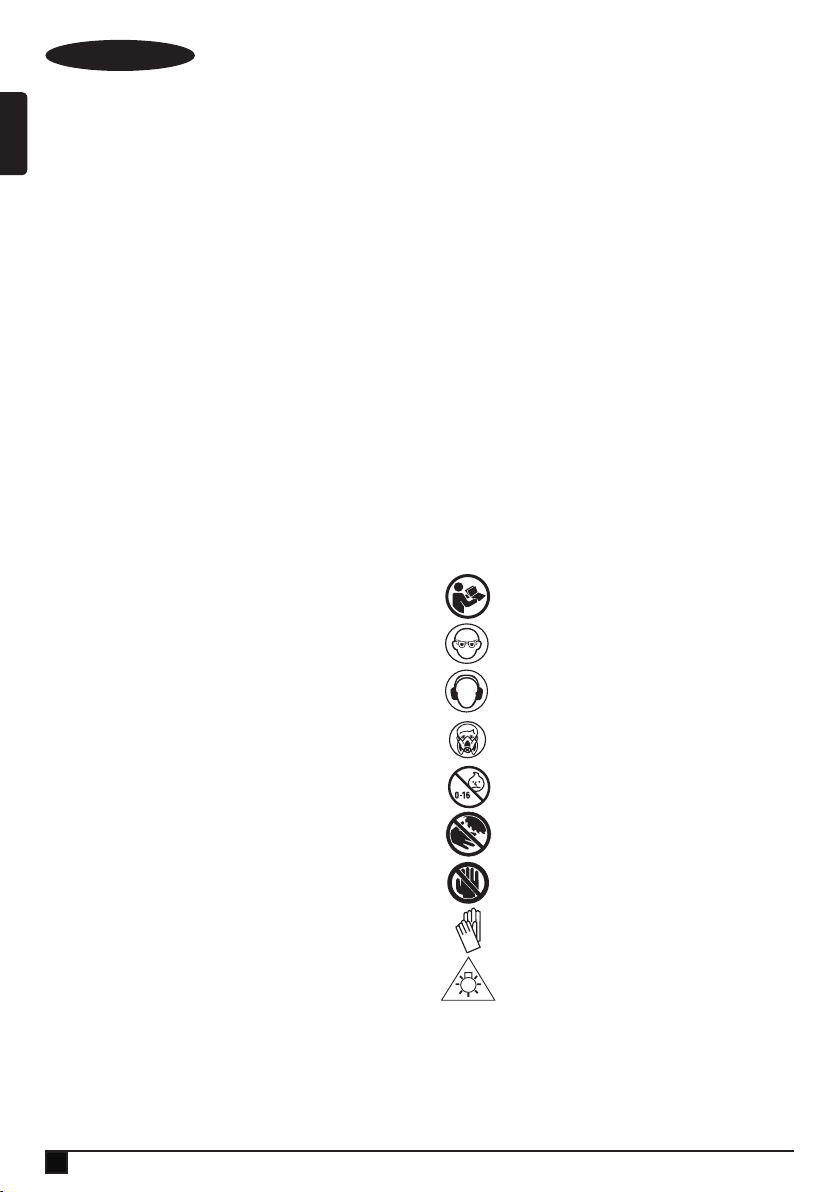
DEUTSCH
(Übersetzung der ursprünglichen Anweisungen)
u Diese Gehrungssäge wurde ausschließlich zum Sägen
von Holz, Kunststoff und Buntmetallen entwickelt.
Verwenden Sie das Gerät nicht zum Schneiden von
Werkstoffen, die nicht vom Hersteller empfohlen sind.
u Stehen Sie nie auf dem Elektrowerkzeug. Wenn das
Elektrowerkzeug kippt oder in Kontakt mit dem Sägeblatt
gerät, können schwere Verletzungen entstehen.
Warning! Beim Sägen von Kunststoffen,
@
Holz, das mit einer Beschichtung gegen das
Auslaufen von Panzensaft versehen ist, und
anderen Materialien kann sich geschmolzenes
Material auf den Spitzen und dem Körper des
Sägeblatts ansammeln, wodurch das Risiko des
Überhitzens und Blockierens des Sägeblatts
beim Schneiden erhöht wird.
Sicherheit anderer Personen
u Dieses Ladegerät darf von Kindern ab 8 Jahren und
Personen mit eingeschränkten körperlichen, sensorischen
oder geistigen Fähigkeiten sowie mangelnder Erfahrung
und Wissen in Bezug auf dessen Gebrauch bedient
werden, wenn sie bei der Verwendung des Geräts
beaufsichtigt oder angeleitet werden und die möglichen
Gefahren verstehen.
u Kinder dürfen nicht mit dem Gerät spielen. Reinigung und
Wartungsarbeiten dürfen von Kindern nur unter Aufsicht
durchgeführt werden.
Restrisiken
Folgende Risiken sind mit der Verwendung von Sägen
untrennbar verbunden:
Auch bei der Einhaltung der entsprechenden Sicherheitsvorschriften und der Verwendung aller Sicherheitsgeräte
bestehen weiterhin bestimmte Restrisiken. Diese sind:
u Verletzungen, die durch das Berühren von sich dre-
henden/bewegenden Teilen verursacht werden.
u Schwerhörigkeit.
u Unfallrisiko durch ungeschützte Teile des sich drehenden
Sägeblatts.
u Das Austauschen von Teilen, Messern oder Zubehör kann
Verletzungen zur Folge haben.
u Quetschen der Finger beim Öffnen der Schutzabdeckun-
gen.
u Gesundheitsrisiken durch das Einatmen von Staub beim
Sägen von Holz, insbesondere Eiche, Buche und Pressspan.
u Der längere Gebrauch eines Geräts kann Verletzungen
zur Folge haben. Legen Sie bei längerem Gebrauch
regelmäßige Pausen ein.
Lärm
Die angegebenen Werte der Lärmemissionen entsprechen
den Richtwerten einer genormten Prüfung und lassen sich
zum Vergleich verschiedener Geräte verwenden.
Außerdem kann mit Hilfe dieser Werte die Belastung bei Verwendung des Geräts schon im Voraus eingeschätzt werden.
Warnung! Die bei Verwendung des Geräts auftretenden
Lärmemissionen hängen von der Art des Gerätegebrauchs
und insbesondere von der Art der bearbeiteten Werkstücke ab
und können dementsprechend von den angegebenen Werten
abweichen.
Warnung! Tragen Sie immer geeigneten Gehörschutz.
Unter bestimmten Bedingungen und je nach Anwendungsdauer kann das Geräusch dieses Produktes zu Gehörverlust
führen. Beachten Sie die folgenden Faktoren, die sich auf die
Lärmexposition auswirken:
u Verwenden Sie Sägeblätter, die Lärmemissionen mindern,
u Verwenden Sie nur richtig geschärfte Sägeblätter, und
u Verwenden Sie speziell konstruierte, lärmreduzierende
Sägeblätter.
Etiketten am Werkzeug
Folgende Piktogramme sowie der Datumscode benden sich
auf dem Werkzeug:
Warnung! Lesen Sie vor Gebrauch die Anleitung. Andernfalls besteht Verletzungsgefahr.
Tragen Sie eine Schutzbrille.
Tragen Sie Gehörschutz.
Tragen Sie eine Staubmaske.
Das Gerät darf nicht von Personen unter 16
Jahren verwendet werden.
Halten Sie Ihre Hände nicht in die Nähe des
Sägeblatts.
Bereich “Keine Hände” – Halten Sie Finger und
Arme von den rotierenden Sägeblättern fern.
Tragen Sie beim Umgang mit den Sägeblättern
Handschuhe.
Starren Sie nicht auf die Betriebsleuchte.
Zusätzliche Sicherheitshinweise für Akkus und
Ladegeräte
Warnung! Das Gerät darf nur mit dem im Lieferumfang
enthaltenen Netzteil betrieben werden.
26
Page 27

(Übersetzung der ursprünglichen Anweisungen)
DEUTSCH
Hinweis: Der empfohlene Betriebstemperaturbereich des
Werkzeugs liegt zwischen 4 °C und 40 °C.
Akkus
u Keinesfalls versuchen, den Akku zu öffnen.
u Achten Sie darauf, dass der Akku nicht mit Wasser in
Berührung kommt.
u Nicht bei Temperaturen über 40 °C lagern.
u Laden Sie den Akku ausschließlich bei Umgebungstem-
peraturen zwischen 10 °C und 40 °C.
u Verwenden Sie ausschließlich das mitgelieferte Ladegerät.
u Beachten Sie bei der Entsorgung von Batterien und Akkus
die Hinweise im Abschnitt “Umweltschutz”.
Versuchen Sie nie, beschädigte Akkus aufzuladen.
p
Ladegeräte
u Verwenden Sie das Stanley FatMax Ladegerät nur für den
Akku des Werkzeugs, mit dem es geliefert wurde. Andere
Akkus können platzen und Sachschäden oder Verletzungen verursachen.
u Versuchen Sie keinesfalls, nicht auadbare Batterien zu
laden.
u Lassen Sie beschädigte Kabel sofort austauschen.
u Achten Sie darauf, dass das Ladegerät nicht mit Wasser
in Berührung kommt.
u Versuchen Sie nicht, das Ladegerät zu öffnen.
u Nehmen Sie am Ladegerät keine Veränderungen vor.
Das Ladegerät darf nur im Innenbereich
$
+
verwendet werden.
Vor Gebrauch die Anleitung lesen.
Elektrische Sicherheit
Das Ladegerät ist schutzisoliert, daher ist
keine Erdleitung erforderlich. Stellen Sie
#
sicher, dass die Netzspannung der auf dem
Typenschild des Geräts angegebenen Spannung entspricht. Ersetzen Sie das Ladegerät
keinesfalls durch ein normales Netzkabel.
u Ist das Netzkabel beschädigt, muss es durch den
Hersteller oder eine Stanley FatMax Vertragswerkstatt
ausgetauscht werden, um eine mögliche Gefährdung zu
vermeiden.
Merkmale
Dieses Gerät verfügt über einige oder alle der folgenden
Merkmale:
1. Auslöseschalter
2. Bediengriff
3. Montagebohrungen
4. Untere Schutzvorrichtung
5. Gehrungsverriegelung
6. Gehrungsriegeltaste
7. Schlitzplatte
8. Gehrungsskala
9. Gehrungsskalenanzeige
10. Tragegriffe
11. Anschlag
12. Neigungsverriegelungsknopf
13. Schienen
13a. Klettband
14. Staubabsauganschluss
15. Akku
16. Arbeitsleuchtenschalter
17. Arretierhebel
18. Schienenverriegelungsschraube
19. Klemmenbefestigungsbohrung
20. Arretierstift
Montage (Abb. A)
Ihre Gehrungssäge wird teilweise zusammengebaut geliefert.
uÖffnen Sie die Verpackung und heben Sie die Säge an
den Tragegriffen (10) im Unterteil der Säge heraus (Abb.
A).
u Stellen Sie die Säge auf eine glatte, ache Oberäche wie
eine Werkbank oder einen stabilen Tisch.
u Beachten Sie das Montagediagramm auf Seite 2 dieses
Handbuchs, um sich mit der Säge und ihren veschiedenen
Teilen vertraut zu machen. Der Abschnitt über Einstellungen bezieht sich auf die Begriffe darin, daher sollten Sie
wissen, was und wo die Teile sind.
u Die Gehrungsverriegelung (5) ist beim Versand nicht
montiert. Nehmen Sie die Gehrungsverriegelung (5) aus
der Verpackung und schrauben Sie sie an die Säge; die
richtige Stelle zeigen die Abbildungen G und J.
u Ihre Säge besitzt einen integrierten Staubabsaugaschluss
(14), der es ermöglicht, entweder den mitgelieferten, aber
nicht montierten Staubbeutel (35) oder ein Staubabsaugsystem der Werkstatt anzuschließen (Abb. M).
Schlitzplatte (Abb. J)
Die Schlitzplatte (7) wird mit 6 Schrauben am Tisch befestigt.
Die Schlitzplatte (7) ist nicht höhenverstellbar.
Hinweis: Wenn die Schlitzplatte (7) abgenutzt oder beschädigt ist oder ausgetauscht werden muss, sollten Reparaturen
durch eine Vertragswerkstatt oder durch den Stanley Fat Max
Kundendienst erfolgen.
Arretierstift (Abb. F)
Warnung! Der Arretierstift darf NUR beim Transportieren und
Aufbewahren der Säge eingesetzt werden. Verwenden Sie
den Arretierstift NIEMALS bei Schneidevorgängen.
27
Page 28
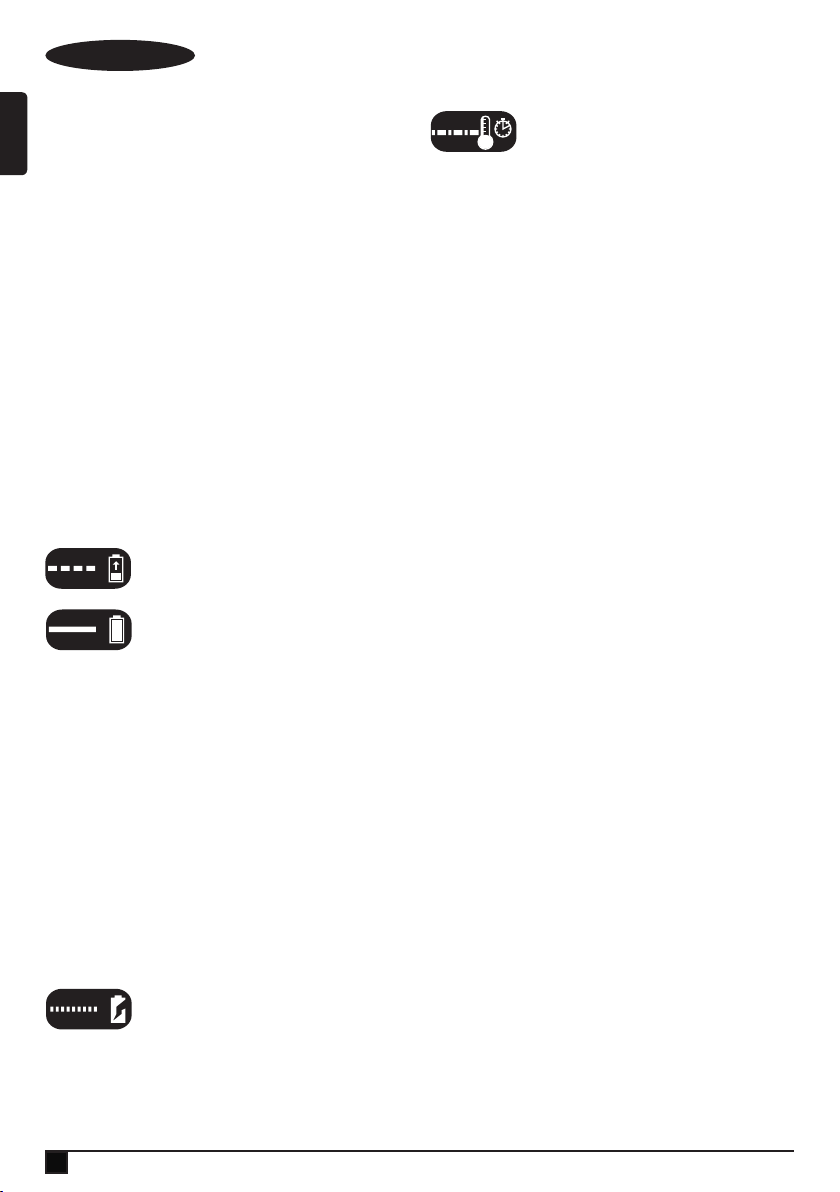
DEUTSCH
(Übersetzung der ursprünglichen Anweisungen)
Hinweis: Zum Anheben, Tragen und Abstützen der
Gehrungssäge während des Transports sind die beiden
Tragegriffe (10) auf beiden Seiten des Unterteils der
Gehrungssäge zu verwenden (Abb. A).
Zum Sperren des Sägekopfes in der unteren Position schieben Sie den Sägekopf nach unten, drücken den Arretierstift
(20) herein und lassen den Sägekopf los. Dadurch wird der
Sägekopf sicher nach unten gehalten, um die Säge zu
transportieren. Zum Lösen drücken Sie den Sägekopf nach
unten und ziehen den Stift heraus.
Warnung! Vergewissern Sie sich immer, dass das Werkzeug
ausgeschaltet ist und der Akku herausgenommen wurde,
bevor Sie die Werkzeugfunktion einstellen oder überprüfen.
Laden eines Akkus (Abb. B)
Stanley FatMax-Ladegeräte sind zum Auaden von Stanley
FatMax-Akkus vorgesehen.
u Setzen Sie das Ladegerät (21) in eine geeignete Steck-
dose ein, bevor Sie einen Akku (15) einsetzen.
u Legen Sie den Akku (15) vollständig in das Ladegerät ein,
achten Sie dabei darauf, dass er vollständig eingesetzt ist
(Abbildung B).
Die LED (21a) blinkt, wenn der Akku geladen
wird.
Der Abschluss des Ladevorgangs wird
dadurch angezeigt, dass die LED dauerhaft
leuchtet. Der Akku ist vollständig aufgeladen
und kann jetzt verwendet oder in der Ladestation gelassen
werden.
u Laden Sie entladene Akkus so bald wie möglich nach dem
Gebrauch wieder auf, da sonst die Batterielebensdauer
stark verringert werden kann.
u Um die maximal Akkulaufzeit zu erreichen, sollte der Akku
nicht vollständig entladen werden. Es wird empfohlen, den
Akku nach jedem Gebrauch aufzuladen.
Ladegerätdiagnose (Abb. C)
Dieses Ladegerät wurde entwickelt, um bestimmte Probleme
zu erkennen, die im Zusammenhang mit den Akkus oder der
Stromquelle entstehen können. Probleme werden dadurch
angezeigt, dass eine LED in verschiedenen Sequenzen blinkt.
Defekter Akku
Das Ladegerät kann einen schwachen oder
beschädigten Akku erkennen. Die LED
blinkt mit dem Muster, das auf dem Etikett
angegeben ist. Wenn das Blinkmuster für einen defekten Akku
zu sehen ist, laden Sie den Akku nicht weiter auf. Bringen Sie
ihn zu einem Kundendienstzentrum oder einer RecyclingSammelstelle.
28
Verzögerung heißer/kalter Akku
Wenn das Ladegerät erkennt, dass ein
Akku übermäßig heiß oder kalt ist, startet es
automatisch eine “Verzögerung heißer/kalter
Akku”, bis sich der Akku normalisiert hat. Danach schaltet
das Ladegerät automatisch in den Akku-Lademodus. Diese
Funktion gewährleistet eine maximale Lebensdauer des
Akkus. Die Leuchte blinkt mit dem Muster, das auf dem Etikett
angegeben ist.
Belassen des Akkus im Ladegerät
Sie können den Akku auf unbestimmte Zeit im Ladegerät
belassen. In diesem Fall leuchtet die LED-Anzeige dauerhaft.
Das Ladegerät hält den Akku immer einsatzbereit und vollständig aufgeladen.
Dieses Ladegerät verfügt über einen automatischen
Feinabstimmungsmodus, der die einzelnen Zellen im Akku
abgleicht oder ausgleicht, um eine maximale Kapazität zu
gewährleisten.
Die Feinabstimmung des Akkus sollte wöchentlich erfolgen
oder wenn der Akku keine ausreichende Leistung mehr liefert.
Um die automatische Feinabstimmung zu verwenden, setzen
Sie den Akku in das Ladegerät ein und lassen ihn mindestens
8 Stunden darin stecken.
Wichtige Hinweise zum Auaden
u Die längste Lebensdauer und die beste Leistung werden
erhalten, wenn der Akku dann geladen wird, wenn die
Lufttemperatur zwischen 18 °C – 24 °C liegt. Laden Sie
den Akku NICHT bei einer Lufttemperatur unter +4,5
°C oder über +40 °C. Dies ist wichtig, da so schwere
Schäden am Akku verhindert werden.
u Das Ladegerät und der Akku können sich während des
Ladevorgangs warm anfühlen. Das ist normal und
deutet nicht auf ein Problem hin.
u Um das Abkühlen des Akkus nach dem Gebrauch zu er-
leichtern, platzieren Sie das Ladegerät und den Akku nicht
in einer warmen Umgebung, wie beispielsweise in einem
Metallschuppen oder einem nicht isolierten Wohnwagen.
u Wenn der Akku nicht richtig aufgeladen wird:
u Prüfen Sie die Funktionsfähigkeit der Steckdose, indem
Sie eine Lampe oder ein anderes Gerät daran
anschließen;
u Überprüfen Sie, ob die Steckdose mit einem
Lichtschalter verbunden ist, der auch das Gerät
ausschaltet, wenn das Licht ausgeschaltet wird;
u Bringen Sie Ladegerät und Akku an einen Ort, dessen
Umgebungstemperatur etwa 18 °C – 24 °C beträgt;
u Wenn die Probleme beim Auaden weiterhin bestehen,
bringen Sie das Werkzeug, den Akku und das
Ladegerät zu Ihrem Kundendienstzentrum.
u Der Akku sollte aufgeladen werden, wenn er nicht mehr
genügend Leistung für Aufgaben erbringt, die zuvor
Page 29

(Übersetzung der ursprünglichen Anweisungen)
DEUTSCH
einfach erledigt wurden. Betreiben Sie das Werkzeug in
diesem Fall NICHT WEITER. Befolgen Sie die Anweisun-
gen bezüglich des Auadens. Sie können auch jederzeit
einen teilweise entleerten Akku auaden, ohne dass dies
nachteilige Auswirkungen auf den Akku hat.
u Leitende Fremdmaterialien, unter anderem Schleifstaub,
Metallspäne, Stahlwolle, Aluminiumfolie oder
Anhäufungen von Metallpartikeln, sollte von Hohlräumen
des Ladegeräts ferngehalten werden. Ziehen Sie den
Netzstecker des Ladegerätes vor dem Reinigen aus der
Steckdose.
u Das Ladegerät nicht einfrieren oder in Wasser oder
andere Flüssigkeiten tauchen.
Einsetzen und Entfernen des Akkus (Abb. D, E)
u Um den Akku (15) einzusetzen, richten Sie ihn an der
Aufnahme am Gerät (22) aus. Schieben Sie den Akku in
die Aufnahme, bis er in der richtigen Position einrastet.
u Um den Akku zu entfernen, drücken Sie die Akku-
Entriegelungstaste (15a) und ziehen Sie gleichzeitig den
Akku aus der Aufnahme, siehe Abbildung E.
Wechsel oder Montage eines neuen Sägeblatts
(Abb. G, H, I)
Warnung! Um die Gefahr schwerer Verletzungen zu mindern,
schalten Sie das Werkzeug aus und entfernen Sie den Akku,
bevor Sie es transportieren, Einstellungen vornehmen oder
Anbaugeräte oder Zubehör anbringen oder entfernen. Ungewolltes Anlaufen kann Verletzungen verursachen.
Entfernen des Sägeblatts
u Entfernen Sie den Akku (15) aus der Säge.
u Heben Sie den Arm in die obere Position und den unteren
Blattschutz (4) so weit wie möglich.
u Entfernen Sie die vordere Schraube der Schutzklammer
(24) nicht, aber lösen Sie sie so weit, bis die Klammer (25)
weit genug angehoben werden kann, um an die
Sägeblattschraube (26) zu gelangen. Die untere
Schutzvorrichtung bleibt dann aufgrund der Position der
Schraube der Schutzklammer angehoben.
u Drücken Sie den Spindelarretierungsknopf (28) und
drehen Sie das Sägeblatt (29) vorsichtig von Hand, bis die
Arretierung einrastet.
u Halten Sie den Knopf gedrückt und lösen Sie mit der
anderen Hand und der Sechskantseite des mitgelieferten
Schlüssels die Sägeblattschraube (26). (Im Uhrzeigersinn
drehen, Linksgewinde.)
u Entfernen Sie die Sägeblattschraube (26) mit der
Sechskantseite des mitgelieferten Schlüssels, ebenso
die Unterlegscheibe der äußeren Schraubklemme (30)
und das Sägeblatt (29). Die innere Unterlegscheibe der
Schraubklemme (31) kann auf der Spindel (32) bleiben.
Anbringen eines Sägeblatts
u Entfernen Sie den Akku (15) aus der Säge.
u Halten Sie den Arm angehoben, die untere Schutzvorrich-
tung (4) geöffnet und die Schutzklammer (25) angehoben
und setzen Sie das Sägeblatt (29) auf die Spindel (32)
und so gegen die innere Sägeblattklemme (31), dass die
Zähne des Sägeblatts in die auf der Säge angegebene
Drehrichtung zeigen.
u Montieren Sie die Unterlegscheibe der äußeren Schraub-
klemme (30) auf die Spindel (32).
u Montieren Sie die Sägeblattschraube (26) und, während
Sie die Spindelarretierung (28) betätigen, ziehen Sie
die Schraube (26) mit dem mitgelieferten Schlüssel fest
(gegen den Uhrzeigersinn drehen, Linksgewinde).
u Bringen Sie die Schutzklammer (25) in ihre ursprüngliche,
vollständig nach unten geführte Position zurück und
ziehen Sie die Schraube der Schutzklammer (24) fest, um
die Klammer dort zu befestigen.
Schnittlinienführungssystem
Warnung! Blicken Sie nicht in die Arbeitsleuchte. Dies könnte
zu schweren Augenverletzungen führen.
Hinweis: Der Akku muss aufgeladen und mit der
Gehrungssäge verbunden sein.
Das Schnittlinienführungssystem kann nur über den Arbeitsleuchtenschalter (16) ein- oder ausgeschaltet werden.
So schneiden Sie entlang einer vorgezeichneten Linie auf
einem Holzstück: Schalten Sie das Schnittlinienführungssystem über den Arbeitsleuchtenschalter (16) ein (nicht über den
Hauptschalter) und ziehen Sie dann den Bediengriff (2) nach
unten, um das Sägeblatt nahe an das Holz zu bringen.
Der Schatten des Sägeblatts erscheint auf dem Holz. Diese
Schattenlinie repräsentiert das Material, das vom Sägeblatt
beim Sägen entfernt wird.
Um den Schnitt korrekt an der Bleistiftlinie zu positionieren,
richten Sie die Bleistiftlinie an der Kante des
Sägeblattschattens aus. Denken Sie daran, den Gehrungsoder Neigungswinkel anzupassen, damit er der Linie genau
entspricht.
Ihre Säge ist mit einer Akkufehlerfunktion ausgestattet. Die
Arbeitsleuchte beginnt zu blinken, wenn der Akku nicht
mehr genügend aufgeladen ist, um die nötige Leistung zu
erbringen, oder wenn der Akku zu heiß ist. Laden Sie den
Akku auf, bevor Sie mit dem Sägen fortfahren. Beachten Sie
zum Auaden von Akkus die Hinweise zum Ladevorgang im
Abschnitt „Wichtige Sicherheitshinweise für Akkus“.
Gehrungssteuerung (Abb. J)
Mit der Gehrungsverriegelung (5) und der Gehrungsriegeltaste (6) können Sie die Säge auf Winkel von 47° nach rechts
und 47° nach links gehren. Die Gehrungsarretierung rastet
sowohl links als auch rechts automatisch bei 0˚, 15˚, 22,5˚,
29
Page 30

DEUTSCH
(Übersetzung der ursprünglichen Anweisungen)
31,6˚ und 45˚ ein. Um die Säge zu gehren, entriegeln Sie die
Gehrungsarretierung, indem Sie die Gehrungsverriegelung (5)
zum Entriegeln gegen den Uhrzeigersinn und zum Sperren im
Uhrzeigersinn drehen. Ziehen Sie die Gehrungsriegeltaste (6)
nach oben und stellen Sie den gewünschten Gehrungswinkel
auf der Gehrungsskala (8) ein. Sperren Sie die Gehrungsverriegelung (5) durch Drehen im Uhrzeigersinn.
Neigungsverriegelungsknopf (Abb. K)
Mit der Neigungsverriegelung kann die Säge um 48°
nach links geneigt werden. Drehen Sie zum Einstellen der
Neigung den Neigungsverriegelungsknopf (12) gegen den
Uhrzeigersinn, um ihn zu lockern. Drehen Sie den Neigungsverriegelungsknopf zum Festziehen im Uhrzeigersinn.
Achtung! Quetschgefahr. Achten Sie darauf, den Neigungsverriegelungsknopf festzuziehen, bevor Sie Umgehungen
einstellen.
Auslöseschalter (Abb. L)
Um die Säge einzuschalten, drücken Sie den Arretierhebel
(17) nach links, drücken Sie dann den Auslöser (1) herein.
Die Säge läuft, solange der Schalter eingedrückt wird. Lassen
Sie das Sägeblatt vor dem Sägen bis zur Arbeitsgeschwindigkeit hochdrehen. Um die Säge auszuschalten, lassen Sie
den Schalter los. Lassen Sie das Sägeblatt erst anhalten,
bevor Sie den Sägekopf anheben. Es ist keine Vorrichtung
vorhanden, um den Schalter in der eingeschalteten Position
zu sperren. Ein Loch (1a) im Auslöser ist dafür vorgesehen,
ein Vorhängeschloss einzusetzen, um den Schalter zu sperren.
Ihre Säge ist nicht mit einer automatischen elektrischen Sägeblattbremse ausgestattet, aber das Sägeblatt sollte innerhalb
von 5 Sekunden stoppen, nachdem der Auslöser losgelassen
wird. Dieses Merkmal ist nicht einstellbar. Wenn die Stoppzeit
wiederholt länger als 5 Sekunden ist, lassen Sie das
Werkzeug von einer Stanley FatMax-Vertragswerkstatt
warten.
Vergewissern Sie sich immer, dass das Sägeblatt angehalten
hat, bevor Sie es aus dem Schnitt nehmen.
Staubabsaugung (Abb. M)
Warnung! Um die Gefahr schwerer Verletzungen zu mindern,
schalten Sie das Werkzeug aus und entfernen Sie den Akku,
bevor Sie es transportieren, Einstellungen vornehmen oder
Anbaugeräte oder Zubehör anbringen oder entfernen.
Ungewolltes Anlaufen kann Verletzungen verursachen.
Ihre Säge besitzt einen integrierten Staubabsauganschluss
(14), der es ermöglicht, entweder den mitgelieferten
Staubbeutel (35) oder ein Staubabsaugsystem der Werkstatt
anzuschließen.
Anbringen des Staubbeutels
u Befestigen Sie den Staubbeutel (35) wie in Abbildung M
gezeigt am Staubabsauganschluss (14).
30
u Anstelle des Staubbeutels (35) kann am Staubabsau-
ganschluss (14) auch ein Staubsaugerschlauch (38
- nicht mitgeliefert) angebracht werden. Dazu wird der
Staubsaugerschlauch (38) anstelle des Staubbeutels (35)
montiert, siehe Abbildung M.
u Verwenden Sie das Klettband (13a), um den Staubsauger-
schlauch (38) während des Betriebs der Säge von den
Gleitschienen (13) fernzuhalten.
Hinweis: Das Klettband (13a) eignet sich nicht als Tragegriff
und sollte nicht zum Bewegen oder Transportieren der Säge
verwendet werden.
Leeren des Staubbeutels
uNehmen Sie den Staubbeutel (35) von der Säge und
schütteln oder klopfen Sie ihn vorsichtig aus.
u Bringen Sie den Staubbeutel wieder am Staubabsaugan-
schluss (14) an.
Eventuell löst sich nicht der gesamte Staub aus dem Beutel.
Dies wirkt sich nicht auf die Sägeleistung aus, reduziert aber
die Staubsammelefzienz der Säge. Um die Staubsammelefzienz der Säge wiederherzustellen, drücken Sie beim Leeren
des Staubbeutels auf die Feder im Inneren und klopfen Sie
ihn gegen den Rand der Mülltonne.
Warnung! Betreiben Sie diese Säge nur, wenn der Staubbeutel angebracht ist. Holzstaub kann Atemprobleme
verursachen.
Der Sägevorgang
Wenn die Schiebefunktion nicht verwendet wird, stellen Sie
sicher, dass der Sägekopf soweit wie möglich zurückgeschoben und die Schienenverriegelungsschraube (18) festgezogen
ist. Das verhindert, dass die Säge sich auf den Schienen
verschiebt, wenn das Werkstück aufgelegt wird.
Hinweis: SCHNEIDEN SIE MIT DIESER SÄGE KEINE
EISENHALTIGEN METALLE ODER MAUERWERK.
NICHTEISENMETALLE DÜRFEN MIT DIESER SÄGE
GESCHNITTEN WERDEN. Verwenden Sie keine Schleif-
scheiben.
Hinweis: Beachten Sie vor dem Sägen die Hinweise zur Betätigung und Sichtbarkeit der Schutzvorrichtung im Abschnitt
„Einstellungen“, der wichtige Informationen über die untere
Schutzvorrichtung enthält.
Querschnitte (Abb. N)
Ein Querschnitt ist ein Schnitt durch Holz in einem beliebigen
Winkel quer zur Maserung. Ein gerader Querschnitt erfolgt
mit dem Gehrungsarm in der Null-Grad-Position. Stellen Sie
den Gehrungsarm bei null ein und verriegeln Sie ihn, und
halten Sie das Holz fest gegen den Tisch und den Anschlag.
Schalten Sie bei festgezogener Schienenverriegelungsschraube (18) die Säge ein, indem Sie den Auslöseschalter (1)
hereindrücken.
Page 31

(Übersetzung der ursprünglichen Anweisungen)
DEUTSCH
Wenn die Säge schneller wird (nach etwa 1 Sekunde),
senken Sie den Arm gleichmäßig und langsam ab, um das
Holz zu schneiden. Lassen Sie das Sägeblatt vollständig zum
Stillstand kommen, bevor Sie den Arm heben.
Wenn Werkstücke geschnitten werden, die größer als 2 x 4
(51 x 102) sind, führen Sie mit gelöster Schienenverriegelungsschraube (18) eine Bewegung nach außen-unten-zurück
durch. Ziehen Sie die Säge heraus, zu Ihnen hin, senken
Sie den Sägekopf nach unten zum Werkstück hin ab, und
schieben Sie die Säge langsam zurück, um den Schnitt zu
vervollständigen. Lassen Sie das Sägeblatt beim Herausziehen nicht die Oberseite des Werkstücks berühren. Die Säge
könnte sich auf Sie zu bewegen und Verletzungen oder
Schäden am Werkstück verursachen.
Warnung! Verwenden Sie immer einen Schraubstock, um
die Kontrolle zu behalten und um das Risiko zu reduzieren,
dass das Werkstück beschädigt wird und es zu Verletzungen
kommt, wenn sich Ihre Hände innerhalb von 6” (152 mm) vom
Sägeblatt benden müssen, während Sie sägen.
Hinweis! Die Schienenverriegelungsschraube (18) muss
locker sein, damit die Säge an den Schienen entlanggleiten
kann.
Gehrungsquerschnitte erfolgen mit dem Gehrungsarm in
einem anderen Winkel als Null.
Dieser Winkel ist häug 45º für Ecken, kann aber auf jeden
Wert von Null bis 47º links oder 47° rechts eingestellt werden.
Gehen Sie beim Sägen wie oben beschrieben vor.
Bei einem Gehrungsschnitt an Werkstücken, die breiter als 2
x 6 Zoll aber kürzer sind, setzen Sie die längere Seite gegen
den Anschlag (Abb. N).
Um entlang einer vorgezeichneten Linie auf einem Holzstück
zu schneiden, muss der Winkel so weit wie möglich damit
übereinstimmen. Schneiden Sie das Holz etwas zu lang ab
und messen Sie von der Bleistiftlinie bis zur Schnittkante,
um zu bestimmen, in welche Richtung der Gehrungswinkel
eingestellt und neu gesägt werden muss. Dies erfordert einige
Übung, ist aber eine häug verwendete Technik.
Sägeblattschärfe und Schnittgeschwindigkeit beeinussen die
Schnittqualität. Wenn besonders glatte Schnitte für Präzisionsarbeiten benötigt werden, erzeugen ein scharfes (60-zahnige
Hartmetallspitzen) Sägeblatt und eine langsamere,
gleichmäßige Schnittgeschwindigkeit die gewünschten Ergebnisse. Stellen Sie sicher, dass sich das Material beim Sägen
nicht bewegen oder wandern kann; spannen Sie es daher
gut fest. Lassen Sie das Sägeblatt vollständig zum Stillstand
kommen, bevor Sie den Arm heben.
Wenn am hinteren Ende des Werkstücks noch kleine Fasern
oder Holzstücke herausbrechen, kleben Sie Abdeckband auf
die Stelle am Holz, wo der Schnitt vorgenommen werden soll.
Sägen Sie durch das Band und entfernen Sie es nach dem
Sägen sorgfältig.
Beachten Sie für verschiedene Schneidanwendungen die
Liste der empfohlenen Sägeblätter für Ihre Säge und wählen
Sie diejenige aus, die Ihren Anforderungen am besten entspricht. Siehe „Sägeblätter“ unter „Optionales Zubehör“.
Korrekte Körper- und Handhaltung (Abb. O1–O4)
Die richtige Positionierung von Körper und Händen beim Betrieb der Gehrungssäge macht das Sägen einfacher, genauer
und sicherer. Halten Sie Ihre Hände vom Schneidbereich fern.
Platzieren Sie die Hände nicht näher als 6“ (152 mm) von der
Klinge entfernt. Halten Sie das Werkstück beim Sägen dicht
am Tisch und Anschlag. Halten Sie Ihre Hände in der Position,
bis der Schalter losgelassen wurde und das Sägeblatt
vollständig zum Stillstand gekommen ist.
MACHEN SIE IMMER EINEN VERSUCH (MIT AUSGESCHALTETER SÄGE), BEVOR SIE MIT DEM EINGESCHALTETEN GERÄT ARBEITEN, SO DASS SIE DIE
BAHN DES SÄGEBLATTS ÜBERPRÜFEN KÖNNEN.
KREUZEN SIE IHRE HÄNDE NICHT, SIEHE ABB. O3.
Halten Sie beide Füße fest auf dem Boden und achten Sie
darauf, das Gleichgewicht zu behalten. Folgen Sie den
Bewegungen des Sägearms nach links und rechts. Stehen
Sie dabei ein wenig seitlich des Sägeblattes. Sehen Sie durch
das Schutzgitter, wenn Sie einer vorgezeichneten Schnittlinie
folgen.
Neigungsschnitte
Ein Neigungsschnitt ist ein Querschnitt, bei dem das Sägeblatt
schräg zum Holz geneigt ist. Um die Abschrägung einzustellen, lockern Sie den Neigungsverriegelungsknopf (12) und
bewegen Sie die Säge wie gewünscht nach links. Sobald der
gewünschte Neigungswinkel eingestellt ist, ziehen Sie die
Neigungsverriegelung fest an. Neigungswinkel können von 3°
nach rechts bis 48° nach links eingestellt werden.
Schnittqualität
Die Glätte jedes Schnitts hängt von mehreren Variablen
ab. Faktoren wie das zu sägende Material, Sägeblatttyp,
Einspannen des Werkstücks
Warnung! Um die Gefahr schwerer Verletzungen zu mindern,
schalten Sie das Werkzeug aus und entfernen Sie den Akku,
bevor Sie es transportieren, Einstellungen vornehmen oder
Anbaugeräte oder Zubehör anbringen oder entfernen. Ungewolltes Anlaufen kann Verletzungen verursachen.
Warnung! Ein eingespanntes Werkstück, das vor einem
Schnitt symmetrisch und sicher war, kann danach unsymmetrisch sein. Bei unausgeglichener Last kann die Säge
kippen oder andere Objekte, an der die Säge befestigt ist,
z.B. ein Tisch oder eine Werkbank, können kippen. Bei einem
Schnitt, der evtl. unsymmetrisch wird, muss das Werkstück
31
Page 32

DEUTSCH
(Übersetzung der ursprünglichen Anweisungen)
korrekt abgestützt werden, stellen Sie dabei sicher, dass die
Säge fest auf einer stabilen Fläche befestigt ist. Dies könnte
zu Verletzungen führen.
Warnung! Der Fuß der Schraubklemme muss immer über
dem Unterteil der Säge festgeklemmt werden, wenn die
Schraubklemme verwendet wird. Klemmen Sie das Werkstück
immer am Unterteil der Säge fest – und nirgendwo sonst am
Arbeitsbereich. Stellen Sie sicher, dass der Fuß der Schraubklemme nicht am Rand des Unterteils der Säge festgeklemmt
wird.
Warnung! Verwenden Sie immer einen Schraubstock, um
die Kontrolle zu behalten und um das Risiko zu reduzieren,
dass das Werkstück beschädigt wird und es zu Verletzungen
kommt, wenn sich Ihre Hände innerhalb von 6” (152 mm)
vom Sägeblatt benden müssen, während Sie sägen. Wenn
Sie das Werkstück nicht mit der Hand auf dem Tisch und
gegen den Anschlag sichern können (unregelmäßige Form
usw.) oder Ihre Hand weniger als 6“ (152 mm) vom Sägeblatt
entfernt gehalten werden muss, muss eine Klemme oder eine
andere Haltevorrichtung verwendet werden.
Verwenden Sie den Schraubstock, der mit Ihrer Säge geliefert
wird. Einen Schraubstock erhalten Sie auch bei Ihrem Händler
oder beim Stanley Fat Max-Kundendienst.
Andere Hilfen wie Federklammern oder Schraubzwingen können für bestimmte Größen und Materialformen geeignet sein.
Seien Sie bei der Auswahl und Platzierung dieser Vorrichtungen vorsichtig. Nehmen Sie sich Zeit für einen Trockenlauf,
bevor Sie mit dem Sägen beginnen.
Anbringen des Schraubstocks (Abb. P)
u Stecken Sie den Schraubstock (37) in das Loch (19) hinter
dem Anschlag. Der Schraubstock sollte in Richtung der
Rückseite der Gehrungssäge zeigen. Die Rille an der
Stange des Schraubstocks sollte vollständig im Unterteil
sitzen. Stellen Sie sicher, dass die Rille vollständig in das
Unterteil der Gehrungssäge eingesetzt ist. Wenn die Rille
sichtbar ist, ist der Schraubstock nicht sicher.
u Drehen Sie den Schraubstock um 180º zur Vorderseite
der Gehrungssäge.
u Lockern Sie den Knopf, um den Schraubstock nach oben
oder unten zu justieren, klemmen Sie dann das Werkstück
mit Hilfe des Feineinstellungsknopfes gut fest.
Hinweis: Setzen Sie den Schraubstock auf die gegenüberliegende Seite des Unterteils, wenn Sie Neigungsschnitte
vornehmen. MACHEN SIE IMMER EINEN VERSUCH (MIT
AUSGESCHALTETER SÄGE), BEVOR SIE MIT DEM EINGESCHALTETEN GERÄT ARBEITEN, SO DASS SIE DIE BAHN
DES SÄGEBLATTS ÜBERPRÜFEN KÖNNEN. STELLEN
SIE SICHER DASS DER SCHRAUBSTOCK NICHT DEN
BETRIEB DER SÄGE ODER DIE SCHUTZVORRICHTUNGEN BEHINDERT.
32
Einstellungen
Ihre Gehrungssäge wurde werksseitig genau eingestellt. Sollte
wegen des Transports oder aus irgendeinem anderen Grund
eine erneute Einstellung erforderlich sein, gehen Sie gemäß
den folgenden Schritten vor, um Ihre Säge einzustellen.
Die Einstellungen sollten dann zuverlässig bestehen bleiben.
Nehmen Sie sich jetzt etwas Zeit, um diese Anweisungen
genau zu befolgen, um die Präzision zu erhalten, zu der Ihre
Säge fähig ist.
Einstellung der Gehrungsskala (Abb. Q1)
Verriegeln Sie den Arm in der unteren Position. Entriegeln
Sie die Gehrungsverriegelung (5) und schwenken Sie
den Gehrungsarm, bis die Gehrungsriegeltaste (6) an der
Gehrungsposition 0° einrastet. Verriegeln Sie nicht die
Gehrungsverriegelung. Legen Sie ein Winkelmaß wie abgebildet gegen den Sägeanschlag und das Sägeblatt. (Berühren
Sie die Spitzen der Sägeblattzähne nicht mit dem Winkelmaß.
Dies kann zu ungenauen Messungen führen.)
Wenn das Sägeblatt nicht genau senkrecht zum Anschlag
steht, lockern und bewegen Sie den Materialanschlag, bis
das Sägeblatt senkrecht zum Anschlag steht; verwenden Sie
zum Messen ein Winkelmaß. Achten Sie dabei nicht auf die
Angaben auf dem Gehrungszeiger.
Einstellung des Winkelmaßes auf den Tisch (Abb.
Q2)
Zum Ausrichten des Winkelmaßes auf den Tisch, verriegeln
Sie den Arm mit dem Arretierstift (20) in der unteren Position.
Setzen Sie ein Winkelmaß gegen das Sägeblatt, stellen Sie
dabei sicher, dass das Winkelmaß nicht auf einem Zahn sitzt.
Lösen Sie den Neigungsverriegelungsknopf (5) und stellen
Sie sicher, dass der Arm fest gegen den 0° Neigungsanschlag
sitzt. Drehen Sie die 0° Neigungseinstellschraube (a5) mit
dem 1/2” (12,7 mm) Sägeblattschlüssel so weit, dass das
Sägeblatt eine 0° Neigung zum Tisch hat, so wie es mit dem
Winkelmaß gemessen wurde.
Betätigung und Sichtbarkeit der Schutzvorrichtung
(Abb. V)
Warnung! Quetschgefahr. Um das Verletzungsrisiko zu ver-
ringern, halten Sie den Daumen unter dem Bediengriff, wenn
Sie den Griff nach unten ziehen. Die untere Schutzvorrichtung
bewegt sich nach oben, wenn der Bediengriff nach unten
gezogen wird, was zu einem Einklemmen führen kann.
Die untere Schutzvorrichtung (4) an Ihrer Säge wird automa-
tisch hochgezogen, wenn der Arm gesenkt wird; er schwenkt
wieder zurück, wenn die Säge wieder in die obere Position
zurückkehrt.
Vor jedem Gebrauch oder nach den Einstellungen den Arm
(nicht mit Strom versorgt) vollständig drehen und sicherstellen, dass sich die Schutzvorrichtung problemlos öffnet und
vollständig schließt. Sie sollte das Sägeblatt nicht berühren.
Page 33

(Übersetzung der ursprünglichen Anweisungen)
DEUTSCH
Mit angehobenem Arm die Schutzvorrichtung (nicht mit Strom
versorgt) wie in Abbildung V gezeigt anheben. Die Schutzvorrichtung sollte sich schnell vollständig schließen.
Betreiben Sie die Säge nicht, falls sich die Schutzvorrichtung nicht ungehindert bewegt und nicht schnell vollständig
schließt. Klemmen der binden Sie die Schutzvorrichtung
niemals in einer offenen Position fest, wenn Sie die Säge
betreiben.
Der Blattschutz kann von Hand hochgezogen werden, wenn
Sägeblätter ausgewechselt werden und wenn der Zustand der
Säge geprüft werden soll.
HEBEN SIE NIEMALS DIE UNTERE SCHUTZVORRICHTUNG MIT DER HAND AN, WENN DAS SÄGEBLATT NOCH
LÄUFT.
Hinweis: Bestimmte Spezialschnitte in großem Material
erfordern, dass Sie die Schutzvorrichtung manuell anheben.
Beachten Sie dazu die Hinweise zum Sägen von großen
Materialien im Abschnitt „Spezialschnitte“.
Der vordere Teil des Blattschutzes ist mit kleinen Schlitzen
versehen, die eine gute Sicht auf das Werkstück ermöglichen.
Obwohl die Lamellen der Schlitze die Menge an umheriegenden Teilchen drastisch reduzieren, stellen sie Öffnungen
in der Schutzvorrichtung dar, deshalb sollte immer eine
Schutzbrille getragen werden.
Schienenführung
Prüfen Sie regelmäßig die Schienen (13) auf Spiel oder
Freiraum. Die Schienen können mit einem trockenen sauberen Tuch gereinigt werden.
Schneiden von Bilderrahmen, Schaukästen und
anderen vierseitigen Projekten (Abb. R1, R2)
Um zu verstehen, wie Sie die genannten Objekte herstellen
können, empfehlen wir, dass Sie dies mit Altholz an ein paar
einfachen Projekten ausprobieren, bis Sie ein Gefühl für die
Säge entwickelt haben.
Ihre Säge ist das perfekte Werkzeug für das Gehren von
Ecken wie der in Abbildung R1. Skizze A in Abbildung R2 zeigt
eine Verbindung, bei der mithilfe der Neigungseinstellung die
Kanten der beiden Brette so abgeschrägt wurden, dass sie mit
jeweils 45º eine Ecke von 90º bilden. Für diese Verbindung
wird der Gehrungsarm in der Nullposition verriegelt und die
Neigungseinstellung bei 45º. Das Holz wird mit der breiten
achen Seite gegen den Tisch und der schmalen Kante gegen
den Anschlag gelegt. Der Schnitt könnte auch durch Gehren
der rechten und linken Seite mit der breiten Fläche gegen den
Anschlag gemacht werden.
Schneiden von Zierleisten und anderen Rahmen
(Abb. R2)
Skizze B in Abbildung R2 zeigt eine Verbindung, die mit
dem Gehrungsarm bei 45º gemacht wurde, um die beiden
Bretter für eine 90º Ecke zu gehren. Stellen Sie für diese Art
von Verbindung die Neigungseinstellung auf null und den
Gehrungsarm auf 45º. Setzen Sie das Holz wieder mit der
breiten achen Seite auf den Tisch und der schmalen Kante
gegen den Anschlag.
Die Abbildungen R1 und R2 gelten nur für vierseitige Objekte.
Wenn sich die Anzahl der Seiten ändert, gilt dies auch für die
Gehrungs- und Neigungswinkel. Das Diagramm unten gibt die
korrekten Winkel für verschiedene Formen an.
Beispiele
Anzahl an Seiten Gehrungs- oder Neigungswinkel
4 45°
5 36°
6 30°
7 25,7°
8 22,5°
9 20°
10 18°
Das Diagramm geht davon aus, dass alle Seiten gleich lang
sind. Für eine Form, die nicht im Diagramm enthalten ist,
verwenden Sie folgende Formel: 180º geteilt durch die Anzahl
der Seiten entspricht der Gehrung (wenn
das Material senkrecht geschnitten wird) oder dem Neigung-
swinkel (wenn das Material ach liegend geschnitten wird).
Doppelgehrungsschnitte (Abb. R3)
Ein Doppelgehrungsschnitt ist Schnitt mit einem Gehrungswinkel und einem Neigungswinkel gleichzeitig. Diesen Schnitttyp
verwendet man für Rahmen oder Kästen mit schrägen Seiten
wie der in Abbildung R3.
Hinweis: Wenn der Schnittwinkel von Schnitt zu Schnitt
variiert, überprüfen Sie, dass der Neigungsverriegelungsknopf
und der Gehrungsverriegelungsgriff sicher verriegelt sind.
Sie müssen verriegelt werden, nachdem Änderungen an
Neigung oder Gehrung vorgenommen wurden. Das Diagramm
am Ende dieses Handbuchs (Tabelle 1) hilft Ihnen dabei,
die korrekten Neigungs- und Gehrungseinstellungen für
allgemeine Doppelgehrungsschnitte zu nden. Wählen Sie in
dem Diagramm den gewünschten Winkel A (Abb. R3) Ihres
Projekts und nden Sie den Winkel auf dem entsprechenden
Bogen im Diagramm. Folgen Sie von dem Punkt der Tabelle
gerade nach unten, um den korrekten Neigungswinkel zu
nden, und gerade zur Seite, um den korrekten Gehrungswinkel zu nden.
33
Page 34

DEUTSCH
(Übersetzung der ursprünglichen Anweisungen)
Stellen Sie Ihre Säge auf den angegebenen Winkel ein und
machen Sie einige Probeschnitte. Üben Sie das Zusammenfügen der gesägten Stücke so lange, bis Sie ein Gefühl für
dieses Verfahren entwickelt haben und sich damit wohl fühlen.
Beispiel: Für einen 4-seitigen Kasten mit 26º Außenwinkel
(Winkel A, Abb. R3), verwenden Sie den Bogen oben rechts.
Suchen Sie 26° auf der Bogenskala. Folgen Sie der horizontalen Schnittlinie zu beiden Seiten, um die Gehrungswinkeleinstellung der Säge (42°) zu erhalten. Folgen Sie entsprechend
der vertikalen Schnittlinie nach oben oder unten, um die
Neigungswinkeleinstellung an der Säge (18°) zu erhalten.
Machen Sie immer Probeschnitte mit ein paar Altholzstücken,
um die Einstellungen der Säge zu überprüfen.
Schneiden von Grundformen (Abb. S)
Gerade 90º-Schnitte:
Positionieren Sie das Holz gegen den Anschlag und halten Sie
es fest, wie in Abbildung S gezeigt. Schalten Sie die Säge ein,
lassen Sie das Sägeblatt die volle Geschwindigkeit erreichen
und senken Sie den Arm sanft auf den Schnitt ab.
Schneiden von Grundformen bis zu 3,5“ (90 mm)
hoch vertikal gegen den Anschlag
Positionieren Sie das Material wie in Abbildung S gezeigt.
Alle Schnitte müssen mit der Rückseite der Form gegen den
Anschlag und mit der Unterseite gegen den Tisch erfolgen.
Innenecke Außenecke
Linke Seite
Rechte Seite
Gehrung links 45°
Linke Seite des
Schnitts beibehalten
Gehrung rechts 45°
Rechte Seite des
Schnitts beibehalten
Gehrung rechts 45°
Linke Seite des
Schnitts beibehalten
Gehrung links 45°
Rechte Seite des
Schnitts beibehalten
Material bis zu 3,5” (90 mm) kann wie oben beschrieben
geschnitten werden.
Schneiden von Abschlussleisten
Um genau zu passen, müssen Abschlussleisten mit extremer
Genauigkeit auf Gehrung gesägt werden.
Die zwei achen Oberächen für eine geplante Abschlussleiste müssen Winkel haben, die, wenn sie zusammenaddiert werden, genau 90° entsprechen. Die meisten,
aber nicht alle, Abschlussleisten haben einen oberen hinteren
Winkel (der Teil, der ach gegen die Decke gerichtet ist) von
52° und einen unteren hinteren Winkel (der Teil, der ach
gegen die Wand gerichtet ist) von 38°.
Ihre Gehrungssäge besitzt bei 31,6° links und rechts jeweils
spezielle voreingestellte Gehrungs-Rastpunkte, um die richtigen Winkel von Abschlussleisten sägen zu können. Es gibt
auch eine Markierung auf der Neigungsskala bei 33,8º.
Das Diagramm „Einstellen der Neigung/Schnitttyp“ zeigt die
korrekten Einstellungen zum Sägen von Abschlussleisten.
34
(Die Zahlen für die Gehrungs- und Neigungseinstellungen
sind sehr genau und an der Säge nicht ganz einfach präzise
einzustellen.) Da die meisten Räume keine Winkel von genau
90° haben, müssen Sie die Einstellungen präzise feinabstimmen.
Anweisungen zum Schneiden von Ab-
schlussleisten, die ach liegen, und Verwendung
von Merkmalen von Doppelgehrungsschnitten
u Legen Sie die Leiste mit der breiten Rückseite ach auf
den Sägetisch (36) (Abb. T1).
u Die folgenden Einstellungen gelten für alle Standardab-
schlussleistenformen mit Winkeln von 52° und 38°.
Einstellen der Neigung Schnitttyp
LINKE SEITE, INNENECKE:
33,8°
33,8°
33,8°
33,8°
1. Oberteil der Leiste gegen Anschlag
2. Gehrungstischeinstellung rechts 31,62°
3. Linkes Ende des Schnitts beibehalten
RECHTE SEITE, INNENECKE:
1. Unterteil der Leiste gegen Anschlag
2. Gehrungstischeinstellung links 31,62°
3. Linkes Ende des Schnitts beibehalten
LINKE SEITE, AUSSENECKE:
1. Unterteil der Leiste gegen Anschlag
2. Gehrungstischeinstellung links 31,62°
3. Rechtes Ende des Schnitts beibehalten
RECHTE SEITE, AUSSENECKE:
1. Oberteil der Leiste gegen Anschlag
2. Gehrungstischeinstellung rechts 31,62°
3. Rechtes Ende des Schnitts beibehalten
Hinweis: Beachten Sie bei der Einstellung von Fasen- und
Gehrungswinkeln für alle Gehrungsverbindungen, dass die
für Abschlussleisten angegebenen Winkel sehr genau sein
müssen und nur schwer präzise einzustellen sind. Da sie
sich schnell etwas verschieben können und nur sehr wenige
Räume exakt rechtwinklige Ecken haben, sollten alle Einstellungen an Altmaterial ausprobiert werden.
Alternative Methode zum Schneiden von Abschlussleisten
Positionieren Sie die Leiste so in einem Winkel zwischen dem
Anschlag (11) und dem Sägetisch (36), dass die Oberseite der
Leiste auf dem Tisch und die Unterseite der Leiste auf dem
Anschlag liegt; siehe Abbildung T1.
Der Vorteil beim Schneiden von Abschlussleisten mit diesem
Verfahren besteht darin, dass kein Neigungsschnitt erforderlich ist. Genaue Änderungen am Gehrungswinkel können
ohne Beeinträchtigung des Neigungswinkels erfolgen. Wenn
also andere Ecken als solche mit 90º vorhanden sind, kann
die Säge schnell und einfach darauf eingestellt werden.
Anweisungen zum Schneiden von Abschlussleisten, die winkelig zwischen Anschlag
und Unterteil der Säge liegen, für alle Schnitte
Mit dieser Säge können verschachtelte Abschlussleisten bis
zu 9/16” (14 mm) x 3-5/8” (92 mm) gesägt werden.
Page 35

(Übersetzung der ursprünglichen Anweisungen)
DEUTSCH
u Legen Sie die Leiste so an, dass der untere Teil (der beim
Einbau gegen die Wand gerichtet ist) gegen den Anschlag
(11) liegt und der obere Teil auf dem Sägetisch (36) liegt;
siehe Abbildung T2.
u Die winkeligen „achen“ Teile an der Rückseite des Werk-
stücks müssen rechtwinklig auf Anschlag und Sägetisch
(36) liegen.
Innenecke Außenecke
Linke Seite
Rechte Seite
Gehrung rechts von 45°
Rechte Seite des Schnitts
beibehalten
Gehrung links von 45°
Linke Seite des Schnitts
beibehalten
Gehrung links von 45°
Rechte Seite des Schnitts
beibehalten
Gehrung rechts von 45°
Linke Seite des Schnitts
beibehalten
Spezialschnitte
Führen Sie nur dann Schnitte durch, wenn das Material am
Tisch und Anschlag gesichert wurde.
Gekrümmtes Material (Abb. U1, U2)
Beim Schneiden von gekrümmtem Material dieses immer wie
in Abbildung U1 gezeigt auegen und nie wie in Abbildung
U2. Falsches Auegen verursacht Schäden am Sägeblatt. Es
kann kurz vor dem Abschluss des Schnitts stecken bleiben.
Sägen von rundem Material
Spannen Sie rundes Material fest oder halten Sie es gut am
Anschlag fest, damit es nicht wegrollen kann. Dies ist extrem
wichtig bei Winkelschnitten.
Schneiden großer Werkstücke (Abb. V)
Gelegentlich haben Sie mit Holzstücken zu tun, die etwas zu
groß sind, um unter die untere Schutzvorrichtung zu passen.
Um die Schutzvorrichtung über dem Holz zu beseitigen,
schalten Sie die Säge aus und legen Sie die rechte Hand auf
den Bediengriff. Setzen Sie dann den rechten Daumen außerhalb des oberen Teils der Schutzvorrichtung und rollen Sie die
Schutzhaube gerade so hoch, dass das Holz frei wird; siehe
Abbildung V. Lassen Sie die Schutzvorrichtung los, bevor
Sie den Motor starten. Der Schutzmechanismus funktioniert
während des Schnitts ordnungsgemäß. Tun Sie dies nur,
wenn es unbedingt nötig ist.
BINDEN ODER KLEBEN SIE DIE SCHUTZVORRICHTUNG
NIEMALS FEST ODER HALTEN SIE SIE AUF ANDERE
WEISE OFFEN, WENN SIE DIESE SÄGE BETREIBEN.
Wartung
Warnung! Um die Gefahr schwerer Verletzungen zu mindern,
schalten Sie das Werkzeug aus und entfernen Sie den Akku,
bevor Sie es transportieren, Einstellungen vornehmen oder
Anbaugeräte oder Zubehör anbringen oder entfernen. Ungewolltes Anlaufen kann Verletzungen verursachen.
Warnung! Um schwere Verletzungen zu vermeiden, berühren
Sie NICHT die scharfen Stellen am Sägeblatt mit den Fingern
oder Händen, wenn Sie Wartungsarbeiten durchführen.
Verwenden Sie KEINE Schmiermittel oder andere Reinigungsmittel (besonders Spray oder Aerosole) in der Nähe der
Kunststoff-Schutzvorrichtung. Das verwendete Polycarbon-
atmaterial der Schutzvorrichtung reagiert empndlich auf
bestimmte Chemikalien.
u Alle Lager sind abgedichtet. Sie sind lebenslang geschmi-
ert und benötigen keine weitere Wartung.
u Entfernen Sie regelmäßig alle Staub und Holzspäne aus
dem Bereich um und UNTER dem Drehtisch. Obwohl
Schlitze vorgesehen sind, um zu ermöglichen, dass
Schmutz hindurchgeht, sammelt sich immer etwas Staub
an.
u Die Bürsten sind so konzipiert, dass sie mehrere Jahre
lang verwendbar sind. Wenn sie dennoch ersetzt werden
müssen, senden Sie das Werkzeug zur Reparatur an das
nächstgelegene Kundendienstzentrum.
Fehlerbehebung
Problem Mögliche Ursache Lösung
Akku anbringen. Siehe
„Anbringen und Entfernen des
Akkus“.
Laden Sie den Akku auf. Siehe
„Ladevorgang“.
Bürsten vom Kundendienst
austauschen lassen.
Sägeblatt austauschen. Siehe
„Wechsel oder Montage eines
neuen Sägeblatts“.
Sägeblatt umdrehen. Siehe
„Wechsel oder Montage eines
neuen Sägeblatts“.
Sägeblatt entfernen und mit
grober Stahlwolle und Terpentin
oder Haushaltsofenreiniger
säubern.
Sägeblatttyp ändern.
Laden Sie den Akku auf. Siehe
„Ladevorgang“.
Alle Befestigungsteile
gut festziehen. Siehe
„Werkbankbefestigung“.
Auf einer ebenen Fläche neu
aufstellen.
Sägeblatt austauschen. Siehe
„Wechsel oder Montage eines
neuen Sägeblatts“.
Säge startet nicht.
Die Säge macht
unbefriedigende
Schnitte.
Arbeitsleuchte
blinkt.
Maschine vibriert
übermäßig.
Akku wurde nicht
angebracht.
Der Akku ist nicht
geladen.
Bürsten
verschlissen.
Stumpfes Sägeblatt.
Sägeblatt ist nach
hinten montiert.
Gummi- oder
Pechablagerungen
auf dem Sägeblatt.
Falsches Sägeblatt
für die geplante
Aufgabe.
Der Akku ist nicht
geladen.
Säge nicht sicher an
Ständer oder
Werkbank befestigt.
Ständer oder
Werkbank steht auf
unebenem Boden.
Beschädigtes
Sägeblatt.
35
Page 36

DEUTSCH
(Übersetzung der ursprünglichen Anweisungen)
Problem Mögliche Ursache Lösung
Überprüfen und einstellen.
Siehe „Einstellung der
Gehrungsskala“ unter
„Einstellungen“.
Überprüfen und einstellen.
Siehe „Einstellung der
Gehrungsskala“ unter
„Einstellungen“.
Anschlag überprüfen und
einstellen. Siehe „Einstellung
des Winkelmaßes auf den
Tisch“ unter „Einstellungen“.
Werkstück sicher am Anschlag
einspannen oder 120erSchleifpapier mit Gummizement
am Anschlag festkleben.
Zu einer autorisierten
Kundendienststelle bringen.
Siehe „Gekrümmtes Material“
im Abschnitt „Spezialschnitte“.
Gehrungsschnitte
werden nicht
genau.
Material klemmt
Sägeblatt ein.
Gehrungsskala nicht
richtig eingestellt.
Sägeblatt steht nicht
rechtwinklig zum
Anschlag.
Sägeblatt steht
nicht senkrecht zum
Tisch.
Werkstück bewegt
sich.
Schlitzplatte
abgenutzt oder
beschädigt.
Schneiden von
gekrümmtem
Material.
Umweltschutz
Getrennte Sammlung. Produkte und Akkus mit
diesem Symbol dürfen nicht mit dem normalen
Z
Hausmüll entsorgt werden.
Produkte und Akkus enthalten Materialien, die wiederverwertet
werden können, um den Bedarf an Rohstoffen zu verringern.
Bitte recyceln Sie elektrische Produkte und Akkus gemäß den
örtlichen Bestimmungen. Weitere Informationen nden Sie auf
www.2helpU.com
0 Grad Gehrungswinkel
45 Grad Gehrungswinkel rechts
45 Grad Gehrungswinkel links
45 Grad Anschrägwinkel links
Ladegerät 905998** typ. 1 906086** typ. 1
Eingangsspannung V
Ausgangsspannung V
Ausgangsstrom A 1 2
Ungefähre Ladezeit Mins 90 - 240 45 - 120
Akku FMC689L FMC687L FMC688L
Spannung V
Kapazität Ah 1,5 2,0 4,0
Typ Li-Ionen Li-Ionen Li-Ionen
DC
Schalldruckpegel gemäß EN 62841:
LpA (Schalldruck) 83,0 dB(A), Unsicherheitsfaktor (K) 3 dB(A)
LWA (Schallleistung) 94,5 dB(A), Unsicherheitsfaktor (K) 3 dB(A)
horizontal mm 50 x 216
vertikal mm 90 x 15
horizontal mm 50 x 152
vertical mm 90 x 15
horizontal mm 50 x 152
vertical mm 90 x 15
horizontal mm 50 x 152
vertical mm 50 x 15
AC
DC
230 230
18 18
18 18 18
EU-Konformitätserklärung
MASCHINENRICHTLINIE
Technische Daten
FMCS701 (H1)
Spannung V 18
Geschwindigkeit /min 3,800
Sägeblattaußendurchmesser mm 190
Scheibendurchmesser mm 16
Sägeblatt max. Schnitt mm 1,8
Gewicht ohne Akku kg 10
Stärke des Sägeblatts mm 1,0
Gehrungswinkel (Maximalstellungen) ° 47
Anschrägwinkel (Maximalstellungen) ° 47
36
%
FMCS701 Verstellbare Kappgehrungssäge
Stanley Europe erklärt, dass diese unter “Technische Daten”
beschriebenen Geräte übereinstimmen mit:
EN62841-1:2015, EN62841-3-9:2015+A11:2017
Diese Produkte entsprechen außerdem der Richtlinie
2006/42/EC, 2014/30/EU und 2011/65/EU.
Weitere Informationen erhalten Sie von Stanley FatMax unter
der folgenden Adresse. Diese bendet sich auch auf der
Rückseite dieser Anleitung.
Page 37

DEUTSCH
Der Unterzeichnete ist verantwortlich für die Zusammenstel-
lung der technischen Daten und gibt diese Erklärung im
Namen von Stanley Fat Max.
Stanley Fat Max Europe, 210 Bath Road, Slough,
(Übersetzung der ursprünglichen
Anweisungen)
Ray Laverick
Engineering Director
Berkshire, SL1 3YD
Vereinigtes Königreich
28.06.2018
Garantie
Stanley Europe vertraut auf die Qualität der eigenen Geräte
und bietet dem Käufer eine außergewöhnliche Garantie von
12 Monaten ab Kaufdatum. Diese Garantie versteht sich
unbeschadet der gesetzlichen Gewährleistungsansprüche und
schränkt diese keinesfalls ein. Diese Garantie gilt innerhalb
der Staatsgebiete der Mitgliedstaaten der Europäischen Union
und der Europäischen Freihandelszone.
Zur Inanspruchnahme dieser Garantie muss sie den
allgemeinen Geschäftsbedingungen von Stanley Fat Max
entsprechen und dem Verkäufer bzw. der Vertragswerkstatt
ist ein Kaufnachweis vorzulegen. Die Bedingungen für die
1-jährige Garantie von Stanley Europe und den Standort Ihrer
nächstgelegenen Vertragswerkstatt nden Sie im Internet
unter www.2helpU.com oder indem Sie sich an die lokale
Stanley Europe-Niederlassung wenden, deren Adresse Sie in
dieser Anleitung nden.
Ihr neues Stanley FatMax-Produkt können Sie auf unserer
Website unter www.stanley.eu/3 registrieren. Dort erhalten Sie
auch Informationen über neue Produkte und Sonderangebote.
S
(Traduction des instructions
originales)
FRANÇAIS
Utilisation prévue
Votre scie à onglet combiné à coulisse Stanley Fat Max
FMCS701 est conçue pour scier le bois, le plastique et les
métaux non ferreux uniquement. Cet outil a été conçu pour les
professionnels et les particuliers.
Consignes de sécurité
Avertissements de sécurité générale liés aux outils
électriques
Avertissement ! Veuillez lire tous les
@
Conservez tous les avertissements et toutes les instruc-
tions an de pouvoir vous y référer dans le futur. Le
terme “outil électrique” mentionné dans tous les avertissements listés ci-dessous fait référence à vos outils électriques
branchés sur secteur (avec câble) ou fonctionnant sur pile ou
batterie (sans l).
1. Sécurité de la zone de travail
a. Maintenez la zone de travail propre et bien éclairée.
b. N’utilisez pas d’outils électriques dans un
c. Maintenez les enfants et les autres personnes
avertissements de sécurité, toutes les
instructions, les illustrations et les spécications fournies avec cet outil électrique.
Le non-respect des avertissements et des
instructions listés ci-dessous peut entraîner des
chocs électriques, des incendies et/ou de graves
blessures.
Les zones sombres ou encombrées sont propices aux
accidents.
environnement présentant des risques d’explosion ou
en présence de liquides, gaz ou poussières
inammables. Les outils électriques créent des étincelles
qui peuvent enammer les poussières et les fumées.
éloignés lorsqu’un outil électrique est en marche.
Toute distraction peut vous faire perdre le contrôle de
l’outil.
2. Sécurité électrique
a. Les prises des outils électriques doivent
correspondre à la prise de courant murale. Ne
modiez jamais la prise d’aucune sorte. N’utilisez
aucun adaptateur avec des outils électriques reliés à
la terre. L’utilisation de prises d’origine et de prises
murales appropriées permet de réduire le risque de choc
électrique.
b. Évitez tout contact physique avec des surfaces reliées
à la terre comme des tuyaux, des radiateurs, des fours
et des réfrigérateurs par exemple. Il y a sinon un risque
accru de choc électrique si votre corps est lui-même relié
à la terre.
37
Page 38

FRANÇAIS
(Traduction des instructions originales)
c. N’exposez pas les outils électriques à la pluie, ni à
l’humidité. Le risque de choc électrique augmente si de
l’eau pénètre dans un outil électrique.
d. Ne tirez pas sur le cordon d’alimentation. N’utilisez
jamais le cordon pour transporter, tirer ou débrancher
l’outil électrique. Maintenez le cordon éloigné de la
chaleur, de substances grasses, de bords tranchants
ou de pièces mobiles. Les cordons endommagés ou
emmêlés augmentent le risque de choc électrique.
e. Si vous utilisez un outil électrique à l’extérieur, utilisez
une rallonge homologuée pour les travaux extérieurs.
L’utilisation d’une rallonge électrique homologuée pour les
travaux en extérieur réduit le risque de choc électrique.
f. Si l’utilisation d’un outil électrique dans un endroit
humide est inévitable, utilisez une alimentation
électrique protégée par un disjoncteur différentiel à
courant résiduel (DDR). L’utilisation d’un disjoncteur
différentiel réduit le risque de choc électrique.
3. Sécurité des personnes
a. Restez vigilant, surveillez ce que vous faites et faites
preuve de bon sens lorsque vous utilisez un outil
électrique. N’utilisez pas d’outils électriques si vous
êtes fatigué ou sous l’inuence de drogue, d’alcool ou
de médicaments. Tout moment d’inattention pendant
l’utilisation d’un outil électrique peut engendrer de graves
blessures.
b. Portez des équipements de protection individuelle.
Portez toujours une protection oculaire. Les
équipements de protection comme les masques à
poussière, les chaussures de sécurité antidérapantes, les
casques ou les protections auditives, utilisés à bon
escient, réduisent le risque de blessures.
c. Empêchez tout démarrage intempestif. Assurez-vous
que l’interrupteur est en position Arrêt avant de
raccorder l’outil à l’alimentation électrique et/ou au
bloc-batterie ou avant de ramasser ou de transporter
l’outil. Le fait de transporter les outils électriques le doigt
sur l’interrupteur ou d’alimenter les outils électriques dont
l’interrupteur est déjà en position de marche augmente le
risque d’accidents.
d. Retirez toutes les clés ou pinces de réglage avant de
mettre l’outil en marche. Une clé ou une pince restée
xée sur une pièce rotative de l’outil électrique peut
engendrer des blessures.
e. Ne vous penchez pas. Gardez les pieds bien ancrés
au sol et conservez votre équilibre en permanence.
Cela permet de mieux maîtriser l’outil électrique en cas de
situations imprévues.
f. Portez des vêtements appropriés. Ne portez aucun
vêtement ample ou bijou. Gardez vos cheveux, vos
vêtements et vos gants éloignés des pièces mobiles.
38
Les vêtements amples, les bijoux ou les cheveux longs
peuvent être happés par les pièces mobiles.
g. Si des dispositifs pour le raccordement d’un
extracteur de poussières ou des installations pour la
récupération sont présents, assurez-vous qu’ils sont
correctement raccordés et utilisés. L’utilisation de
dispositifs récupérateurs de poussières réduit les risques
liés aux poussières.
h. Ne pensez pas être familiarisé avec l’outil après l’avoir
utilisé à de nombreuses reprises, au point de ne plus
rester vigilant et d’en oublier les consignes de
sécurité. Toute action imprudente peut engendrer de
graves blessures en une fraction de seconde.
4. Utilisation et entretien des outils électriques
a. Respectez la capacité de l’outil. Utilisez l’outil
approprié en fonction du travail à réaliser. Un outil
adapté fonctionne mieux, de façon plus sûre et à la
cadence pour laquelle il a été conçu.
b. N’utilisez pas l’outil électrique si son interrupteur ne
permet pas de l’allumer ou de l’éteindre. Tout outil
électrique qui ne peut plus être commandé par son
interrupteur est dangereux et doit être réparé.
c. Débranchez la prise du secteur et/ou retirez le
bloc-batterie de l’outil électrique avant d’effectuer tout
réglage, de changer un accessoire ou de ranger l’outil
électrique. Ces mesures de sécurité préventives
réduisent le risque de démarrage accidentel de l’outil
électrique.
d. Rangez les outils électriques non utilisés hors de
portée des enfants et ne laissez aucune personne ne
connaissant pas ces outils ou leurs instructions
d’utilisation les faire fonctionner. Les outils électriques
peuvent être dangereux entre des mains inexpérimentées.
e. Entretenez vos outils électriques et leurs accessoires.
Vériez que les pièces mobiles sont alignées
correctement et qu’elles ne sont pas coincées.
Vériez qu’aucune pièce n’est cassée et contrôlez
l’absence de toute autre condition qui pourrait nuire
au bon fonctionnement de l’outil. En cas de dommage,
faites réparer l’outil électrique avant de l’utiliser. De
nombreux accidents sont provoqués par des outils
électriques mal entretenus.
f. Maintenez les organes de coupe affûtés et propres.
Des organes de coupe bien entretenus et affûtés sont
moins susceptibles de rester coincés et sont plus faciles à
contrôler.
g. Utilisez l’outil électrique, les accessoires et les
embouts d’outils conformément à ces instructions, en
tenant compte des conditions de travail, ainsi que du
travail à effectuer. L’utilisation d’un outil électrique à des
ns autres que celles pour lesquelles il a été prévu
engendre des situations dangereuses.
Page 39

(Traduction des instructions originales)
FRANÇAIS
h. Veillez à ce que les poignées et les surfaces de
préhension restent sèches et propres, sans trace
d’huile ou de graisse. Des poignées glissantes et des
surfaces grasses ne permettent pas de manipuler ou de
contrôler l’outil de façon sûre en cas de situation
inattendue.
5. Utiliser et entretenir la batterie de l’outil
a. N’effectuez la recharge qu’à l’aide du chargeur
spécié par le fabricant. Un chargeur adapté pour un
type de bloc-batterie peut engendrer un risque d’incendie
s’il est utilisé avec un bloc-batterie différent.
b. N’utilisez les outils électriques qu’avec les blocs-
batteries qui leur sont dédiés. L’utilisation d’un autre
bloc-batterie peut engendrer des blessures et un incendie.
c. Lorsque le bloc-batterie n’est pas utilisé, éloignez-le
des objets en métal comme les trombones, les pièces
de monnaies, les clés, les clous, les vis ou d’autres
petits objets métalliques qui pourraient créer un
contact entre les deux bornes. La mise en court-circuit
des bornes d’une batterie peut provoquer des brûlures ou
un incendie.
d. Dans des conditions extrêmes, du liquide peut être
éjecté de la batterie. Évitez tout contact avec ce
liquide. En cas de contact accidentel, rincez à l’eau.
En cas de contact avec les yeux, consultez en plus un
médecin. Le liquide projeté de la batterie peut provoquer
des irritations ou des brûlures.
e. N’utilisez pas un bloc-batterie ou un outil endommagé
ou modié. Une batterie endommagée ou altérée peut
avoir un comportement imprévisible qui peut conduire à
un incendie, une explosion ou un risque de blessure.
f. N’exposez pas le bloc-batterie ou l’outil au feu ou à
des températures excessives. L’exposition au feu ou à
des températures dépassant 130° C peut provoquer une
explosion.
g. Respectez les instructions de charge et ne rechargez
pas le bloc-batterie ou l’outil à une plage de
températures hors de celle spéciée dans les
instructions. Une charge mal effectuée ou à des
températures hors de la plage spéciée peut endommager
la batterie et augmente le risque d’incendie.
6. Révision/Réparation
a. Faites réparer votre outil électrique par une personne
qualiée, n’utilisant que des pièces de rechange
d’origine. Cela permet de garantir la sûreté de l’outil
électrique.
b. Ne réparez jamais des blocs-batteries endommagés.
Les réparations sur les blocs-batteries ne doivent être
effectuées que par le fabricant ou l’un de ses prestataires
de services agréés.
Consignes de sécurité liées aux scies à onglet
u Les scies à onglet servent à scier le bois ou les
produits dérivés du bois, elles ne peuvent pas être
utilisées avec des disques abrasifs de tronçonnage
prévus pour les métaux ferreux comme les barres,
les tiges, les goujons, etc. La poussière abrasive
provoque le blocage des pièces mobiles comme le carter
de protection inférieur par exemple. Les étincelles émises
lors du tronçonnage abrasif peuvent embraser le carter
inférieur, le repère de trait de coupe et les autres pièces
en plastique.
u Utilisez des dispositifs de xation pour maintenir
l’ouvrage lorsque c’est possible. Si vous devez
soutenir la pièce à la main, gardez toujours votre
main à au moins 100 mm des deux côtés de la lame
de scie. N’utilisez pas cette scie pour scier des pièces
trop petites pour être correctement xées ou tenues
à la main. Si votre main se trouve trop près de la lame de
scie, le risque de blessure par la lame est augmenté.
u L’ouvrage doit être xe et attaché ou tenu contre la
garde et le plateau. Ne poussez pas l’ouvrage vers la
lame ou ne sciez pas «à main levée». Les ouvrages non
xés ou mobiles peuvent être projetés à haute vitesse et
provoquer des blessures.
u Poussez la scie à travers l’ouvrage. Ne tirez pas la
scie à travers l’ouvrage. Pour réaliser une coupe,
soulevez la tête de la scie et tirez-la au dessus de l’ouvrage à l’arrêt, démarrez le moteur, abaissez la tête
de scie et poussez la scie à travers l’ouvrage. Scier
pendant la phase de traction contribue à faire monter la
lame de scie sur le sommet de l’ouvrage et à violemment
projeter l’ensemble de la lame vers l’opérateur.
u Ne croisez jamais les mains au dessus de la ligne de
coupe prévue que ce soit devant ou derrière la lame
de scie. Le fait de soutenir l’ouvrage les mains croisées,
c-à-d de tenir l’ouvrage à droite de la lame de scie avec la
main gauche ou vice-versa est très dangereux.
u N’avancez jamais l’une ou l’autre de vos mains
derrière la garde, à plus de 100 mm de la lame quel
qu’en soit le côté, pour retirer les chutes de bois ou
pour une raison quelconque lorsque la lame est en
mouvement. La distance entre la lame de scie en mouvement et votre main peut ne pas être si évidente à évaluer
et vous risquez de vous blesser sévèrement.
u Inspectez l’ouvrage avant de le scier. Si l’ouvrage est
courbe ou voilé, xez-le face courbe face à la garde.
Assurez-vous toujours qu’il n’y a aucun espace entre
l’ouvrage, la garde et le plateau le long de la ligne de
coupe. Les pièces courbe ou voilée peuvent vriller ou
se déplacer et provoquer le coincement de la lame en
mouvement pendant le sciage. L’ouvrage ne doit contenir
aucun clou ou corps étranger.
39
Page 40

FRANÇAIS
(Traduction des instructions originales)
u N’utilisez pas la scie tant que le plateau n’a pas été
débarrassé de tous les outils, chutes de bois, etc et
qu’il ne reste pas que la pièce à scier. Les petits débris,
les morceaux de bois ou les autres objets en vrac qui
entrent en contact avec la lame en mouvement peuvent
être projetés à haute vitesse.
u Ne sciez qu’une seule pièce à la fois. Plusieurs pièces
empilées ne peuvent pas être correctement attachées ou
accolées et peuvent se coincer ou se décaler pendant la
coupe.
u Assurez-vous que la scie à onglet est correctement
xée ou posée sur une surface de travail ferme et de
niveau avant de l’utiliser. Une surface de travail ferme
et de niveau réduit les risques d’instabilité de la scie à
onglet.
u Planiez votre travail. Chaque fois que vous modiez
l’angle de biseau ou l’anglet de l’onglet, assurez-vous
que la garde réglable est correctement placée pour
soutenir l’ouvrage et qu’elle n’interfère pas avec la
lame ou les carters de protection. Sans mettre l’outil
en marche et sans que l’ouvrage ne soit sur le plateau,
déplacez la lame de scie pour simuler la procédure de
coupe complète et vous assurer qu’il n’existe aucune
interférence avec la garde ou risque de la scier.
u Installez des supports adaptés, comme des rallonges
de plateau, des chevalets, etc. pour les pièces plus
larges ou plus longues que le plateau de l’établi. Les
pièces plus longues ou plus larges que le plateau de la
scie à onglet peuvent basculer si elles ne sont pas
correctement soutenues. Le morceau coupé de la pièce
ou les bouts de l’ouvrage peuvent soulever le carter
inférieur ou être projetés par la lame en rotation.
u Ne demandez à personne de remplacer une rallonge
ou un support supplémentaire. Les supports de pièce
instables peuvent provoquer le coincement de la lame ou
le déplacement de la pièce pendant la découpe et vous
faire entrer, vous et la personne qui vous aide, en contact
avec la lame en rotation.
u Le morceau coupé de la pièce ne doit en aucune ma-
nière être bloqué ou comprimé contre la lame de scie
en rotation. S’il l’est, à l’aide de butées en longueur par
exemple, le morceau coupé de la pièce peut se retrouver
enclavé contre la lame et être violemment projeté.
u Utilisez toujours un système d’attache ou de serrage
conçu pour correctement soutenir les matériaux
ronds comme les baguettes ou les tubes. Les
baguettes ont tendance à rouler pendant leur découpe et
à faire”mordre” la lame et à attirer votre ouvrage et votre
main vers la lame.
u Laissez le moteur atteindre son plein régime avant de
mettre la lame en contact avec l’ouvrage. Cela permet
de réduire le risque de projection de la pièce.
u Si la pièce ou la lame sont bloquées, éteignez la scie.
Patientez le temps que toutes les pièces mobiles se
soient arrêtées et débranchez la prise de la source
d’alimentation électrique et/ou retirez le bloc-batterie.
Intervenez ensuite pour libérer les pièces coincées.
Continuer à scier alors que l’ouvrage est bloqué peut
provoquer une perte de contrôle ou endommager la scie à
onglet.
u Une fois la découpe terminée, relâchez l’interrupteur,
gardez la tête de scie abaissée et attendez que la lame
soit arrêtée avant de retirer la pièce coupée. Avancez
ses mains près d’une lame tournant encore par inertie est
dangereux.
Consignes de sécurité supplémentaires pour
les scies à onglet
u L’utilisation prévue est décrite dans ce manuel
d’utilisation. L’utilisation d’un accessoire ou d’un équipe-
ment non spécié ou l’utilisation de cet outil à d’autres ns
que celles recommandées dans ce manuel d’utilisation
présentent un risque de blessures et/ou de dommages
matériels.
u N’utilisez pas de lame ssurée, tordue, endommagée ou
déformée.
u Remplacez la plaque de saignée lorsqu’elle est usée.
u N’utilisez pas de lames de diamètres supérieurs ou infé-
rieurs à ceux recommandés. Référez-vous aux données
techniques pour connaître les caractéristiques appropriées
des lames. N’utilisez que les lames mentionnées dans ce
manuel, conformes à la norme EN 847-1.
u N’utilisez pas de lames fabriquées en acier à coupe rapide
(HSS).
Avertissement ! Tout contact ou inhalation des
@
u Ne travaillez pas avec des matériaux contenant de
u Portez des gants pour manipuler les lames et les maté-
u Portez des protections auditives an de réduire le risque
u Pensez à utiliser des lames spécialement conçues pour
poussières émises pendant le sciage peut nuire
à la santé de l’opérateur et des personnes à
proximité. Portez un masque anti-poussières
spécialement conçu pour vous protéger des
poussières et des fumées et veillez à ce que
les personnes se trouvant à l’intérieur de la
zone de travail ou y pénétrant soient également
protégées.
l’amiante. L’amiante est considérée comme étant cancé-
rigène.
riaux bruts (si possible, les lames doivent être transportées dans un support).
de perte auditive.
réduire le bruit ambiant.
40
Page 41

(Traduction des instructions originales)
FRANÇAIS
u Portez une protection oculaire an de réduire les risques
de blessure.
u Utilisez le sac à poussière fourni lorsque vous sciez du
bois.
u Tenez l’outil électrique par les surfaces de préhension
isolées prévues à cet effet pendant les opérations
pendant lesquelles l’organe de coupe pourrait entrer
en contact avec des ls électriques cachés ou son
propre cordon. Tout contact de l’organe de coupe avec
un l sous tension peut mettre les parties métalliques
exposées de l’outil sous tension et provoquer un choc
électrique à l’utilisateur
u Choisissez une lame adaptée à la matière à scier.
u Ne faites pas fonctionner la machine sans que le carter
de protection soit en place. Ne faites pas fonctionner la
machine si le carter de protection ne fonctionne pas ou s’il
n’est pas correctement entretenu.
u Prenez soin de xer le bras solidement pour effectuer des
coupes en biseau.
u Avant chaque coupe, assurez-vous que la machine est
stable.
u Veillez à garder les poignées sèches et propres, exemptes
d’huile ou de graisse.
u Maintenez la zone autour de la machine propre. Ne
laissez aucun matériau traîner, comme par exemple des
copeaux et des chutes de bois.
u Assurez-vous du bon éclairage de la machine et de la
zone de travail.
u Ne laissez pas les personnes non initiées utiliser cette
machine.
u Assurez-vous que la lame est correctement installée
avant chaque utilisation. Assurez-vous que la lame tourne
dans le bon sens. Gardez la lame bien affûtée. Suivez
les instructions pour le graissage et le changement des
accessoires.
u Assurez-vous que la vitesse indiquée sur la lame de scie
est au moins égale à la vitesse indiquée sur la scie.
u Assurez-vous que toutes les entretoises et les bagues
d’axe sont adaptées à l’utilisation tel que spécié par
Stanley Fat Max.
u Les réparations du système de guidage sur la ligne de
coupe doivent être conées à des réparateurs agréés ou à
l’équipe d’assistance Stanley Fat Max.
u Retirez la batterie de la machine avant d‘effectuer toute
opération de maintenance ou de changer la lame.
u N’effectuez jamais aucune opération de nettoyage ou de
maintenance et ne retirez jamais aucune chute de bois ou
autre morceau de l’ouvrage de la zone de travail tant que
la machine est en marche et que la tête de scie n’est pas
à l’arrêt.
u Lorsque cela est possible, xez toujours la machine sur un
établi.
u Assurez-vous que toutes les poignées et boutons de ver-
rouillage sont correctement serrés avant de commencer.
u N’utilisez jamais la scie sans son plateau.
u Ne tentez jamais d’arrêter rapidement la machine en coin-
çant un outil ou autre chose contre la lame. Cela pourrait
provoquer de graves accidents.
u Lisez le manuel d’utilisation avant d’utiliser la machine ou
d’installer un accessoire. L’utilisation incorrect d’un accessoire peut provoquer des dommages.
u Soulevez la lame du plateau dans l’ouvrage avant de
relâcher l’interrupteur Marche/Arrêt.
u Ne calez jamais aucun élément contre le ventilateur pour
bloquer l’axe du moteur.
u Le carter de protection de votre scie se soulève au-
tomatiquement quand le bras est abaissé et il s’abaisse
automatiquement par dessus la lame quand le bras est
relevé. Le carter de protection peut être relevé à la main
pour l’installation ou le retrait des lames de scie ou pour
procéder à l’inspection de la scie. Ne relevez jamais le
carter de protection à l a main si la machine n’est pas
éteinte.
u Vériez régulièrement que les orices d’aération du
moteur sont propres et exempts de copeaux.
u N’abîmez jamais les mentions d’avertissement gurant sur
l’outil électrique.
u Ne montez jamais sur l’outil électrique. De graves bles-
sures pourraient être occasionnées si l’outil électrique
devait basculer ou en cas de contact avec la lame de la
scie.
u Après une coupe, ne touchez jamais la lame de la scie
avant qu’elle n’ait refroidi. La lame chauffe énormément
pendant la coupe.
u An d’éviter les blessures dues aux projections, retirez
la batterie de la scie pour empêcher tout démarrage accidentel avant de retirer les petites chutes.
u Avant l’utilisation et après toute opération de maintenance,
contrôlez le bon fonctionnement du carter de protection.
Ce test doit être effectué alors que la scie est éteinte et
que la batterie a été retirée. Le bras doit être relevé et
abaissé pour garantir que le carter de protection recouvre
la lame et que cette dernière n’entre pas en contact avec
le carter. Si le carter de protection ne fonctionne pas
correctement, faites réparer votre outil électrique par un
réparateur qualié. Appelez le service clientèle de Stanley
Fat Max pour savoir quel est le réparateur le plus proche.
u Cette scie à onglet a été conçue pour scier le bois,
le plastique et les métaux non ferreux uniquement.
N'utilisez pas la scie pour scier des matériaux autres que
ceux recommandés par le fabricant.
u Ne saisissez pas la lame de scie après utilisation avant
qu'elle n'ait refroidi. Les lames de scies peuvent devenir
très chaudes durant le travail.
41
Page 42

FRANÇAIS
(Traduction des instructions originales)
Avertissement ! La découpe de plastique, de
@
bois recouvert de sève et d'autres matériaux
peut provoquer l'accumulation de matière fondue
sur les pointes et le corps de la lame de scie,
augmentant ainsi le risque de surchauffe et de
grippage de la lame pendant la découpe.
Sécurité des personnes
u Ce chargeur peut être utilisé par des enfants âgés
de 8 ans ou plus et par des personnes aux capacités
physiques, mentales ou sensorielles réduites ou qui
manquent d’expérience ou de connaissance s’ils sont supervisés ou ont été formés à l’utilisation sûre de l’appareil
et qu’ils sont conscients des dangers potentiels.
u Ne laissez pas les enfants jouer avec l’appareil. Le nettoy-
age et la maintenance à réaliser par l’utilisateur ne doivent
pas être entrepris par des enfants sans surveillance.
Risques résiduels
Les risques suivants sont inhérents à l’utilisation des scies :
Malgré l’application des normes de sécurité pertinentes et
la mise en œuvre de dispositifs de sécurité, certains risques
résiduels ne peuvent pas être évités. Ils comprennent :
u Les blessures dues au contact avec des pièces mobiles/
en rotation.
u Troubles auditifs.
u Risques d’accidents dus à des pièces à nu de la lame de
scie en mouvement.
u Risques de blessures dus au changement de pièces, de
lames ou d’accessoires.
u Risque de coincement des doigts au moment de
l’ouverture des carters de protection.
u Risques pour la santé dus à l’inhalation des sciures de
bois, et notamment de chêne, hêtre et de MDF.
u Blessures dues à l’utilisation prolongée d’un outil. Lorsque
vous utilisez un outil quel qu’il soit pendant de longues
périodes, assurez-vous de faire des pauses régulières.
Bruit
La valeur des émissions de bruit déclarée a été mesurée
selon une méthode de test standard et elle peut être utilisée
pour comparer un outil à un autre.
La valeur des émissions de bruit déclarée peut également être
utilisée pour une évaluation préliminaire à l'exposition.
Avertissement ! Les émissions de bruit pendant l'utilisation
réelle de l'outil électrique peuvent différer des valeurs
déclarées en fonction de la façon dont l'outil est utilisé et tout
particulièrement en fonction du type de pièce sciée.
Avertissement ! Toujours porter une protection auditive
personnelle appropriée. Dans certaines circonstances et en
fonction des durées d'utilisation, le bruit émis par ce produit
peut contribuer à une perte de l'ouïe. Veillez prendre note des
facteurs suivants qui inuencent l'exposition au bruit :
42
u Utilisation de lames de scie conçues pour amoindrir le
bruit émis,
u Utilisation stricte de lames de scie bien affûtées, et
u Utilisation de lames de scie spéciquement conçues pour
amoindrir le bruit.
Étiquettes apposées sur l’outil
Les pictogrammes suivants ainsi que le code date sont
apposés sur l’outil :
Avertissement ! An de réduire le risque
de blessures, l'utilisateur doit lire le manuel
d'utilisation.
Portez des lunettes de protection
Portez des protections auditives
Portez un masque anti-poussière
Cet appareil ne doit pas être utilisé par des
enfants de moins de 16 ans
Tenez les mains éloignées de la lame.
Zone interdite aux mains - Éloignez vos doigts
et bras de la lame de scie en mouvement
Portez des gants pour manipuler les lames
Ne regardez pas directement l’éclairage de
travail
Consignes de sécurité supplémentaires liées aux
batteries et chargeurs
Avertissement ! Cet appareil ne doit être utilisé qu’avec
l’alimentation électrique avec laquelle il a été fourni.
Remarque : La plage de températures de service de l'outil
recommandé est 4 °C à 40 °C.
Batteries
u Ne tentez jamais de les ouvrir sous aucun prétexte.
u N’exposez pas la batterie à l’eau.
u Ne la stockez pas dans des endroits où la température
peut dépasser 40 °C.
u Ne la rechargez qu’à une température ambiante comprise
entre 10 °C et 40 °C.
u Ne la rechargez qu’à l’aide du chargeur fourni avec l’outil.
u Lors de la mise au rebut des batteries, respectez les
instructions données dans la section “Protection de
l’environnement”.
N’essayez pas de recharger des batteries endommagées.
p
Page 43

(Traduction des instructions originales)
FRANÇAIS
Chargeurs
u N’utilisez votre chargeur Stanley FatMax que pour
recharger la batterie fournie avec l’outil. D’autres batteries
pourraient exploser et provoquer des blessures et des
dommages.
u Ne tentez jamais de recharger des piles non rechargea-
bles.
u Faites immédiatement remplacer les cordons endomma-
gés.
u N’exposez pas le chargeur à l’eau.
u N’ouvrez pas le chargeur.
u Ne sondez pas le chargeur.
$
+
Sécurité électrique
#
u Si le câble d’alimentation est endommagé, il doit être
Le chargeur est conçu pour être exclusivement utilisé à l’intérieur.
Lisez le manuel d’utilisation avant de l’utiliser.
Votre chargeur dispose d’une double isolation, aucune liaison à la terre n’est donc
nécessaire. Vériez toujours que la tension
du réseau électrique correspond à la tension
gurant sur la plaque signalétique. N’essayez
jamais de remplacer le module de charge par
une prise secteur ordinaire.
remplacé par le fabricant ou par un centre d’assistance
Stanley FatMax agréé an d’éviter tout risque éventuel.
19. Trous de xation de la bride
20. Goupille de verrouillage en position basse
Assemblage (Fig. A)
Votre scie à onglet est pré-assemblée dans son carton.
uOuvrez le carton et sortez la scie en utilisant les poignées
de transport (10) à la base de la scie (Fig. A).
u Placez la scie sur une surface homogène et plate comme
un établi ou un plateau solide par exemple.
u Consultez le schéma de montage de la page 2 de ce
manuel an de vous familiariser avec la scie et ses
différentes pièces. La section sur les réglages fait r
éférence à ces termes et vous devez savoir reconnaître
ces pièces et savoir où elles se trouvent.
u Le bouton de verrouillage de l’onglet (5) n’est pas as-
semblé au moment de l’expédition. Sortez le bouton de
verrouillage de l’onglet (5) de l’emballage et vissez-le sur
la scie, voir les gures G et J pour savoir où.
u Votre scie intègre une prise de raccordement pour un
système d’aspiration des poussières (14) qui permet de
raccorder le sac à poussière (35) fourni mais non installé
ou un aspirateur du commerce (Fig. M).
Plaque de saignée (Fig. J)
La plaque de saignée (7) est xée au plateau à l’aide de 6 vis.
La hauteur de la plaque de saignée (7) n’est pas réglable.
Remarque : Si la plaque de saignée (7) est usée, endommagée ou qu’elle doit être remplacée, les réparations doivent être
effectuées par un réparateur agréé ou l’équipe d’assistance
Stanley Fat Max.
Caractéristiques
Cet outil dispose de tout ou partie des éléments suivants.
1. Interrupteur à gâchette
2. Poignée de travail
3. Trous de montage
4. Carter de protection inférieur
5. Bouton de verrouillage de l‘onglet
6. Bouton d‘enclenchement de l‘onglet
7. Plaque de saignée
8. Échelle de graduation de l‘onglet
9. Indicateur de l‘échelle de graduation de l‘onglet
10. Poignées de transport
11. Garde
12. Bouton de verrouillage du biseau
13. Rails
13a.Bande Velcro
14. Raccord pour l‘aspiration des poussières
15. Bloc-batterie
16. Interrupteur Éclairage de travail
17. Levier de verrouillage
18. Vis de verrouillage du rail
Goupille de verrouillage en position basse (Fig. F)
Avertissement ! La goupille de verrouillage en position basse
NE doit être utilisée QUE pour le transport ou le stockage de
la scie. N’utilisez JAMAIS la goupille de verrouillage en position basse pendant une opération de coupe.
Remarque : Pour soulever, porter et soutenir la scie à onglet
pour son transport, utilisez les deux poignées de transport
(10) situées des deux côtés à la base de la scie (Fig. A).
Pour verrouiller la tête de scie en position basse, poussez-la
vers le bas, enfoncez la goupille de verrouillage en position
basse (20) puis relâchez la tête de scie. Cela permet de main-
tenir la tête de scie en bas en toute sécurité an de pouvoir
transporter la scie d’un endroit à un autre. Pour libérer la tête
de scie, maintenez-la enfoncée et sortez la goupille.
Avertissement ! Assurez-vous toujours que l’outil est éteint
et que la batterie est retirée avant de régler ou de contrôler le
fonctionnement de l’outil.
Recharger la batterie (Fig. B)
Les chargeurs Stanley FatMax sont conçus pour recharger les
blocs-batteries Stanley FatMax.
43
Page 44

FRANÇAIS
(Traduction des instructions originales)
u Branchez le chargeur (21) dans une prise appropriée
avant d’y insérer un bloc-batterie (15).
u Insérez le bloc-batterie (15) dans le chargeur en vous as-
surant qu’il est parfaitement en place dans les encoches
prévues pour la batterie (Figure B).
Le voyant (21a) clignote pour indiquer que la
batterie est en charge.
La n de la charge est indiquée par le voyant
restant xe en continu. Le bloc est alors complètement rechargé et il peut soit être utilisé,
soit être laissé dans le chargeur.
u Rechargez les batteries déchargées dès que possible
après l’utilisation pour ne pas grandement diminuer leur
durée de vie.
u Pour augmenter la durée de vie de la batterie, ne la lais-
sez pas se décharger complètement. Il est recommandé
de recharger les batteries après chaque utilisation.
Diagnostics du chargeur (Fig. C)
Ce chargeur a été conçu pour détecter certains problèmes
qui peuvent survenir avec les blocs-batteries ou la source
d’alimentation. Les problèmes sont signalés par un voyant
clignotant de différentes manières.
Batterie défectueuse
Le chargeur peut détecter une batterie faible
ou endommagée. Le voyant clignote de la fa-
çon indiquée sur l’étiquette. Arrêtez la charge
de la batterie si vous voyez ce motif de clignotement indiquant
que la batterie est défectueuse. Renvoyez-la dans un centre
d’assistance ou un site de collecte pour recyclage.
Délai Bloc chaud/froid
Lorsque le chargeur détecte que la batterie
est trop chaude ou trop froide, il démarre
automatiquement un délai Bloc
Chaud/Froid, suspendant la charge jusqu’à ce que la batterie
se stabilise. Après cela, le chargeur passe automatiquement
en mode Charge Bloc. Cette fonctionnalité garantit la durée
de vie maximale de la batterie. Le voyant clignote de la façon
indiquée sur l’étiquette.
Laisser la batterie dans le chargeur
Le chargeur et le bloc-batterie peuvent restés raccordés en
permanence avec le voyant allumé. Le chargeur maintient
ainsi le bloc-batterie prêt et complètement rechargé. Ce
chargeur dispose d’un mode Ajustage automatique qui égalise
ou équilibre les cellules individuelles du bloc-batterie pour lui
permettre de fonctionner à sa pleine capacité.
Les blocs-batteries doivent être ajustés toutes les semaines
ou dès que la batterie ne permet plus de réaliser les mêmes
44
tâches qu’auparavant. Pour utiliser le mode Ajustage automatique, placez le bloc-batterie dans le chargeur et laissez-le
pendant au moins 8 heures.
Remarques importantes sur la charge
u Une durée de vie plus longue et de meilleures perfor-
mances peuvent être obtenues si le bloc-batterie est
rechargé à une température ambiante comprise entre
18°C et 24°C. NE RECHARGEZ PAS le bloc-batterie
si la température ambiante est inférieure à +4,5°C ou
supérieure à +40°C. Ceci est important et permet d’éviter
le grave endommagement du bloc-batterie.
u Le chargeur et le bloc-batterie peuvent devenir chauds
au toucher pendant la charge. C’est normal et
cela n’indique pas un problème.
u An de faciliter le refroidissement du bloc-batterie après
utilisation, évitez de placer le chargeur ou le bloc-batterie
dans un environnement chaud comme une remise métallique ou une remorque non isolée.
u Si le bloc-batterie ne se recharge pas correctement :
u Vériez le fonctionnement de la prise murale en y
branchant une lampe ou un autre appareil ;
u Contrôlez que la prise n’est pas reliée à un interrupteur
qui coupe l’alimentation quand l’éclairage est éteint ;
u Déplacez le chargeur et le bloc-batterie dans un endroit
où la température ambiante est comprise entre environ
18°C et 24°C ;
u Si les problèmes de charge persistent, apportez l’outil,
le bloc-batterie et le chargeur à votre centre
d’assistance local.
u Le bloc-batterie doit être rechargé lorsqu’il ne parvient
plus à fournir la puissance nécessaire aux opérations
qui étaient facilement réalisées auparavant. CESSEZ
D’UTILISER l’outil dans ces conditions. Respectez la
procédure de charge. Vous pouvez également recharger
un bloc déjà utilisé si vous le souhaitez, sans que cela
n’affecte le bloc-batterie.
u Les corps étrangers de nature conductrice comme
notamment et entre autres, les poussières de meulage,
les copeaux métalliques, la laine d’acier, les feuilles
d’aluminium ou toute autre accumulation de particules
métalliques doivent être tenus à distance des cavités du
chargeur. Débranchez le chargeur avant de le nettoyer.
u Ne congelez pas le chargeur et ne l’immergez pas dans
l’eau ou dans tout autre liquide.
Installer et retirer la batterie (Fig. D, E)
u Pour installer la batterie (15), alignez-la avec le réceptacle
sur l’outil (22). Glissez la batterie dans le réceptacle et
poussez-la jusqu’à ce qu’elle s’enclenche en place.
u Pour retirer la batterie, poussez le bouton de libération de
la batterie (15a) tout en tirant sur la batterie pour la sortir
du compartiment, comme illustré par la gure E.
Page 45

(Traduction des instructions originales)
FRANÇAIS
Remplacer une lame de scie ou installer une lame
de scie neuve (Fig. G, H, I)
Avertissement ! An de réduire tout risque de blessures
graves, arrêtez l’outil et retirez le bloc-batterie avant de trans-
porter la scie, d’effectuer des réglages ou de retirer/installer
tout équipement ou accessoire. Tout démarrage accidentel
peut provoquer des blessures.
Retirer la lame
u Retirez le bloc-batterie (15) de la scie.
u Relevez le bras jusqu’à sa position la plus haute et
soulevez le carter inférieur (4) aussi loin que possible.
u Dévissez sans la retirer la vis avant du support du carter
de protection (24) jusqu’à ce que le support (25) puisse
être soulevé sufsamment pour avoir accès à la vis de
la lame (26). Le carter inférieur reste soulevé grâce à la
position de la vis de son support.
u Appuyez sur le bouton de verrouillage de l’axe (28) tout en
tournant doucement la lame de scie (29) à la main jusqu’à
ce que le verrou s’enclenche.
u En gardant le bouton enfoncé, utilisez l’autre main et la clé
à six pans fournie pour desserrer la vis de la lame (26).
(Tournez dans le sens de aiguilles d’une montre, letage à
gauche.)
u Retirez la vis de la lame (26) avec le côté hexagonal de
la clé fournie, la rondelle de la bride extérieure (30) et la
lame (29). La rondelle de la bride intérieure (31) peut être
laissée sur l’axe (32).
Installer la lame
u Retirez le bloc-batterie (15) de la scie.
u Bras relevé, carter inférieur (4) maintenu ouvert et support
de carter (25) soulevé, placez la lame (29) sur l’axe (32) et
contre la bride intérieure de la lame (31) avec les dents de
la lame dirigées dans le sens de rotation tel que marqué
sur la scie.
u Installez la rondelle de la bride extérieure (30) sur l’axe
(32).
u Installez la vis de la lame (26) et, tout en engageant le
bouton de verrouillage de l’axe (28), serrez fermement la
vis (26) avec la clé fournie. (Tournez dans le sens inverse
des aiguilles d’une montre, letage à gauche).
u Ramenez le support du carter de protection (25) à sa posi-
tion d’origine complètement en bas et vissez fermement la
vis du support du carter de protection (24) pour maintenir
le support en place.
Système de guidage sur la ligne de coupe
Avertissement ! Ne regardez pas directement la source
lumineuse. De graves lésions oculaires pourraient en résulter.
Remarque : La batterie doit être rechargée et installée dans
la scie à onglet.
Le système de guidage sur la ligne de coupe ne peut être
allumé ou éteint qu’au moyen de l’interrupteur de l’éclairage
de travail (16).
Pour scier sur une ligne de crayon existante sur une pièce
en bois, allumez le système de guidage sur la ligne de coupe
à l’aide de l’interrupteur de l’éclairage de travail (16) (et pas
avec l’interrupteur principal), abaissez ensuite la poignée de
travail (2) pour amener la lame de scie près de l’ouvrage.
L’ombre de la lame apparaît sur le bois. Cette ligne d’ombre
représente la matière que la lame va retirer pendant la coupe.
Pour parfaitement aligner votre coupe avec votre ligne de
crayon, alignez la ligne de crayon avec le bord de l’ombre de
la lame. Gardez à l’esprit qu’il se peut que vous deviez régler
les angles de l’onglet ou de biseau pour qu’ils correspondent
exactement à la ligne de crayon.
Votre scie intègre une fonction Défaut batterie. L’éclairage de
travail se met à clignoter quand la batterie approche la n de
son niveau de charge utile ou si la batterie devient trop
chaude. Rechargez la batterie avant de continuer à scier.
Consultez la procédure de charge de la section Consignes de
sécurité importantes liées aux blocs-batteries pour connaître
les consignes liées à la charge.
Contrôle de l’onglet (Fig. J)
Le bouton de verrouillage de l’onglet (5) et le bouton
d’enclenchement de l’onglet (6) vous permettent de régler
l’angle de votre scie de 47° à droite et de 47° à gauche.
L’enclenchement de l’onglet est automatique à 0˚, 15˚, 22,5˚,
31,6˚ et 45˚ à gauche comme à droite. Pour régler l’angle de
la scie, déverrouillez le mécanisme de verrouillage de l’onglet
en tournant le bouton de verrouillage de l’onglet (5) dans le
sens inverse des aiguilles d’une montre pour déverrouiller
et dans le sens des aiguilles d’une montre pour verrouiller.
Tirez le bouton d’enclenchement de l’onglet (6) vers le haut et
réglez l’angle voulu sur l’échelle de graduation (8). Bloquez le
bouton de verrouillage de l’onglet (5) en tournant dans le sens
des aiguilles d’une montre.
Bouton de verrouillage du biseau (Fig. K)
Le verrouillage du biseau vous permet de régler l’angle
oblique de la scie à 48° à gauche. Pour ajuster le réglage
du biseau, tournez le bouton de verrouillage du biseau (12)
dans le sens inverse des aiguilles d’une montre. Pour serrer,
tournez le bouton de verrouillage du biseau dans le sens des
aiguilles d’une montre.
Attention ! Risque de pincement. Assurez-vous de bien
serrer le bouton de verrouillage du biseau avant de régler les
corrections d’avance et de vitesse.
Interrupteur à gâchette (Fig. L)
Pour mettre la scie en marche, poussez le levier de verrouillage (17) vers la gauche puis enfoncez l’interrupteur à
gâchette (1). La scie fonctionne tant que l’interrupteur est
45
Page 46

FRANÇAIS
(Traduction des instructions originales)
enfoncé. Laissez la lame atteindre sa pleine vitesse avant
de procéder à la coupe. Pour éteindre la scie, relâchez
l’interrupteur. Laissez la lame s’arrêter avant de soulever
la tête de la scie. Il n’existe pas de moyen de verrouiller
l’interrupteur en position de marche. Un trou (1a) existe
dans l’interrupteur pour insérer un cadenas pour consigner
l’interrupteur.
Votre scie n’a pas de frein de lame électrique automatique
mais la lame doit s’arrêter dans un délai de 5 secondes
après le relâchement de l’interrupteur. Ce délai n’est pas
réglable. Si le délai avant l’arrêt dépasse souvent les 5 secondes, faites réviser votre outil dans un centre d’assistance
Stanley FatMax agréé.
Assurez-vous toujours que la lame est arrêtée avant de la
sortir du trait de coupe.
Aspiration des poussières (Fig. M)
Avertissement ! An de réduire tout risque de blessures
graves, éteignez l’outil et retirez le bloc-batterie avant de
transporter la scie, d’effectuer des réglages ou de retirer/
installer tout équipement ou accessoire. Tout démarrage accidentel peut provoquer des blessures.
Votre scie intègre une prise de raccordement pour l’aspiration
des poussières (14) qui permet de raccorder le sac à
poussière (35) fourni mais non installé ou un aspirateur du
commerce.
Pour installer le sac à poussière
u Installez le sac à poussière (35) sur le raccord (14)
comme illustré par la gure M.
u Un tuyau d’aspirateur (38 - non fourni) peut être installé
sur le raccord d’aspiration des poussières (14) à la place
du sac à poussière (35). Cela est réalisable en installant
le tuyau de l’aspirateur (38) à la place du sac à poussière
(35), voir gure M.
u Utilisez la bande Velcro (13a) pour maintenir le tuyau
d’aspiration (38) loin des rails coulissant (13) pendant le
fonctionnement de la scie.
Remarque : La bande Velcro (13a) n’est pas une poignée
de transport et elle ne doit pas être utilisée pour déplacer ou
transporter la scie.
Avertissement ! Ne faites jamais fonctionner cette scie si le
sac à poussière n’est pas en place. Les poussières de bois
peuvent engendrer des problèmes respiratoires.
Scier à l’aide de votre scie
Si la fonction coulissante n’est pas utilisée, assurez-vous que
la tête de scie est reculée aussi loin que possible et que la
vis de verrouillage du rail (18) est bien serrée. Cela permet
d’empêcher la scie de glisser le long de ses rails au moment
où la pièce à scier est engagée.
Remarque : NE SCIEZ PAS LES MÉTAUX FERREUX
OU LES MATÉRIAUX DE MAÇONNERIE AVEC CETTE
SCIE (SEULS LES MÉTAUX NON FERREUX PEUVENT
ÊTRE SCIÉS AVEC CETTE SCIE). N’utilisez pas de lames
abrasives.
Remarque : Consultez les informations liées à l’activation
du carter et à la visibilité dans la section des réglages pour
obtenir d’importantes informations sur le carter de protection
inférieur avant d’effectuer une coupe.
Coupes transversales (Fig. N)
Une coupe transversale est une coupe qui traverse le grain du
bois à n’importe quel angle. Une coupe transversale droite est
réalisée avec le bras d’onglet positionné à zéro degré. Réglez
et verrouillez le bras d’onglet à zéro, maintenez fermement le
bois sur le plateau et contre la garde. Après avoir serré la vis
de verrouillage du rail (18), allumez la scie en appuyant sur
l’interrupteur à gâchette (1).
Lorsque la scie atteint son plein régime (après env. 1 seconde), abaissez doucement et lentement le bras pour scier à
travers le bois. Laissez la lame s’arrêter complètement avant
de relever le bras.
Lorsque vous sciez quelque pièce que ce soit dépassant 2 x 4
(51 x 102), utilisez un mouvement extérieur-bas-arrière avec
le vis de verrouillage du rail (18) desserrée. Tirez la scie à
vers l’extérieur, vers vous, abaissez la tête de scie vers
l’ouvrage et repoussez la scie vers l’arrière pour terminer la
coupe. Ne laissez pas la lame de scie entrer en contact avec
le sommet de la pièce à scier au moment de la traction. La
scie pourrait vous atteindre et vous blesser ou endommager
l’ouvrage.
Pour vider le sac à poussière
uRetirez le sac à poussière (35) de la scie et secouez-le
doucement ou tapotez-le pour le vider.
u Rexez le sac à poussière sur le raccord (14).
Il se peut que les poussières ne sortent pas librement du sac.
Cela n’affecte pas les performances de sciage mais réduit
l’efcacité de la récupération des poussières par la scie.
An de restaurer l’efcacité de récupération des poussières
de votre scie, appuyez sur le ressort à l’intérieur du sac à
poussière quand vous le videz et tapotez le sac sur le bord de
la poubelle ou du réceptacle à poussières.
46
Avertissement ! Utilisez toujours un dispositif d’attache pour
garder le contrôle et réduire le risque d’endommager l’ouvrage
et de vous blesser, si vos mains doivent être à 152 mm (6”) de
la lame pendant la coupe.
Remarque ! La vis de verrouillage du rail (18) doit être
desserrée pour permettre à la scie de glisser le long de ses
rails.
Les coupes transversales d’onglet sont effectuées avec le
bras de l’onglet réglé à un angle autre que zéro.
Page 47

(Traduction des instructions originales)
FRANÇAIS
Cet angle est souvent de 45º pour couper des coins, mais il
peut être déni à n’importe quelle valeur entre zéro et 47º à
gauche ou 47° à droite. Procédez à la coupe comme décrit
ci-dessus.
Lorsque vous réalisez une coupe d’onglet sur des pièces
plus larges que 2 x 6 mais plus courtes en longueur, placez
toujours le côté le plus long contre la garde (Fig. N.
Pour scier selon une ligne de crayon existante sur un morceau
de bois, faites correspondre l’angle le mieux possible. Sciez
le bois un peu plus long et mesurez la distance entre la ligne
de crayon et le bord de coupe pour déterminer dans quelle
direction régler l’angle avant de recouper. Cela demande de la
pratique mais il s’agit d’une technique couramment utilisée.
Coupes en biseau
Une coupe en biseau est une coupe transversale effectuée
avec la lame de scie inclinée à un certain angle par rapport au
bois. An de régler l’angle du biseau, dévissez le bouton de
verrouillage du biseau (12) et déplacez la scie vers la gauche
comme voulu. Une fois l’angle de biseau voulu atteint, serrez
fermement le bouton de verrouillage du biseau. Les angles de
biseau peuvent être réglés de 3º à 48º à gauche.
Qualité de la coupe
L’uniformité de n’importe quelle coupe dépend d’un certain
nombre de variables. Des choses comme la matière à scier,
le type de lame, l’affûtage de la lame et la cadence de la
coupe contribuent toutes à la qualité de la coupe. Lorsque des
coupes plus uniformes sont souhaitées, notamment pour des
moulures ou d’autres travaux de précision, une lame affûtée
(60 dents en carbure) et une vitesse de coupe plus faible et
plus régulière permettent d’atteindre le résultat souhaité.
Assurez-vous que la pièce à scier ne bouge pas et ne dévie
pas durant la coupe ; xez-la solidement en position.
Laissez toujours la lame s’arrêter complètement avant de
relever le bras.
Si de petites bres de bois se détachent de l’arrière de
l’ouvrage, collez un morceau de ruban de masquage sur le
bois à l’endroit où la coupe doit être réalisée. Sciez à travers
le ruban et retirez-le soigneusement une fois l’opération
terminée.
En fonction des différentes opérations de sciage, consultez la
liste des lames de scie recommandées pour votre scie et
choisissez celle qui est le mieux adaptée à vos besoins. Consultez la section Lames de scie dans Accessoires en option.
Position du corps et des mains (Fig. O1–O4)
Le bon positionnement de votre corps et de vos mains lors de
l’utilisation de la scie à onglet facilite et améliore la précision
et la sécurité. Ne placez jamais vos mains près de la zone de
coupe. Ne placez pas vos mains à moins de 6” (152 mm) de
la lame. Tenez fermement la pièce à scier contre le plateau et
la garde pendant la coupe. Gardez vos mains en position tant
que la gâchette n’a pas été relâchée et que la lame ne s’est
pas complètement arrêtée.
EFFECTUEZ TOUJOURS DES ESSAIS À VIDE (MACHINE
ÉTEINTE) AVANT DE RÉALISER VOS COUPES FINALES
AFIN DE VÉRIFIER LE PARCOURS DE LA LAME. NE
CROISEZ PAS LES MAINS, COMME ILLUSTRÉ PAR LA
FIGURE Q3.
Gardez vos deux pieds fermement ancrés au sol et conservez
votre équilibre. Lorsque vous déplacez le bras d’onglet vers
la gauche ou la droite, suivez-le et tenez-vous légèrement sur
le côté de la lame de la scie. Regardez à travers les ajours du
carter pour suivre la ligne de crayon.
Fixer la pièce à scier
Avertissement ! An de réduire tout risque de blessures
graves, éteignez l’outil et retirez le bloc-batterie avant de
transporter la scie, d’effectuer des réglages ou de retirer/
installer tout équipement ou accessoire. Tout démarrage accidentel peut provoquer des blessures.
Avertissement ! Une pièce attachée, équilibrée et sécurisée
avant une coupe peut être déséquilibrée après avoir été sciée.
Une charge mal équilibrée peut faire basculer la scie ou le
support sur lequel la scie est xée, comme un plateau ou
un établi. Lorsque vous effectuez une coupe qui peut créer
un déséquilibre, soutenez correctement la pièce à scier et
assurez-vous que la scie est fermement boulonnée à une
surface stable. Il existe sinon un risque de blessure.
Avertissement ! Le pied de la bride doit être encastré
au-dessus de la base de la scie chaque fois que la bride est
utilisée. Fixez toujours la pièce à scier sur la base de la scie
et non sur une autre partie de la zone de travail. Assurez-vous
que le pied de la bride n’est pas xé au bord de la base de
la scie.
Avertissement ! Utilisez toujours un dispositif d’attache pour
garder le contrôle et réduire le risque d’endommager l’ouvrage
et de vous blesser, si vos mains doivent être à 152 mm (6”)
de la lame pendant la coupe. Si vous ne pouvez pas sécuriser
l’ouvrage sur le plateau ou contre la garde à la main (forme
irrégulière, etc) ou que vos mains doivent être à moins de
6” (152 mm) de la lame, vous devez utiliser une bride ou un
autre moyen de xation.
Utilisez la bride pour pièce fournie avec la scie. Pour acheter
une bride pour pièce, contactez votre revendeur local ou votre
centre d’assistance Stanley FatMax.
D’autres accessoires tels que des pinces à ressort, des brides
de serrage ou des brides en C peuvent être utiles en fonction
de la taille et de la forme des pièces. Soyez prudent dans le
choix et dans l’utilisation de ces brides. Prenez le temps de
d’effectuer une coupe à vide avant la coupe nale.
47
Page 48

FRANÇAIS
(Traduction des instructions originales)
Pour installer la bride (Fig. P)
u Insérez la bride (37) dans le trou (19) derrière la garde.
La bride doit pointer vers l’arrière de la scie à onglet.
La rainure sur la tige de la bride doit être complètement
insérée dans la base. Assurez-vous que cette rainure est
complètement insérée dans la base de la scie à onglet.
Si la rainure est visible, cela signie que la bride est mal
xée.
u Tournez la bride de 180º vers l’avant de la scie à onglet.
u Desserrez le bouton pour régler la bride vers le haut ou le
bas, puis utilisez le bouton de réglage de précision pour
xer solidement l’ouvrage.
Remarque : Placez la bride sur le côté opposé à la base
pour les coupes en biseau. EFFECTUEZ TOUJOURS DES
ESSAIS À VIDE (MACHINE ÉTEINTE) AVANT DE RÉALISER
VOS COUPES AFIN DE VÉRIFIER LE PARCOURS DE LA
LAME. ASSUREZ-VOUS QUE LA BRIDE NE GÊNE PAS LE
FONCTIONNEMENT DE LA SCIE OU DES CARTERS DE
PROTECTION.
Réglages
Votre scie à onglets est réglée intégralement et avec précision
en usine au moment de la fabrication. Si un nouveau réglage
est nécessaire en raison du transport et de la manutention ou
de toute autre raison, respectez les instructions ci-dessous
pour régler la scie.
Une fois effectués, ces ajustements devraient rester précis.
Prenez le temps de respecter soigneusement ces directives
pour conserver la précision dont est capable votre scie.
Régler l’échelle de graduation de l’onglet (Fig. Q1)
Verrouillez le bras en position basse. Déverrouillez le bouton
de verrouillage de l’onglet (5) et faites tourner le bras de
l’onglet jusqu’à ce que le bouton d’enclenchement de l’onglet
(6) se verrouille sur la position 0°. Ne bloquez pas le bouton
de verrouillage de l’onglet. Placez une équerre contre la
garde de la scie et la lame, comme illustré. (Ne touchez pas
la pointe des dents de la lame avec l’équerre. Les mesures
seront sinon inexactes.) Si la lame de scie n’est pas parfaitement perpendiculaire à la garde, desserrez et déplacez la
garde jusqu’à ce que la lame soit perpendiculaire, tel que
mesuré à l’équerre. Ne faites pour l’instant pas attention à
la valeur lue sur le pointeur de l’échelle de graduation de
l’onglet.
Régler le biseau perpendiculaire au plateau (Fig.
Q2)
Pour régler la lame perpendiculaire au plateau, verrouillez le
bras en position basse à l’aide de la goupille de verrouillage
en position basse (20). Placez une équerre contre la lame
en prenant soin que l’équerre ne repose pas sur les dents de
la scie. Desserrez le bouton de verrouillage du biseau (5) et
assurez-vous que le bras est fermement appuyé contre le 0°
48
de la butée du biseau. Tournez la vis de réglage du biseau à
0° avec une douille 1/2” (12,7 mm) (non fournie) autant que
nécessaire pour que la lame soit inclinée à 0° par rapport au
plateau, tel que mesuré à l’aide d’une équerre.
Enclenchement du carter de protection et visibilité
(Fig. V)
Avertissement ! Risque de pincement. An de réduire le
risque de blessure, gardez votre pouce sous la poignée de
travail lorsque vous abaissez cette dernière. Le carter inférieur
se relève au fur et à mesure que la poignée de travail est
abaissée, vous pourriez vous pincer.
Le carter de protection inférieur (4) de votre scie est conçu
pour automatiquement découvrir la lame lorsque le bras est
abaissé et pour recouvrir la lame lorsque le bras est relevé.
Avant chaque utilisation ou après des réglages, faites fonctionner le bras (machine éteinte) et assurez-vous que le carter
s’ouvre librement et qu’il se referme complètement. Il ne doit
pas entrer en contact avec la lame. Bras relevé, soulevez le
carter (machine éteinte) comme illustré par la gure V, puis
relâchez-le. Le carter doit rapidement se refermer complète-
ment.
N’utilisez pas la scie si le carter inférieur ne se déplace pas
librement et qu’il ne se referme pas instantanément. Ne xez
et n’attachez pas le carter en position ouverte lorsque vous
utilisez la scie.
Le carter de protection peut être relevé à la main pour
l’installation ou le retrait des lames de scie ou pour procéder à
l’inspection de la scie.
NE RELEVEZ JAMAIS LE CARTER DE PROTECTION
INFÉRIEUR À LA MAIN, TANT QUE LA LAME N’EST PAS À
L’ARRÊT.
Remarque : Certaines coupes particulières de pièces larges
nécessitent de relever manuellement le carter. Consultez la
section Scier de grandes pièces dans Coupes particulières.
La partie avant du carter est ajourée pour permettre une
bonne visibilité pendant la coupe. Bien que le carter réduise
considérablement la projection de débris, il comporte des
ajours et le port de lunettes de protection est obligatoire en
permanence.
Rail de guidage
Contrôlez régulièrement l’absence de jeu dans les rails (13).
Les rails peuvent être nettoyés à l’aide d’un chiffon sec.
Découpe d’encadrements, de boîtes cadres ou de
tout autre objet à quatre côtés (Fig. R1, R2)
Pour mieux comprendre la façon de réaliser les éléments
listés ici, nous vous suggérons de faire des essais avec des
projets simples en utilisant du bois de chute jusqu’à ce que
vous “ressentiez” correctement votre scie.
Page 49

(Traduction des instructions originales)
FRANÇAIS
Votre scie est l’outil parfait pour réaliser des coins à l’onglet
comme illustré par la gure R1. Le schéma A de la gure R2
illustre un assemblage réalisé en utilisant le réglage du biseau
pour biseauter les bords de deux planches à 45º chacun an
de créer un angle à 90º. Pour cet assemblage, le bras de
l’onglet est verrouillé en position zéro et le réglage du biseau
est verrouillé à 45º. Le bois a été placé avec le large côté plat
contre le plateau et le bord étroit contre la garde. La même
coupe peut être réalisée par une coupe à onglet à droite et à
gauche avec la surface large contre la garde.
Découpe de moulures d’ornement et d’autres
cadres (Fig. R2)
Le schéma B de la gure R2 illustre un assemblage réalisé en
réglant le bras d’onglet à 45º pour couper à l’onglet les deux
planches an de former un coin à 90º. Pour réaliser ce type
d’assemblage, réglez le biseau sur zéro et le bras d’onglet sur
45º. Une fois encore, positionnez le bois avec le large côté
plat contre le plateau et le bord étroit contre la garde.
Les gures S1 et R2 ne concernent que les objets à quatre
côtés.
Lorsque le nombre de côtés change, les angles d’onglet et
de biseau changent aussi. Le tableau ci-dessous indique les
angles appropriés en fonction des différentes formes.
Exemples
Nombre de côtés Angle de l’onglet ou du biseau
4 45°
5 36°
6 30°
7 25,7°
8 22,5°
9 20°
10 18°
Le tableau considère que tous les côtés sont de même
longueur. Pour réaliser une forme qui n’apparaît pas dans
le tableau, utilisez la formule suivante : 180º divisé par le
nombre de côtés = l’angle d’onglet (si la pièce est sciée à la
verticale) ou l’angle de biseau (si la pièce est sciée à plat).
biseau. Le tableau à la n de ce manuel (Tableau 1) vous aide
à choisir les réglages d’onglet et de biseau appropriés pour
des coupes à onglet combinées classiques. Pour utiliser le
tableau, sélectionnez l’angle A souhaité (Fig. R3) pour votre
projet et recherchez cet angle sur la courbe correspondante
dans le tableau. Tracez un trait vertical à partir de ce point
pour lire l’angle de biseau adéquat et un trait horizontal pour
lire l’angle d’onglet adéquat.
Réglez votre scie sur les angles prescrits et effectuez
quelques coupes d’essai. Entraînez-vous à ajuster les pièces
découpées jusqu’à ce que vous soyez familiarisé avec cette
procédure et que vous la maîtrisiez.
Exemple : Pour fabriquer une boîte à quatre côtés avec des
angles extérieurs à 26º (Angle A, Fig. R3), utilisez la courbe
supérieure de droite. Trouvez la valeur 26° sur l’échelle de la
courbe. Suivez la ligne horizontale d’un côté ou de l’autre pour
obtenir le réglage de l’onglet sur la scie (42°). Suivez de
même la ligne verticale d’intersection vers le bas ou vers
le haut pour obtenir le réglage du biseau pour la scie (18°).
Réalisez toujours des coupes tests sur quelques chutes
pour contrôlez le réglage de la scie.
Découpe de moulures d’embase (Fig. S)
Coupes droites à 90º :
Placez le bois contre la garde et maintenez-le en place
comme illustré par la gure S. Allumez la scie, laissez la lame
atteindre sa pleine vitesse et abaissez le bras sans à-coups à
travers la pièce.
Découpe de moulures d’embase jusqu’à 3,5” (90
mm) de haut à la verticale contre la garde
Placez la pièce comme illustré par la gure S. Toutes les
découpes doivent être réalisées l’arrière de la moulure placée
contre la garde et le bas de la moulure contre le plateau.
Coin intérieur Coin extérieur
Côté gauche
Côté droit
Onglet gauche 45°
Côté gauche de la
coupe conservé
Onglet droit 45°
Côté droit de la coupe
conservé
Onglet droit 45°
Côté gauche de la
coupe conservé
Onglet gauche 45°
Côté droit de la coupe
conservé
Découpe à onglet combinée (Fig. R3)
Une découpe à onglet combinée est une découpe utilisant un
angle d’onglet et un angle de biseau en même temps. C’est le
type de coupe utilisé pour fabriquer des cadres ou des boîtes
dont les côtés sont inclinés, comme illustré par la Figure S3.
Remarque : Si l’angle de coupe varie d’une coupe à l’autre,
vériez que le bouton de verrouillage du biseau et la poignée
de verrouillage de l’onglet sont bien serrées. Ces éléments
doivent être resserrés après chaque réglage d’onglet ou de
Les pièces jusqu’à 3,5” (90 mm) peuvent être coupées comme
indiqué ci-dessus.
Découpe de moulures en couronne
An de s’adapter correctement, les moulures en couronne
doivent être découpées à l’onglet de façon combinée et avec
une précision extrême.
Les deux surfaces plates d’une pièce de moulure en couronne
sont à des angles qui, en les additionnant, créent un angle
exact à 90°. La plupart des moulures à couronne, mais pas
49
Page 50

FRANÇAIS
(Traduction des instructions originales)
toutes, ont un angle arrière supérieur (la partie qui repose à
plat contre le plafond) de 52° et un angle arrière inférieur (la
partie qui repose à plat contre le mur) de 38°.
Votre scie à onglet comporte des crans de réglage d’onglet
prédénis à 31,6° à gauche et à droite an de découper des
moulures en couronne au bon angle. Un repère est également
présent à 33,8° sur l’échelle de graduation du biseau.
Le réglage/type de biseau du tableau Découpe indique les
bons réglages pour la découpe de moulures à couronne. (Les
éléments de réglage de l’onglet et du biseau sont très précis
et ils ne sont pas faciles à paramétrer sur votre scie.) Les
angles de la plupart des pièces n’étant pas exactement à 90°,
il est de toute façon nécessaire d’afner vos réglages.
Instructions pour la découpe de moulures à
couronne reposant à plat en utilisant les fonctions
combinées
u Posez la moulure, large surface arrière à plat sur le
plateau de la scie (36) (Fig. T1).
u Les réglages ci-dessous concernent des moulures à
couronne courantes à angles de 52° et 38°.
Réglage du biseau Type de coupe
CÔTÉ GAUCHE, COIN INTÉRIEUR :
33,8°
33,8°
33,8°
33,8°
1. Haut de la moulure contre la garde
2. Réglage onglet droit 31,62°
3. Extrémité gauche de la coupe conservée
CÔTÉ DROIT, COIN INTÉRIEUR :
1. Bas de la moulure contre la garde
2. Réglage onglet gauche 31,62°
3. Extrémité gauche de la coupe conservée
CÔTÉ GAUCHE, COIN EXTÉRIEUR :
1. Bas de la moulure contre la garde
2. Réglage onglet gauche 31,62°
3. Extrémité droite de la coupe conservée
CÔTÉ DROIT, COIN EXTÉRIEUR :
1. Haut de la moulure contre la garde
2. Réglage onglet droit 31,62°
3. Extrémité droite de la coupe conservée
Remarque : Lors du réglage des angles de biseau et d’onglet
pour les coupes combinées, n’oubliez pas que les angles
visibles des moulures en couronne sont très précis et difciles
à régler avec précision. Du fait qu’ils peuvent facilement
se décaler légèrement et que très peu de pièces disposent
d’angles à 90° très précis, tous les réglages doivent être
testés sur des chutes.
Méthode alternative pour découper des moulures
à couronne
Placez la moulure inclinée entre la garde (11) et le plateau
de la scie (36), côté supérieur de la moulure sur le plateau et
côté inférieur de la moulure sur la garde, comme illustré par
la gure T1.
L’avantage à procéder ainsi pour la découpe de moulures
à couronne est qu’une coupe en biseau n’est pas néces-
saire. Des modications de dernières minutes peuvent être
apportées à l’angle d’onglet sans affecter l’angle de biseau.
50
De cette manière, si les coins sont à un autre angle que 90º,
il est possible d’ajuster rapidement et facilement la scie en
conséquence.
Instructions pour la découpe de moulures en couronne inclinées entre la garde et la base de la scie
pour toutes les découpes
Cette scie peut découper des moulures en couronne emboî-
tées jusqu’à 9/16” (14 mm) x 3-5/8” (92 mm).
u Orientez la moulure de sorte que le bas de cette dernière
(la partie aposée contre le mur une fois installée) se
trouve contre la garde (11) et que le haut de cette dernière
repose sur le plateau de la scie (36), comme illustré par la
gure T2.
u Les “plats” courbes à l’arrière de la moulure doivent
reposer à l’équerre sur la garde et le plateau de la scie
(36).
Coin intérieur Coin extérieur
Côté gauche
Côté droit
Onglet droit à 45°
Côté droit de la coupe
conservé
Onglet gauche à 45°
Côté gauche de la coupe
conservé
Onglet gauche à 45°
Côté droit de la coupe
conservé
Onglet droit à 45°
Côté gauche de la coupe
conservé
Découpes spéciales
N’effectuez jamais aucune découpe si la pièce n’est pas
maintenue en place sur le plateau et contre la garde.
Pièces voilées (Fig. U1, U2)
Pour scier des pièces voilées/courbes, positionnez-les toujours comme illustré par la gure U1 et jamais comme illustré
par la gure U2. Si vous ne positionnez pas la pièce à scier
correctement, le risque de coincement de la lame à la n de la
coupe est augmenté.
Découpe de pièces rondes
Les pièces rondes doivent être xées ou sanglées contre la
garde pour les empêcher de rouler. Cela est extrêmement
important pour les découpes à angle.
Découpe de grandes pièces (Fig. V)
De temps à autre, vous serez confronté à une pièce de bois
légèrement trop grande pour passer sous le carter de protec-
tion inférieur. Pour retirer le carter du bois, scie éteinte et
main droite sur la poignée de travail, placez votre pouce droit
à l’extérieur de la partie supérieure du carter et faites rouler
le carter vers le haut juste sufsamment pour libérer le bois,
comme illustré par la gure V. Relâchez le carter de
protection avant de démarrer le moteur. Le mécanisme du
carter pourra alors correctement fonctionner pendant la
coupe. Ne procédez ainsi qu’en cas d’absolue nécessité.
Page 51

(Traduction des instructions originales)
FRANÇAIS
N’ATTACHEZ, NE SCOTCHEZ ET NE RETENEZ JAMAIS
LE CARTER DE PROTECTION EN POSITION OUVERTE
LORSQUE VOUS UTILISEZ LA SCIE.
Maintenance
Avertissement ! An de réduire tout risque de blessures
graves, arrêtez l’outil et retirez le bloc-batterie avant de trans-
porter la scie, d’effectuer des réglages ou de retirer/installer
tout équipement ou accessoire. Tout démarrage accidentel
peut provoquer des blessures.
Avertissement ! An de réduire les risques de blessure
grave, NE touchez PAS les zones tranchantes de la lame
avec vos doigts ou vos mains pendant les opérations de
maintenance.
N’UTILISEZ PAS de lubriants ou de produits de nettoyage
(notamment en spray) à proximité du carter de protection en
plastique. Le polycarbonate utilisé pour le carter de protection
peut être attaqué par certains produits chimiques.
u Tous les roulements sont étanches. Ils sont lubriés à vie
et ne nécessitent aucune maintenance.
u Nettoyez régulièrement la poussière et les copeaux de
bois autour ET SOUS la base et le plateau tournant.
Même si des fentes servent à laisser passer les débris, la
poussière peut s’accumuler.
u Les balais sont conçus pour permettre plusieurs années
d’utilisation. S’ils devaient être remplacés, retournez l’outil
dans le centre d’assistance le plus proche.
Dépannage
Problème Cause possible Solution
Installez la batterie. Consultez
la section Installer et retirer le
bloc-batterie.
Rechargez la batterie. Consultez la
procédure de charge.
Faites remplacer les balais dans un
centre d’assistance agréé.
Remplacez la lame. Consultez
la section Remplacer la lame de
scie ou installer une lame de scie
neuve.
Retournez la lame. Consultez la
section Remplacer la lame de
scie ou installer une lame de scie
neuve.
Retirez la lame et nettoyez-la
avec de la laine d’acier et de la
térébenthine ou un nettoyant pour
four domestique.
Changez de type de lame.
Rechargez la batterie. Consultez la
procédure de charge.
La scie ne
démarre pas.
Les coupes
faites par
la scie ne
sont pas
satisfaisantes.
L’éclairage de
travail clignote.
La batterie n’est pas
installée.
La batterie n’est pas
chargée.
Balais usés
Lame émoussée.
Lame montée à
l’envers.
Gomme ou sciure
de bois durcie sur
la lame.
Lame mal adaptée
au travail à réaliser.
La batterie n’est pas
chargée
Problème Cause possible Solution
La machine
vibre
excessivement.
Les découpes
à l’onglet
ne sont pas
précises.
La matière
pince la lame.
La scie n’est pas
xée correctement
sur son support ou
l’établi.
Support ou établi
sur une surface
irrégulière.
Lame de scie
endommagée.
L’échelle graduée
de l’onglet n’est
pas correctement
réglée.
La lame n’est pas
perpendiculaire à la
garde.
La lame n’est pas
perpendiculaire au
plateau.
L’ouvrage a bougé
Plaque de
saignée usée ou
endommagée.
Découpe de pièce
voilée.
Serrez tous les éléments de
xation. Consultez la section
Installation sur un établi
Repositionnez sur une surface
de niveau.
Remplacez la lame. Consultez
la section Remplacer la lame de
scie ou installer une lame de scie
neuve.
Contrôlez et réglez. Consultez
la section Régler l’échelle de
graduation de l’onglet dans
Réglages.
Contrôlez et réglez. Consultez
la section Régler l’échelle de
graduation de l’onglet dans
Réglages.
Contrôlez et réglez la garde.
Consultez Régler le biseau
perpendiculaire au plateau dans
Réglages.
Sanglez l’ouvrage fermement
contre la garde ou collez du papier
abrasif grain 120 sur la garde à
l’aide de colle au caoutchouc.
Apportez-la dans un centre
d’assistance agréé.
Consultez la section Pièce voilée
dans Coupes spéciales.
Protection de l’environnement
Tri sélectif. Les produits et batteries marqués de ce
symbole ne doivent pas être jetés avec les déchets
Z
ménagers.
Les produits et batteries contiennent des matières qui peuvent
être récupérées et recyclées an de réduire la demande en
matières premières.
Veillez à recycler les produits électriques et les piles et
batteries conformément aux dispositions locales en vigueur.
Plus d’informations sont disponibles sur le site
www.2helpU.com
Caractéristiques techniques
FMCS701 (H1)
Tension V 18
Vitesse /min 3,800
Diamètre extérieur de la lame mm 190
Diamètre de l’alésage mm 16
Trait de lame maxi mm 1,8
Poids sans batterie kg 10
Épaisseur de lame mm 1,0
Onglet (positions maxi) ° 47
Biseau (positions maxi) ° 47
51
Page 52

FRANÇAIS
(Traduction des instructions originales)
Onglet 0 degré
Onglet droit 45 degrés
Onglet gauche 45 degrés
Biseau gauche 45 degrés
Chargeur 905998** typ. 1 906086** typ. 1
Tension d’entrée V
Tension de sortie V
Courant de sortie A 1 2
Durée de charge
approximative
Batterie FMC689L FMC687L FMC688L
Voltage V
Tension Ah 1,5 2,0 4,0
Capacité Li-Ion Li-Ion Li-Ion
Niveau de pression sonore selon la norme EN 62841 :
LpA (pression sonore) 83,0 dB(A), Incertitude (K) 3 dB(A)
LpA (puissance sonore) 94,5 dB(A), Incertitude (K) 3 dB(A)
horizontal mm 50 x 216
vertical mm 90 x 15
horizontal mm 50 x 152
vertical mm 90 x 15
horizontal mm 50 x 152
vertical mm 90 x 15
horizontal mm 50 x 152
vertical mm 50 x 15
AC
DC
min 90 - 240 45 - 120
DC
230 230
18 18
18 18 18
Déclaration de conformité CE
DIRECTIVES MACHINES
Garantie
Stanley Fat Max est sûr de la qualité de ses produits et offre
une garantie de 12 mois aux utilisateurs, à partir de la date
d’achat. Cette garantie s’ajoute à vos droits légaux auxquels
elle ne porte aucunement préjudice. Cette garantie est valable
au sein des territoires des États membres de l’Union Européenne et au sein de la Zone européenne de libre-échange.
Pour prétendre à la garantie, la réclamation doit être en
conformité avec les conditions générales de Stanley Fat Max
et vous devez fournir une preuve d’achat au vendeur ou au
réparateur agréé. Les conditions générales de la garantie
de 1 an de Stanley Europe ainsi que l’adresse du réparateur
agrée le plus proche sont disponibles sur le site Internet
www.2helpU.com ou en contactant votre agence Stanley
Europe locale à l’adresse indiquée dans ce manuel.
Accédez à notre site Internet www.stanley.eu/3 pour enregistrer votre nouveau produit Stanley Fat Max et être informé des
nouveaux produits et des offres spéciales.
%
FMCS701 Scie à onglet combinée coulissante
Stanley Europe déclare que les produits décrits dans les
“Caractéristiques techniques” sont conformes aux normes :
EN62841-1:2015, EN62841-3-9:2015+A11:2017
Ces produits sont également conformes aux Directives
2006/42/CE, 2014/30/UE et 2011/65/UE.
Pour plus de détails, veuillez contacter Stanley Fat Max à
l’adresse suivante ou vous reporter au dos du manuel.
Le soussigné est responsable de la compilation de
la documentation technique et fait cette déclaration au nom de
Stanley Fat Max.
Ray Laverick
Directeur Ingénierie
Stanley Fat Max Europe, 210 Bath Road, Slough,
Berkshire, SL1 3YD Royaume-Uni
28/06/2018
52
Page 53

(Traduzione del testo originale)
ITALIANO
Uso previsto
La troncatrice radiale scorrevole Stanley Fat Max FMCS701 è
stata progettata per segare solo legno, plastica e metalli non
ferrosi. Questo utensile è stato progettato per uso professionale e privato e per utenti non professionisti.
Istruzioni di sicurezza
Avvertenze di sicurezza generali per gli elettroutensili
Avvertenza! Leggere attentamente tutte le av-
@
Conservare tutte le avvertenze e le istruzioni per consultazioni successive. Il termine “elettroutensile” che ricorre in
tutte le avvertenze seguenti si riferisce ad utensili elettrici con
o senza lo.
1. Sicurezza nell’area di lavoro
a. Mantenere pulita e bene illuminata l’area di lavoro. Gli
b. Evitare di usare gli elettroutensili in ambienti esposti a
c. Tenere lontani bambini e altre persone presenti
2. Sicurezza elettrica
a. Le spine elettriche degli elettroutensili devono essere
b. Evitare il contatto sico con superci collegate a
c. Non esporre gli elettroutensili alla pioggia o
d. Non utilizzare il cavo di alimentazione in modo
vertenze, istruzioni, illustrazioni e speciche
fornite con l’elettroutensile. La mancata
osservanza delle avvertenze e istruzioni elencate di seguito potrebbe dar luogo a scosse
elettriche, incendi e/o infortuni gravi.
ambienti disordinati o scarsamente illuminati favoriscono
gli incidenti.
rischio di esplosione, ad esempio in presenza di
liquidi, gas o polveri inammabili. Gli elettroutensili
generano scintille che possono incendiare le polveri o i
fumi.
mentre si usa un elettroutensile. Eventuali distrazioni
possono provocare la perdita di controllo dello stesso.
adatte alla presa. Non modicare la spina in alcun
modo. Non utilizzare spine con adattatore con gli
elettroutensili dotati di messa a terra. Per ridurre il
rischio di scossa elettrica evitare di modicare le spine e
utilizzare sempre le prese di corrente appropriate.
terra, come tubi, radiatori, forni e frigoriferi. Se il
proprio corpo è collegato a terra, il rischio di scosse
elettriche aumenta.
all’umidità. Se entra dell’acqua all’interno
dell’elettroutensile, il rischio di scosse elettriche aumenta.
improprio. Non spostare, tirare o scollegare mai
l’elettroutensile tirandolo dal cavo. Tenere il cavo di
alimentazione lontano da fonti di calore, olio, bordi
taglienti o parti in movimento. Se il cavo di
alimentazione è danneggiato o impigliato, il rischio di
scossa elettrica aumenta.
e. Se l’elettroutensile viene utilizzato all’aperto, usare
esclusivamente prolunghe omologate per l’impiego
all’esterno. L’uso di un cavo di alimentazione adatto ad
ambienti esterni riduce il rischio di scossa elettrica.
f. Se non è possibile evitare di lavorare in una zona
umida, usare una rete elettrica protetta da un
interruttore differenziale (RCD). L’uso di un interruttore
differenziale riduce il rischio di scossa elettrica.
3. Sicurezza delle persone
a. È importante concentrarsi su ciò che si sta facendo e
maneggiare con giudizio l’elettroutensile. Non
utilizzare un elettroutensile quando si è stanchi o
sotto l’effetto di droghe, alcool o medicinali. Un solo
attimo di distrazione durante l’uso dell’elettroutensile
potrebbe provocare gravi lesioni personali.
b. Usare dispositivi di protezione individuale. Indossare
sempre dispositivi di protezione per gli occhi. L’uso di
dispositivi di protezione, quali mascherine antipolvere,
scarpe antinfortunistiche antiscivolo, elmetti o protezioni
auricolari in condizioni opportune consente di ridurre le
lesioni personali.
c. Impedire l’avviamento involontario. Accertarsi che
l’interruttore di accensione sia nella posizione di
spegnimento, prima di collegare l’elettroutensile alla
rete elettrica e/o alla batteria, di prenderlo in mano o
di trasportarlo. Per non esporsi al rischio di incidenti, non
trasportare l’elettroutensile tenendo le dita sull’interruttore
di accensione e non collegarlo a una fonte di
alimentazione elettrica con l’interruttore acceso.
d. Prima di accendere un elettroutensile, rimuovere gli
eventuali utensili o chiavi di regolazione. Un utensile di
regolazione o una chiave inserito/a su una parte rotante
dell’elettroutensile può provocare lesioni alle persone.
e. Non sbilanciarsi. Mantenere sempre un appoggio e un
equilibrio adeguati. In tal modo è possibile avere un
migliore controllo dell’elettroutensile nelle situazioni
impreviste.
f. Vestirsi adeguatamente. Non indossare abiti lenti o
gioielli. Tenere i capelli, i vestiti e i guanti lontano
dalle parti mobili. Abiti larghi, gioielli o capelli lunghi
possono impigliarsi nelle parti in movimento.
g. Se gli elettroutensili sono provvisti di attacchi per il
collegamento di dispositivi di aspirazione o di raccolta
della polvere, assicurarsi che questi siano installati e
utilizzati correttamente. L’impiego di dispositivi di
raccolta delle polveri può ridurre i pericoli legati a queste
ultime.
h. Non lasciare che la familiarità acquisita dall’uso
frequente degli utensili induca a cedere alla tentazione
53
Page 54

ITALIANO
(Traduzione del testo originale)
di ignorare i principi di utilizzo sicuro degli stessi.
Un’azione imprudente potrebbe provocare lesioni gravi in
una frazione di secondo.
4. Uso e cura dell’elettroutensile
a. Non sovraccaricare l’elettroutensile. Utilizzare
l’elettroutensile adatto per il lavoro da eseguire.
L’elettroutensile corretto funziona meglio e in modo più
sicuro, se utilizzato alla velocità per cui è stato progettato.
b. Non utilizzare l’elettroutensile se l’interruttore di
accensione/spegnimento è difettoso. Qualsiasi
elettroutensile che non possa essere controllato tramite
l’interruttore è pericoloso e deve essere riparato.
c. Scollegare la spina dalla presa di corrente e/o la
batteria dall’elettroutensile prima di regolarlo,
sostituirne gli accessori o riporlo in magazzino.
Queste misure di sicurezza preventive riducono il rischio
di azionare accidentalmente l’elettroutensile.
d. Quando non vengono usati, gli elettroutensili devono
essere custoditi fuori dalla portata dei bambini. Non
consentire l’uso dell’elettroutensile a persone
inesperte o che non abbiano letto le presenti istruzioni
d’uso. Gli elettroutensili sono pericolosi in mano a
persone inesperte.
e. Sottoporre gli elettroutensili e gli accessori a regolare
manutenzione. Vericare che le parti mobili siano
correttamente allineate e non inceppate, che non vi
siano componenti rotti e che non sussistano altre
condizioni che possono compromettere il
funzionamento dell’elettroutensile. Se danneggiato,
far riparare l’elettroutensile prima dell’uso. Molti
incidenti sono provocati da elettroutensili non sottoposti a
corretta manutenzione.
f. Mantenere aflati e puliti gli utensili da taglio. La
manutenzione corretta degli utensili da taglio con bordi
aflati riduce le probabilità di inceppamento e ne facilita il
controllo.
g. Utilizzare l’elettroutensile, gli accessori, le punte, ecc.
in conformità alle presenti istruzioni, tenendo conto
delle condizioni operative e del lavoro da eseguire.
L’utilizzo dell’elettroutensile per impieghi diversi da quelli
previsti può dare luogo a situazioni di pericolo.
h. Mantenere le impugnature e le superci di presa
asciutte, pulite e senza tracce di olio o grasso.
Impugnature e superci di presa scivolose e unte non
consentono di maneggiare e controllare in modo sicuro
l’elettroutensile nel caso di imprevisti.
5. Uso e cura degli elettroutensili a batteria
a. Ricaricare la batteria utilizzando esclusivamente il
caricabatterie l’alimentatore specicato dal
fabbricante. Un caricabatterie adatto per un solo tipo di
54
batteria può comportare il rischio d’incendio se usato con
una batteria diversa.
b. Usare gli elettroutensili esclusivamente con le batterie
specicamente progettate per gli stessi. L’impiego di
batterie di tipo diverso potrebbe provocare il rischio di
lesioni a persone e incendi.
c. Quando la batteria non è in uso, tenerla lontano da
altri oggetti metallici, come graffette, monete, chiavi,
chiodi, viti o altri oggetti metallici di piccole
dimensioni, che potrebbero cortocircuitare un
morsetto con l’altro. Se i morsetti della batteria vengono
cortocircuitati potrebbero provocare ustioni o un incendio.
d. In condizioni di sovraccarico, dalla batteria potrebbe
fuoriuscire del liquido: evitare di toccarla. In caso di
contatto accidentale, risciacquare la pelle con acqua.
Se il liquido entra a contatto con gli occhi, consultare
un medico. Il liquido che fuoriesce dalla batteria può
causare irritazioni o ustioni.
e. Non utilizzare una batteria o un utensile danneggiati o
modicati. Le batterie danneggiate o modicate
potrebbero manifestare un comportamento imprevedibile
con la possibilità di causare un’esplosione o un incendio.
f. Non esporre una batteria o un utensile al fuoco o a
temperature eccessivamente elevate. L’esposizione al
fuoco o a una temperatura superiore a 130°C potrebbe
provocare un’esplosione.
a. Seguire tutte le istruzioni per la carica e non caricare
la batteria o l’elettroutensile a una temperatura che
non rientri nell’intervallo di valori specicato nelle
istruzioni. Una ricarica effettuata in maniera scorretta o a
una temperatura che non rientra nell’intervallo di valori
specicato, potrebbe danneggiare la batteria aumentando
il rischio d’incendio.
6. Assistenza
a. Fare riparare l’elettroutensile esclusivamente da
personale specializzato e solo utilizzando pezzi di
ricambio originali. In questo modo sarà possibile
mantenere la sicurezza dell’elettroutensile.
b. Non riparare le batterie danneggiate. Gli interventi di
riparazione sulle batterie devono essere eseguiti dal
costruttore o da fornitori di assistenza autorizzati.
Istruzioni di sicurezza per troncatrici
u Le troncatrici sono concepite per tagliare legno o
prodotti simili al legno, non possono essere utilizzate
con mole abrasive per tagliare materiali ferrosi come
barre, bielle, montanti, ecc. La polvere abrasiva causa
l’inceppamento di parti mobili come la protezione inferiore.
Le scintille generate dal taglio abrasivo bruceranno la protezione inferiore, l’inserto di taglio e altre parti in plastica.
u Utilizzare morsetti per sostenere il pezzo da lavorare
ove possibile. Se si sostiene il pezzo con le mani, è
Page 55

(Traduzione del testo originale)
ITALIANO
necessario tenere sempre la mano ad almeno 100 mm
di distanza da entrambi i lati della lama. Non usare
questa sega per tagliare pezzi troppo piccoli per
essere serrati saldamente o tenuti a mano. Se la mano
è posizionata troppo vicino alla lama della sega, aumenta
il rischio di lesioni dovute al contatto con la lama.
u Il pezzo deve essere fermo e bloccato o tenuto contro
il guidapezzo e il banco. Non far avanzare il pezzo nella lama o tagliare “a mano libera” in alcun modo. Pezzi
non ssati o in movimento potrebbero essere scagliati a
velocità elevate, provocando lesioni.
u Spingere la sega attraverso il pezzo. Non tirare la lama
della sega nel pezzo. Per eseguire un taglio, sollevare
la testa della sega ed estrarla sul pezzo senza tagliare,
avviare il motore, premere la testa della sega e spingere la sega attraverso il pezzo. Il taglio sulla corsa di
trazione può far sì che la lama della sega monti sulla parte
superiore del pezzo e scagli violentemente il gruppo lama
verso l’operatore.
u Non incrociare mai la mano sulla linea di taglio
prevista davanti o dietro la lama della sega. Sostenere
il pezzo da lavorare “a mani incrociate”, ovvero tenere il
pezzo a destra della lama della sega con la mano sinistra
o viceversa è molto pericoloso.
u Non avvicinare il guidapezzo alle mani a una distanza
inferiore a 100 mm da entrambi i lati della lama della
sega per rimuovere trucioli di legno o per qualsiasi
altro motivo mentre la lama gira. La vicinanza della
lama della sega rotante alla tua mano potrebbe non essere ovvia e potrebbe causare lesioni gravi.
u Ispezionare il pezzo prima di tagliare. Se il pezzo
da lavorare è piegato o deformato, ssarlo con la
parte piegata anteriore rivolta verso il guidapezzo.
Assicurarsi sempre che non vi sia spazio tra il pezzo,
il guidapezzo e il banco lungo la linea di taglio. I pezzi
piegati o deformati possono ruotare o spostarsi e causare
il grippaggio della lama della sega durante il taglio. Non ci
dovrebbero essere chiodi o oggetti estranei nel pezzo.
u Non utilizzare la sega nché il banco non è sgombro
da tutti gli utensili, trucioli di legno, ecc., ad eccezione
del pezzo in lavorazione. Piccoli detriti o pezzi di legno
sfusi o altri oggetti che entrano in contatto con la lama
girevole possono essere scagliati ad alta velocità.
u Tagliare un solo pezzo alla volta. Più pezzi impilati non
possono essere adeguatamente ssati o fermati e possono incepparsi alla lama o spostarsi durante il taglio.
u Assicurarsi che la troncatrice sia montata o posizio-
nata su una supercie piana e solida prima dell’uso.
Una supercie di lavoro piana e solida riduce il rischio che
la troncatrice perda stabilità.
u Pianicare il lavoro. Ogni volta che si modica l’impo-
stazione di taglio inclinato o obliquo, assicurarsi che
il guidapezzo regolabile sia impostato correttamente
per supportare il pezzo e non interferisca con la lama
o il sistema di protezione. Senza accendere l’utensile e
senza alcun pezzo sul banco, spostare la lama attraverso
un taglio simulato completo per assicurarsi che non vi
siano interferenze e non sussista il pericolo di tagliare il
guidapezzo.
u Fornire supporto adeguato come prolunghe per
banchi, cavalletti, ecc. per un pezzo più largo o più
lungo del piano del banco. I pezzi più lunghi o più larghi
rispetto al piano della troncatrice possono ribaltarsi se non
supportati in modo sicuro. Se il pezzo tagliato o le punte
del pezzo si ribaltano possono sollevare la protezione
inferiore o essere scagliati dalla lama rotante.
u Non utilizzare un’altra persona come alternativa a una
prolunga per banco o come supporto aggiuntivo. Il
supporto instabile del pezzo può causare il grippaggio della lama o lo spostamento del pezzo durante l’operazione
di taglio trascinando l’operatore e il suo aiutante nella
lama rotante.
u Il pezzo tagliato non deve essere inceppato o premuto
in alcun modo contro la lama della sega rotante. Se
connato, cioè utilizzando arresti di lunghezza, il pezzo
tagliato potrebbe rimanere incastrato contro la lama e
scagliato violentemente.
u Utilizzare sempre un morsetto o un dispositivo di
ssaggio progettato per supportare correttamente
materiale tondo come barre o tubi. Le barre tendono
a rotolare mentre vengono tagliate, causando la “morsa”
della lama e tirando il lavoro con la mano nella lama.
u Lasciare che la lama raggiunga la massima velocità
prima di entrare a contatto con il pezzo. Ciò ridurrà il
rischio che il pezzo venga scagliato.
u Se il pezzo o la lama si inceppa, spegnere la tron-
catrice. Attendere che tutte le parti in movimento si
fermino e scollegare la spina dalla fonte di alimentazione e/o rimuovere la batteria. Quindi intervenire per
liberare il materiale inceppato. Il taglio continuo con un
pezzo inceppato potrebbe causare la perdita di controllo o
danni alla troncatrice.
u Dopo aver terminato il taglio, rilasciare l’interruttore,
tenere la testa della sega in basso e attendere che
la lama si fermi prima di rimuovere il pezzo tagliato.
Avvicinare la mano alla lama in movimento è pericoloso.
Istruzioni di sicurezza aggiuntive per troncatrici
u L’uso previsto è indicato nel presente manuale di istruzi-
oni. Se questo elettroutensile viene impiegato con accessori o per usi diversi da quelli raccomandati nel presente
manuale, potrebbero vericarsi lesioni personali e/o danni
alle cose.
u Non usare lame incrinate/piegate/danneggiate/deformate.
u Sostituire la tavola da taglio ove usurata.
55
Page 56

ITALIANO
(Traduzione del testo originale)
u Non utilizzare lame di diametro maggiore o minore di
quello consigliato. Fare riferimento ai dati tecnici per le
corrette capacità di taglio. Utilizzare soltanto le lame spec-
icate in questo manuale, conformi alla norma EN 847-1.
u Non usare lame in acciaio superapido (HSS).
Avvertenza! Il contatto o l’inalazione della pol-
@
vere generata dalla segatura potrebbe nuocere
alla salute dell’operatore e di eventuali astanti.
Indossare una mascherina antipolvere specica
per polveri e fumi e accertarsi che anche le persone presenti nell’area di lavoro o che vi entrano
siano adeguatamente protetti.
u Non lavorare con materiali contenenti amianto. L’amianto
è considerato essere cancerogeno.
u Indossare guanti quando si maneggiano lame e materiali
ruvidi (le lame dovrebbero essere trasportate in un porta
lame se del tutto possibile).
u Indossare protezioni alle orecchie per ridurre il rischio di
perdita indotta dell’udito.
u Valutare la possibilità di usare le lame silenziate apposita-
mente progettate.
u Indossare protezioni per gli occhi per ridurre il rischio di
lesioni.
u Usare il sacchetto di raccolta della polvere fornito quando
si sega il legno.
u Sostenere l’apparato con supporti aventi super-
ci isolanti quando si eseguono lavorazioni in cui
la parte tagliente potrebbe toccare cavi elettrici
nascosti o il cavo di alimentazione dell’accessorio di
taglio. Il contatto tra l’accessorio di taglio e un lo sotto
tensione mette sotto tensione le parti metalliche esposte
dell’elettroutensile e potrebbe esporre l’operatore a
scosse elettriche.
u Selezionare la lama corretta per il materiale da tagliare.
u Non usare la macchina senza aver montato la protezione.
Non far funzionare la macchina se la protezione non
funziona e se non è stata sottoposta a regolare manutenzione.
u Prima di effettuare tagli inclinati, accertarsi che il braccio
sia saldamente ssato.
u Prima di ogni taglio, assicurarsi che la macchina sia
stabile.
u Mantenere le impugnature pulite e prive di tracce di olio o
grassi.
u Mantenere la zona circostante la macchina pulita e priva
di materiali sciolti tipo trucioli o materiali di scarto.
u Accertarsi che la macchina e la zona di lavoro abbiano
un’adeguata illuminazione sia generale, sia locale.
u Non permettere a personale non qualicato di far funzion-
are questa macchina.
u Vericare che la lama sia stata montata correttamente
prima dell’impiego. Vericare che la lama ruoti nella
56
direzione corretta. Mantenere la lama aflata. Seguire
le istruzioni relative alla lubricazione e alla sostituzione
degli accessori.
u Assicurarsi che la velocità contrassegnata sulla lama sia
almeno pari alla velocità indicata sulla lama.
u Assicurarsi che gli eventuali distanziatori o fusi ad anello
siano adatti allo scopo dichiarato da Stanley Fat Max.
u Le riparazioni del sistema di guida della linea di taglio
devono essere eseguite esclusivamente da tecnici autorizzati o dall’assistenza Stanley Fat Max.
u Prima di eseguire operazioni di manutenzione o di sostitu-
ire la lama, rimuovere la batteria dalla macchina.
u Non eseguire mai interventi di pulitura, manutenzione e
non asportare materiale di scarto o altre parti del pezzo
dalla zona di taglio mentre la macchina è accesa e la testa
della troncatrice non si trova nella posizione di riposo.
u Se possibile, montare sempre la macchina su un banco.
u Vericare che tutti i pomelli di bloccaggio e le maniglie
siano ben saldi prima di iniziare qualsiasi operazione di
taglio.
u Non usare mai la troncatrice senza l’inserto della tavola.
u Non cercare mai di arrestare in maniera rapida la mac-
china in moto, incastrando un utensile o qualsiasi altro
oggetto contro la lama dato che facendolo si possono
causare involontariamente incidenti gravi.
u Prima di usare o di montare un qualsiasi accessorio,
consultare il manuale d’uso. L’uso non corretto di un accessorio può causare danni.
u Sollevare la lama dall’inserto della tavola nel pezzo prima
di rilasciare l’interruttore di accensione.
u Non incuneare oggetti contro il ventilatore per bloccare
l’albero motore.
u La protezione della lama si solleva automaticamente
quando il braccio viene abbassato e si abbassa sopra
la lama quando il braccio viene sollevato. La protezione
può essere sollevata manualmente durante l’installazione
o rimozione delle lame o per l’ispezione della sega. Non
sollevare mai manualmente la protezione se la macchina
non è spenta.
u Controllare a intervalli regolari che le aperture di ventilazi-
one del motore siano pulite e prive di schegge.
u Non rendere mai illeggibili gli avvisi di pericolo
sull’elettroutensile.
u Non stare mai in piedi sull’elettroutensile. Si potrebbero
causare o subire lesioni gravi se l’elettroutensile si capovolge oppure se si viene a contatto della lama.
u Non afferrare la lama dopo un periodo di funzionamento e
prima che si sia raffreddata. La lama diventa molto calda
quando è in funzione.
u Per evitare lesioni causate dal lancio di materiali, rimuo-
vere la batteria dalla troncatrice per impedire l’avviamento
accidentale e quindi eliminare tutti i materiali di piccole
dimensioni.
Page 57

(Traduzione del testo originale)
ITALIANO
u Prima dell’impiego e dopo ogni intervento di manutenzi-
one, controllare la protezione della lama per accertarsi che
funzioni in modo corretto. Questo controllo deve essere
eseguito con la troncatrice spenta e la batteria rimossa. Il
braccio deve essere sollevato e abbassato per vericare
che la protezione copra la lama e che la lama non venga
a contatto della protezione. Se la protezione non funziona
in modo corretto, far riparare l’elettroutensile da un tecnico
specializzato. Telefonare al centro assistenza Stanley Fat
Max per ottenere l’indirizzo del tecnico autorizzato più
vicino.
u Questa troncatrice radiale è stata progettata per
segare solo legno, plastica e metalli non ferrosi. Non
utilizzare la troncatrice per tagliare materiali diversi da
quelli indicati dal produttore.
u Non afferrare la lama dopo la lavorazione prima che si sia
raffreddata. La lama può diventare molto calda durante la
lavorazione.
Avvertenza! Il taglio di plastica, legno ricoperto
@
di resina e altri materiali può causare l'accumulo
del materiale sciolto sulle punte della lama e
sul corpo della lama della sega, aumentando il
rischio di surriscaldamento e inceppamento della
lama durante il taglio.
Sicurezza altrui
u Questo caricabatterie può essere usato da bambini dagli 8
anni in su e da persone portatrici di handicap sici, psichici
o sensoriali o che non abbiano la dovuta esperienza o
conoscenza, sempre che siano seguite o opportunamente
istruite sull’uso sicuro e comprendano i pericoli inerenti.
u I bambini non devono giocare con l’elettrodomestico.
Gli interventi di pulizia e di manutenzione da parte
dell’utilizzatore non devono essere eseguiti da bambini
senza supervisione.
Rischi residui
I seguenti rischi sono inerenti all’uso delle troncatrici:
Malgrado il rispetto delle norme di sicurezza pertinenti e
l’implementazione di dispositivi di sicurezza, alcuni rischi
residui non possono essere evitati. Sono inclusi:
u Lesioni causate o subite a seguito del contatto con parti
rotanti/in movimento.
u menomazioni uditive;
u Rischio di incidenti causati dalle parti non coperte della
lama rotante.
u Rischio di lesioni causate o subite durante la sostituzione
di parti, lame o accessori.
u Rischio di schiacciamento delle dita nell’apertura delle
protezioni.
u Pericoli per la salute causati dall’inalazione della polvere
generata dal taglio del legno, in modo particolare quello di
quercia e di faggio, e dell’MDF.
u Lesioni causate dall’impiego prolungato di un elettrouten-
sile. Quando si utilizza qualsiasi apparecchio per lunghi
periodi, accertarsi di fare regolarmente delle pause.
Rumorosità
I valori di emissione acustica dichiarati sono stati misurati
attenendosi a un metodo di prova standard e possono essere
usati come termine di paragone tra due utensili.
I valori di emissione acustica dichiarati possono essere usati
anche come valutazione preliminare dell'esposizione al
rumore.
Avvertenza! Il valore delle emissioni acustiche durante
l'impiego effettivo dell'elettroutensile può variare da quello
dichiarato in base alle modalità d'uso e, in modo particolare, al
tipo di pezzo in lavorazione.
Avvertenza! Indossare sempre protezioni acustiche.
In determinate condizioni di utilizzo prolungato, il rumore
proveniente da questo prodotto potrebbe contribuire alla
perdita dell'udito. Tenere in considerazione i seguenti fattori
che inuiscono sull’esposizione al rumore:
u utilizzare lame progettate per ridurre le emissioni acus-
tiche;
u utilizzare solo lame ben aflate; e
u utilizzare lame specicamente progettate per ridurre il
rumore.
Etichette sull’elettroutensile
Sull’elettroutensile compaiono i seguenti pittogrammi:
Avvertenza! Per ridurre il rischio di infortuni,
l’utilizzatore deve leggere il manuale di
istruzioni.
Indossare occhiali di sicurezza.
Utilizzare protezioni acustiche.
Indossare una maschera anti-polvere.
Il presente prodotto non deve essere usato da
bambini di età inferiore ai 16 anni.
Tenere le mani lontane dalla lama.
Attenzione alle mani - Tenere dita e braccia
lontane dalle lame rotanti.
Indossare guanti quando si maneggiano le
lame.
57
Page 58

ITALIANO
(Traduzione del testo originale)
Non ssare la spia di funzionamento.
Istruzioni di sicurezza aggiuntive riguardanti batterie e caricabatterie
Avvertenza! Questo apparecchio deve essere utilizzato solo
con l’alimentatore fornito in dotazione.
Nota: l’intervallo delle temperature di esercizio dell’utensile
raccomandato è di 4-40 °C.
Batterie
u Non tentare mai di aprire la batteria per alcun motivo.
u Non lasciare che la batteria si bagni.
u Non conservare la batteria in luoghi dove la temperatura
potrebbe superare 40 °C.
u Caricare la batteria solo in ambienti con temperature
comprese tra 10°C e 40°C.
u Caricare la batteria utilizzando esclusivamente il caricab-
atterie fornito con l’elettroutensile.
u Quando si smaltiscono le batterie, seguire le istruzioni
riportate al capitolo “Protezione dell’ambiente”.
Non tentare di caricare batterie danneggiate.
p
Caricabatterie
u Usare il caricabatterie Stanley FatMax solo per caricare
la batteria dell’elettroutensile con il quale è stato fornito.
Batterie diverse potrebbero scoppiare, causando lesioni a
persone e danni alle cose.
u Non tentare mai di caricare batterie non ricaricabili.
u Fare sostituire immediatamente i li di alimentazione difet-
tosi.
u Non lasciare che il caricabatterie si bagni.
u Non aprire il caricabatterie.
u Non collegare il caricabatterie a sonde.
$
+
Sicurezza elettrica
#
u In caso di danneggiamento del cavo di alimentazione, è
Il caricabatterie è destinato all’uso in ambienti chiusi.
Leggere il presente manuale d’uso prima
dell’impiego.
Il doppio isolamento di cui è provvisto il
caricabatterie rende superuo il lo di terra.
Controllare sempre che la tensione di rete
corrisponda a quella indicata sulla targhetta
dei valori nominali. Non tentare mai di sostituire il caricabatterie con una spina elettrica
tradizionale.
necessario farlo riparare dal produttore o presso un centro
di assistenza Stanley FatMax autorizzato in modo da
evitare possibili rischi.
Caratteristiche
Questo elettroutensile presenta alcune o tutte le seguenti
caratteristiche.
1. Grilletto di azionamento
2. Impugnatura di azionamento
3. Fori di montaggio
4. Protezione inferiore
5. Pomello di bloccaggio per tagli a quartabuono
6. Pulsante di fermo del taglio inclinato
7. Piastra scanalata
8. Scala di quartabuono
9. Indicatore di scala di quartabuono
10. Impugnature per il trasporto
11. Guida
12. Manopola di bloccaggio taglio obliquo
13. Guide
13a. Cinturino in velcro
14. Porta di aspirazione polveri
15. Gruppo batterie
16. Interruttore luce di lavoro
17. Pulsante di sicurezza
18. Vite di bloccaggio della sponda
19. Foro di montaggio del morsetto
20. Perno di bloccaggio
Montaggio (Fig. A)
La troncatrice è parzialmente assemblata nella scatola.
uAprire la scatola e sollevare la sega usando le impugna-
ture per il trasporto (10) nella base della sega (gura A).
u Collocare la sega su una supercie piana e uniforme, ad
esempio un banco da lavoro o un tavolo robusto.
u Esaminare lo Schema di montaggio a pagina 2 di questo
manuale per familiarizzare con la sega e le sue varie parti.
La sezione sulle regolazioni farà riferimento a questi ter-
mini ed è necessario sapere quali sono e dove si trovano
le parti.
u Il pomello di bloccaggio per tagli a quartabuono (5) non
è assemblato per la spedizione. Rimuovere il pomello di
bloccaggio per tagli a quartabuono (5) dalla confezione
e avvitarlo sulla sega, vedere le gure G e K per la
posizione.
u La sega dispone di una porta di aspirazione polveri
incorporata (14) che consente di collegare il sacchetto di
raccolta della polvere (35), in dotazione ma non assemblato, o un sistema di aspirazione disponibile in commercio
(Fig. M).
Piastra di taglio (Fig. J)
La piastra di taglio (7) è montata sul banco tramite 6 viti.
58
Page 59

(Traduzione del testo originale)
ITALIANO
L’altezza della piastra di taglio (7) non è regolabile.
Nota: Se la piastra di taglio (7) è usurata, danneggiata o deve
essere sostituita, le riparazioni devono essere eseguite da
personale di riparazione autorizzato o personale di assistenza
Stanley Fat Max.
Perno di bloccaggio (Fig. F)
Avvertenza! Il perno di bloccaggio deve essere utilizzato
SOLO durante il trasporto o l’immagazzinaggio della troncatrice. Non utilizzare MAI il perno di bloccaggio per alcuna
operazione di taglio.
Nota: Per sollevare, trasportare e sostenere la troncatrice
durante il trasporto, utilizzare le due impugnature per il
trasporto (10) situate su entrambi i lati della base della
troncatrice (Fig. A).
Per bloccare la testa della troncatrice verso il basso, spingere
in dentro il perno di bloccaggio (20) e rilasciare la testa della
troncatrice. Questo manterrà la testa della troncatrice in giù
e consentirà di trasportarla in modo sicuro. Per sbloccare il
dispositivo, premere verso il basso la testa della troncatrice ed
estrarre il perno di bloccaggio.
Avvertenza! Accertarsi sempre che l’utensile sia spento e che
la batteria sia stata rimossa dall’utensile prima di regolare o
controllare la funzione degli utensili.
Caricamento della batteria (Fig. B)
I caricabatterie Stanley FatMax sono progettati per caricare i
pacchi batteria Stanley FatMax.
u Collegare il caricabatterie (21) ad una presa di corrente
adatta prima
di inserire un pacco batteria (15).
u Inserire il pacco batteria (15) nel
caricabatterie, assicurandosi che sia com-
pletamente incastrato in sede nelle apposite
scanalature (Figura B).
Il LED (21a) lampeggia mentre la carica è in
corso.
Quando la carica è completa il LED rimane acceso sso.
Il pacco è completamente carico e può essere utilizzato in
questo momento o lasciato nel caricabatterie.
u Caricare le batterie scariche al più presto dopo l’uso, altri-
menti la loro durata utile potrebbe diminuire notevolmente.
u Per la massima durata delle batterie, non lasciarle scari-
care completamente. Consigliamo di ricaricare le batterie
dopo ciascun impiego.
Diagnostica del caricabatterie (Fig. C)
Questo caricabatterie è concepito per rilevare determinati
problemi che potrebbero vericarsi con le batterie o con la
fonte di alimentazione. I problemi sono indicati da un LED che
lampeggia secondo schemi differenti.
Batteria guasta
Il caricabatterie in grado di rilevare una batteria scarica o
danneggiata. Il LED lampeggia secondo lo schema indicato
sull’etichetta. Se compare questo schema di batteria guasta,
non continuare a caricare la batteria. Restituirla presso un
centro di servizio o un sito di raccolta per il riciclaggio
Ritardo per batteria calda/fredda
Quando il caricabatterie rileva una batteria
troppo calda o troppo fredda avvia automaticamente la funzi-
one di ritardo per batteria calda/fredda, sospendendo la carica
nché la batteria non ha raggiunto la temperatura normale.
Dopo di ciò, il caricabatterie passa automaticamente alla
modalità di carica. Questa funzione garantisce la massima
durata della batteria. Il LED lampeggia secondo lo schema
indicato sull’etichetta.
Batteria lasciata nel caricabatterie
Il caricabatterie e la batteria possono essere lasciati collegati
con il LED acceso per un tempo indenito. Il caricabatterie
mantiene la batteria fresca e completamente carica. Questo
caricabatterie è dotato di una modalità di messa a punto, che
eguaglia o bilancia le singole celle della batteria, in modo che
possa funzionare alla capacità di picco. Le batterie devono
essere messe a punto una volta a settimana oppure ogni volta
che la batteria non fornisce più la stessa quantità di corrente.
Per utilizzare la modalità di messa a punto automatica inserire
la batteria nel caricabatterie e lasciarcela per almeno 8 ore.
Note importanti riguardanti la carica
u È possibile ottenere la massima durata e le migliori
prestazioni se la batteria è carica e la temperatura dell’aria
è di 18 °C - 24 °C. NON caricare la batteria se la temperatura dell’aria è inferiore a +4,5 °C o superiore a +40 °C.
Questa precauzione è importante per prevenire gravi
danni alla batteria.
u Il caricabatterie e la batteria possono diventare caldi al
tatto durante la carica. Si tratta di un fatto normale che
non indica la presenza di un problema.
u Per facilitare il raffreddamento della batteria dopo l’uso,
evitare di posizionare il caricabatterie o la batteria in un
ambiente caldo, come ad esempio all’interno di un capannone di metallo o di un rimorchio non isolato.
u Se il pacco batteria non si ricarica correttamente:
u controllare l’effettivo funzionamento della presa di
corrente collegandovi una lampada o un apparecchio
simile;
u vericare se la presa è collegata a un interruttore della
luce che si spegne quando si spengono le luci;
u spostare il caricabatterie e la batteria in un luogo in cui
59
Page 60

ITALIANO
(Traduzione del testo originale)
la temperatura dell’aria circostante sia di circa 18 °C –
24 °C;
u se i problemi di carica persistono, portare
l’elettroutensile, la batteria e il caricabatterie presso il
centro di assistenza di zona.
u La batteria deve essere sostituita se non riesce a produrre
energia a sufcienza per svolgere lavori che prima venivano eseguiti con facilità. NON CONTINUARE a usarlo in
queste condizioni. Seguire la procedura di carica. È anche
possibile caricare una batteria parzialmente utilizzata ogni
volta che si desidera, senza alcun effetto negativo sulla
batteria stessa.
u Corpi estranei di natura conduttiva quali, a titolo esempli-
cativo, ma non esaustivo, polvere di levigatura, schegge
metalliche, lana d’acciaio, fogli di alluminio o qualsiasi
accumulo di particelle metalliche, devono essere tenuti
lontano dalle cavità dell’alimentatore. Scollegare il caricabatterie dalla presa di corrente prima di iniziare a pulirlo.
u Non congelare né immergere nessuna parte del caricabat-
terie in acqua o altri liquidi.
Montaggio e rimozione della batteria (g. D, E)
u Per montare la batteria (15), allinearla all’apposito
vano sull’elettroutensile (22). Inlare il pacco batteria
nell’apposito vano e premerlo no a quando si aggancia in
sede.
u Per estrarre la batteria, premere il pulsante di rilascio
della batteria (15a) estraendo al tempo stesso la batteria
dall’apposito vano, come mostrato in gura E.
Sostituzione o montaggio di una nuova lama (Fig.
G, H, I)
Avvertenza! Per ridurre il rischio di gravi lesioni personali,
spegnere l’apparato e staccare la batteria prima di trasportare,
eseguire qualsiasi regolazione o rimozione/installazione di
dotazioni o accessori. Un avvio accidentale potrebbe provocare lesioni.
Rimozione della lama
u Estrarre il pacco batteria (15) dalla sega.
u Sollevare il braccio alla posizione superiore e sollevare la
protezione inferiore (4) all’altezza max.
u Allentare, ma non rimuovere la vite anteriore della staffa
della protezione (24) nché la staffa (25) non può essere
sollevata abbastanza lontano da poter accedere alla vite
della lama (26). La protezione inferiore rimarrà sollevata a
causa della posizione della vite della staffa della protezione.
u Premere il pulsante blocca-albero (28) facendo ruotare
con cautela la lama della troncatrice (29) a mano no a
innestare il blocco.
u Tenendo premuto il pulsante, usare l’altra mano e il lato
esagonale della chiave in dotazione per allentare la
60
vite della lama (26). (Girare in senso orario, lettature a
sinistra.)
u Rimuovere la vite della lama (26) usando il lato esagonale
della chiave in dotazione, la rondella del morsetto esterno
(30) e la lama (29). È possibile lasciare la rondella del
morsetto interno (31) sull’albero (32).
Inserimento di una lama
u Estrarre il pacco batteria (15) dalla sega.
u Con il braccio sollevato, la protezione inferiore (4) tenuta
aperta e la staffa della protezione (25) sollevata, posizionare la lama (29) sull’alberino (32) e contro il morsetto
interno della lama (31) con i dentini sulla lama rivolti nel
senso di rotazione indicato sulla sega.
u Montare la rondella del morsetto esterno (30) sull’alberino
(32).
u Installare la vite della lama (26) e, innestando il blocco
dell’albero (28), serrare saldamente la vite (26) con la
chiave in dotazione (girare in senso anti-orario, lettature
a sinistra).
u Riportare la staffa della protezione (25) nella posizione
originale completamente abbassata e stringere saldamente la vite della staffa della protezione (24) per tenere
in posizione la staffa.
Sistema di guida della linea di taglio
Avvertenza! Non ssare direttamente la luce di lavoro.
Rischio di gravi lesioni agli occhi.
Nota: la batteria deve essere caricata e collegata alla
troncatrice.
Il sistema di guida della linea di taglio può essere attivato o
disattivato solo dall’interruttore della luce di lavoro (16).
Per tagliare lungo una linea tratteggiata a matita esistente
su un pezzo di legno, attivare il sistema di guida della linea
di taglio utilizzando l’interruttore della luce di lavoro (16)
(non con il grilletto principale), quindi tirare verso il basso
l’impugnatura di azionamento (2) per avvicinare la sega al
legno.
Comparirà l’ombra della lama sul legno. Questa linea d’ombra
rappresenta il materiale che la lama rimuoverà durante
l’esecuzione di un taglio.
Per individuare correttamente il taglio sulla linea tratteggiata
a matita, allineare la linea tratteggiata a matita al bordo
dell’ombra della lama. Tenere presente che è possibile dover
regolare gli angoli del taglio inclinato o del taglio obliquo per
seguire esattamente la linea tratteggiata a matita.
La sega è dotata di una funzione di guasto della batteria.
La luce di lavoro inizia a lampeggiare quando la batteria si
avvicina alla ne della sua carica utile, o quando la batteria
è troppo calda. Caricare la batteria prima di continuare le
applicazioni di taglio. Fare riferimento alla procedura di carica
sotto Importanti istruzioni di sicurezza per pacchi batteria per
Page 61

(Traduzione del testo originale)
ITALIANO
le istruzioni di ricarica della batteria.
Controllo taglio inclinato (Fig. J)
Il pomello di bloccaggio per tagli a quartabuono (5) e il pulsante di fermo del taglio inclinato (6) permettono di inclinare
la troncatrice di 47° a destra e di 47° a sinistra. Il fermo del
taglio inclinato localizza automaticamente la posizione a 0˚,
15˚, 22.5˚, 31.6˚ e 45˚ sia a destra che a sinistra. Per ottenere
il taglio inclinato della sega, sbloccare il meccanismo di blocco
del taglio inclinato ruotando il pomello di bloccaggio per tagli a
quartabuono (5) in senso antiorario per sbloccare e in senso
orario per bloccare. Tirare verso l’alto il pulsante di fermo del
taglio inclinato (6) e impostare il taglio inclinato desiderato
sulla scala di quartabuono (8). Bloccare il pomello di bloccaggio per tagli a quartabuono (5) ruotando in senso orario.
Manopola di bloccaggio taglio obliquo (Fig. K)
Il blocco taglio obliquo consente di inclinare la troncatrice di
48° a sinistra. Per regolare l’impostazione di inclinazione,
ruotare la manopola di bloccaggio taglio obliquo (12) in senso
anti-orario per allentare. Per serrare, girare la manopola di
bloccaggio taglio obliquo in senso orario.
Attenzione! Pericolo di pizzicamento. Accertarsi di stringere
la manopola di bloccaggio taglio obliquo prima di regolare i
controlli manuali.
Interruttore di azionamento (Fig. L)
Per accendere la sega, spingere il pulsante di sicurezza (17)
a sinistra, quindi premere l’interruttore a grilletto (1). La sega
funzionerà mentre l’interruttore è premuto. Lasciare che la
lama ruoti alla massima velocità operativa prima di effettuare il
taglio. Per spegnere la sega, rilasciare l’interruttore. Lasciare
che la lama si arresti prima di sollevare la testa della sega.
Non è previsto alcun blocco dell’accensione. Un foro (1a) è
predisposto nel grilletto per l’inserimento di un lucchetto per
bloccare l’interruttore.
La sega non è dotata di un freno elettrico automatico per la
lama, ma la lama dovrebbe arrestarsi entro 5 secondi dal
rilascio del grilletto. Questa funzione non è regolabile. Se
il tempo di arresto supera ripetutamente i 5 secondi, fare
riparare l’utensile da un centro di assistenza Stanley FatMax
autorizzato.
Accertarsi sempre che la lama si sia arrestata prima di
rimuoverla dal taglio.
Aspirazione polveri (Fig. M)
Avvertenza! Per ridurre il rischio di gravi lesioni personali,
spegnere l’elettroutensile e scollegarlo dalla batteria prima
di trasportare, eseguire qualsiasi regolazione o rimozione/
installazione di dotazioni o accessori. Un avvio accidentale
potrebbe provocare lesioni.
La sega dispone di una porta di aspirazione polveri incorporata (14) che consente di collegare il sacchetto di raccolta
della polvere (35) o un sistema di aspirazione
disponibile in commercio.
Per ssare il sacchetto di raccolta della polvere
u Montare il sacchetto di raccolta della polvere (35) sulla
porta di aspirazione polveri (14) come mostrato nella
Figura M.
u Un tubo di aspirazione (38 - non in dotazione) può essere
montato sulla porta di aspirazione polveri (14) anziché
sul sacchetto di raccolta della polvere (35). Questo può
essere fatto inserendo il tubo di aspirazione (38) al posto
del sacchetto di raccolta della polvere (35), vedi gura M.
u Utilizzare il cinturino in velcro (13a) per tenere il tubo di
aspirazione (38) libero dalle guide di scorrimento (13)
mentre si aziona la sega.
Nota: il cinturino in velcro (13a) non è un’impugnatura per il
trasporto e non deve essere usato per spostare o trasportare
la sega.
Per svuotare il sacchetto di raccolta della polvere
uRimuovere il sacchetto di raccolta della polvere (35) dalla
sega e scuotere delicatamente o toccare la sacca per la
polvere per svuotarla.
u Rimontare il sacchetto di raccolta della polvere sulla porta
di aspirazione polveri (14).
Si potrebbe notare che non tutta la polvere fuoriesce dalla
sacca. Ciò non inuirà sulle prestazioni di taglio ma ridurrà
l’efcienza di raccolta della polvere della sega. Per ripristinare
l’efcienza di raccolta della polvere della sega, premere la
molla all’interno della sacca per la polvere quando la si sta
svuotando e toccarla sul lato del cestino della spazzatura o
recipiente della polvere.
Avvertenza! Non utilizzare mai questa sega se il sacchetto
per la polvere non è in posizione. La polvere di legno può
creare un rischio per la respirazione.
Taglio con la sega
Se la funzione di scorrimento non è utilizzata, assicurarsi di
spingere la testa della troncatrice il più indietro possibile e di
serrare la vite di bloccaggio della guida (18). In questo modo
è possibile impedire alla troncatrice di scorrere lungo i binari
mentre si innesta il pezzo da lavorare.
Nota: NON TAGLIARE METALLI FERROSI O MURATURA
CON QUESTA SEGA (I METALLI NON FERROSI POSSONO
ESSERE TAGLIATI CON QUESTA SEGA. Non usare lame
abrasive.
Nota: Fare riferimento all’azionamento e alla visibilità della
protezione nella sezione delle regolazioni per informazioni
importanti sulla protezione inferiore prima del taglio.
Tagli trasversali (g. N)
Un taglio trasversale viene eseguito tagliando il legno
attraverso le venature in qualsiasi angolazione. Un taglio tras-
61
Page 62

ITALIANO
(Traduzione del testo originale)
versale dritto viene eseguito con il braccio per il taglio inclinato
in posizione zero gradi. Innestare e bloccare il braccio per
il taglio inclinato sullo zero, e tenere saldamente il legno da
tagliare sul banco e contro il guidapezzo. Con la vite di bloccaggio guida (18) serrata, accendere la troncatrice premendo
l’interruttore di azionamento (1).
Quando la troncatrice prende velocità (circa 1 secondo) abbassare il braccio ed eseguire lentamente il taglio attraverso il
pezzo di legno. Lasciare che la lama si fermi completamente
prima di sollevare il braccio.
Quando si tagliano pezzi più grandi di 2 x 4 (51 x 102), utilizzare un movimento all’infuori, verso il basso e indietro con la
vite di bloccaggio guida (18) allentata. Tirare la sega all’infuori
verso di sé, abbassare la testa della sega verso il il pezzo da
lavorare e spingere lentamente indietro la sega per completare il taglio. Non lasciare che la lama della troncatrice venga
a contatto con la parte superiore del pezzo da lavorare durante l’estrazione. La sega potrebbe correre verso l’operatore,
causando lesioni personali o danni al pezzo.
Avvertenza! Servirsi sempre di un morsetto di ssaggio per
mantenere il controllo e ridurre il rischio di danni al pezzo e
lesioni personali se è necessario che le mani si trovino a una
distanza di 152 mm (6”) dalla lama durante il taglio.
Nota! La vite di bloccaggio della guida (18) deve essere allentata per consentire alla sega di scorrere lungo le guide. I tagli
trasversali sono realizzati con il braccio per il taglio inclinato a
un angolo diverso da zero.
Questo angolo è spesso a 45º per l’effettuazione degli angoli,
ma può essere impostato in qualsiasi posizione da zero a 47º
a sinistra o a 47° a destra. Realizzare il taglio come descritto
in precedenza.
Quando si esegue un taglio inclinato su pezzi da lavorare di
larghezza superiore a 2 x 6 e più corti in lunghezza, posizionare sempre il lato più lungo contro il guidapezzo (Fig. N).
Per tagliare attraverso una linea esistente tracciata a matita
su un pezzo di legno, avvicinarsi il più possibile all’angolo.
Tagliare il legno un po’ più lungo e misurare dalla linea tratteggiata a matita al bordo di taglio per determinare in quale
direzione regolare l’angolo di inclinazione e tagliare nuova-
mente. Ciò richiederà un po’ di pratica, ma è una tecnica
usata comunemente.
Tagli obliqui
Un taglio obliquo è un taglio trasversale realizzato con la lama
della sega inclinata rispetto al legno. Per impostare il taglio
obliquo, allentare la manopola di bloccaggio taglio obliquo
(12) e spostare la sega a sinistra come desiderato. Una volta
impostato l’angolo obliquo desiderato, serrare saldamente il
blocco del taglio obliquo. Gli angoli di taglio inclinato possono
essere impostati da 3º a destra a 48º a sinistra.
Qualità di taglio
62
La levigatezza di qualsiasi taglio dipende da una serie di
variabili. Per esempio il materiale da tagliare, il tipo di lama,
l’aflatura della lama e la velocità di taglio contribuiscono tutti
alla qualità del taglio. Quando siano richiesti tagli particolarmente levigati per modanature e altri lavori di precisione, i
migliori risultati si ottengono con una lama aflata (60 denti,
punta in carburo) e con una velocità di taglio più bassa e
uniforme. Assicurarsi che il materiale non si sposti e non si
deformi durante il taglio; ssarlo saldamente in posizione.
Lasciare sempre che la lama si fermi completamente prima di
sollevare il braccio.
Qualora dei piccoli frammenti di legno dovessero spezzarsi
sul retro del pezzo da lavorare, attaccare un pezzo di nastro
per mascherature sul legno nel punto in cui verrà effettuato il
taglio. Segare attraverso il nastro e rimuovere attentamente il
nastro al termine dell’operazione.
Per diverse applicazioni di taglio, consultare l’elenco delle
lame consigliate per la sega e selezionare quella più adatta
alle proprie esigenze. Fare riferimento a Lame delle seghe
sotto Accessori opzionali.
Posizionamento del corpo e delle mani (Fig.O1–O4)
Il posizionamento corretto del corpo e delle mani durante
l’utilizzo della troncatrice faciliterà il taglio, rendendolo più
accurato e sicuro. Non appoggiare mai le mani vicino alla
zona di taglio. Posizionare le mani non più vicino di 6” (152
mm) dalla lama. Durante il taglio tenere il pezzo di lavorazione
saldamente a contatto con la tavola e con il guidapezzo.
Tenere le mani in posizione nché non si rilascia l’interruttore
e la lama non si è completamente arrestata.
PRIMA DEI TAGLI DI FINITURA, EFFETTUARE SEMPRE
ALCUNE CORSE IN ASSENZA DI ALIMENTAZIONE
DI POTENZA IN MODO DA POTER CONTROLLARE IL
PERCORSO DELLA LAMA. NON INCROCIARE LE MANI,
COME ILLUSTRATO IN FIGURA O3.
Tenere entrambi i piedi ben poggiati sul pavimento e non sbilanciare il corpo lateralmente. Mentre si sposta il braccio della
troncatrice verso sinistra e verso destra, seguirlo e tenersi
leggermente a lato della lama. Quando si segue un segno a
matita, guardare attraverso le feritoie della protezione.
Fissaggio del pezzo da lavorare
Avvertenza! Per ridurre il rischio di gravi lesioni personali,
spegnere l’elettroutensile e scollegarlo dalla batteria prima
di trasportare, eseguire qualsiasi regolazione o rimozione/
installazione di dotazioni o accessori. Un avvio accidentale
potrebbe provocare lesioni.
Avvertenza! un pezzo da lavorare che risulta ssato,
bilanciato e fermo prima di un taglio, può risultare sbilanciato
una volta completato il taglio. Un carico sbilanciato potrebbe
ribaltare la sega o qualsiasi altra cosa cui è collegata la sega,
come un tavolo o un banco di lavoro. Durante l’esecuzione
Page 63

(Traduzione del testo originale)
ITALIANO
di un taglio che potrebbe risultare sbilanciato, sostenere
adeguatamente il pezzo da lavorare e assicurare che la
troncatrice sia saldamente ssata a una supercie stabile.
Potrebbero vericarsi lesioni personali.
Avvertenza! Il piedino di serraggio deve rimanere ssato
sopra la base della troncatrice ogni volta che viene utilizzato il
morsetto. Serrare sempre il pezzo da lavorare alla base della
troncatrice - non a qualsiasi altra parte dell’area di lavoro.
Assicurarsi che il piedino di serraggio non sia ssato sul bordo
della base della troncatrice.
Avvertenza! Servirsi sempre di un morsetto di ssaggio per
mantenere il controllo e ridurre il rischio di danni al pezzo
e lesioni personali se è necessario che le mani si trovino a
una distanza di 152 mm (6”) dalla lama durante il taglio. Se
non si riesce a ssare il pezzo da lavorare sul tavolo e contro
il guidapezzo a mano (forma irregolare, ecc.), o la mano si
troverebbe a meno di 6” (152 mm) di distanza dalla lama, è
necessario utilizzare un morsetto o altro dispositivo di ssag-
gio.
Utilizzare il morsetto di ssaggio del materiale fornito in
dotazione con la troncatrice. Per acquistare un morsetto di s-
saggio del materiale, contattare il rivenditore locale o il centro
di assistenza Stanley FatMax.
Altri supporti come morsetti a molla, morsetti a barra e
morsetti a C potrebbero essere consigliabili per determinate
dimensioni e forme di materiale. Prestare attenzione nel
selezionare e posizionare questi morsetti. Effettuare alcune
corse in assenza di alimentazione prima di effettuare il taglio.
Per inserire il morsetto (g. P)
u Inserire il morsetto (37) nel foro (19) dietro il guidapezzo.
Il morsetto dovrebbe essere rivolto verso il retro della troncatrice. La scanalatura sulla barra del morsetto dovrebbe
essere completamente inserita nella base. Accertarsi che
questa scanalatura sia completamente inserita nella base
della troncatrice. Se la scanalatura è visibile, il morsetto
non sarà fermo.
u Ruotare il morsetto di 180º verso il davanti della tronca-
trice.
u Allentare la manopola per regolare il morsetto verso l’alto
o verso il basso, quindi utilizzare la manopola a regolazi-
one ne per ssare saldamento il pezzo da lavorare.
Nota: Posizionare il morsetto sul lato opposto della base
durante il taglio obliquo. PRIMA DEI TAGLI DI FINITURA,
EFFETTUARE SEMPRE ALCUNE CORSE IN ASSENZA DI
ALIMENTAZIONE DI POTENZA IN MODO DA
CONTROLLARE IL PERCORSO DELLA LAMA. ASSICURARSI CHE IL MORSETTO NON INTERFERISCA CON L’AZIONE
DELLA TRONCATRICE O DELLE PROTEZIONI.
Regolazioni
La troncatrice è stata accuratamente regolata in fabbrica.
Qualora fosse necessario rieffettuare la regolazione a seguito
della spedizione e della movimentazione, o per qualsiasi altro
motivo, attenersi ai passaggi in merito riportati di seguito.
Una volta eseguite, tali regolazioni devono mantenersi
precise. Seguire attentamente queste istruzioni per mantenere
la massima precisione della sega.
Regolazione scala taglio inclinato (g. Q1)
Bloccare il braccio in posizione abbassata. Sganciare il
pomello di bloccaggio per tagli a quartabuono (5) e far oscil-
lare il braccio per taglio inclinato nché il pulsante di fermo
del taglio inclinato (6) non lo blocca in posizione di taglio
inclinato 0°. Non bloccare il pomello di bloccaggio per tagli a
quartabuono. Collocare una squadretta contro il guidapezzo
e la lama della troncatrice, come illustrato. (Evitare il contatto
della squadra con la punta dei denti della lama. Altrimenti
si effettuerà una misurazione imprecisa) Se la lama non
è esattamente perpendicolare al guidapezzo, allentare e
spostare il guidapezzo del materiale no a quando la lama è
perpendicolare al guidapezzo, come misurato con la squadra.
Per il momento, non prestare attenzione al valore di lettura
dell’indicatore di taglio obliquo.
Taglio inclinato perpendicolare alla regolazione del
banco (Fig. Q2)
Per allineare la lama perpendicolare al banco, bloccare il
braccio in posizione abbassata con il perno di bloccaggio (20).
Posizionare una squadretta contro la lama, assicurandosi che
la prima non si trovi sopra un dente. Allentare la manopola
di blocco taglio obliquo (5) e assicurarsi che il braccio si trovi
saldamente contro l’arresto taglio obliquo 0°. Ruotare la vite
di regolazione taglio obliquo 0° con la chiave della lama 1/2”
(12,7 mm) (non in dotazione) secondo necessità in modo che
la lama si trovi ad un’inclinazione di 0° rispetto al banco, come
misurato con la squadra.
Azionamento della protezione e visibilità (Fig. V)
Avvertenza! Pericolo di pizzicamento. Per ridurre il rischio
di lesioni, tenere il pollice sotto l’impugnatura di azionamento
quando si tira l’impugnatura verso il basso. La protezione
inferiore si solleva quando l’impugnatura di azionamento viene
tirata verso il basso, il che potrebbe causare un pizzicamento.
La protezione inferiore (4) sulla troncatrice è stata progettata
in modo da scoprire automaticamente la lama quando il braccio viene abbassato e da coprirla quando viene sollevato.
Prima di ogni utilizzo o dopo aver eseguito le regolazioni, far
effettuare un ciclo di funzionamento al braccio (in assenza
di alimentazione) e assicurarsi che la protezione si apra
uidamente e si chiuda completamente. Non dovrebbe entrare
a contatto con la lama. Con il braccio alzato, sollevare la
protezione (in assenza di alimentazione) come mostrato nella
Figura V e rilasciare. La guardia dovrebbe chiudersi completa-
63
Page 64

ITALIANO
(Traduzione del testo originale)
mente in modo rapido.
Non adoperare la sega se la protezione non si muove liberamente e non si chiude rapidamente. Non bloccare o legare la
protezione in posizione aperta durante il funzionamento della
sega.
La protezione può essere sollevata manualmente durante
l’installazione o rimozione delle lame o per l’ispezione della
sega.
NON SOLLEVARE MAI LA PROTEZIONE INFERIORE A
MENO CHE LA LAMA NON VENGA ARRESTATA.
Nota: alcuni tagli speciali di materiale di grandi dimensioni
richiedono il sollevamento manuale della protezione. Fare
riferimento al taglio di materiale di grandi dimensioni sotto tagli
speciali.
La sezione anteriore della protezione è dotata di feritoie per
consentire la visibilità durante il taglio. Sebbene le feritoie
riducano drasticamente i detriti volanti, sono pur sempre aperture nella protezione e dovrebbero essere indossati occhiali di
sicurezza in ogni momento
Guida
Controllare regolarmente le guide (13) e vericarne il gioco.
Le guide possono essere pulite con un panno asciutto.
Taglio di cornici per quadri, giunture a squadro ed
altri progetti a quattro lati (Fig. R1, R2)
Per capire meglio come creare gli elementi elencati qui,
suggeriamo di provare alcuni progetti semplici usando legno
di scarto no a quando non sviluppi una certa “sensibilità” nei
confronti della troncatrice.
La troncatrice è l’apparato perfetto per eseguire angoli a
squadra come quello illustrato nella Figura R1. Lo schizzo A in
Figura R2 mostra un giunto realizzato usando la regolazione
del taglio obliquo per smussare i bordi dei due pannelli a 45º
ciascuno per creare un angolo di 90º. Per questo giunto il
braccio taglio inclinato è stato bloccato in posizione zero e la
regolazione del taglio obliquo è stata bloccata a 45º. Il legno
è stato posizionato con il lato ampio e piatto contro la tavola e
con il margine stretto contro il guidapezzo. Il taglio si potrebbe
anche eseguire mediante taglio inclinato a destra o a sinistra
con la supercie ampia contro il guidapezzo.
Modanature di nitura e altre intelaiature (g. R2)
Il disegno B alla Figura R2 illustra una giunzione realizzata impostando il braccio del taglio inclinato a45º per inclinare i due
pannelli in modo da formare un angolo di 90º. Per realizzare
questo tipo di giunzione, impostare la regolazione del taglio
obliquo a zero e il braccio del taglio inclinato a 45º. Ancora
una volta, posizionare il legno con il lato ampio e piatto contro
la tavola e con il margine stretto contro il guidapezzo.
64
Le Figure S1 e S2 sono solo per oggetti a quattro lati.
Al variare del numero dei lati, variano anche l’angolo di taglio
obliquo e l’angolo di taglio inclinato. La tabella di seguito
fornisce gli angoli corretti per una serie di forme.
Esempi
Numero di lati Angolo di taglio obliquo o inclinato
4 45°
5 36°
6 30°
7 25,7°
8 22,5°
9 20°
10 18°
La tabella presuppone che tutti i lati abbiano la stessa
lunghezza. In caso di forme non indicate in tabella, utilizzare
la seguente formula: 180º diviso per il numero di lati è pari
all’angolo di taglio obliquo (se il il materiale viene tagliato
verticalmente) o all’angolo di taglio inclinato (se il materiale
viene tagliato orizzontalmente).
Tagli obliqui composti (g. R3)
Il taglio obliquo composto è il taglio eseguito contemporaneamente con un angolo di taglio obliquo e inclinato. Si tratta del
tipo di taglio utilizzato per la fabbricazione di cornici o strutture
con lati inclinati come quella illustrata nella gura R3.
Nota: Se l’angolo varia da taglio a taglio, controllare che la
manopola di bloccaggio taglio inclinato e quella di bloccaggio
taglio obliquo siano saldamente serrate. Serrare nuovamente
le manopole ogniqualvolta si modica l’angolo di taglio
inclinato o obliquo. La tabella al termine del presente manuale
(Tabella 1) consente di selezionare le corrette impostazioni di
taglio inclinato e obliquo per i più diffusi tagli obliqui composti.
Per utilizzare la tabella, selezionare l’angolo desiderato A
(Fig. R3) del progetto e individuare tale angolo sull’arco appropriato della tabella. Partendo da tale punto, scendere lungo
la tabella seguendo una linea retta no a trovare l’angolo
inclinato corretto, e spostarsi lateralmente seguendo una
linea retta trasversale, no a trovare l’angolo di taglio obliquo
corretto.
Impostare la troncatrice sugli angoli prescritti ed eseguire
alcuni tagli di prova. Esercitarsi a sagomare i pezzi tagliati in-
sieme no a quando non si acquisisce una certa padronanza
di questa procedura.
Esempio: Per costruire una scatola a 4 lati dotata di angoli
esterni di 26º (Angolo A, g. R3), utilizzare l’arco superiore
di destra. Individuare il 26° sulla scala dell’arco. Seguire la
linea di intersezione orizzontale su entrambi i lati per ottenere
Page 65

(Traduzione del testo originale)
ITALIANO
l’impostazione dell’angolo di taglio obliquo sulla troncatrice
(42°). Analogamente, per ottenere l’impostazione angolo di
taglio inclinato della troncatrice (18°), seguire la linea verticale
di intersezione no alla sommità o al fondo. Provare sempre
i tagli su alcuni pezzi di legno di scarto per vericare le
impostazioni sulla troncatrice.
Esecuzione di tagli su battiscopa (g. S)
Tagli rettilinei a 90º:
Posizionare il legno contro il guidapezzo e tenerlo in posizione
come mostrato nella Figura S. Accendere la troncatrice,
consentire alla lama di raggiungere la massima velocità e
abbassare il braccio uidamente attraverso il taglio.
Esecuzione di tagli su battiscopa no a 3,5”(90
mm) di altezza in verticale contro il guidapezzo
Posizionare il materiale come mostrato in Figura S. Tutti i tagli
vengono eseguiti con la parte posteriore della sagoma contro
il guidapezzo e con il fondo della sagoma contro il banco.
Angolo interno Angolo esterno
Lato sinistro
Lato destro
Taglio obliquo a sinistra 45°
Tenere il lato sinistro del
taglio
Taglio obliquo a destra 45°
Tenere il lato destro del taglio
Taglio obliquo a destra 45°
Tenere il lato sinistro
del taglio
Taglio obliquo a sinistra
45°
Tenere il lato destro del
taglio
I materiali no a 3,5 mm (90 mm) possono essere tagliati
secondo la procedura descritta di sopra.
Taglio di sagome a corona
Per ottenere un’elevata precisione, il taglio di sagome a
corona viene eseguito in un taglio obliquo composto.
Le due superci piane su un dato pezzo con sagoma a corona
sono ad angoli tali che, ove sommati, sono esattamente pari
a 90°. La maggior parte, ma non tutte, le sagome a corona
hanno un angolo posteriore in alto (la sezione che aderisce al
softto) di 52° e un angolo posteriore in basso (la parte che si
adatta al muro) di 38°.
La troncatrice ha speciali punti di arresto per taglio obliquo
preimpostati a 31,6° a sinistra e a destra per il taglio delle
sagome a corona all’angolazione corretta. È inoltre presente
una marcatura sulla scala di regolazione inclinazione a 33,8º.
La tabella Impostazione taglio inclinato/Tipo di taglio fornisce
le impostazioni corrette per il taglio di sagome a corona. (I
numeri per le impostazioni di taglio obliquo e inclinato sono
molto precisi e non facili da impostare con precisione sulla
sega.) Dal momento che la maggior parte delle camere non
ha angoli esattamente pari a 90°, sarà comunque necessario
regolare le impostazioni in ogni caso.
Istruzioni per il taglio di sagome a corona di piatto
e l’utilizzo delle funzioni per il taglio composto
u Appoggiare la sagoma con ampia supercie posteriore
rivolta verso il basso di piatto sul banco della sega (36)
(g. T1).
u Le impostazioni di seguito sono valide per tutti i modelli di
sagome a corona standard con angoli di 52° e 38°.
Impostazione di
taglio inclinato
33,8°
33,8°
33,8°
33,8°
LATO SINISTRO, ANGOLO INTERNO:
1. Parte superiore della sagoma contro il guidapezzo
2. Banco del taglio obliquo impostato a destra 31,62°
3. Tenere la terminazione sinistra del taglio
LATO DESTRO, ANGOLO INTERNO:
1. Parte inferiore della sagoma contro il guidapezzo
2. Banco del taglio obliquo impostato a sinistra 31,62°
3. Tenere la terminazione sinistra del taglio
LATO SINISTRO, ANGOLO ESTERNO:
1. Parte inferiore della sagoma contro il guidapezzo
2. Banco del taglio obliquo impostato a sinistra 31,62°
3. Tenere la terminazione destra del taglio
LATO DESTRO, ANGOLO ESTERNO:
1. Parte superiore della sagoma contro il guidapezzo
2. Banco del taglio obliquo impostato a destra 31,62°
3. Tenere la terminazione destra del taglio
Tipo di taglio
Nota: Quando si impostano gli angoli di taglio inclinato e
taglio obliquo per tutti i tagli composti, ricordare che gli angoli
presentati per le sagome a corona sono molto precisi e
difcili da impostare esattamente. Poiché possono facilmente
spostarsi di poco e pochissime stanze hanno angoli esattamente quadrati, tutte le impostazioni dovrebbero essere
testate su sagome di scarto.
Metodo alternativo per il taglio di sagome a corona
Posizionare la sagoma ad angolo tra il guidapezzo (11) e il
banco della sega (36), con il lato superiore della sagoma sul
banco e il lato inferiore della sagoma sul guidapezzo come
mostrato nella gura T1.
Il vantaggio di tagliare la sagoma a corona con questo metodo
è che non è richiesto alcun taglio inclinato. È possibile effettuare regolazioni ni dell’angolo di taglio inclinato senza inuire
sull’angolo di taglio obliquo. In tal modo, quando si affrontano
angoli diversi da 90º, è possibile regolare la troncatrice in
modo rapido e semplice.
Istruzioni per il taglio di sagome a corona angolato
tra il guidapezzo e la base della troncatrice per tutti
i tagli
Questa sega è in grado di tagliare sagome a corona no a
9/16” (14 mm) x 3-5/8” (92 mm).
u Angolare la sagoma in modo che la parte inferiore della
sagoma (la parte che va contro la parete una volta installata) si trovi contro il guidapezzo (11) e la parte superiore
della sagoma sia appoggiata sul banco della troncatrice
(36), come mostrato in gura T2.
u Le “parti piatte” angolate sul retro della sagoma devono
65
Page 66

ITALIANO
(Traduzione del testo originale)
rimanere perpendicolari sul guidapezzo e il banco della
(36 ) troncatrice.
Angolo interno Angolo esterno
Lato
Taglio obliquo a destra 45°
sinistro
Tenere il lato destro del taglio
Lato
Taglio obliquo a sinistra 45°
destro
Tenere il lato sinistro del taglio
Taglio obliquo a sinistra 45°
Tenere il lato destro del taglio
Taglio obliquo a destra 45°
Tenere il lato sinistro del taglio
Tagli speciali
Non effettuare mai alcun taglio a meno che il materiale non sia
ssato al banco e contro il guidapezzo.
Materiale inarcato (g. U1, U2)
Per praticare tagli su materiali piegati, posizionare sempre
i materiali come illustrato nella gura U1, mai come nella
gura U2. Il posizionamento scorretto del materiale causa
l’incagliamento della lama vicino al completamento del taglio.
Taglio di materiale rotondo
Il materiale rotondo viene ssato o tenuto saldamente contro
il guidapezzo per evitare che rotoli. Tale accorgimento è estre-
mamente importante durante l’esecuzione di tagli ad angolo.
Taglio di materiali di grandi dimensioni (g. V)
A volte un pezzo di legno può essere troppo grande per
essere posto sotto la protezione inferiore della lama. Per
rimuovere il legno dalla protezione, con la sega spenta e la
mano destra sull’impugnatura di azionamento, posizionare
il pollice destro fuori dalla parte superiore della protezione
e ruotare la protezione quanto basta per rimuovere il legno,
come mostrato nella gura V. Rilasciare la protezione prima di
avviare il motore. Il meccanismo della protezione funzionerà
correttamente durante il taglio. Fare quanto sopra solo ove
necessario.
NON LEGARE, FERMARE CON NASTRO ADESIVO O SALDARE IN ALTRO MODO LA PROTEZIONE IN POSIZIONE
APERTA DURANTE L’USO DELLA TRONCATRICE.
Manutenzione
Avvertenza! Per ridurre il rischio di gravi lesioni personali,
spegnere l’apparato e staccare la batteria prima di trasportare,
eseguire qualsiasi regolazione o rimozione/installazione di
dotazioni o accessori. Un avvio accidentale potrebbe provocare lesioni.
Avvertenza! Per ridurre il rischio di gravi lesioni personali,
NON toccare i punti aflati sulla lama con le dita o le mani
mentre si effettua qualsiasi intervento di manutenzione. NON
utilizzare lubricanti o detergenti (specialmente spray o aerosol) in prossimità della protezione in plastica. Il materiale in
policarbonato utilizzato nella protezione è soggetto all’attacco
da parte di determinati agenti chimici.
u Tutti i cuscinetti sono sigillati Sono lubricati a vita e non
necessitano di ulteriore manutenzione.
66
u Eliminare periodicamente tutta la polvere e i trucioli di
legno attorno E SOTTO la base e il piano rotante. Anche
se sono presenti delle fessure per consentire il passaggio
dei detriti, si accumulerà della polvere.
u Le spazzole sono progettate per offrire diversi anni di
utilizzo. Se è necessaria la loro sostituzione, riportare
l’utensile al centro di assistenza più vicino per la riparazione.
Ricerca e risoluzione guasti
Problema Possibile causa Soluzione
Inserire la batteria. Fare riferimento
a Inserimento e rimozione del pacco
batteria.
Caricare la batteria. Fare riferimento
alla Procedura di ricarica.
Far sostituire le spazzole da un
centro di assistenza autorizzato.
Sostituire la lama. Fare riferimento
a Sostituzione o montaggio di una
nuova lama.
Girare la lama. Fare riferimento a
Sostituzione o montaggio di una
nuova lama.
Rimuovere la lama e pulire con lana
d’acciaio a grana grossa e trementina
o un detergente per forno domestico.
Cambiare tipo di lama.
Caricare la batteria. Fare riferimento
alla Procedura di ricarica.
Serrare tutti i dispositivi di ssaggio.
Fare riferimento a Fissaggio al banco
Riposizionare su una supercie
piana.
Sostituire la lama. Fare riferimento
a Sostituzione o montaggio di una
nuova lama.
Controllare e regolare. Fare
riferimento a Regolazione scala taglio
inclinato in Regolazioni.
Controllare e regolare. Fare
riferimento a Regolazione scala taglio
inclinato in Regolazioni.
Controllare e regolare il guidapezzo.
Fare riferimento a Taglio inclinato
perpendicolare alla regolazione del
banco sotto Regolazioni.
Stringere saldamente il pezzo da
lavorare al guidapezzo o incollare
carta vetrata a grana 120 al
guidapezzo con cemento di gomma.
Portarla in un centro di assistenza
autorizzato.
Fare riferimento a Materiale inarcato
sotto Tagli speciali.
La sega non si
avvia.
La sega
pratica tagli
insoddisfacenti.
La luce
di lavoro
lampeggia.
La macchina
vibra in modo
eccessivo.
Non esegue
tagli obliqui
accurati.
Il materiale
pizzica la
lama.
La batteria non è
inserita.
Batteria scarica.
Le spazzole sono
usurate
Lama smussata
Lama montata
all’indietro.
Gomma da
masticare o pece
sulla lama
Lama errata per il
lavoro svolto.
Batteria scarica
Sega non montata
in modo sicuro
per il supporto o
Il banco di lavoro.
Supporto o banco
su pavimento
irregolare.
Lama della sega
danneggiata.
Scala di
quartabuono
non regolata
correttamente.
La lama non è in
linea retta rispetto
al guidapezzo.
La lama non è
perpendicolare al
banco.
Il pezzo si muove
Piastra di taglio
usurata o
danneggiata.
Taglio di materiale
inarcato.
Protezione dell’ambiente
Effettuare la raccolta differenziata. I prodotti e le bat-
Z
Page 67

terie contrassegnati con questo simbolo non devono
essere smaltiti con i riuti domestici normali.
Essi contengono materiali che possono essere recuperati o
riciclati, riducendo la richiesta di materie prime.
Riciclare i prodotti elettrici e le batterie secondo le disposizioni
locali. Ulteriori informazioni sono disponibili all’indirizzo web
www.2helpU.com
Dati tecnici
FMCS701 (H1)
Tensione V 18
Velocità /min 3.800
Diametro esterno lama mm 190
Diametro del foro mm 16
Taglio max. lama mm 1,8
Peso senza batteria kg 10
Spessore lama mm 1,0
Taglio obliquo (posizioni max) ° 47
Taglio inclinato (posizioni max.) ° 47
Taglio obliquo 0°
Taglio obliquo 45° a destra
Taglio obliquo di 45° a sinistra
Taglio inclinato di 45° a sinistra
Caricabatterie 905998** typ. 1 906086** typ. 1
Tensione in ingresso V
Tensione erogata V
Corrente erogata A 1 2
Tempo di carica
approssimativo
Batteria FMC689L FMC687L FMC688L
Tensione V
Capacità Ah 1,5 2,0 4,0
Tipo Agli ioni di litio Agli ioni di litio Agli ioni di litio
DC
orizzontale mm 50 x 216
verticale mm 90 x 15
orizzontale mm 50 x 152
verticale mm 90 x 15
orizzontale mm 50 x 152
verticale mm 90 x 15
orizzontale mm 50 x 152
verticale mm 50 x 15
AC
DC
Min 90 - 240 45 - 120
230 230
18 18
18 18 18
(Traduzione del testo originale)
ITALIANO
Troncatrice radiale scorrevole FMCS701
Stanley Europe dichiara che questi prodotti descritti al para-
grafo “Dati tecnici” sono conformi a:
EN62841-1:2015, EN62841-3-9:2015+A11:2017
Questi prodotti sono anche conformi alle Direttive
2006/42/CE, 2014/30/UE e 2011/65/UE.
Per ulteriori informazioni contattare Stanley Fat Max al
seguente indirizzo oppure consultare l’ultima di copertina del
manuale.
Il sottoscritto è responsabile della redazione di questo
documento tecnico e rilascia questa dichiarazione a nome di
Stanley Fat Max.
Ray Laverick
Direttore tecnico
Stanley Fat Max Europe, 210 Bath Road, Slough,
Berkshire, SL1 3YD
Regno Unito
28/06/2018
Garanzia
Stanley Europe è sicura della qualità dei propri prodotti e offre
ai consumatori una garanzia di 12 mesi dalla data di acquisto.
Il presente certicato di garanzia è complementare ai diritti
legali e non li pregiudica in alcun modo. La garanzia è valida
sui territori degli stati membri dell’Unione Europea e dell’EFTA
(Associazione europea di libero scambio).
Per attivare la garanzia, il reclamo deve essere effettuato in
accordo con i Termini e Condizioni Stanley Fat Max e sarà
necessario presentare la prova di acquisto al venditore o
all’agente di riparazione autorizzato. I Termini e condizioni della garanzia Stanley Europe di 1 anno e la sede dell’agente di
riparazione autorizzato più vicino sono consultabili su Internet
all’indirizzo www.2helpU.com, o contattando l’ufcio Stanley
Europe di zona all’indirizzo indicato in questo manuale.
Visitare il nostro sito www.stanley.eu/3 per registrare il nuovo
prodotto Stanley Fat Max e ricevere gli aggiornamenti sui
nuovi prodotti e le offerte speciali.
Livello di pressione sonora misurato in base a EN 62841:
LpA (pressione sonora) 83,0 dB(A), Incertezza (K) 3 dB(A)
LWA (potenza sonora) 94,5 dB(A), Incertezza (K) 3 dB(A)
Dichiarazione di conformità CE
DIRETTIVA MACCHINE
%
67
Page 68

NEDERLANDS
(Vertaling van de originele instructies)
Bedoeld gebruik
De Stanley Fat Max FMCS701, een zaag voor samengesteld
verstek met geleiderail is uitsluitend ontworpen voor het zagen
van hout, kunststof en non-ferrometaal. Dit gereedschap is
bedoeld voor professionele gebruikers en voor privé-gebruik
door niet-professionele gebruikers.
Veiligheidsinstructies
Algemene veiligheidswaarschuwingen voor elektrisch gereedschap
Waarschuwing! Lees alle veiligheidswaar-
@
Bewaar alle waarschuwingen en instructies als referentiemateriaal. De hierna gebruikte term ‘elektrisch gereedschap’
in alle waarschuwingen die hieronder worden vermeld, heeft
betrekking op elektrisch gereedschap voor gebruik op netspanning (met netsnoer) of met een accu (snoerloos).
1. Veilige werkomgeving
a. Houd uw werkomgeving schoon en goed verlicht. Op
b. Werk niet met elektrisch gereedschap in een
c. Houd kinderen en omstanders tijdens het gebruik van
2. Elektrische veiligheid
a. De netstekker van het elektrisch gereedschap moet in
b. Vermijd aanraking van het lichaam met geaarde
c. Stel elektrisch gereedschap niet bloot aan regen en
schuwingen, instructies, illustraties en
specicaties die bij dit gereedschap zijn
meegeleverd. Wanneer de volgende waarschuwingen en voorschriften niet in acht worden
genomen, kan dit een elektrische schok, brand
of ernstig letsel tot gevolg hebben.
rommelige of donkere plekken zullen sneller ongelukken
gebeuren.
omgeving met explosiegevaar, zoals in de nabijheid
van brandbare vloeistoffen, gassen of stof. Elektrisch
gereedschap veroorzaakt vonken die het stof of de
dampen kunnen doen ontbranden.
elektrisch gereedschap op afstand. Als u wordt afgeleid,
kunt u de controle over het gereedschap verliezen.
het stopcontact passen. Pas de stekker nooit op enige
manier aan. Gebruik geen adapterstekkers in
combinatie met geaard elektrisch gereedschap.
Niet-aangepaste stekkers en passende contactdozen
verminderen het risico van een elektrische schok.
oppervlakken, bijvoorbeeld buizen, verwarmingen,
fornuizen en koelkasten. Er bestaat een verhoogd risico
van een elektrische schok als uw lichaam contact heeft
met aarde.
vocht. Als er water in een elektrisch gereedschap dringt,
verhoogt dit het risico van een elektrische schok.
d. Behandel het snoer voorzichtig. Gebruik het snoer
nooit om het elektrisch gereedschap te dragen of naar
u toe te trekken, of de stekker uit het stopcontact te
halen. Houd het snoer uit de buurt van
warmtebronnen, olie, scherpe randen, of bewegende
onderdelen. Beschadigde snoeren of snoeren die in de
war zijn geraakt, verhogen het risico van een elektrische
schok.
e. Gebruik, wanneer u buitenshuis met elektrisch
gereedschap werkt, alleen verlengsnoeren die zijn
goedgekeurd voor gebruik buitenshuis. Het gebruik
van een verlengsnoer dat geschikt is voor buiten
vermindert het risico van een elektrische schok.
f. Als u met elektrisch gereedschap werkt op een
vochtige locatie, gebruik dan een aardlekschakelaar
(RCD). Het gebruik van een aardlekschakelaar vermindert
het risico van een elektrische schok.
3. Persoonlijke veiligheid
a. Blijf alert, let goed op wat u doet en ga met verstand
te werk bij het gebruik van elektrisch gereedschap.
Gebruik elektrisch gereedschap niet als u vermoeid
bent of onder de invloed van drugs, alcohol of
medicatie bent. Een moment van onoplettendheid tijdens
het werken met elektrisch gereedschap kan leiden tot
ernstig persoonlijk letsel.
b. Draag persoonlijke beschermende uitrusting. Draag
altijd oogbescherming. Beschermende uitrusting, zoals
een stofmasker, antislip veiligheidsschoenen, een helm, of
gehoorbescherming, gebruikt in de juiste omstandigheden,
zal het risico op persoonlijk letsel verminderen.
c. Voorkom per ongeluk inschakelen. Controleer dat de
schakelaar in de uit-stand staat voordat u het
gereedschap aansluit op het stopcontact en/of de
accu plaatst en voordat u het gereedschap optilt of
gaat dragen. Het dragen van elektrisch gereedschap met
uw vinger op de schakelaar of het aanzetten van
elektrisch gereedschap waarvan de schakelaar aan staat,
kan leiden tot ongelukken.
d. Verwijder instelgereedschap of schroefsleutels
voordat u het elektrisch gereedschap inschakelt. Een
steeksleutel of een inbussleutel in een draaiend deel van
het elektrisch gereedschap kan tot persoonlijk letsel
leiden.
e. Reik niet buiten uw macht. Blijf altijd stevig en in
balans op de grond staan. Dit geeft u betere controle
over het elektrisch gereedschap in onverwachte situaties.
f. Draag geschikte kleding. Draag geen loszittende
kleding of sieraden. Houd uw haar, kleding en
handschoenen uit de buurt van bewegende
onderdelen. Loszittende kleding, sieraden of lang haar
kunnen door bewegende delen worden gegrepen.
68
Page 69

(Vertaling van de originele instructies)
NEDERLANDS
g. Als voorzieningen voor stofafzuiging of stofopvang
kunnen worden gemonteerd, controleer dan dat deze
zijn aangesloten en op de juiste wijze worden
gebruikt. Het gebruik van stofafzuiging kan aan stof
gerelateerde gevaren verminderen.
h. Word niet gemakzuchtig doordat u door veelvuldig
gebruik vertrouwd bent geraakt met het gereedschap,
en verlies niet de veiligheidsbeginselen uit het oog.
Een onvoorzichtige handeling kan in een fractie van een
seconde ernstig letsel tot gevolg hebben.
4. Gebruik en onderhoud van elektrisch gereedschap
a. Overbelast het elektrisch gereedschap niet. Gebruik
het juiste elektrisch gereedschap voor uw toepassing.
Met het juiste elektrisch gereedschap kunt u de
werkzaamheden waarvoor het gereedschap is ontworpen,
beter en veiliger uitvoeren.
b. Gebruik het elektrisch gereedschap niet als de
schakelaar niet goed werkt. Ieder elektrisch
gereedschap dat niet met de schakelaar kan worden
bediend, is gevaarlijk en moet worden gerepareerd.
c. Trek de stekker uit het stopcontact en/of de accu uit
het elektrisch gereedschap voordat u het gereedschap
instelt, accessoires wisselt of het elektrisch
gereedschap opbergt. Dergelijke preventieve
veiligheidsmaatregelen verminderen het risico dat het
elektrisch gereedschap per ongeluk wordt gestart.
d. Bewaar elektrisch gereedschap dat niet wordt
gebruikt, buiten bereik van kinderen. Laat niet
personen die er niet vertrouwd mee zijn en deze
aanwijzingen niet hebben gelezen met het
gereedschap werken. Elektrisch gereedschap is
gevaarlijk in handen van ongetrainde gebruikers.
e. Onderhoud elektrisch gereedschap en accessoires
goed. Controleer dat bewegende delen van het
elektrisch gereedschap wel goed functioneren en niet
klemmen, en dat er niet onderdelen zodanig zijn
gebroken of beschadigd dat de werking van het
gereedschap nadelig wordt beïnvloed. Laat het
gereedschap voor gebruik repareren als het
beschadigd is. Veel ongelukken worden veroorzaakt door
slecht onderhouden elektrisch gereedschap.
f. Houd zaag- en snijgereedschap scherp en schoon.
Goed onderhouden zaaggereedschap met scherpe
snijvlakken loopt minder snel vast en is gemakkelijker
onder controle te houden.
g. Gebruik elektrisch gereedschap, accessoires, zaagjes
en boortjes, enz., volgens deze aanwijzingen. Let
daarbij op de arbeidsomstandigheden en de uit te
voeren werkzaamheden. Gebruik van het elektrisch
gereedschap voor werkzaamheden die anders zijn dan
bedoeld, kan leiden tot een gevaarlijke situatie.
h. Houd de handgrepen droog, schoon en vrij van olie en
vet. Gladde handgrepen en vette oppervlakken maken het
moeilijk het gereedschap veilig te hanteren en onder
controle te houden in onverwachte situaties.
5. Gebruik en onderhoud van accugereedschap
a. Laad accu’s alleen op met de door de fabrikant
aanbevolen lader. Een lader die geschikt is voor het ene
type accu, kan een risico van brand doen ontstaan bij
gebruik met een andere accu.
b. Gebruik elektrisch gereedschap alleen in combinatie
met speciek vermelde accu’s. Het gebruik van andere
accu’s kan gevaar voor letsel en brand opleveren.
c. Houd de accu, wanneer u deze niet gebruikt, weg bij
andere metalen objecten zoals paperclips, munten,
sleutels, spijkers, schroeven of andere kleine metalen
voorwerpen die een verbinding tot stand kunnen
brengen tussen de ene pool en de andere. Als
kortsluiting tussen de polen van de accu wordt gemaakt,
kan dit tot brandwonden of brand leiden.
d. Wanneer de accu slecht wordt behandeld, kan er
vloeistof uit de accu spuiten, vermijd contact met
deze vloeistof. Als er per ongeluk contact ontstaat,
spoel dan met water. Als de vloeistof in de ogen komt,
roep dan tevens medische hulp in. Vloeistof uit de accu
kan irritatie en brandwonden veroorzaken.
e. Gebruik niet accu’s of gereedschappen die
beschadigd zijn of waaraan wijzigingen zijn
aangebracht. Beschadigde of gemodiceerde accu’s
kunnen zich onvoorspelbaar gedragen wat brand, explosie
of een risico van letsel met zich mee kan brengen.
f. Stel een accu of gereedschap niet bloot aan vuur of
uitzonderlijk hoge temperaturen. Blootstelling aan vuur
of een temperatuur boven 130º C kan explosie tot gevolg
hebben.
g. Volg alle instructies voor het opladen en laad de accu
of het gereedschap niet bij een temperatuur buiten het
temperatuurbereik dat wordt opgegeven in de
instructies. Onjuist opladen of opladen bij temperaturen
buiten het opgegeven bereik kan de accu beschadigen en
het risico van brand vergroten.
6. Service
a. Laat het gereedschap alleen repareren door
gekwaliceerd en vakkundig personeel en alleen met
originele vervangingsonderdelen. De veiligheid van het
gereedschap blijft dan gewaarborgd.
b. Voer nooit servicewerkzaamheden uit aan accu’s.
Alleen de fabrikant of een geautoriseerd servicecentrum
mag servicewerkzaamheden aan accu’s uitvoeren.
69
Page 70

NEDERLANDS
(Vertaling van de originele instructies)
Veiligheidsinstructies voor verstekzagen
u Verstekzagen zijn bedoeld voor het zagen van hout
of houtproducten, zij kunnen niet worden gebruikt
met slijpschijven voor het zagen van ferro-materialen,
zoals staven, stangen, steunen, enz. Door stofdeeltjes
die ontstaan bij het zagen kunnen bewegende delen,
zoals de onderste beschermkap, vast komen te zitten.
Vonken die ontstaan bij zagen en slijpen zullen inbranden
op de onderste beschermkap, het inzetstuk voor de
zaagsnede en andere kunststof onderdelen.
u Ondersteun het werkstuk met klemmen wanneer dat
maar mogelijk is. Ondersteunt u het werkstuk met de
hand, dan moet u uw hand altijd op een afstand van
tenminste 100 mm van beide zijden van het zaagblad
houden. Zaag met deze zaagmachine niet stukken
die te klein zijn om stevig te worden vastgezet of
vastgehouden te worden met de hand. Bevindt uw hand
zich te dicht bij het zaagblad, dan bestaat er het risico dat
u letsel oploopt door contact met het zaagblad.
u Het werkstuk moet stilliggen en tegen zowel de
langsgeleiding als de tafel worden geklemd of
gehouden. Voer het werkstuk niet met de hand naar
het zaagblad toe en zaag op geen enkele manier
“uit de vrije hand”. Werkstukken die niet zijn vastgezet
en kunnen bewegen kunnen bij hoge snelheid worden
teruggeworpen en daardoor kan letsel ontstaan.
u Duw de zaag door het werkstuk. Trek niet de zaag
door het werkstuk. Maak een zaagsnede door de
zaagkop omhoog te zetten en uit te trekken over
het werkstuk zonder te zagen, de motor te starten,
de zaagkop omlaag te drukken en de zaag door het
werkstuk te duwen. Wanneer u zaagt door de zaag
door het werkstuk te trekken zal het zaagblad mogelijk uit
het werkstuk omhoog komen en het zaagblad met grote
kracht in de richting van de gebruiker duwen.
u Reik nooit met uw hand over de beoogde zaaglijn,
niet voor en niet achter het zaagblad. Het werkstuk
“met gekruiste handen “ondersteunen, d.w.z. het werkstuk
vasthouden rechts van het zaagblad met uw linkerhand of
andersom, is heel gevaarlijk.
u Reik met geen van beide handen achter de langsgelei-
ding op een afstand van minder dan 100 mm van een
van beide zijden van het zaagblad, bijvoorbeeld om
stukjes hout weg te nemen, of om welke andere reden
dan ook, terwijl het zaagblad draait. U zult misschien
niet merken dat het draaiende zaagblad dicht bij uw hand
is en u kunt ernstig gewond raken.
u Inspecteer het werkstuk voordat u gaat zagen. Als het
werkstuk gebogen is of krom, klem het dan vast met
de buitenzijde van de gebogen kant naar de langsgeleiding. Let er altijd goed op dat er geen ruimte is
tussen het werkstuk, de langsgeleiding en de tafel
langs de zaaglijn. Gebogen of kromme werkstukken
70
kunnen wegdraaien en -schuiven en dat kan leiden tot het
vastlopen tegen het ronddraaiende zaagblad tijdens het
zagen. Er mogen geen spijkers of vreemde voorwerpen in
het werkstuk zitten.
u Gebruik de zaag pas wanneer de tafel vrij is van alle
gereedschap, afgezaagde stukjes hout, enz., alleen
het werkstuk mag erop liggen. Kleine stukjes vuil of
losse stukjes hout of andere voorwerpen die in contact
komen met het ronddraaiende zaagblad, kunnen met
hoge snelheid worden weggeslingerd.
u Zaag niet meer dan één werkstuk tegelijkertijd. Een
stapel van meerdere werkstukken kan niet goed worden
vastgeklemd of ondersteund en kan het zaagblad doen
vastlopen of de stapel kan verschuiven tijdens het zagen.
u Controleer, vóór gebruik, dat de verstekzaag is
gemonteerd of geplaatst op een vlak, stevig werkoppervlak. Een vlak en steviger werkoppervlak vermindert
het risico dat de verstekzaag instabiel wordt.
u Plan uw werkzaamheden. Iedere keer dat u de instel-
ling van de afschuining of van de verstekhoek wijzigt,
moet u controleren dat de verstelbare langsgeleiding goed is afgesteld voor ondersteuning van het
werkstuk en niet een belemmering kan vormen voor
het zaagblad of het systeem van beschermkappen.
Verplaats, zonder het gereedschap in te schakelen (“ON”)
en zonder een werkstuk op de tafel, volledig langs de
beoogde zaagsnede, zodat u zeker weet dat er geen
belemmeringen zijn en u niet in de langsgeleiding zaagt.
u Zorg voor voldoende ondersteuning, zoals verleng-
stukken van de tafel, zaagbokken, enz. voor een
werkstuk dat breder of langer is dan het bovenblad
van de tafel. Werkstukken die langer of breder zijn dan
de verstekzaagtafel, kunnen omvallen als zij niet stevig
worden ondersteund. Als het afgezaagde gedeelte of
het werkstuk omvalt, kan het de onderste beschermkap
omhoog duwen of kan het worden weggeslingerd door het
ronddraaiende zaagblad.
u Werk niet met een ander persoon als vervanging van
een verlengstuk van de tafel of als extra ondersteuning. Instabiele ondersteuning voor het werkstuk kan het
zaagblad doen vastlopen of kan het werkstuk tijdens de
zaagwerkzaamheden verschuiven, waardoor u of uw hulp
naar het ronddraaiende zaagblad wordt getrokken.
u Het af te zagen stuk mag niet op welke manier dan ook
tegen het ronddraaiende zaagblad worden geklemd of
gedrukt. Als er niet voldoende ruimte is voor het afgezaa-
gde gedeelte, d.w.z. bij gebruik van lengtestoppen, kan
het afgezaagde stuk tegen het zaagblad worden gedrukt
en met kracht worden weggeslingerd.
u Gebruik altijd een klem of een stuk gereedschap dat
is ontworpen voor het op juiste wijze ondersteunen
van rond materiaal, zoals stangen of buizen. Stangen
kunnen wegrollen wanneer ze worden gezaagd, waardoor
Page 71

(Vertaling van de originele instructies)
NEDERLANDS
het zaagblad “hapt” en het werkstuk met uw hand in het
zaagblad wordt getrokken.
u Laat het zaagblad eerst geheel op snelheid komen
voordat u contact maakt met het werkstuk. Dit beperkt
het risico dat het werkstuk wordt weggeslingerd.
u Als het werkstuk of het zaagblad bekneld raakt,
schakel de verstekzaag dan uit. Wacht tot alle
bewegende onderdelen tot stilstand zijn gekomen
en trek de stekker uit het stopcontact en/of neem de
accu uit. Werk vervolgens aan het vrijmaken van het
vastgelopen materiaal. Gaat u door met zagen terwijl het
werkstuk bekneld is geraakt, dan kan dat leiden tot verlies
van controle of tot beschadiging van de verstekzaag.
u Laat, nadat u de zaagsnede hebt voltooid, de schake-
laar los, houdt de zaagkop omlaag, wacht tot het
zaagblad tot stilstand is gekomen en verwijder dan
pas het afgezaagde gedeelte. Het is gevaarlijk met uw
hand in de buurt van het uitlopende zaagblad te komen.
Aanvullende veiligheidsinstructies voor
verstekzagen
u Het bedoeld gebruik wordt beschreven in deze gebruik-
saanwijzing. Het gebruik van andere accessoires of
hulpstukken of uitvoering van andere handelingen met
dit gereedschap dan die in deze instructiehandleiding
worden aanbevolen, kan leiden tot persoonlijk letsel en/of
materiële schade.
u Gebruik geen gescheurde/verbogen/beschadigde/ver-
vormde zaagbladen.
u Vervang de zaagplaat wanneer deze versleten is.
u Gebruik geen zaagbladen met een grotere of kleinere
diameter dan wordt aanbevolen. Raadpleeg de technische
gegevens voor de juiste afmetingen van het zaagblad.
Gebruik alleen de zaagbladen die worden opgegeven in
deze handleiding, en die voldoen aan EN 847-1.
u Gebruik geen HSS-zaagbladen (High Speed Steel).
Waarschuwing! Contact met of inademing van
@
u Verwerk geen materiaal dat asbest bevat. Asbest wordt
u Draag handschoenen wanneer u zaagbladen en ruwe
u Draag gehoorbescherming zodat het risico van gehoorver-
u Overweeg het gebruik van speciaal ontworpen zaag-
het stof dat bij zaagtoepassingen vrijkomt, kan
de gezondheid van de gebruiker en omstanders
schaden. Draag een stofmasker dat speciaal
is ontworpen ter bescherming tegen stof en
dampen, en zorg ervoor dat andere personen op
de werkplek ook zijn beschermd.
beschouwd als een kankerverwekkende stof.
materialen vasthoudt (zaagbladen moeten in een houder
worden vervoerd, wanneer dat praktisch mogelijk is).
lies wordt verminderd.
bladen die minder geluid maken.
u Draag bescherming van uw ogen zodat het risico van
persoonlijk letsel wordt beperkt.
u Gebruik de bijgeleverde stofzak wanneer u hout zaagt.
u Houd het gereedschap alleen vast aan geïsoleerde
oppervlakken als u een handeling uitvoert waarbij
het accessoire van het zaaggereedschap in contact
kan komen met verborgen bedrading of het eigen
netsnoer. Als een draad onder spanning wordt geraakt
door het snijdende hulpstuk, komen onbedekte metalen
onderdelen van het gereedschap onder spanning te staan
en kunt u een elektrische schok krijgen.
u Selecteer het juiste zaagblad voor het materiaal dat u wilt
zagen.
u Gebruik de machine niet als de beschermkap niet is
aangebracht. Gebruik de machine niet als de beschermkap niet werkt of niet goed is onderhouden.
u Controleer dat de arm stevig is vastgezet wanneer u
schuine zaagsneden uitvoert.
u Controleer voor iedere zaagsnede dat de machine stabiel
is.
u Houd de handvatten droog, schoon en vrij van olie en vet.
u Houd de ruimte rond de machine schoon en vrij van losse
materialen zoals spaanders en zaagresten.
u Zorg dat de machine en de werkruimte goed worden verli-
cht met centrale verlichting of verlichting op de werkplek.
u Zorg dat de machine uitsluitend wordt bediend door
mensen die daarvoor zijn opgeleid.
u Controleer vóór gebruik altijd of het zaagblad correct is
aangebracht. Het is belangrijk dat het zaagblad in de
juiste richting draait. Houd het zaagblad scherp. Volg de
instructies voor het smeren en het vervangen van accessoires.
u Controleer dat de snelheid die op het zaagblad wordt
vermeld, ten minste gelijk is aan de snelheid die op de
zaag wordt vermeld.
u Let erop dat eventuele tussenringen en asringen geschikt
zijn voor het doel dat door Stanley Fat Max wordt vermeld.
u Reparaties aan het geleidingssysteem voor de zaaglijn
mogen alleen worden uitgevoerd door erkende servicemonteurs of Stanley Fat Max-servicepersoneel.
u Neem de accu uit de machine voordat u onderhoudswerk
uitgevoerd of het zaagblad verwisselt.
u Voer nooit reinigings- of onderhoudswerkzaamheden uit
en verwijder geen zaagresten of andere delen van het
werkstuk uit het zaaggebied wanneer de machine draait of
de zaagkop niet in de ruststand staat.
u Monteer wanneer mogelijk de machine altijd op een
werkbank.
u Zorg dat alle vergrendelingsknoppen en handgrepen goed
vastzitten voordat u de machine in gebruik neemt.
u Gebruik de zaag nooit zonder het tafelelement.
u Probeer nooit de draaiende machine snel te stoppen door
een stuk gereedschap of een ander voorwerp tegen het
71
Page 72

NEDERLANDS
(Vertaling van de originele instructies)
zaagblad te duwen. Dit kan onbedoeld leiden tot ernstige
ongevallen.
u Lees de gebruikershandleiding voordat u eventuele
hulpstukken gebruikt of plaatst. Onjuist gebruik van een
accessoire kan schade veroorzaken.
u Til de zaag uit het tafel-inzetstuk en uit het werkstuk
voordat u de aan/uit-schakelaar loslaat.
u Zet niet iets vast tegen de ventilator met het doel de
motoras vast te zetten.
u De zaagbladbeschermkap op uw zaag zal automatisch
omhoog gaan wanneer de arm zakt, de kap zal over het
zaagblad zakken wanneer de arm wordt opgetild. U kunt
de beschermkap met de hand omhoog brengen wanneer
u zaagbladen monteert of verwijdert of als u de zaag
wilt inspecteren. Til de kap nooit met de hand op als de
machine niet is uitgeschakeld.
u Controleer zo nu en dan dat de luchtsleuven van de motor
schoon zijn en dat er geen spaanders in zitten.
u Zorg dat de waarschuwingssymbolen op het elektrische
gereedschap altijd goed zichtbaar blijven.
u Ga nooit op het elektrische gereedschap staan. Wanneer
het elektrische gereedschap omvalt of wanneer u in aanraking komt met het zaagblad, kan dit leiden tot ernstige
verwondingen.
u Pak het zaagblad na werkzaamheden niet vast voordat
het is afgekoeld. Het zaagblad wordt tijdens het werken
heel heet.
u Voorkom letsel door materiaal dat wordt weggeslingerd,
door eerst de accu uit de zaag te nemen, en verwijder
daarna klein materiaal.
u Controleer voor en na alle onderhoudswerkzaamheden
dat de beschermkap van de zaag goed werkt. Let erop dat
de zaag is uitgeschakeld en de accu is uitgenomen wanneer u deze test uitvoert. Breng de arm omhoog en omlaag en controleer zo dat de beschermkap het zaagblad
bedekt, maar het zaagblad de beschermkap niet raakt.
Laat het gereedschap repareren door een gekwaliceerd
servicecentrum als de beschermkap niet goed werkt.
Informeer bij de klantenservice van Stanley Fat Max naar
het dichtstbijzijnde servicecentrum.
u Deze afkortzaag is uitsluitend ontworpen voor het
zagen van hout, kunststof en non-ferrometaal. Gebruik
de zaag niet voor het zagen van andere materialen dan
die de fabrikant aanbeveelt.
u Ikke ta på sagbladet før det har fått tid å kjøle seg ned
etter bruk. Sagbladet kan bli svært varm ved bruk.
Waarschuwing! Door het zagen van kunststof-
@
fen, nat hout en andere materialen kan zich
gesmolten of gedroogd materiaal op de tip van
het zaagblad en op het zaagblad zelf afzetten,
waardoor het risico van oververhitting en van
vastlopen van het zaagblad tijdens het zagen
kan toenemen.
72
Veiligheid van anderen
u Dit gereedschap mag worden gebruikt door kinderen van
8 jaar en ouder en personen die lichamelijk of geestelijk
minder valide zijn of die geen ervaring met of kennis
van de machine hebben, als zij onder toezicht staan en
instructies krijgen voor veilig gebruik van de machine en
de mogelijke gevaren begrijpen.
u Kinderen mogen niet met het apparaat spelen. Laat
kinderen nooit zonder toezicht het gereedschap schoonmaken of onderhouden.
Overige risico’s
De volgende risico’s horen bij het gebruik van zagen:
Zelfs wanneer de veiligheidsvoorschriften in acht worden
genomen en de veiligheidsvoorzieningen worden gebruikt,
kunnen bepaalde risico’s niet worden uitgesloten. Dit zijn
onder meer:
u Verwondingen die worden veroorzaakt door het aanraken
van draaiende of bewegende onderdelen.
u Gehoorbeschadiging.
u Risico van ongelukken door de onbedekte delen van het
ronddraaiende zaagblad.
u Risico van verwondingen bij het vervangen van on-
derdelen, zaagbladen of accessoires.
u Risico van het knellen van de vingers bij het openen van
de beschermkappen.
u Gezondheidsrisico’s door het inademen van zaagsel dat
ontstaat bij het zagen van hout, in het bijzonder eiken,
beuken en MDF.
u Verwondingen die worden veroorzaakt door langdurig
gebruik van gereedschap. Wanneer u langere periodes
met gereedschap werkt, kunt u het beste regelmatig een
pauze nemen.
Geluid
De aangegeven geluidsemissie waarde is gemeten conform
een standaardtestmethode en kan worden gebruikt om
gereedschappen met elkaar te vergelijken.
De aangegeven geluidsemissie waarde kan ook worden
gebruikt bij een voorlopige bepaling van blootstelling.
Waarschuwing! De geluidsemissie waarde tijdens het
werkelijke gebruik van het elektrisch gereedschap kan afwijken van de aangegeven waarde, afhankelijk van de manier
waarop het gereedschap wordt gebruikt en welk type werkstuk
wordt bewerkt.
Waarschuwing! Draag altijd geschikte gehoorbescherming. Onder bepaalde omstandigheden en bij een zekere
gebruiksduur kan het lawaai van dit product leiden tot
gehoorbeschadiging Houd rekening met de volgende factoren
die van invloed zijn bij de blootstelling aan lawaai:
u Gebruik zaagbladen die zo zijn ontworpen dat zij minder
lawaai maken,
u Gebruik alleen goede, scherpe zaagbladen en
Page 73

(Vertaling van de originele instructies)
NEDERLANDS
u Gebruik speciaal ontworpen geluidsreducerende zaag-
bladen.
Etiketten op het gereedschap
De volgende pictogrammen worden met de datumcode op het
gereedschap weergegeven:
Waarschuwing! De gebruiker moet de instructiehandleiding lezen zodat het risico van letsel
wordt beperkt.
Draag een veiligheidsbril of oogbescherming.
Draag gehoorbescherming.
Draag een stofmasker.
Dit product mag niet worden gebruikt door
kinderen onder de 16.
Houd handen weg bij zaagblad.
Geen handen zone - Houd vingers en armen
uit de buurt van draaiende zaagbladen.
Draag handschoenen wanneer u zaagbladen
vastpakt.
Kijk niet in de lamp.
Aanvullende veiligheidsinstructies voor accu’s en
laders
Waarschuwing! Het apparaat mag alleen worden gebruikt
met de meegeleverde voedingseenheid.
Opmerking: Het aanbevolen bedrijfstemperatuurbereik van
het gereedschap is 4 °C tot 40 °C.
Accu’s
u Probeer nooit om welke reden dan ook de accu open te
maken.
u Stel de accu niet bloot aan water.
u Bewaar de accu niet op locaties waar de temperatuur kan
stijgen tot boven 40 °C.
u Laad de accu uitsluitend op bij een omgevingstemperatuur
tussen 10 °C en 40 °C.
u Gebruik alleen de lader die bij het gereedschap is
geleverd.
u Gooi lege accu’s weg volgens de instructies in het
gedeelte “Het milieu beschermen”.
Probeer niet beschadigde accu’s op te laden.
p
Laders
u Gebruik de lader van Stanley Fat Max alleen voor de
accu’s in het apparaat waarbij de lader is bijgeleverd.
Andere accu’s kunnen openbarsten, met persoonlijk letsel
en materiële schade tot gevolg.
u Probeer nooit niet-oplaadbare accu’s op te laden.
u Laat een defect snoer onmiddellijk vervangen.
u Stel de lader niet bloot aan water.
u Open de lader niet.
u Steek nooit een voorwerp in de lader.
$
+
Elektrische veiligheid
#
u Als het netsnoer is beschadigd, moet dit, om ongelukken
De lader is uitsluitend bestemd voor gebruik
binnenshuis.
Lees de instructiehandleiding voordat u de
lader in gebruik neemt.
De lader is dubbel geïsoleerd, en daarom is
een aardedraad niet nodig. Controleer altijd
dat de netspanning overeenkomt met de
waarde op het typeplaatje. Probeer nooit de
lader te voorzien van een normale netstekker.
te voorkomen, worden vervangen door de fabrikant of in
een Stanley Fatmax-servicecentrum.
Functies
Dit gereedschap is voorzien van enkele of alle van de
volgende functies.
1. Aan/uit-schakelaar
2. Bedieningshandgreep
3. Montagegaten
4. Onderste beschermkap
5. Verstekvergrendelingsknop
6. Verstekgrendelknop
7. Zaagplaat
8. Afkortschaal
9. Indicator verstekschaalverdeling
10. Draaggrepen
11. Langsgeleiding
12. Vergrendelingsknop afschuinhoek
13. Rails
13a.Klittenband
14. Stofpoort
15. Accu
16. Werklichtschakelaar
17. Hendel voor vergrendeling in de uit-stand
18. Schroef railvergrendeling
19. Gat voor montage van klem
20. Vergrendelingspen
73
Page 74

NEDERLANDS
(Vertaling van de originele instructies)
Montage (Afb. A)
De verstekzaag is gedeeltelijk gemonteerd in de doos.
uOpen de doos en til de zaag eruit aan de draaggrepen
(10) in de grondplaat van de zaag (Afb. A).
u Plaats de zaag op een glad, vlak oppervlak, zoals een
werkbank of een stevige tafel.
u Bestudeer het Montageschema op pagina 2 van deze
handleiding zodat u de zaag en de diverse onderdelen
leert kennen. Het hoofdstuk over afstellingen verwijst naar
deze termen en u moet weten wat de onderdelen zijn en
waar ze zich bevinden.
u De verstekvergrendelingsknop (5) is niet gemonteerd bij
verzending af-fabriek. Neem de verstekvergrendelingsknop (5) uit de verpakking en schroef deze op de zaag,
in afbeelding G en J ziet u waar dat moet.
u De zaag heeft een ingebouwde stofpoort (14) waarop de
meegeleverde, maar niet gemonteerde, stofzak (35) of
een in de winkel verkrijgbaar stofafzuigsystem kan worden
aangesloten (Afb. M).
Zaagplaat (Afb. J)
De zaagplaat (7) wordt met 6 schroeven op de tafel gemonteerd. U kunt niet de hoogte van de zaagplaat (7) afstellen.
Opmerking: Als de zaagplaat (7) versleten of beschadigd is,
of moet worden vervangen, moet de reparatie worden uitgevoerd door erkende reparatiemonteurs of door servicepersoneel
van Stanley Fat Max.
Vergrendelingspen (Afb. F)
Waarschuwing! De vergrendelingspen mag UITSLUITEND
worden gebruikt wanneer u de zaag draagt of opbergt.
Gebruik de vergrendelingspen NOOIT bij uw zaagwerkzaamheden.
Opmerking: Til, draag en ondersteun de verstekzaag bij
vervoer aan de twee draaghandgrepen (10), die zich aan
weerszijden van de grondplaat (Afb. A) van de verstekzaag
bevinden.
U kunt de zaagkop in de neerwaartse stand vergrendelen
door de zaagkop omlaag te duwen, de vergrendelingspen (20)
in te duwen en de zaagkop los te laten. Zo wordt de zaagkop
veilig omlaag gehouden en kan de zaag veilig van de ene
plaats naar de andere worden vervoerd. U kunt de zaagkop
losmaken door de kop omlaag te duwen en de pen uit te
trekken.
Waarschuwing! Let er altijd op dat het gereedschap is
uitgeschakeld en de accu uit het gereedschap is verwij-
derd, voordat u functies van het gereedschap aanpast of
controleert.
De accu laden (afb. B)
Stanley FatMax-laders zijn ontworpen voor het laden van
Stanley FatMax-accu’s.
74
u Steek de lader (21) in een geschikt stopcontact voordat
u een accu (15) plaatst.
u Plaats de accu (15) in de lader, en let er daarbij op dat de
accu geheel in de lader komt te zitten (Afbeelding B).
Het LED-lampje (21a) gaat knipperen ten
teken dat de accu wordt opgeladen.
Wanneer de accu geheel is opgeladen, blijft
het LED-lampje ononderbroken branden. De
accu is nu volledig opgeladen en kan worden
gebruikt of in de acculader blijven zitten.
u Laad accu’s die leeg zijn zo spoedig mogelijk na gebruik
op, omdat anders de levensduur van de accu mogelijk
ernstig wordt bekort.
u Accu’s hebben de langste levensduur wanneer u ze niet
volledig ontlaadt. Aangeraden wordt de accu’s na elk
gebruik op te laden.
Diagnosefuncties van de lader (afb. C)
Deze lader is zo ontworpen dat bepaalde problemen die zich
kunnen voordoen met de accu’s of de stroombron, kunnen
worden gedetecteerd. Wanneer er problemen zijn
wordt dat aangeduid door één LED-lampje dat in verschillende
patronen knippert.
Slechte accu
De lader kan vaststellen dat een accu zwak
is of beschadigd. De LED knippert in een
patroon dat op het label wordt aangeduid. Ziet
u het lampje in dit patroon van een slechte accu knipperen,
ga dan niet door met het opladen van de accu. Breng de accu
terug naar het servicecentrum of naar een inzamellocatie
waar de accu kan worden gerecycled.
Hot/cold pack delay (vertraging hete/koude accu)
Wanneer de lader waarneemt dat een accu
veel te warm of veel te koud is, wordt onmid-
dellijk een Hot/Cold Delay gestart en wordt het
laden uitgesteld tot de accu een normale temperatuur heeft
bereikt. Zodra dit het geval is, schakelt de lader automatisch
over op de stand Accu opladen. Deze functie waarborgt een
maximale levensduur van de accu. Het lampje knippert in een
patroon dat op het label wordt aangeduid.
De accu in de lader laten
U kunt de accu voor onbeperkte tijd in de lader laten terwijl
het LED-lampje blijft branden. De lader houdt de accu vers
en volledig opgeladen. De lader heeft een automatische
opwaardeerstand die de afzonderlijke cellen in de accu van
gelijke lading voorziet of de lading ervan in evenwicht brengt
zodat de accu optimaal kan presteren. Accu’s moeten elke
week worden opgewaardeerd of wanneer de accu niet meer
hetzelfde rendement geeft. Plaats, als u de automatische
Page 75

(Vertaling van de originele instructies)
NEDERLANDS
opwaardeerstand wilt gebruiken, de accu in de lader en laat
de accu ten minste 8 uur in de lader zitten.
Belangrijke opmerkingen over laden
u De langste levensduur en de beste prestaties kunnen
worden bereikt als de accu wordt opgeladen bij een
luchttemperatuur tussen 18 °C – 24 °C. LAAD DE ACCU
NIET OP bij een luchttemperatuur lager dan +4,5 °C of
hoger dan +40 °C. Dit is belangrijk en zal voorkomen dat
de accu ernstig beschadigd raakt.
u De lader en de accu zullen tijdens het laden bij aanraking
misschien warm aanvoelen. Dit is normaal en wijst niet op
een probleem.
u Plaats de accu en de lader na gebruik niet in een warme
omgeving, zoals een metalen schuur of een nietgeïsoleerde aanhangwagen, laat ze op een koele plaats
afkoelen.
u Als de accu niet goed wordt opgeladen:
u Controleer de werking van het stopcontact door een
lamp of een ander apparaat aan te sluiten;
u Controleer of het stopcontact is aangesloten op
een lichtschakelaar, die het stopcontact stroomloos
maakt wanneer u het licht uitdoet;
u Verplaats de lader en de accu naar een locatie
waar de omgevingstemperatuur tussen ongeveer
18 °C – 24 °C ligt;
u Als de problemen met het laden aanhouden, breng dan
het gereedschap, de accu en de lader naar het
servicecentrum bij u in de buurt.
u De accu moet worden opgeladen wanneer de accu
niet voldoende vermogen levert voor taken die eerder
gemakkelijk konden worden uitgevoerd. WERK NIET
LANGER met het apparaat in deze omstandigheden. Volg
de procedure voor het laden. U kunt ook een gedeeltelijk
lege accu opladen, wanneer u dat maar wilt, zonder dat
dat negatieve gevolgen heeft voor de accu.
u Vreemde materialen met geleidende eigenschappen,
zoals, maar niet bij uitsluiting, slijpstof, metaalsnippers,
staalwol, aluminiumfolie of een opeenhoping van metalen
deeltjes moeten uit de uitsparingen van de lader worden
gehouden. Trek de stekker van de lader uit het stopcontact voordat u de lader gaat reinigen.
u Laat de lader niet bevriezen en dompel de lader niet onder
in water of andere vloeistoffen.
De accu plaatsen en verwijderen (afb. D, E)
u Plaats de accu (15) door deze op één lijn te plaatsen met
het contragedeelte op het gereedschap (22). Schuif de
accu in het vak en duw tot de accu op z’n plaats klikt.
u Duw, wanneer u de accu wilt verwijderen, op de
ontgrendelingsknop (15a) en trek tegelijkertijd de accu uit
het vak, zoals wordt getoond in afbeelding E.
Een zaagblad verwisselen of een nieuw zaagblad
plaatsen (Afb H, I, J)
Waarschuwing! Beperk het risico van ernstig persoonlijk
letsel: zet het gereedschap uit en neem de accu uit, voordat
u het gereedschap vervoert, een aanpassing uitvoert of
hulpstukken of accessoires verwijdert/installeert. Wanneer de
machine per ongeluk wordt gestart, kan dat leiden tot letsel.
Het zaagblad uitnemen
u Verwijder de accu (15) uit de zaag.
u Breng de arm in de hoogste stand en haal de onderste
beschermkap (4) zo ver mogelijk omhoog.
u Draai de voorste schroef van de beugel van de besch-
ermkap los, maar verwijder de schroef (24) niet, tot de u
beugel (25) zover omhoog kunt zetten dat u toegang krijgt
tot de schroef (26) van het zaagblad. De onderste besch-
ermkap zal omhoog blijven staan als gevolg van de positie
van de schroef van de beugel van de beschermkap.
u Druk de asvergrendelingsknop (28) in terwijl uw voor-
zichtig het zaagblad (29) met de hand ronddraait tot de
vergrendeling ingrijpt.
u Houd de knop ingedrukt, en draai met de andere hand
met de zeskantige zijde van de bijgeleverde steeksleutel de schroef (26) van het zaagblad los. (Naar rechts
draaien, linkse draad.)
u Verwijder de schroef (26) van het zaagblad met de
zeskantige zijde van de bijgeleverde steeksleutel, en ook
de buitenste klemring (30) en het zaagblad (29). De bin-
nenste klemring (31) kan op de as (32) blijven zitten.
Het zaagblad plaatsen
u Verwijder de accu (15) uit de zaag.
u Plaats, met de arm in een de bovenste stand, de onderste
beschermkap (4) geopend en de beugel (25) van de
beschermkap naar boven, het zaagblad (29) op de as (32)
en tegen de binnenste zaagbladklem (31), met de tanden
van het zaagblad wijzend in de rotatierichting, zoals op de
zaag wordt vermeld.
u Plaats de buitenste klemring (30) op de as (32).
u Plaats de zaagbladschroef (26) en draai de schroef (26)
stevig vast met de bijgeleverde steeksleutel, terwijl u
de asvergrendeling (28) vastzet (draai naar links, linkse
draad).
u Zet de beugel (25) van de beschermkap in de oorspron-
kelijke geheel neerwaartse positie en zet de schroef (24)
van de beugel van de beschermkap stevig vast, zodat de
beugel op z’n plaats vastzit.
Geleidingssysteem van de zaaglijn
Waarschuwing! Kijk niet direct in het werklicht. Dit kan tot
ernstig oogletsel leiden.
Opmerking: De accu moet opgeladen zijn en in de verstekzaag zijn gezet.
75
Page 76

NEDERLANDS
(Vertaling van de originele instructies)
Het geleidingssysteem van de zaaglijn kan alleen worden In-
of Uitgeschakeld met de werklichtschakelaar (16).
U kunt langs een bestaande potloodlijn zagen op een stuk
hout:zagen door het geleidingssysteem van de zaaglijn in
te schakelen met de werklichtschakelaar (16) (niet met de
hoofdschakelaar), en vervolgens de bedieningshandgreep (2)
naar beneden te trekken en het zaagblad dichtbij het hout te
brengen.
De schaduw van het zaagblad verschijnt op het hout. Deze
schaduwlijn geeft het materiaal aan dat het zaagblad zal
verwijderen wanneer de zaagsnede wordt uitgevoerd.
U kunt uw zaagsnede nauwkeurig op de potloodlijn plaatsen
door de potloodlijn uit te lijnen met de rand van de schaduw
van het zaagblad. Bedenk wel dat u om de potloodlijn
nauwkeurig te kunnen volgen, misschien de verstekhoek of de
afschuinhoek moet aanpassen.
De zaag is voorzien van een functie die een storing van de
accu aangeeft. Het werklicht begint te knipperen wanneer de
accu het einde van de bruikbare lading nadert, of wanneer de
accu te heet is geworden. Wissel de accu en ga daarna door
met uw zaagwerkzaamheden. Raadpleeg de procedure voor
het laden bij Belangrijke veiligheidsinstructies voor accu’s,
voor instructies voor het laden van de accu.
Afstellen van de verstekhoek (Afb. J)
Met de vergrendelingsknop (5) van de verstekhoek en de
verstekgrendelknop (6) kunt u uw zaag in een verstek van 47°
rechts en 47° links afstellen. De verstekgrendel zal automa-
tisch ingrijpen op 0˚, 15˚, 22,5˚, 31,6˚ en 45˚ zowel links als
rechts. U kunt de zaag in verstek zetten door het vergrendelingsmechanisme van de verstek te ontgrendelen door de
verstekvergrendelingsknop (5) naar links los te zetten en naar
rechts vast te zetten. Trek de verstekgrendelknop (6) omhoog,
en stel de verstekhoek van uw keuze in op de verstekschaalverdeling (8). Zet de verstekvergrendelingsknop (5) vast door
deze naar rechts te draaien.
Vergrendelingsknop afschuinhoek (Afb. K)
Met de vergrendeling van de afschuinhoek kunt u de zaag
in een afschuininstelling van 48° links instellen. U kunt de
instelling van de afschuinhoek aanpassen door de knop (12)
voorvergrendeling van de hoek naar links los te draaien. U
kunt de vergrendelingsknop voor de afschuinhoek vastzetten
door deze naar rechts te draaien.
Let op! Gevaar van beknelling. Let er vooral op dat u de knop
voor vergrendeling van de afschuininstelling vastzet voordat u
uitschakelstanden aanpast.
Aan/Uit-schakelaar (Afb. L)
Schakel de zaag in door de hendel (17) voor vergrendeling in
de uit-stand naar links te duwen en vervolgens de aan/uit-
schakelaar (1) in te drukken. De zaag zal werken zolang de
schakelaar is ingedrukt. Laat het zaagblad geheel op
76
bedrijfssnelheid komen voordat u de zaagsnede maakt. U
schakelt de zaag uit door de schakelaar los te laten. Laat het
zaagblad tot stilstand komen en haal dan pas de zaagkop
omhoog. Er is geen voorziening voor het vergrendelen van
de schakelaar in de aan-stand. Er zit een gat (1a) in de aan/
uit-schakelaar voor een hangslot waarmee de schakelaar kan
worden vergrendeld in de uit-stand.
De zaag is niet voorzien van een automatische elektrische
zaagbladrem, maar het zaagblad moet binnen 5 seconden tot
stilstand komen nadat u de schakelaar hebt losgelaten. U kunt
het niet instellen. Als de stoptijd herhaaldelijk langer is dan 5
seconden, laat het gereedschap dan nazien in een ofcieel
Stanley FatMax-servicecentrum.
Let er altijd op dat het zaagblad tot stilstand is gekomen
voordat u uit de zaagsnede verwijdert.
Stofafzuiging (Afb. M)
Waarschuwing! Beperk het gevaar van ernstig persoonlijk
letsel: zet het gereedschap uit en neem de accu uit, voordat
u het gereedschap vervoert, een aanpassing uitvoert of
hulpstukken of accessoires verwijdert/installeert. Wanneer de
machine per ongeluk wordt gestart, kan dat leiden tot letsel.
De zaag heeft een ingebouwde stofpoort (14) waarop de
meegeleverde stofzak (35) of een in de winkel verkrijgbaar
stofafzuigsystem kan worden aangesloten.
De stofzak bevestigen
u Bevestig de stofzak (35) op de stofpoort (14), zoals wordt
getoond in Afbeelding M.
u Er kan een stofzuigerslang (38 - niet meegeleverd) op
de stofpoort (14) worden aangesloten, maar niet op de
stofzak (35). Dit kunt u doen door de stofzuigerslang (38)
te bevestigen in plaats van de stofzak (35), zie afbeelding
M.
u Houd met behulp van het klittenband (13a) de stofzuiger-
slang (38) weg van de schuifrails (13) tijdens het werken
met de zaag.
Opmerking: Het klittenband (13a) is niet een draaghandgreep
en u mag niet de zaag er niet aan verplaatsen of vervoeren.
De stofzak leegmaken
uNeem de stofzak (35) los van de zaag en schud en klop
de stofzak voorzichtig leeg.
u Bevestig de stofzak weer op de stofpoort (14).
U zult misschien merken dat niet alle stof uit de stofzak komt.
Dit heeft geen gevolgen voor de prestaties van de zaag maar
wel voor de doelmatigheid van de stofafzuiging. U kunt de
doelmatigheid van de stofafzuiging van de zaag herstellen
door de veer aan de binnenzijde van de stofzak in te drukken
wanneer u de stofzak leegmaakt en de zak leeg te kloppen
aan de binnenzijde van een vuilnisemmer of afvalbak.
Page 77

(Vertaling van de originele instructies)
NEDERLANDS
Waarschuwing! Werk nooit met deze zaag zonder dat de
stofzak is geplaatst. Houtstof kan gevaren opleveren voor de
ademhaling.
Werken met uw zaag
Als u de schuiffunctie niet gebruikt, is het belangrijk dat u de
zaagkop zo ver mogelijk naar achteren duwt en dat de schroef
van de railvergrendeling (18) is vastgezet. Zo voorkomt u dat
de zaag langs de rails verschuift wanneer het zaagblad op het
werkstuk ingrijpt.
Opmerking: ZAAG GEEN METAALHOUDENDE MATERIALEN OF METSELWERK MET DEZE ZAAG
(NON-FERROMETALEN KUNNEN WEL MET DEZE ZAAG
WORDEN GEZAAGD). Gebruik geen slijpschijven.
Opmerking: Raadpleeg voordat u gaat zagen de informatie
over het in werking stellen van beschermkappen en over
zichtbaarheid, in het hoofdstuk over afstellingen, voor belan-
grijke gegevens over de onderste beschermkap.
Afkortzaagsneden (afb. N)
Een afkortzaagsnede is een zaagsnede haaks op de nerf
onder een bepaalde hoek. Een rechte afkortzaagsnede wordt
gemaakt met de verstekarm in de stand van nul graden. Stel
de verstekarm in op nul en vergrendel de arm en houd het
hout stevig op de tafel en tegen de langsgeleiding. Schakel,
terwijl de railvergrendelingsschroef (18) is vastgezet, de zaag
in door de Aan/Uit-schakelaar (1) in te knijpen.
Laat, wanneer de zaag op snelheid komt (ongeveer 1 sec-
onde), de arm gelijkmatig en langzaam zakken en zaag door
het hout. Haal de arm pas omhoog als het zaagblad volledig
tot stilstand is gekomen.
Wanneer u een werkstuk groter dan 51 x 102 mm (2” x 4”)
zaagt, maak dan een naar buiten gerichte achterwaartse
beweging met een losse railvergrendelingsschroef (18). Trek
de zaag naar buiten, naar u toe, laat de zaagkop zakken naar
het werkstuk, en duw de zaag langzaam terug voor het vol-
tooien van de zaagsnede. Laat het zaagblad tijdens het naar
buiten trekken niet in contact komen met de bovenzijde van
het werkstuk. De zaag kan naar u toe komen, waardoor letsel
of beschadiging van het werkstuk kan ontstaan.
Waarschuwing! Gebruik altijd een werkklem zodat u de con-
trole behoudt en het risico van beschadiging van het werkstuk
en van persoonlijk letsel beperkt, als u uw handen op een
afstand van minder dan 15 cm van het zaagblad moet houden
tijdens het zagen.
Opmerking! De schroef (18) van de railvergrendeling moet
los staan zodat de zaag langs de rails kan glijden.
Afkortzaagsneden in verstek maakt u met de verstekarm in
een hoek die niet nul graden is.
Deze verstekhoek is vaak 45º voor het maken van hoeken,
maar kan worden ingesteld in iedere stand tussen 47º links
of 47° rechts. Voer de zaagsnede uit zoals hierboven wordt
beschreven.
Wanneer u een zaagsnede in verstek uitvoert op werkstukken
die breder zijn dan 51 x 150 mm (2” x 6”) en korter zijn, plaats
dan altijd de langere zijde tegen de langsgeleiding (Afb. N).
U kunt door een bestaande potloodlijn zagen op een stuk
hout door de hoek zo dicht mogelijk te benaderen. Zaag het
hout iets te lang en meet vanaf de potlood en tot de rand van
de zaagsnede, bepaal in welke richting de verstekhoek moet
worden aangepast en zaag opnieuw. Dit vraagt enige oefening, maar is een veelgebruikte techniek.
Schuine zaagsneden
Een schuine zaagsnede is een afkortzaagsnede die wordt
gemaakt met het zaagblad in een hoek ten opzichte van het
hout. U kunt de schuinte van de zaagsnede instellen door de
knop (12) voor het vergrendelen van de schuine zaagsnede
los te draaien en de zaag naar eigen inzicht naar links te
verplaatsen. Wanneer de hoek van de schuine zaagsnede is
ingesteld zet u de vergrendelingsknop stevig vast. De hoek
voor de schuine zaagsnede kan worden ingesteld van 3° naar
rechts tot 48° naar links.
Kwaliteit van de zaagsnede
De gelijkmatigheid van een zaagsnede is afhankelijk van een
aantal variabelen. Er zijn dingen als het materiaal dat wordt
gezaagd, het type zaagblad, de scherpte van het zaagblad en
de zaagsnelheid, deze dragen alle bij aan de kwaliteit van de
zaagsnede. Wanneer een zo gelijkmatig mogelijke zaagsnede
is vereist, voor mallen en ander precisiewerk, zullen een
scherp zaagblad (60-tands carbide punt) en een langzamere,
gelijkmatige zaagsnelheid de gewenste resultaten geven.
Zorg er vooral voor dat het materiaal niet kan bewegen of op-
kruipen tijdens het zagen; klem het stevig op z’n plaats vast.
Haal altijd de arm pas omhoog wanneer het zaagblad volledig
tot stilstand is gekomen.
Als er nog kleine splinters hout aan de achterzijde van het
werkstuk uitsteken, plak dan een stuk afdekband op het hout
waar de zaagsnede wordt gemaakt. Zaag door de tape heen
en verwijder de tape voorzichtig wanneer u klaar bent.
Raadpleeg voor diverse zaagtoepassingen de lijst van aan-
bevolen zaagbladen voor uw zaag en selecteer het blad dat
het beste aan uw eisen voldoet. Raadpleeg Zaagbladen bij Als
optie verkrijgbare accessoires.
Juiste positie van lichaam en hand (afb. O1–O4)
Plaats uw lichaam en handen bij het bedienen van de verstekzaag in de juiste positie, dat maakt het zagen gemakkelijker,
nauwkeuriger en veiliger. Blijf met uw handen uit de buurt
van het zaaggebied. Plaats uw handen niet op een afstand
van minder dan 15 cm van het zaagblad. Houd het werkstuk
tijdens het zagen stevig tegen de tafel en de langsgeleiding.
77
Page 78

NEDERLANDS
(Vertaling van de originele instructies)
Houd u handen in die positie tot de Aan/Uit-schakelaar is
vrijgegeven en het zaagblad volledig tot stilstand is gekomen.
PROBEER ALTIJD EERST ZAAGSNEDEN UIT (ZAAG UITGESCHAKELD) VOORDAT U ZE UITVOERT, ZODAT U HET
PAD VAN HET ZAAGBLAD KUNT CONTROLEREN. ZET
UW HANDEN NIET KRUISLINGS, ZOALS IN AFBEELDING
O3 WORDT GETOOND.
Houd beide voeten stevig op de vloer en blijf goed in evenwicht. Volg de verstekarm wanneer u deze naar links of naar
rechts verplaatst, en sta iets opzij van het zaagblad. Kijk door
de openingen in de beschermkap als u een potloodlijn volgt.
Het werkstuk vastklemmen
Waarschuwing! Beperk het gevaar van ernstig persoonlijk
letsel: zet het gereedschap uit en neem de accu uit, voordat
u het gereedschap vervoert, een aanpassing uitvoert of
hulpstukken of accessoires verwijdert/installeert. Wanneer de
machine per ongeluk wordt gestart, kan dat leiden tot letsel.
Waarschuwing! Een werkstuk dat is vastgeklemd, uitgebalanceerd en stevig ligt, voordat de zaagsnede wordt uitgevoerd, kan uit balans raken wanneer de zaagsnede is voltooid.
Een belasting van de zaagtafel die uit balans is geraakt, kan
de zaag of iets anders waar de zaag aan is bevestigd, zoals
een tafel over werkbank, doen kantelen. Ondersteun, wanneer
u een zaagsnede maakt die het werkstuk uit de balans kan
brengen, het werkstuk goed en zorg ervoor dat de zaag stevig
met bouten is vastgezet op een stabiel oppervlak. Persoonlijk
letsel kan het gevolg zijn.
Waarschuwing! De klemvoet moet steeds boven de grond-
plaat van de zaag vastgeklemd blijven, wanneer de klem
wordt gebruikt. Klem het werkstuk altijd vast op de grondplaat
van de zaag – niet op een ander deel van het werkgebied.
Controleer dat de klemvoet niet op de rand van de grondplaat
van de zaag is geklemd.
Waarschuwing! Gebruik altijd een werkklem zodat u de con-
trole behoudt en het risico van beschadiging van het werkstuk
en van persoonlijk letsel beperkt, als u uw handen op een
afstand van minder dan 15 cm van het zaagblad moet houden
tijdens het zagen. Als u het werkstuk niet met de hand tegen
de tafel of tegen de langsgeleiding kunt vastzetten (door
een onregelmatige vorm, enz.), of uw hand zou dan op een
afstand van minder dan 15 cm van het zaagblad komen, moet
u een klem of een ander stuk gereedschap gebruiken.
Gebruik de materiaalklem die bij de zaag wordt geleverd.
Neem voor het aanschaffen van een materiaalklem, contact
op met uw leverancier ter plaatsen of met het Stanley FatMaxservicecentrum.
Andere hulpmiddelen zoals veerklemmen, lijmklemmen of
klemschroeven kunnen waarschijnlijk goed van pas komen
bij materiaal van bepaalde afmetingen en vormen. Ga
78
zorgvuldig te werk bij het selecteren en plaatsen van deze
klemmen. Neem de tijd voor een proefzaagsnede voordat u
de zaagsnede maakt.
Een klem plaatsen (afb. P)
u Steek de klem (37) in het gat (19) achter de langsgelei-
ding. De klem moet wijzen naar de achterzijde van de
verstekzaag. De groef op de stang van de klem moet
geheel in de grondplaat worden gestoken. Let erop dat
deze groef volledig in de grondplaat van de verstekzaag is
gestoken. Als de groef zichtbaar is, zit de klem niet goed
vast.
u Draai de klem 180º naar de voorzijde van de verstekzaag.
u Draai de knop los zodat u de klem omhoog of omlaag kunt
afstellen, zet vervolgens het werkstuk stevig vast met de
knop voor de jnafstelling.
Opmerking: Plaats de klem aan de tegenovergestelde zijde
van de grondplaat bij het maken van schuine zaagsneden.
PROBEER ALTIJD EERST ZAAGSNEDEN UIT (ZAAG
UITGESCHAKELD) VOORDAT U ZE UITVOERT, ZODAT U
HET PAD VAN HET ZAAGBLAD KUNT CONTROLEREN.
CONTROLEER DAT DE KLEM NIET DE WERKING VAN DE
ZAAG OF DE BESCHERMKAP VERHINDERT.
Afstellingen
Uw verstekzaag is in de fabriek ten tijde van de productie
volledig en nauwkeurig afgesteld. Als ten gevolge van het vervoer, van werkzaamheden of een andere oorzaak een nieuwe
afstelling nodig is, volg dan onderstaande instructies voor het
afstellen van uw zaag.
Wanneer deze afstellingen zijn uitgevoerd, zouden zij nauwkeurig moeten blijven. Neem even de tijd om deze aanwijzin-
gen zorgvuldig op te volgen zodat de nauwkeurigheid waartoe
deze zaag in staat is, gehandhaafd blijft.
Afstelling van de schaalverdeling voor verstekzagen (afb. Q1)
Vergrendel de arm in de neerwaartse positie. Ontgrendel
de knop (5) voor de verstekvergrendeling en zwaai de
verstekarm tot de verstekgrendelknop (6) wordt vergrendeld in
de positie voor een verstek van 0°. Vergrendel de knop voor
de verstekvergrendeling niet. Plaats een winkelhaak tegen
de langsgeleiding van de zaag en het zaagblad, zoals wordt
getoond. (Raak de punten van de tanden van het zaagblad
niet met de winkelhaak aan. Als u dat doet zal dat leiden tot
een onnauwkeurige meting.)
Als de zaag niet precies haaks op de langsgeleiding staat,
maak de materiaalgeleiding dan los en verplaats deze tot
het zaagblad haaks op de langsgeleiding staat, volgens de
aanduiding van de winkelhaak. Let dan niet op de uitlezing
van de verstekaanwijzer.
Page 79

(Vertaling van de originele instructies)
NEDERLANDS
Afstelling afschuinen haaks op de tafel (Afb. Q2)
U kunt het zaagblad haaks op het tabelblad uitlijnen door de
arm in de neerwaartse positie te vergrendelen met behulp van
de vergrendelingspen (20). Plaats een winkelhaak tegen het
zaagblad, en let er daarbij op dat de winkelhaak niet boven
op een tand staat. Draai de vergrendelingsknop voor de
afschuinhoek (5) los en let erop dat de arm stevig tegen de
0° afschuinstop staat. Draai de 0° afschuinstelschroef met de
1/2” sleutel (12,7 mm) (niet meegeleverd), zodat het zaagblad
in een hoek van 0° ten opzichte van de tafel staat, volgens de
aanduiding van de winkelhaak.
Activering van de beschermkap en zichtbaarheid
(Afb. V)
Waarschuwing! Gevaar van beknelling. Beperk het risico van
letsel, houd uw duim onder de bedieningshandgreep wanneer
u de handgreep omlaag trekt. De onderste beschermkap zal
omhoog komen wanneer u de bediening omlaag trekt, en dan
zou uw duim bekneld kunnen raken.
De onderste beschermkap (4) is ontworpen voor het automa-
tisch vrijgeven van het zaagblad wanneer de arm omlaag
wordt gebracht, en voor het bedekken van de arm wanneer de
arm omhoog wordt gehaald.
U moet steeds na gebruik en na het uitvoeren van afstellingen
de arm (met uitgeschakelde zaag) naar beneden halen en
controleren dat de beschermkap gelijkmatig opent en volledig
sluit. De beschermkap mag het zaagblad niet raken. Haal
de beschermkap (met uitgeschakelde zaag) met de arm in
opwaartse stand omhoog, zoals wordt getoond in Afbeelding
V en laat de beschermkap weer los. De beschermkap moet
snel volledig sluiten.
Gebruik de zaag niet als de beschermkap niet vrij beweegt en
niet snel sluit. Klem of bind de beschermkap nooit vast in een
open stand wanneer u met de zaag werkt.
U kunt de beschermkap met de hand omhoog brengen wan-
neer u zaagbladen monteert of verwijdert of als u de zaag wilt
inspecteren.
BRENG DE ONDERSTE BESCHERMKAP NOOIT MET DE
HAND OMHOOG ALS HET ZAAGBLAD NIET STILSTAAT.
Opmerking: Bij bepaalde speciale zaagsnede van grote stuk-
ken materiaal zult u de beschermkap met de hand omhoog
moeten halen. Raadpleeg de aanwijzingen over het zagen
van grote stukken materiaal bij speciale zaagsneden.
Het voorste gedeelte van de beschermkap heeft langwerpige
openingen, zodat u beter zicht hebt tijdens het zagen. Door
de vorm van de openingen wordt de verspreiding van zaagsel
drastisch beperkt, maar er kan wel stof worden weggeslingerd
dus u moet te allen tijde een veiligheidsbril dragen.
Railgeleiding
Controleer de rails (13) zo nu en dan op speling of ruimte. U
kunt de rails schoonmaken met een droge, schone doek.
Het zagen van schilderijlijsten, kleine vitrines en
andere vierzijdige elementen (Afb. R1, R2)
U zult het beste begrijpen hoe de hier genoemde items
moeten worden gemaakt wanneer u begint met het uitvoeren
van enkele eenvoudige projecten van afvalhout, tot u “gevoel
heeft” voor het werken met de zaag.
Uw zaag is het perfecte gereedschap voor het in verstek
zagen van hoeken, zoals Afbeelding R1 laat zien.
Schematische voorstelling A in Afbeelding R2 toont een
verbinding die wordt gemaakt door middel van een afstelling
van een schuine hoek van de twee stukken materiaal op 45º,
zodat een hoek van 90° ontstaat. Voor deze verbinding wordt
de verstekarm vergrendeld in de nulpositie en de afschuinafstelling wordt vergrendeld op 45º. Het hout is geplaatst met de
brede vlakke zijde tegen de tafel en de smalle zijde tegen de
langsgeleiding. De zaagsnede kan ook worden gemaakt door
links en rechts verstek te zagen met de brede zijde tegen de
langsgeleiding.
Sierlijsten en andere lijsten zagen (afb. R2)
Schematische voorstelling B in Afbeelding R2 toont een
verbinding die is gemaakt door de verstekarm op 45º te
plaatsen en de twee stukkenmateriaal in verstek te zagen
zodat een hoek van 90º ontstaat. U kunt dit type verbinding
maken door de afschuinaanpassing op nul te stellen en de
verstekarm op 45º. Plaats het hout weer met de brede vlakke
zijde op de tafel en met de smalle zijde tegen de langsgeleiding.
Afbeeldingen R1 en R2 zijn alleen voor vierzijdige objecten.
Als het aantal zijden verandert, veranderen ook de verstek-
hoeken en de afschuinhoeken. Onderstaand schema geeft de
juiste instellingen voor het zagen van een uiteenlopende reeks
van vormen.
Voorbeelden
Aantal zijden Verstekhoek of afschuinhoek
4 45°
5 36°
6 30°
7 25,7°
8 22,5°
9 20°
10 18°
Er wordt in de tabel vanuit gegaan dat alle zijden van gelijke
lengte zijn. Gebruik voor een vorm die niet in het schema
wordt getoond, de volgende formule: 180º gedeeld door het
aantal zijden is gelijk aan het verstek (als het materiaal verticaal wordt gezaagd) of aan de schuine hoek (als het materiaal
liggend wordt gezaagd).
79
Page 80

NEDERLANDS
(Vertaling van de originele instructies)
Samengesteld verstek zagen (afb. R3)
Een samengesteld verstek is een zaagsnede die wordt ge-
maakt door een verstekhoek en een afschuinhoek tegelijkertijd
toe te passen. Dit is het type zaagsnede dat wordt gebruikt
voor het maken van lijsten of kisten met schuine zijde, zoals
er een wordt getoond in afbeelding R3.
Opmerking: Als de zaaghoek verandert van zaagsnede tot
zaagsnede, controleer dan dat de vergrendelingsknop van de
afschuinhoek en de handgreep voor de verstekvergrendeling
stevig zijn vergrendeld. Deze moeten worden vergrendeld
nadat u veranderingen hebt aangebracht in de afschuinhoek
of het verstek. Het schema aan het einde van deze handleiding (Tabel 1) helpt u bij het kiezen van de juiste afschuinhoek en instellingen van het verstek voor veelgebruikte
samengestelde verstekzaagsneden. Gebruik het schema door
de gewenste hoek A (Afb. R3) van uw project te selecteren en
deze hoek op te zoeken op de bijbehorende parabool in het
schema. Volg vanaf dat punt het schema recht naar beneden
en kijk wat de juiste afschuinhoek is en vind in een rechte lijn
ook de juiste verstekhoek.
Stel uw zaag af op de voorgeschreven hoeken en maak een
aantal proef zaagsneden. Oefen in het in elkaar passen van
de gezaagde stukken tot u de procedure in uw vingers krijgt
en gemakkelijk kunt uitvoeren.
Voorbeeld: Als u een 4-zijdige kist wilt maken met buitenhoe-
ken van 26º (hoek A, Afb. R3), gebruik dan de parabool rechts
boven. Zoek waar zich 26° bevindt op de schaalverdeling.
Volg de horizontale snijdende lijn naar één van beide zijden
voor de instelling van de verstekhoek op de zaag (42°). Volg
op dezelfde wijze de verticale snijdende lijn naar de bovenzijde of de onderzijde voor de instelling van de afschuinhoek
van de zaag (18°). Probeer altijd zaagsneden uit op wat
afvalhout zodat u de instellingen op de zaag kunt controleren.
Basissierlijsten zagen (afb. S)
Rechte zaagsneden van 90º:
Plaats het hout tegen de langsgeleiding en houd het op z’n
plaats, zoals wordt getoond in Afbeelding S. Schakel de zaag
in, laat het zaagblad volledig op snelheid komen en laat de
arm gelijkmatig door de zaagsnede zakken.
Zagen van een basissierlijst tot 3,5” (90 mm) hoog
verticaal tegen de langsgeleiding
Plaats het materiaal zoals wordt getoond in Afbeelding U. Alle
zaagsneden moeten worden gemaakt met de achterzijde van
de sierlijst tegen de langsgeleiding en met de onderzijde van
de sierlijst tegen de tafel.
80
Binnenhoek Buitenhoek
Linkerzijde
Rechterzijde
Verstek links 45°
Behoud linkerzijde van
zaagsnede
Verstek rechts 45°
Behoud rechterzijde
van zaagsnede
Verstek rechts 45°
Behoud linkerzijde van
zaagsnede
Verstek links 45°
Behoud rechterzijde
van zaagsnede
Materiaal tot 3,5 “ (90 mm) kan worden gezaagd zoals hierboven wordt beschreven.
Kroonde lijsten zagen
Kroonlijsten passen alleen goed als zij met uiterste precisie in
samengesteld verstek worden gezaagd.
De twee vlakke oppervlakken op een gegeven stuk van
een kroonlijst hebben een hoek die, wanneer deze hoeken
worden samengevoegd, precies 90° zijn. De meeste, maar
niet alle, kroonlijsten hebben een hoek naar achteren aan de
bovenzijde (het gedeelte dat tegen het plafond past) van 52°
een hoek naar achteren aan de onderzijde (het gedeelte dat
vlak tegen de wand past) van 38°.
De verstekzaag heeft speciale vooraf-ingestelde vaste ver-
stekpunten op 31,6° links en rechts voor het onder de juiste
hoek zagen van kroonlijsten. Er is ook een merkteken op de
schaalverdeling voor afschuinhoek op 33,8º.
De tabel voor Instelling van de afschuihoek/Type zaagsnede
geeft de juiste instellingen voor het zagen van kroonlijsten.
(De getallen voor de instellingen van het verstek en de afschu-
ining zijn zeer nauwkeurig en kunnen niet gemakkelijk precies
op de zaag worden ingesteld.) Aangezien de meeste kamers
geen hoeken hebben van precies 90°, zult u toch uw instellingen nauwkeurig moeten afstellen.
Instructies voor het zagen van kroonlijsten die vlak
liggen en de functies voor samengesteld verstek
gebruiken
u Leg de lijst met het bredere achterste oppervlak vlak op
een zaagtafel (36) (afb. T1).
u De instellingen hieronder zijn voor alle standaard-kroonlijst
en met hoeken van 52° en 38°.
Instelling van de
afschuinhoek
33,8°
33,8°
33,8°
33,8°
LINKERZIJDE, BINNENHOEK:
1. Bovenzijde van kroonlijst tegen langsgeleiding
2. Verstektafel ingesteld rechts 31,62°.
3. Behoud linker uiteinde van zaagsnede
RECHTERZIJDE, BINNENHOEK:
1. Onderzijde van kroonlijst tegen langsgeleiding
2. Verstektafel ingesteld links 31,62°.
3. Behoud linker uiteinde van zaagsnede
LINKERZIJDE, BUiTENHOEK:
1. Onderzijde van kroonlijst tegen langsgeleiding
2. Verstektafel ingesteld links 31,62°.
3. Behoud rechter uiteinde van zaagsnede
RECHTERZIJDE, BUTENHOEK:
1. Bovenzijde van kroonlijst tegen langsgeleiding
2. Verstektafel ingesteld rechts 31,62°.
3. Behoud rechter uiteinde van zaagsnede
Type zaagsneden
Page 81

(Vertaling van de originele instructies)
NEDERLANDS
Opmerking: Bedenk dat, wanneer u de schuine hoeken en
verstekhoeken van alle samengestelde verstrekken instelt,
de hoeken die worden aangeboden voor kroonlijsten zeer
nauwkeurig zijn en moeilijk precies kunnen worden ingesteld.
Omdat zij gemakkelijk wat kunnen verschuiven en er maar
heel weinig kamers zijn die precies vierkante hoeken hebben,
moeten alle instellingen op een stukje afvalkroonlijst worden
getest.
Alternatieve methode voor het zagen van kroonlijsten
Plaats de kroonlijst onder een hoek tussen de langsgeleiding
(11) en de zaagtafel (36), met de bovenzijde van de kroonlijst
op de tafel en de onderzijde van de kroonlijst op de
langsgeleiding, zoals wordt getoond in afbeelding T1.
Het voordeel van het met deze methode zagen van
kroonlijsten is dat er geen schuine zaagsneden nodig is. Er
kunnen zeer kleine veranderingen in de verstekhoek worden
aangebracht zonder gevolgen voor de afschuinhoek. Op deze
manier kan bij andere hoeken dan hoeken van 90º de zaag
snel en gemakkelijk worden aangepast.
Instructies voor het zagen van kroonlijsten onder
een hoek tussen de langsgeleiding en de grondplaat voor alle zaagsneden
Deze zaag kan kroonlijsten van 9/16” (14 mm) x 3-5/8” (92
mm) genest zagen.
u Leg de kroonlijst zo in een hoek neer dat de onderzijde
van de kroonlijst (het gedeelte dat tegen de wand uitkomt)
tegen de langsgeleiding (11) ligt en de bovenzijde van de
kroonlijst op de zaagtafel (36) rust, zoals wordt getoond in
afbeelding T2.
u De gehoekte “vlakke gedeelten” aan de achterzijde van
de kroonlijst moeten recht tegen de langsgeleiding en de
zaagtafel (36) liggen.
Binnenhoek Buitenhoek
Linkerzijde
Rechterzijde
Verstek rechts 45°
Behoud rechterzijde van
zaagsnede
Verstek links 45°
Behoud linkerzijde van
zaagsnede
Verstek links 45°
Behoud rechterzijde van
zaagsnede
Verstek rechts 45°
Behoud linkerzijde van
zaagsnede
Speciale zaagsneden
Maak nooit een zaagsnede als het materiaal niet stevig
vastligt op de tafel en tegen de langsgeleiding ligt.
Gebogen materiaal (afb. U1, U2)
Wanneer u gebogen materiaal zaagt, moet u het altijd plaatsen zoals wordt getoond in afbeelding U1 en nooit zoals wordt
getoond in afbeelding U2. Wanneer u het materiaal niet goed
plaatst zal dat ertoe leiden dat het zaagblad vastloopt aan het
einde van de zaagsnede.
Rond materiaal zagen
Rond materiaal moet worden vastgeklemd stevig tegen de
langsgeleiding worden gehouden zodat het niet kan
wegrollen. Dit is uiterst belangrijk wanneer u zaagsneden
onder een hoek maakt.
Groot materiaal zagen (afb. V)
Zo nu en dan zult u een stuk hout willen zagen dat iets te
groot is en niet onder de onderste beschermkap past. U kunt
ruimte maken voor de beschermkap boven het hout door met
de zaag uitgeschakeld en uw hand op de bedieningshandgreep uw rechterduim buiten het bovenste gedeelte van de
beschermkap te plaatsen en de beschermkap precies genoeg
omhoog te rollen zodat er ruimte is voor het hout, zoals wordt
getoond in afbeelding V. Laat de beschermkap los voordat
u de motor start. Het mechanisme van de beschermkap zal
goed functioneren tijdens de zaagsnede. Doe dit alleen wanneer het nodig is.
MAAK DE BESCHERMKAP NOOIT VAST MET TAPE OF
WAT DAN OOK, WANNEER U MET DEZE ZAAG WERKT.
Onderhoud
Waarschuwing! Beperk het gevaar op ernstig persoonlijk
letsel: zet het gereedschap uit en neem de accu uit, voordat u
het gereedschap vervoert, een afstelling uitvoert of hulpstuk-
ken of accessoires verwijdert/installeert. Wanneer de machine
per ongeluk wordt gestart, kan dat leiden tot letsel.
Waarschuwing! Beperk het risico van persoonlijk letsel,
RAAK NIET de scherpe punten van het zaagblad aan met uw
vingers of handen tijdens het uitvoeren van onderhoudswerkzaamheden.
Gebruik GEEN smeermiddelen of reinigingsmiddelen (vooral
niet in spuitbussen) in de buurt van de kunststof
beschermkap. Het polycarbonaat materiaal dat in de beschermkap wordt gebruikt, kan door bepaalde chemicaliën worden
aangetast.
u Alle lagers zijn verzegeld. Zij zijn levenslang voorzien van
smering en vragen geen verder onderhoud.
u Verwijder zo nu en dan alle stof- en houtdeeltjes bij EN
ONDER de basisplaat en het draaiplateau. Er zijn sleuven
waardoor het stof en vuil kan passeren, maar er zal zich
altijd stof verzamelen.
u De koolborstels zijn zo ontworpen dat u ze een aantal jaar
kunt gebruiken. Als zij ooit moeten worden vervangen,
breng het gereedschap dan terug voor reparatie naar het
servicecentrum bij u in de buurt.
81
Page 82

NEDERLANDS
(Vertaling van de originele instructies)
Problemen oplossen
Probleem Mogelijke oorzaak Oplossing
Plaats de accu. Raadpleeg
Accu plaatsen en
uitnemen.
Laad de accu op.
Raadpleeg de
Laadprocedure.
Laat de koolborstels
vervangen door een erkend
servicecentrum.
Vervang het zaagblad.
Raadpleeg Een zaagblad
verwisselen of een nieuw
zaagblad plaatsen.
Draai het zaagblad om.
Raadpleeg Een zaagblad
verwisselen of een nieuw
zaagblad plaatsen.
Verwijder het zaagblad en
maak het schoon met grof
staalwol en terpentijn of
een huishoudmiddel als
een ovenreiniger.
Vervang het zaagblad
door een blad van een
ander type.
Laad de accu op.
Raadpleeg de
Laadprocedure.
Zet de montagematerialen
vast. Raadpleeg Montage
op werkbank
Plaats opnieuw op een
vlak, gelijk oppervlak.
Vervang het zaagblad.
Raadpleeg Een zaagblad
verwisselen of een nieuw
zaagblad plaatsen.
Controleer en stel af.
Raadpleeg Afstelling
verstekschaalverdeling bij
Afstellingen.
Controleer en stel af.
Raadpleeg Afstelling
verstekschaalverdeling bij
Afstellingen.
Controleer en stel
de langsgeleiding af.
Raadpleeg Afstelling
afschuinen haaks op de
tafel bij Afstellingen.
Klem het werkstuk stevig
tegen de langsgeleiding
of lijm schuurpapier
120 met rubberkit op de
langsgeleiding.
Breng de plaat naar een
erkend servicecentrum.
Raadpleeg de
aanwijzingen over het
zagen van gebogen
materiaal bij Speciale
zaagsneden.
Zaag start niet.
De zaagsneden
die de zaag maakt
voldoen niet.
Werklicht knippert.
Machine trilt heel
erg.
Verstekzaagsneden
zijn niet
nauwkeurig.
Materiaal klemt
tegen de zaagblad.
Accu is niet geplaatst.
Accu is niet opgeladen.
Koolborstels versleten
Zaagblad is bot.
Zaagblad
achterstevoren
gemonteerd.
Lijm of hars op
zaagblad.
Niet het juiste zaagblad
voor het werk dat wordt
uitgevoerd.
De accu is niet
opgeladen
Zaag niet stevig
gemonteerd op
standaard of
werkbank.
Standaard of werkbank
staat op een ongelijke
vloer.
Beschadigd zaagblad.
Verstekschaalverdeling
is niet goed afgesteld.
Zaagblad staat
niet haaks op
langsgeleiding.
Zaagblad staat niet
haaks op tafel.
Werkstuk beweegt
Zaagplaat versleten of
beschadigd.
U zaagt gebogen
materiaal.
Het milieu beschermen
Gescheiden afvalinzameling. Producten en accu’s
waarop dit symbool is aangebracht, mogen niet bij
Z
het normale huishoudafval worden weggegooid.
Producten en accu’s bevatten materialen die kunnen worden
teruggewonnen of gerecycled en dat doet de vraag naar
grondstoffen afnemen.
Recycle elektrische producten en accu’s volgens de
ter plaatse geldende bepalingen. Nadere informatie is
beschikbaar op www.2helpU.com
Technische gegevens
FMCS701 (H1)
Spanning V 18
Snelheid /tpm 3,800
Buitendiameter zaagblad mm 190
Diameter van de uitboring mm 16
Max zaagsnede zaagblad mm 1,8
Gewicht zonder batterij kg 10
Dikte zaagblad mm 1,0
Verstek (max. posities) ° 47
Schuin afzagen (max. posities) ° 47
0 grad. verstek
45 grad. verstek rechts
45 grad. verstek links
45 grad. schuin links
Lader 905998** typ. 1 906086** typ. 1
Ingangsspanning V
Uitgangsspanning V
Uitgangsstroom A 1 2
Oplaadtijd ongev Min 90 - 240 45 - 120
Accu FMC689L FMC687L FMC688L
Spanning V
Capaciteit Ah 1,5 2,0 4,0
Type Li-Ion Li-Ion Li-Ion
horizontaal mm 50 x 216
verticaal mm 90 x 15
horizontaal mm 50 x 152
verticaal mm 90 x 15
horizontaal mm 50 x 152
verticaal mm 90 x 15
horizontaal mm 50 x 152
verticaal mm 50 x 15
AC
DC
DC
230 230
18 18
18 18 18
Geluidsdrukniveau, volgens EN 62841:
LpA (geluidsdruk) 83,0 dB(A), Onzekerheid (K) 3 dB(A)
LWA (geluidsvermogen) 94,5 dB(A), Onzekerheid (K) 3 dB(A)
82
Page 83

NEDERLANDS
(Vertaling van de originele
instructies)
EG conformiteitsverklaring
RICHTLIJN VOOR MACHINES
%
FMCS701 Zaag voor samengesteld verstek op rails
Stanley Europe verklaart dat deze producten, die worden
beschreven onder “Technische gegevens”, voldoen aan:
EN62841-1:2015, EN62841-3-9:2015+A11:2017
Deze producten voldoen tevens aan richtlijn
2006/42/EC, 2014/30/EU and 2011/65/EU.
Neem voor meer informatie contact op met Stanley Fat Max
op het volgende adres of raadpleeg de achterzijde van de
handleiding.
Ondergetekende is verantwoordelijk voor de compilatie van
het technische bestand en doet deze verklaring namens
Stanley Fat Max.
Ray Laverick
Engineering Director
Stanley Fat Max Europe, 210 Bath Road, Slough,
Berkshire, SL1 3YD
Verenigd Koninkrijk
28-6-2018
Garantie
Stanley Europe heeft vertrouwen in zijn producten en biedt
consumenten een garantie van 12 maanden vanaf de datum
van aankoop. Deze garantie vormt een aanvulling op uw
wettelijke rechten en beperken deze niet. De garantie is geldig
op het grondgebied van de Lidstaten van de Europese Unie
en de Europese Vrijhandelszone.
Voor een garantie-aanspraak moet uw aanspraak in overeen-
stemming zijn met de Voorwaarden en Condities van Stanley
Fat Max en moet u een bewijs van aankoop overleggen aan
de verkoper of aan een geautoriseerde reparatiemonteur.
Voorwaarden en condities van de 1-jarige garantie van
Stanley Europa en het adres van de vestiging van het geau-
toriseerde reparatiecentrum bij u in de buurt, kunt u vinden op
internet op www.2helpU.com of door contact op te nemen met
het Stanley Europe-kantoor ter plaatse, op het adres dat in
deze handleiding wordt vermeld.
Ga naar onze website www.stanley.eu/3 en registreer uw
nieuwe product van Stanley Fat Max en ontvang informatie
over nieuwe producten en speciale aanbiedingen.
(Traducción de las instrucciones
originales)
ESPAÑOL
Uso previsto
La sierra ingletadora deslizante Stanley Fat Max FMCS701
ha sido diseñada para serrar únicamente madera, plástico
y metales no ferrosos. Esta herramienta ha sido concebida
para usuarios profesionales y para usuarios no profesionales
privados.
Instrucciones de seguridad
Advertencias de seguridad generales para herramientas eléctricas
¡Advertencia! Lea todas las advertencias
@
Guarde todas las advertencias e instrucciones para
futuras consultas. El término “herramienta eléctrica” em-
pleado en las advertencias a continuación hace referencia a
la herramienta eléctrica con alimentación de red (con cable) o
alimentada por batería (sin cable).
1. Seguridad del área de trabajo
a. Mantenga limpia y bien iluminada el área de trabajo.
b. No utilice herramientas eléctricas en entornos con
c. Mantenga alejados a los niños y otras personas del
2. Seguridad eléctrica
a. El enchufe de la herramienta eléctrica debe
b. Evite que su cuerpo toque partes conectadas o
de seguridad, instrucciones, ilustraciones
y especicaciones suministradas con esta
herramienta eléctrica. En caso de no atenerse
a las siguientes advertencias e instrucciones
de seguridad, podría producirse una descarga
eléctrica, incendio o lesión grave.
Las áreas en desorden u oscuras pueden provocar
accidentes.
peligro de explosión, como aquellos en los que haya
líquidos, gases o polvos inamables. Las herramientas
eléctricas originan chispas que pueden inamar el polvo o
los gases.
área de trabajo al emplear la herramienta eléctrica. Las
distracciones pueden hacer que pierda el control sobre la
herramienta.
corresponder a la toma de corriente. No modique
nunca el enchufe de ninguna forma. No utilice ningún
enchufe adaptador con las herramientas eléctricas
conectadas a tierra. Los enchufes no modicados y las
tomas de corriente compatibles reducen el riesgo de
descarga eléctrica.
puestas a tierra tales como tuberías, radiadores,
cocinas y refrigeradores. Existe un mayor riesgo de
descarga eléctrica si su propio cuerpo está conectado a
tierra.
83
Page 84

ESPAÑOL
(Traducción de las instrucciones originales)
c. No exponga las herramientas eléctricas a la lluvia y a
la humedad. Si entra agua en una herramienta eléctrica,
aumenta el riesgo de descarga eléctrica.
d. Cuide el cable de alimentación. No use nunca el cable
para transportar, tirar de la herramienta eléctrica o
desenchufarla. Mantenga el cable alejado del calor,
aceite, bordes alados y piezas en movimiento. Los
cables dañados o enredados aumentan el riesgo de
descarga eléctrica.
e. Al trabajar con la herramienta eléctrica en la
intemperie utilice solamente cables de prolongación
homologados para su uso en exteriores. La utilización
de un cable adecuado para el uso en exteriores reduce el
riesgo de descarga eléctrica.
f. Si la utilización de una herramienta eléctrica en un
lugar húmedo es inevitable, utilice una fuente
protegida con un dispositivo diferencial residual
(DDR). El uso de un dispositivo diferencial residual reduce
el riesgo de descarga eléctrica.
3. Seguridad personal
a. Esté atento a lo que hace y emplee la herramienta
eléctrica con prudencia. No maneje una herramienta
eléctrica cuando esté cansado o bajo los efectos de
drogas, medicamentos o alcohol. Un momento de falta
de atención cuando se manejan las herramientas
eléctricas puede ocasionar lesiones personales graves.
b. Utilice un equipo de protección personal. Utilice
siempre protección ocular. El uso del equipo protector
como mascarillas antipolvo, calzado antideslizante, casco
o protección auditiva para condiciones apropiadas
reducirá las lesiones personales.
c. Impida que la herramienta se ponga en marcha
accidentalmente. Asegúrese de que el interruptor se
encuentre en la posición de apagado antes de
conectar la herramienta a la fuente de alimentación o
a la batería, o de coger o transportar la herramienta.
Transportar herramientas eléctricas con el dedo puesto en
el interruptor o herramientas eléctricas activadoras que
tengan el interruptor encendido puede provocar
accidentes.
d. Retire las herramientas de ajuste o llaves jas antes
de encender la herramienta eléctrica. Dejar una llave
inglesa u otra llave puesta en una pieza en movimiento de
la herramienta eléctrica puede ocasionar lesiones
personales.
e. Sea precavido. Mantenga un equilibrio adecuado y la
estabilidad constantemente. Esto permite un mejor
control de la herramienta eléctrica en situaciones
inesperadas.
f. Lleve puesta una vestimenta de trabajo adecuada. No
se ponga ropa suelta o joyas. Mantenga el cabello, la
ropa y los guantes alejados de las piezas en
84
movimiento. La ropa suelta, las joyas y el pelo largo
pueden quedar atrapados en las piezas en movimiento.
g. Siempre que sea posible utilizar unos equipos de
aspiración o captación de polvo, asegúrese de que
estén montados y de se utilicen correctamente. El uso
de equipo de recogida de polvo puede reducir los riesgos
relacionados con el polvo.
h. Evite que la familiaridad adquirida con el uso
frecuente de las herramientas le haga conarse
demasiado e ignorar las normas de seguridad de las
herramientas. Un descuido puede causar lesiones
graves en una fracción de segundo.
4. Uso y cuidado de herramientas eléctricas
a. No sobrecargue la herramienta eléctrica. Use la
herramienta eléctrica correcta para su trabajo. La
herramienta eléctrica correcta funcionará mejor y con
mayor seguridad si se utiliza de acuerdo con sus
características técnicas.
b. No utilice la herramienta eléctrica si no se puede
encender y apagar con el interruptor. Toda herramienta
eléctrica que no pueda controlarse con el interruptor es
peligrosa y debe ser reparada.
c. Desconecte el enchufe de la herramienta eléctrica de
la fuente de alimentación y/o la batería antes de
realizar cualquier ajuste, cambiar accesorios o
guardar la herramienta. Dichas medidas de seguridad
preventivas reducen el riesgo de poner en marcha
accidentalmente la herramienta eléctrica.
d. Guarde las herramientas eléctricas fuera del alcance
de los niños y no permita que la utilicen las personas
no familiarizadas con su uso o con estas
instrucciones. Las herramientas eléctricas son peligrosas
en manos de personas no capacitadas.
e. Realice el mantenimiento de sus herramientas
eléctricas y accesorios. Compruebe que las piezas
móviles no estén desalineadas ni atascadas, que no
haya piezas rotas y cualquier otra condición que
pudiera afectar al funcionamiento de la herramienta
eléctrica. Si la herramienta eléctrica está dañada,
llévela para que sea reparada antes de utilizarla. Se
ocasionan muchos accidentes por el mal mantenimiento
de las herramientas eléctricas.
f. Mantenga las herramientas de corte limpias y aladas.
Hay menos probabilidad de que las herramientas de
cortar con bordes alados se bloqueen, y son más fáciles
de controlar.
g. Utilice la herramienta eléctrica, los accesorios, los
útiles de la herramienta, etc. de acuerdo con estas
instrucciones, y tenga en cuenta las condiciones de
trabajo y la tarea que va a realizar. El uso de la
herramienta eléctrica para operaciones que no sean las
previstas puede ocasionar una situación peligrosa.
Page 85

(Traducción de las instrucciones originales)
ESPAÑOL
h. Mantenga las empuñaduras y supercies de agarre
secas, limpias y libres de aceite y grasa. Las
empuñaduras resbaladizas y las supercies grasientas
impiden aferrar y controlar la herramienta en situaciones
imprevistas.
5. Uso y cuidado de la herramienta de baterías
a. Recárguela solo con el cargador especicado por el
fabricante. Un cargador adecuado para un tipo de batería
puede provocar riesgos de incendios al ser utilizado con
otra batería.
b. Utilice las herramientas eléctricas solamente con las
baterías recomendadas. El uso de otras baterías puede
suponer un riesgo de incendio y lesiones.
c. Cuando no utilice la batería, manténgala alejada de
objetos de metal como clips para papel, monedas,
llaves, clavos, tornillos y otros pequeños objetos
metálicos que pueden realizar una conexión de un
terminal a otro. Si se produce un cortocircuito entre los
terminales de la batería, pueden ocasionarse incendios o
quemaduras.
d. En caso de uso abusivo puede salir líquido de la
batería, evite el contacto. Si se produce un contacto
accidental, lave con agua. Si el líquido se pone en
contacto con los ojos, acuda además a un médico.
El líquido expulsado de la batería podrá provocar
irritaciones o quemaduras.
e. No use la batería ni la herramienta si están dañadas o
han sido modicadas. Las baterías dañadas o
modicadas pueden tener reacciones imprevistas y
causar incendios, explosión o riesgo de lesiones.
f. No exponga la batería o la herramienta al fuego o a
temperaturas excesivas. La exposición al fuego o a una
temperatura superior a 130 ºC puede causar una
explosión.
g. Siga las instrucciones de carga y no cargue la batería
o la herramienta fuera del rango de temperatura
especicado en las instrucciones. La carga incorrecta o
fuera del rango de temperatura especicado puede dañar
la batería y aumentar el riesgo de incendio.
6. Reparaciones
a. Esta herramienta eléctrica solo la puede reparar
personal técnico autorizado que emplee
exclusivamente piezas de repuesto originales. Así se
asegurará que se mantenga la seguridad de la
herramienta eléctrica.
b. Nunca repare la batería si está dañada. La reparación
de la batería puede ser efectuada únicamente por el
fabricante o los proveedores de servicio autorizados.
Instrucciones de seguridad para todas las
ingletadoras
u Las ingletadoras están diseñadas para cortar madera
o productos de madera. No pueden utilizarse con
discos de corte abrasivos para cortar materiales ferrosos como barras, varillas, espárragos, etc. El polvo
abrasivo haría que las piezas móviles, como la protección
interior, se atasquen. Las chispas producidas por el corte
abrasivo quemarían la protección inferior, la inserción del
corte y otras piezas de plástico.
u Utilice pinzas para apoyar a la pieza cuando sea
práctico. Si sostiene la pieza de trabajo con la mano,
debe mantener siempre la mano al menos a 100 mm
de cada lado de la hoja de la sierra. No utilice esta
sierra para cortar piezas demasiado pequeñas para
jarse con seguridad o para sostenerse con la mano.
Si coloca la mano demasiado cerca de la hoja de la sierra,
existe mayor riesgo de lesiones por el contacto con la
hoja.
u La pieza de trabajo debe estar ja y sujeta o colocada
contra la guía y la mesa. No alimente la pieza de
trabajo en la hoja ni corte nunca “a mano alzada”.
Las piezas de trabajo sin sujeciones o en movimiento
podrían ser lanzadas a velocidades elevadas, provocando
lesiones.
u Presione la sierra a través de la pieza de trabajo. No
tire de la sierra a través de la pieza de trabajo. Para
hacer un corte, eleve el cabezal de la sierra y sáquelo
por encima de la pieza de trabajo sin cortar, arranque
el motor, presione hacia abajo el cabezal de la sierra
y presione la sierra a través de la pieza de trabajo. Si
corta en la carrera de tracción es posible que provoque
que la hoja de la sierra suba hasta la parte superior de la
pieza de trabajo y lance violentamente el conjunto de la
hoja hacia el operario.
u Nunca cruce la mano por la línea prevista de corte, de-
lante o detrás de la hoja de la sierra. Es muy peligroso
sostener la pieza de trabajo “cruzando la mano”, es decir,
sosteniendo la pieza de trabajo a la derecha de la hoja de
la sierra con la mano izquierda, o viceversa.
u No acerque la mano detrás de la guía con ninguna de
las manos más cerca de 100 mm desde cualquiera
de los lados, para retirar restos de madera o por
cualquier otra razón, mientras la hoja esté girando. La
cercanía a la mano de la hoja de la sierra giratoria podría
no percibirse bien y podría sufrir una lesión grave.
u Inspeccione la pieza de trabajo antes de cortar. Si la
pieza de trabajo está arqueada o abarquillada, fíjela
con la cara arqueada exterior hacia la guía. Asegúrese
siempre de que no haya ningún espacio entre la pieza
de trabajo, la guía y la mesa a lo largo de la línea de
corte. Las piezas de trabajo curvadas o abarquilladas
pueden torcerse o desplazarse y podrían provocar su
85
Page 86

ESPAÑOL
(Traducción de las instrucciones originales)
unión a la hoja de la sierra giratoria mientras se corta.
No debe haber clavos ni objetos extraños en la pieza de
trabajo.
u No utilice la sierra hasta que la mesa no esté libre de
cualquier herramienta, residuos de madera, etc., y
solo quede la pieza de trabajo. Los desechos pequeños
o las piezas sueltas de madera u otros objetos que
contacten con la hoja giratoria podrían salir disparados a
gran velocidad.
u Corte únicamente una pieza de trabajo cada vez.
Múltiples piezas de trabajo apiladas no pueden jarse ni
asegurarse correctamente y podrían enlazarse a la hoja o
moverse durante el corte.
u Asegúrese de que la ingletadora esté montada o colo-
cada en una supercie de trabajo plana y rme antes
de utilizarla. Una supercie de trabajo plana y rme
reduce el riesgo de que la ingletadora se vuelva inestable.
u Planique el trabajo. Cada vez que cambie el ajuste
del bisel o del ángulo del inglete, asegúrese de que
la guía ajustable esté ajustada correctamente para
sujetar la pieza de trabajo y de que no
interferirá con la hoja o el sistema de protección. Sin
encender la herramienta y sin ninguna pieza de trabajo en
la mesa, mueva la hoja de la sierra en un corte simulado
completo para garantizar de que no habrá perturbaciones
ni peligro de cortar la guía.
u Proporcione soporte adecuado como extensiones de
mesa, caballetes de aserrar, etc. para una pieza de
trabajo que sea más ancha o larga de la parte superior
de la mesa. Las piezas de trabajo más largas o anchas
que la ingletadora pueden inclinarse si no se jan de
forma segura. Si la pieza de corte o de trabajo se inclina,
puede elevar la protección inferior o ser lanzada por la
hoja giratoria.
u No se ayude de otra persona para sustituir la exten-
sión de la mesa o como apoyo adicional. Un apoyo
inestable de la pieza de trabajo puede hacer que la hoja
se doble o que la pieza de trabajo se mueva durante la
operación de corte, tirando de usted y de la persona que
le ayude hacia la hoja de corte.
u La pieza de corte no debe agarrotarse ni presionarse
de ninguna manera contra la hoja de corte giratoria. Si
está connada, es decir, si hay topes de longitud, la pieza
de corte podría apretarse contra la hoja y ser lanzada
violentamente.
u Utilice siempre una abrazadera o jación diseñadas
para sujetar adecuadamente el material redondo como
varillas o tubos. Las varillas tienen tendencia a rodar
mientras se cortan, lo que provoca que la hoja “muerda” y
tire de la pieza con la mano hasta la hoja.
u Deje que la hoja alcance su plena velocidad antes
de contactar con la pieza de trabajo. Esto reducirá el
riesgo de que la pieza de trabajo sea arrojada con violencia.
u Si la pieza de trabajo o la hoja se atascan, apague la
ingletadora. Espere a que todas las piezas móviles se
hayan detenido y desconecte el enchufe de la fuente
de alimentación y/o retire el paquete de baterías.
Después, intente liberar el material atascado. Seguir
aserrando con una pieza de trabajo atascada podría
provocar la pérdida del control de la ingletadora o daños
en la misma.
u Tras nalizar el corte, desconecte el interruptor,
mantenga hacia abajo el cabezal de la sierra y espere
a que la hoja se haya detenido antes de retirar la
pieza de corte. Es peligroso acercar la mano a la hoja en
movimiento de inercia.
Instrucciones de seguridad adicionales para
ingletadoras
u En este manual de instrucciones se describe el uso
previsto. La utilización de accesorios o dispositivos
auxiliares o la realización de operaciones distintas a las
recomendadas en este manual de instrucciones para esta
herramienta puede presentar riesgo de lesiones person-
ales y/o de daños materiales.
u No utilice hojas de sierra agrietadas, dobladas, dañadas
ni deformadas.
u Sustituya el plato de separación cuando esté gastado.
u No utilice hojas de un diámetro mayor o menor del
recomendado. Para conocer la capacidad de corte exacta,
consulte las especicaciones técnicas. Utilice solo las
hojas especicadas en este manual, que cumplen lo
dispuesto en la norma EN 847-1.
u No utilice hojas de sierra HSS (High Speed Steel, Acero
de alta velocidad).
¡Advertencia! El contacto o la inhalación del
@
u No trabaje con materiales que contengan amianto. El
u Utilice guantes para manipular las hojas de sierra y mate-
u Utilice protección acústica para reducir el riesgo de
polvo procedente de las aplicaciones de la
sierra puede suponer un peligro para la salud
del usuario y de cualquier otra persona que se
encuentre a su alrededor. Utilice una mascarilla
antipolvo diseñada especícamente para proteger contra el polvo y los vapores y asegúrese
de que las demás personas que se encuentren
dentro del área de trabajo o que vayan a entrar
en ella también estén protegidas.
amianto está considerado como un material cancerígeno.
riales rugosos (las hojas de sierra deben transportarse en
un soporte cuando sea posible).
pérdidas acústicas inducidas.
86
Page 87

(Traducción de las instrucciones originales)
ESPAÑOL
u Considere la posibilidad de utilizar hojas diseñadas
especialmente para la reducción de ruido.
u Utilice la bolsa para polvo cuando sierre madera.
u Sostenga la herramienta eléctrica por las supercies
de agarre aisladas cuando realice una operación en
la que el accesorio de corte pueda estar en contacto
con un cable oculto o con su propio cable. El contacto
del accesorio de corte con un cable conectado a la red
eléctrica podría hacer que las partes metálicas de la
herramienta transmitieran esa electricidad y producir una
descarga al usuario
u Seleccione la cuchilla adecuada para el material que va a
cortar.
u No utilice el equipo sin el protector colocado en su
posición. No utilice la máquina si el bloqueo no funciona o
no se ha efectuado un mantenimiento adecuado.
u Compruebe que el brazo está jado con seguridad
cuando realice cortes biselados.
u Antes de empezar a cortar, compruebe que la máquina
está estable.
u Mantenga las empuñaduras secas, limpias y libres de
aceite y grasa.
u Realice un mantenimiento adecuado del área que rodea
al aparato y manténgala libre de materiales sueltos, por
ejemplo, las astillas y los trozos desprendidos.
u Asegúrese de que el área de trabajo y en la que se
encuentra la máquina disponen de iluminación general o
localizada adecuada.
u No permita la utilización de esta máquina por parte de
personas que no dispongan de la formación pertinente.
u Asegúrese de montar correctamente la hoja antes de
utilizarla. Compruebe que la cuchilla gira en la dirección
adecuada. Mantenga la cuchilla alada. Siga las instrucciones para lubricar y cambiar los accesorios.
u Compruebe que a velocidad indicada en la cuchilla de
la sierra sea como mínimo equivalente a la velocidad
indicada en la sierra.
u Compruebe que los espaciadores y las anillas de eje son
adecuados para el uso indicado por Stanley Fat Max.
u Las reparaciones en el sistema de guía de la línea de
corte deberán ser realizadas por agentes del servicio
técnico autorizado o personal de servicios de Stanley Fat
Max.
u Retire la batería de la máquina antes de llevar a cabo
cualquier operación de mantenimiento o cuando cambie la
cuchilla.
u Nunca lleve a cabo la limpieza, el mantenimiento ni la
extracción de trozos de material desprendidos ni de otras
partes de la pieza de trabajo de la zona de corte con la
máquina en funcionamiento y si la hoja no se encuentra
en la posición de reposo.
u Cuando sea posible, instale la máquina en un banco.
u Asegúrese de que todos los mandos de bloqueo y empu-
ñaduras estén apretados antes de iniciar cualquier tarea.
u No utilice nunca la sierra sin la inserción de la mesa.
u Nunca intente detener el movimiento de la máquina
rápidamente mediante la colocación de una herramienta
o mediante otro modo contra la hoja, ya que podrían
producirse accidentes serios.
u Antes de utilizar o colocar un accesorio, consulte el
manual de instrucciones. El uso inadecuado de un accesorio puede provocar daños.
u Levante la hoja de la inserción de la mesa en la pieza de
trabajo antes de soltar el interruptor de encendido/apagado.
u No ponga nada contra el ventilador para sostener el eje
del motor.
u La protección de la cuchilla de su sierra se elevará
automáticamente cuando baje el brazo; se ubicará por
debajo de la cuchilla cuando levante el brazo. La protec-
ción podrá levantarse manualmente cuando instale o
retire cuchillas de sierra o cuando inspeccione la sierra.
No eleve nunca el protector de la hoja manualmente si la
máquina no se encuentra apagada.
u Compruebe frecuentemente que las ranuras de venti-
lación del motor carecen de astillas.
u No permita que los signos de advertencia de la herrami-
enta eléctrica se vuelvan irreconocibles.
u No se coloque nunca sobre la herramienta eléctrica. De
lo contrario, podrían producirse lesiones graves si la her-
ramienta eléctrica vuelca o entra en contacto con la hoja
de sierra.
u No toque la hoja de sierra después de utilizarla hasta que
se haya enfriado. La hoja de sierra se calienta mucho
durante su funcionamiento.
u Para evitar que se produzcan daños provocados por los
materiales arrojados, retire la batería de la sierra para
evitar que se encienda accidentalmente y, a continuación,
retire los materiales pequeños.
u Antes de su utilización y después de las tareas de man-
tenimiento, es necesario comprobar el protector de la hoja
para garantizar que funciona correctamente. Esta prueba
debe llevarse a cabo con la sierra apagada y la batería
retirada. Es necesario elevar y bajar el brazo para garantizar que el protector cubre la hoja y que la hoja no entra
en contacto con el protector. Si el protector no funciona
correctamente, un agente de reparaciones autorizado
deberá reparar la herramienta eléctrica. Póngase en
contacto con el servicio de atención al cliente de Stanley
Fat Max para obtener información acerca del agente de
reparaciones más cercano.
u Esta sierra ingletadora ha sido diseñada para serrar
únicamente madera, plástico y metales no ferrosos.
No utilice la sierra para cortar otros materiales distintos a
los aconsejados por el fabricante.
87
Page 88

ESPAÑOL
(Traducción de las instrucciones originales)
u No sostenga la hoja de la sierra después de trabajar
hasta que se haya enfriado. La hoja de la sierra puede
recalentarse al trabajar.
¡Advertencia! Cortar plástico, madera recubi-
@
erta de savia y otros materiales puede hacer que
el material fundido se acumule en las puntas y
el cuerpo de la cuchilla de la sierra, aumentando
el riesgo de que la cuchilla se recaliente y se
atasque durante el corte.
Seguridad de otras personas
u Ninguna persona (incluidos los niños a partir de 8 años
de edad) con capacidades físicas, sensoriales o mentales
disminuidas, o que carezca de experiencia y conocimientos, debe utilizar este cargador, salvo que haya recibido
supervisión o formación con respecto al uso del aparato
de una forma segura y que comprenda los peligros que
entraña.
u Los niños no deben jugar con el aparato. Los niños no
deberán realizar las tareas de limpieza y mantenimiento
de usuario, salvo que lo hagan bajo supervisión.
Riesgos residuales
Los siguientes riesgos son inherentes al uso de las sierras:
El cumplimiento de las normas de seguridad correspondientes
y el uso de dispositivos de seguridad no evitan ciertos riesgos
residuales. Dichos riesgos incluyen:
u Lesiones producidas por el contacto con piezas móviles o
giratorias.
u Deterioro auditivo.
u Riesgo de accidentes provocados por las piezas no
cubiertas de la hoja de sierra giratoria.
u Riesgo de lesiones al cambiar cualquier pieza, cuchilla o
accesorio.
u Riesgo de aplastamiento de los dedos al abrir las protec-
ciones.
u Riesgos para la salud provocados al respirar el polvo
originado al serrar madera, especialmente de roble, haya
y DM.
u Lesiones producidas al usar una herramienta por un
tiempo demasiado prolongado. Si utiliza una herramienta
durante períodos de tiempo demasiado prolongados,
asegúrese de realizar pausas con frecuencia.
Ruido
Los valores de emisión de sonido declarado se han calculado
según un método de prueba estándar y podrán utilizarse para
comparar una herramienta con otra.
Los valores declarados de emisión de ruido también pueden
utilizarse en una evaluación preliminar de la exposición.
¡Advertencia! Las emisiones de ruido durante el uso real
de la herramienta eléctrica pueden diferir de los valores
declarados dependiendo de la forma de uso de la herrami-
enta, especialmente de qué tipo de pieza de trabajo se esté
utilizando.
¡Advertencia! Lleve siempre protección acústica personal
adecuada. En algunas condiciones y durante el uso, el
ruido emitido por este producto podría provocar la pérdida
de audición. Tenga en cuenta de los siguientes factores que
inuyen en la exposición ante el ruido:
u utilice cuchillas de sierra diseñadas para reducir las
emisiones de ruido;
u utilice solo cuchillas de sierra aladas;
u utilice cuchillas de sierra diseñadas especícamente para
la reducción del ruido.
Etiquetas en la herramienta
Los siguientes pictogramas están colocados, junto al código,
en la herramienta:
¡Advertencia! Para reducir el riesgo de
lesiones, el usuario debe leer el manual de
instrucciones.
Utilice gafas o lentes de seguridad.
Póngase protección para el oído.
Utilice una mascarilla antipolvo.
Los menores de 16 años no deben utilizar este
producto.
Keep hands away from blade
Zona prohibida para las manos: mantenga
los dedos y los brazos alejados de las hojas
giratorias de la sierra.
Utilice guantes para manipular las hojas de
sierra.
No je la vista en la lámpara de trabajo.
Instrucciones de seguridad adicionales para baterías y cargadores
¡Advertencia! El aparato debe utilizarse solo con la unidad
de alimentación suministrada junto con el aparato.
Nota: El rango de temperaturas de funcionamiento recomendado de la herramienta es de 4 °C a 40 °C.
Baterías
u Jamás trate de abrir las baterías por ningún motivo.
u No exponga las baterías al agua.
88
Page 89

(Traducción de las instrucciones originales)
ESPAÑOL
u No guarde la batería en lugares en los que la temperatura
pueda superar los 40 °C.
u Recargue la batería únicamente a una temperatura
ambiente entre 10 ºC y 40 ºC.
u Utilice únicamente el cargador suministrado con la her-
ramienta para realizar la carga.
u Cuando vaya a desechar la batería, siga las instrucciones
facilitadas en la sección “Protección del medioambiente”.
No intente cargar baterías dañadas.
p
Cargadores
u Utilice el cargador de Stanley FatMax para cargar
únicamente la batería de la herramienta con la que fue
suministrado. Otras baterías podrían explotar y provocar
lesiones y daños materiales.
u Nunca intente cargar baterías no recargables.
u Sustituya los cables defectuosos inmediatamente.
u No exponga el cargador al agua.
u No abra el cargador.
u No aplique ningún dispositivo para medir la resistencia del
cargador.
El cargador ha sido concebido para utilizarse
$
únicamente en un lugar interior.
Lea el manual de instrucciones antes de usar
+
el producto.
Seguridad eléctrica
El cargador presenta un aislamiento doble;
por lo tanto, no se requiere conexión a tierra.
#
Compruebe siempre que el voltaje de la red
eléctrica corresponda al valor indicado en la
placa de características. No intente sustituir
el cargador por un enchufe convencional para
la red eléctrica.
u Si se daña el cable de alimentación, debe ser sustituido
por el fabricante o por un centro de asistencia técnica
autorizado de Stanley FatMax, para evitar riesgos.
Características
Esta herramienta incluye parte o la totalidad de estas características.
1. Interruptor de activación
2. Empuñadura de funcionamiento
3. Oricios de instalación
4. Protector inferior
5. Mando de bloqueo del inglete
6. Botón de la hebilla del inglete
7. Plato de separación
8. Escala de la sierra ingletadora
9. Indicador de escala del inglete
10. Asas de transporte
11. Hendidura
12. Perilla de bloqueo del bisel
13. Rieles
13a. Tira de velcro
14. Puerto de polvo
15. Paquete de baterías
16. Interruptor de la luz de trabajo
17. Palanca de bloqueo
18. Palanca de bloqueo del riel
19. Oricio de montaje de la abrazadera
20. Clavija inferior de bloqueo
Montaje (Fig. A)
La ingletadora está parcialmente montada en el embalaje.
uAbra la caja y saque la sierra utilizando las asas de agarre
(10) de la base de la sierra (g. A).
u Coloque la sierra en una supercie lisa y plana como un
banco de trabajo o una mesa resistente.
u Examine el diagrama de montaje de la página 2 de este
manual para familiarizarse con la sierra y sus diversas
partes. La sección de ajustes se referirá a estos términos
y deberá saber qué partes son y dónde se encuentran.
u El tirador de bloqueo del inglete (5) no está montado en
el envío. Retire el tirador de bloqueo del inglete (5) de su
embalaje y atorníllelo en la sierra. Consulte la posición en
las guras G y L.
u Su sierra tiene un puerto incorporado para polvo (14)
que permite que se conecte la bolsa para el polvo (35)
suministrada pero sin montar, u otro sistema de vaciado
(g. M).
Plato de separación (g. J)
El plato de separación (7) está montado a la mesa con 6
tornillos. La altura del plato de separación (7) no es ajustable.
Nota: Si el plato de separación (7) está desgastado, dañado
o debe ser sustituido, las reparaciones deben ser efectuadas
por reparadores autorizados o por el personal de atención de
Stanley Fax Max.
Clavija inferior de bloqueo (g. F)
¡Advertencia! La clavija inferior de bloqueo debe utilizarse
SOLAMENTE cuando transporte o almacene la sierre. No
utilice NUNCA la clavija inferior de bloqueo para ninguna
operación de corte.
Nota: Para alzar, llevar y apoyar la ingletadora durante el
transporte, utilice las dos asas de transporte (10) ubicadas a
ambos lados de la base de la ingletadora (g. A).
Para bloquear el cabezal de la sierra en posición inferior,
empuje el cabezal de la sierra hacia abajo, empuje la clavija
inferior de bloqueo y (20) y suelte el cabezal de la sierra. De
este modo, mantendrá el cabezal de la sierra hacia abajo con
toda seguridad para transportarla de un lugar a otro. Para sol-
tar, pulse el cabezal de la sierra hacia abajo y saque la clavija.
89
Page 90

ESPAÑOL
(Traducción de las instrucciones originales)
¡Advertencia! Asegúrese siempre de que la herramienta
esté apagada y la batería retirada de la herramienta antes de
ajustar o revisar la función de la herramienta.
Carga de la batería (g. B)
Los cargadores Stanley FatMax han sido diseñados para
cargar las baterías Stanley FatMax.
u Conecte el cargador (21) radio a la toma adecuada antes
de introducir un paquete de baterías (15).
u Introduzca la batería (15) en el cargador y compruebe
que quede bien colocada en las ranuras correspondientes
(Figura B).
El LED (21a) parpadeará para indicar que se
está cargando la batería.
Al nalizar la carga, el led permanecerá
encendido en modo jo. La batería está
totalmente cargada y podrá usarla o dejarla
en el cargador.
u Recargue las baterías descargadas tan pronto como sea
posible después del uso; de lo contrario, se reducirá su
vida útil.
u Para aprovechar al máximo la vida útil de la batería, no
deje que la batería se agote. Es recomendable recargar
las baterías después de cada uso.
Diagnóstico del cargador (Fig. C)
Este cargador está diseñado para detectar determinados
problemas que pueden surgir con los paquetes de baterías o
la fuente de tensión. Los problemas se indican con un led que
parpadea de distintas maneras.
Fallo de la batería
El cargador puede detectar si la batería está
débil o dañada. El LED parpadea con el
patrón indicado en la etiqueta. Si nota este
patrón de parpadeo del indicador de fallo de la batería, no
siga recargando la batería. Llévela a un centro de servicios o
a un punto de recogida para el reciclaje.
Retardo por batería fría o caliente
Cuando el cargador detecta que la batería
está demasiado fría o demasiado caliente,
inicia automáticamente un retardo de batería
fría/caliente y suspende la carga hasta que la batería se
normalice. Después de esto, el cargador cambia automáticamente al modo de carga de batería. Esta característica le
asegura el máximo de vida útil a la batería. La luz parpadea
con el patrón indicado en la etiqueta.
Dejar la batería en el cargador
El cargador y la batería pueden permanecer conectados
durante un periodo de tiempo indenido con el led encendido.
90
El cargador mantendrá el paquete de baterías nuevo y
totalmente cargado. Este cargador está dotado de un modo
de anación automática que ecualiza o balancea las células
individuales de la batería, para permitir que esta funcione
al máximo de su capacidad. La batería debería anarse semanalmente o cada vez que no tenga el mismo rendimiento.
Para usar el modo de anación automática, coloque la batería
en el cargador y déjela durante por lo menos 8 horas.
Notas importantes para la carga
u Se puede lograr una vida útil más larga y un mejor
rendimiento si se carga la batería a una temperatura
ambiente de entre 18 °C y 24 °C. NO cargue la batería a
una temperatura ambiente inferior a +4,5 °C o superior a
+40 °C. Esto es importante y previene daños graves en la
batería.
u El cargador y la batería pueden calentarse demasiado al
tacto durante la carga. Esto es normal y no revela ningún
problema.
u Para facilitar el enfriamiento de la batería después del
uso, evite colocar el cargador o la batería en un ambiente
cálido, como un cobertizo metálico o un remolque sin
aislamiento.
u Si la batería no se carga correctamente:
u Para comprobar la corriente de la toma, enchufe una
lámpara. u otro aparato;
u Compruebe si la toma está conectada a un interruptor
de luz que corte la alimentación al apagar las luces;
u Cambie el cargador y el paquete de baterías a un lugar
en el que la temperatura ambiente del aire sea de
aproximadamente 18 °C – 24 °C;
u Si los problemas de carga persisten, lleve la
herramienta, el paquete de baterías y el cargador al
taller de reparación más cercano.
u El paquete de baterías debe recargarse cuando deja de
producir energía suciente para los trabajos que antes
realizaba con facilidad. NO SIGA usándolo en estas
condiciones. Siga el procedimiento de carga. También
puede cargar una batería parcialmente usada cuando lo
desee, sin ningún efecto adverso para la batería.
u Los materiales extraños de naturaleza conductora como,
entre otros, el polvo del pulimentado, las virutas de metal,
la lana de acero, las hojas de aluminio o cualquier otra
formación de partículas de metal deben mantenerse
alejados de las cavidades del cargador. Desenchufe el
cargador antes de intentar limpiarlo.
u No lo congele ni lo sumerja en agua u otros líquidos.
Inserción y extracción de la batería (g. D, E)
u Para colocar la batería (15), alinéela con el alojamiento de
la herramienta (22). Deslice la batería dentro del alojamiento y empújela hasta que encaje en su sitio.
Page 91

(Traducción de las instrucciones originales)
ESPAÑOL
u Para extraer la batería, presione los botones de liberación
de la batería (15a) a la vez que tira de la batería para
extraerla del receptáculo, como se muestra en la gura E.
Cambio o instalación de una cuchilla de sierra
nueva (g. G, H, I)
¡Advertencia! Para disminuir el riesgo de lesiones personales
graves, apague la herramienta y retire la batería antes de
transportarla, realizar ajustes o poner o quitar acoplamientos
o accesorios. El encendido accidental puede causar lesiones.
Retirar la cuchilla
u Extraiga el paquete de baterías (15) de la cuchilla.
u Levante el brazo hasta la posición superior y levante la
barra inferior (4) al máximo.
u Aoje pero no retire el tornillo frontal de la abrazadera
de protección (24) hasta que la abrazadera (25) pueda
alzarse a una distancia suciente para acceder al tornillo
de la hoja (26). La protección inferior permanecerá
elevada debido a la posición del tornillo de la abrazadera
de protección.
u Pulse el botón de bloqueo del eje (28) mientras gira de-
tenidamente la cuchilla de la sierra (29) de forma manual
hasta que se active el bloqueo.
u Manteniendo pulsado el botón, utilice la otra mano y el
lado hexagonal para aojar la tuerca de la cuchilla (26).
(Giro en sentido de las agujas del reloj, roscas para
zurdos)
u Retire el tornillo de la hoja (26) utilizando el lado hex-
agonal de la llave suministrada, la arandela de la jación
exterior (30) y la hoja (29). La arandela de jación interior
(31) podrá dejarse en el eje (32).
Instalar una cuchilla
u Extraiga el paquete de baterías (15) de la cuchilla.
u Con el brazo alzado, la protección inferior (4) abierta y
la abrazadera de protección (25) alzada, coloque la hoja
(29) en el husillo (32) y contra la jación interior de la hoja
(31), con los dientes de la hoja apuntando en la dirección
de rotación, como se marca en la sierra.
u Monte la arandela de sujeción externa (30) en el eje (32).
u Instale la tuerca de la cuchilla (26) y, activando el bloqueo
del eje (28), apriete la tuerca (26) rmemente con la llave
suministrada (gire en sentido contrario al de las agujas del
reloj, para zurdos).
u Devuelva la abrazadera de protección (25) a su posición
original totalmente bajada y apriete rmemente el tornillo
de la abrazadera de protección (24) para sostener la
abrazadera en su lugar.
Cortar el sistema de guía
¡Advertencia! No je su mirada directamente en la luz de
trabajo. Podrá dar lugar a daños oculares graves.
Nota: La batería debe cargarse y conectarse a la ingletadora.
El sistema de guía de la línea de corte solo puede encenderse
o apagarse con el interruptor de la luz de trabajo (16).
Para hacer un corte marcado con una línea de lápiz en una
pieza de madera, encienda el sistema de guía de la línea de
corte utilizando el interruptor de la luz de trabajo (16) (no con
el interruptor principal) y, a continuación, tire hacia abajo del
mango de funcionamiento (2) para acercar a la madera la
hoja de la sierra.
La sombra de la cuchilla aparecerá en la madera. Esta línea
de sombra representa el material que la hoja retirará al
realizar el corte.
Para localizar correctamente su corte en la línea a lápiz,
alinee la línea a lápiz con el borde de la sombra de la hoja.
Tenga en cuenta que quizás tenga que ajustar los ángulos de
bisel o de inglete para hacer que coincida exactamente con la
línea trazada.
La sierra está equipada con una función de fallo de la batería.
La luz de trabajo empieza a parpadear cuando la batería
está a punto de agotarse, o cuando está demasiado caliente.
Cargue la batería antes de seguir haciendo cortes. Consulte
el procedimiento de carga de las Instrucciones de seguridad
importantes para paquetes de baterías para conocer las
instrucciones de carga de la batería.
Control de los ingletes (Fig. J)
El tirador de bloqueo del inglete (5) y el botón del pestillo del
inglete (6) le permiten poner su sierra en 47° a la derecha y 47° a la izquierda. El pestillo de ingletes localizará
automáticamente la posición a 0˚, 15˚, 22,5˚, 31,6˚ y 45˚ y a
izquierda y derecha. Para los ingletes, desbloquee el mecanismo de bloqueo de los ingletes girando el botón de bloqueo
de ingletes (5) en sentido antihorario para desbloquear y en
sentido horario para bloquear. Tire hacia arriba del botón de
pestillo del inglete (6) y ajuste el ángulo deseado del inglete
en la escala del inglete (8). Bloquee el tirador del bloqueo del
inglete (5) girando en sentido horario.
Tirador de bloqueo del bisel (g. K)
El bloqueo de bisel le permite biselar la sierra en 48º a la
izquierda. Para ajustar la conguración del bisel, gire el
tirador de bloqueo del bisel (12) en sentido contrario al de las
agujas del reloj para aojarlo. Para apretarlo, gire el tirador de
bloqueo del bisel en sentido de las agujas del reloj.
¡Precaución! Peligro de estrechamiento. Asegúrese de
apretar el tirador de bloqueo del bisel antes de que se anule
el ajuste.
Interruptor de activación (g. L)
Para encender la sierra, presione la palanca de desbloqueo
(17) hacia la izquierda, y, a continuación, presione el interruptor de accionamiento (1). La sierra funcionará mientras el
91
Page 92

ESPAÑOL
(Traducción de las instrucciones originales)
interruptor esté presionado. Deje que la hoja gire hasta la velocidad de funcionamiento máxima antes de efectuar el corte.
Para apagarlo, suelte el interruptor. Deje que la cuchilla se
detenga antes de elevar el cabezal de la sierra. No dispone
de sistema de bloqueo del interruptor. En el disparador hay
un oricio (1a) para la inserción de un candado para bloquear
el interruptor.
La sierra no está equipada con un freno automático de la hoja
eléctrica, pero la hoja de la sierra debería pararse a los 5
segundos de soltar el disparador. Esto no se puede ajustar.
Si el tiempo de parada supera los 5 segundos varias veces,
lleve la herramienta a un centro de reparación Stanley FatMax
autorizado para que la revisen.
Asegúrese siempre de que la hoja se ha detenido antes de
retirarla de la separación.
Extracción del polvo (g. M)
¡Advertencia! Para disminuir el riesgo de lesiones personales
graves, apague la herramienta y retire la batería antes de
transportarla, realizar ajustes o poner o quitar acoplamientos
o accesorios. El encendido accidental puede causar lesiones.
Su sierra tiene un puerto incorporado para polvo (14) que permite que se conecte la bolsa para el polvo (35) suministrada
pero sin montar, u otro sistema de vaciado (g. M).
Colocar la bolsa de polvo
u Coloque la bolsa para el polvo (35) al puerto para polvo
(14), tal y como se muestra en la gura M.
u Puede colocarse un tubo de vacío (38, no suministrado)
al puerto para el polvo (14), en vez de una bolsa para
el polvo (35). Esto puede hacerse colocando el tubo
de vacío (38) en lugar de la bolsa para el polvo (35).
Consulte la gura M.
u Utilice la tira de velcro (13a) para mantener el tubo de
vacío (38) alejado de los raíles de deslizamiento (13)
mientras utiliza la sierra.
Nota: La tira de velcro (13a) no es un asa de transporte y no
debe utilizarse para mover o transportar la sierra.
Vaciar la bolsa de polvo
uExtraiga la bolsa de polvo (35) de la sierra y sacuda o
agite suavemente la bolsa de polvo para vaciarla.
u Vuelva a jar la bolsa para el polvo en el puerto para el
polvo (14).
Notará que el polvo no saldrá de la bolsa. Esto no afectará
el procedimiento de corte, pero reducirá la ecacia de la
recogida de polvo de la sierra. Para restablecer la ecacia de
la recogida de polvo de la lijadora, apriete el muelle interior
de la bolsa de polvo cuando la vacíe y golpéela suavemente
junto al cubo de la basura o contenedor de polvo.
¡Advertencia! No utilice nunca esta sierra a menos que la
bolsa para el polvo esté colocada. Es peligroso respirar el
polvo de la madera.
92
Cortar con la sierra
Si la función de deslizamiento no se utiliza, compruebe que
el cabezal de la sierra se empuja al máximo posible y que el
tornillo de bloqueo del riel (18) está apretado. Esto evitará
que la sierra se deslice por los rieles a medida que vaya
introduciéndose la pieza de trabajo.
Nota: NO CORRE METALES FERROSOS O MAMPOSTERÍA CON ESTA SIERRA (LOS METALES NO FERROSOS
SÍ PUEDEN CORTARSE CON ESTA SIERRA). No utilice
cuchillas abrasivas.
Nota: Consulte la activación y la visibilidad de la protección
en la sección de ajustes para disponer de información importante sobre la protección inferior antes de cortar.
Cortes cruzados (g. N)
Un corte cruzado se realiza cortando la madera en la veta en
cualquier ángulo. Un corte cruzado se realiza con el brazo del
inglete en la posición de cero grados. Fije y bloquee el brazo
de ingletes en cero y sostenga rmemente la madera sobre
la mesa y frente a la hendidura. Con el tornillo de bloqueo del
riel (18) apretado, encienda la sierra apretando el interruptor
de activación (1).
Cuando la sierra alcance la velocidad (1 segundo aproximad-
amente), baje suavemente el brazo y empiece a cortar poco a
poco la madera. Deje que la cuchilla se detenga al completo
antes de levantar el brazo.
Cuando corte cualquier pieza superior a 2 x 4 (51 x 102),
utilice un movimiento de vaivén con el perno de bloqueo de
riel (18) aojado. Tire de la sierra hacia fuera, hacia usted,
baje el cabezal de la sierra hacia la pieza de trabajo y pulse
lentamente la sierra hacia atrás para completar el corte. No
permita que la hoja de la sierra entre en contacto con la parte
superior de la pieza de trabajo mientras tira de ella. La sierra
podría correr hacia usted y podría causarle lesiones person-
ales o daños a la pieza de trabajo.
¡Advertencia! Utilice siempre una jación de trabajo para
mantener el control y reducir el riesgo de daños personales
y materiales, si sus manos deben estar a una distancia de 6”
(152 mm) de la cuchilla durante el corte.
¡Nota! El tornillo de bloqueo del raíl (18) debe estar aojado
para permitir que la sierra se deslice por sus raíles.
Los cortes cruzados de inglete se hacen con el brazo de
inglete con un ángulo distinto de cero.
Este ángulo se ja a menudo en 45º para realizar esquinas,
aunque puede jarse en cualquier posición desde cero hasta
47º a la izquierda o 47º a la derecha. Haga el corte tal y como
se ha descrito anteriormente.
Cuando realice un corte de inglete en piezas de trabajo más
anchas de 2 x 6 y que sean más cortas en longitud, coloque
siempre la parte más larga frente a la hendidura (g. N).
Para cortar a través de una línea existente trazada en una
Page 93

(Traducción de las instrucciones originales)
ESPAÑOL
pieza de madera, haga coincidir el ángulo lo más cerca posible. Haga un corte un poco más largo de la madera y mida
desde la línea a lápiz hasta el borde del corte para determinar
en qué dirección ajustar el ángulo de inglete y volver a cortar.
Necesitará algo de práctica, pero es una técnica frecuente.
Cortes biselados
Un corte de bisel se hace con la hoja de la sierra inclinada
con un ángulo hacia la madera. Con el n de establecer el bisel, aoje el tirador de bloqueo del bisel (12) y mueva la sierra
hacia la izquierda como desee. Una vez que haya congurado
el ángulo de bisel deseado, apriete rmemente el bisel. Los
ángulos biselados se pueden congurar de 3° a la derecha a
48° a la izquierda.
Calidad del corte
La limpieza de cualquier corte depende de una serie de
variables. Aspectos como el material que se está cortando,
el tipo de hoja, la agudeza de la hoja y la velocidad del corte
contribuyen a la calidad del mismo. Cuando desee realizar
cortes más homogéneos para trabajos de moldeado u otras
operaciones de precisión, podrá obtener los resultados
deseados con una cuchilla alada (punta de carburo de 60
dientes) y una velocidad de corte lenta y uniforme.
Compruebe que el material no se mueva mientras corta; fíjelo
en su lugar de forma segura.
Deje siempre que la cuchilla se detenga completamente antes
de levantar el brazo.
Si se rompen pequeñas bras de madera en la parte trasera
de la pieza de trabajo, pegue un trozo de cinta protectora
sobre la madera, en donde se realizará el corte. Sierre a
través de la cinta y retire cuidadosamente la cinta cuando
haya terminado.
Para conocer las distintas funciones de corte, consulte la lista
de hojas de sierra recomendadas para su sierra y seleccione
la que mejor se adapte a sus necesidades. Consulte los
apartados Hojas de sierra y Accesorios opcionales.
Posición del cuerpo y de las manos (Fig. O1–O4)
Una posición adecuada del cuerpo y las manos durante el
funcionamiento de la ingletadora facilitará el corte permitiendo
que este sea más preciso y seguro. No coloque nunca las
manos cerca del área de corte. No coloque la manos a una
distancia menor de 6” (152 mm) de la hoja. Mantenga la pieza
de trabajo rmemente a la mesa y a la hendidura cuando
corte. Mantenga sus manos en posición hasta que haya soltado el interruptor y la cuchilla se haya detenido al completo.
REALICE SIEMPRE OPERACIONES EN SECO (CON
LA MÁQUINA DESCONECTADA) ANTES DE REALIZAR
CORTES ACABADOS PARA COMPROBAR LA RUTA DE
LA CUCHILLA. NO CRUCE LAS MANOS, TAL Y COMO SE
INDICA EN LA FIGURA O3.
Mantenga ambos pies rmes en el suelo y conserve un
equilibrio adecuado. A medida que vaya moviendo el brazo de
ingletes hacia la izquierda y la derecha, sígalo y permanezca
ligeramente al lado de la cuchilla de la sierra. Mire a través
de las hendiduras de la guía para seguir una línea trazada
mediante un lápiz.
Fijación de la pieza de trabajo
¡Advertencia! Para disminuir el riesgo de lesiones personales
graves, apague la herramienta y retire la batería antes de
transportarla, realizar ajustes o poner o quitar acoplamientos
o accesorios. El encendido accidental puede causar lesiones.
¡Advertencia! Una pieza de trabajo que haya sido jada,
equilibrada y asegurada antes de realizar un corte podrá
desequilibrarse tras nalizar el corte. Una carga
desequilibrada podría inclinar la sierra o cualquier objeto al
que esté jada, como una mesa o un banco de trabajo. Cu-
ando realice un corte que pueda dar lugar a un desequilibrio,
soporte adecuadamente la pieza de trabajo y compruebe que
la sierra esté jada con seguridad a una supercie estable.
Pueden producirse lesiones personales.
¡Advertencia! El pie de jación deberá permanecer jado
sobre la base de la sierra cuando se utilice la jación. Fije
siempre la pieza de trabajo en la base de la sierra y no a ninguna otra parte de la zona de trabajo. Compruebe que el pie
de jación no está jado en el borde de la base de la sierra.
¡Advertencia! Utilice siempre una jación de trabajo para
mantener el control y reducir el riesgo de daños personales
y materiales, si sus manos deben estar a una distancia de
6” (152 mm) de la cuchilla durante el corte. Si no puede jar
manualmente la pieza de trabajo a la mesa y contra la guía
(forma irregular, etc.), o si tiene la mano a una distancia infe-
rior a 6” (152 mm) de la hoja, deberá utilizar una abrazadera
u otra jación.
Utilice la jación de material suministrada con su sierra. Para
adquirir una abrazadera para materiales, contacte con su distribuidor local o con el centro de atención de Stanley FatMax.
Otras ayudas como las jaciones de anillas, las jaciones
de barras o las jaciones en C podrán ser adecuadas para
determinados tamaños y formas de material. Tenga cuidado al
seleccionar y colocar estas abrazaderas. Tómese su tiempo
para hacer una prueba antes de hacer el corte.
Instalar la jación (g. P)
u Inserte la jación (37) en el oricio (19), detrás de la
guía. La abrazadera debe mirar hacia la parte trasera de
la ingletadora. La muesca en la varilla de la abrazadera
debe insertarse totalmente en la base. Compruebe
que esta hendidura está completamente introducida en la
93
Page 94

ESPAÑOL
(Traducción de las instrucciones originales)
base de la sierra de ingletes. Si la hendidura está visible,
la jación no estará segura.
u Gire la jación en 180º hacia la parte frontal de la sierra
de ingletes.
u Aoje el tirador para ajustar la abrazadera hacia arriba
o hacia abajo, y después utilice el pomo de ajuste de
precisión para sujetar rmemente la pieza.
Nota: Coloque la jación en el lado opuesto de la base
cuando bisele. REALICE SIEMPRE OPERACIONES EN
SECO (CON LA MÁQUINA DESCONECTADA) ANTES DE
REALIZAR CORTES ACABADOS, PARA COMPROBAR LA
RUTA DE LA CUCHILLA. COMPRUEBE QUE LA FIJACIÓN
NO INTERFIERA CON EL TRABAJO DE LA SIERRA O LAS
BARRAS.
Ajustes
Su ingletadora está completa y precisamente ajustada de
fábrica en el momento de su fabricación. Si se requiere
un reajuste a causa del transporte y la manipulación o por
cualquier otro motivo, siga las instrucciones que se indican a
continuación para ajustar la sierra.
Una vez realizados, estos ajustes deberían mantener su
precisión. Tómese algo de tiempo para seguir estas instrucciones detenidamente para mantener la precisión de la que es
capaz su sierra.
Ajuste de la escala de ingletes (g. Q1)
Bloquee el brazo en la posición hacia abajo. Desbloquee el
tirador de bloqueo de ingletes (5) y oscile el brazo de ingletes
hasta que el botón del pestillo de ingletes (6) se bloquee en
la posición de ingletes a 0°. No bloquee el tirador de bloqueo
de los ingletes. Coloque una escuadra frente a la hendidura
de la sierra y la cuchilla, tal y como se indica. (No toque las
puntas de los dientes de la cuchilla con la escuadra. Si lo
hace, dará lugar a una medida imprecisa.)
Si la hoja de la sierra no es exactamente perpendicular a la
guía, aoje y mueva la guía de material hasta que la hoja sea
perpendicular a la guía, según lo medido por la escuadra. No
preste atención a la lectura del indicador de inglete en este
momento.
Ajuste de la escuadra de bisel a la mesa (g. Q2)
Para alinear la escuadra de la cuchilla con la mesa, bloquee
el brazo en posición inferior con la clavija inferior de bloqueo
(20). Coloque una escuadra frente a la cuchilla, comprobando
que la escuadra no esté sobre un diente. Aoje el perno de
bloqueo de bisel (5) y compruebe que el brazo se ja rmemente frente al tope de bisel de 0°. Gire la tuerca de ajuste de
bisel de 0° con el enchufe de 1/2” (12,7 mm) (no incluido) en
la medida de lo necesario, para que la cuchilla se encuentre
en un bisel de 0º con la mesa, de acuerdo con la medida de
la escuadra.
Actuación y visibilidad de la protección (g. V)
¡Advertencia! Peligro de estrechamiento. Para reducir el
riesgo de lesiones, mantenga el pulgar debajo del mango de
funcionamiento cuando tire hacia abajo de este. La protección
inferior se moverá hacia arriba a medida que se tira hacia
abajo del mango de funcionamiento, lo que podría provocar
un estrechamiento.
La barra inferior (4) de su sierra ha sido diseñada para
descubrir automáticamente la cuchilla cuando el brazo se
pulsa hacia abajo y para cubrir la cuchilla cuando el brazo se
levanta.
Antes de cada uso o después de hacer ajustes, haga un
ciclo con el brazo (sin alimentación) y asegúrese de que la
protección se abre con suavidad y se cierra totalmente. No
debe contactar con la hoja. Con el brazo elevado, alce la
protección (sin alimentación), tal y como se muestra en la
gura V, y dispare. La protección debería cerrarse totalmente
y con rapidez.
No opere la sierra si el protector inferior no se mueve libre-
mente y se cierra instantáneamente. Nunca je ni sujete la
protección en posición abierta cuando utilice la sierra.
La protección podrá levantarse manualmente cuando instale o
retire cuchillas de sierra o cuando inspeccione la sierra.
NO LEVANTE NUNCA LA BARRA INFERIOR MANUALMENTE, A MENOS QUE LA CUCHILLA ESTÉ DETENIDA.
Nota: Algunos cortes especiales en materiales grandes
requerirán que alce la protección manualmente. Consulte el
apartado sobre cómo cortar materiales grandes, en la sección
de cortes especiales.
La sección frontal de la protección está apantallada para
facilitar la visibilidad durante el corte. Aunque la ventilación
reduce mucho los residuos en suspensión, hay aberturas en
la protección, por lo que deben usarse gafas de seguridad
en todo momento.
Guía de carriles
Compruebe periódicamente que los rieles (13) no presentan
holgura. Los raíles pueden limpiarse con un paño limpio y
seco.
Corte de marcos de de cuadros, cajas selladas y
otros proyectos de cuatro caras (g. R1, R2)
Para entender mejor cómo hacer estas operaciones, le
sugerimos que intente algunos proyectos sencillos utilizando
madera de desecho, hasta que “se acostumbre” a la sierra.
Su sierra es la herramienta ideal para realizar cortes de
esquina como el indicado en la gura R1. El dibujo A de la
gura R2 muestra una unión realizada utilizando el ajuste de
bisel para biselar los bordes de los dos tableros a 45º cada
uno, para crear una esquina de 90º. Para esta unión, el brazo
94
Page 95

(Traducción de las instrucciones originales)
ESPAÑOL
de inglete se bloqueó en la posición cero y el ajuste de bisel
se bloqueó en 45º. La madera se posiciona con el lado plano
del panel frente a la mesa y el borde estrecho frente a la
hendidura. El corte también podría realizarse con un corte de
inglete hacia la derecha y hacia la izquierda con la supercie
del panel frente a la hendidura.
Corte de molduras ajustadas y otros marcos (g.
R2)
El croquis B de la gura R2 muestra una junta realizada
jando el brazo de ingletes en 45º para cortar los dos paneles
con vistas a formar una esquina de 90º. Para realizar este tipo
de junta, je el ajuste de bisel en cero y el brazo de inglete
en 45º. Una vez más, coloque la madera con el lado plano
del panel frente a la mesa y el borde estrecho frente a la
hendidura.
Las guras R1 y R2 solo son objetos de cuatro lados.
A medida que cambia el número de caras, también cam-
biarán los ángulos de inglete y bisel. La gráca indicada a
continuación muestra los ángulos adecuados para una serie
de formas.
Ejemplos
Número de caras Inglete o ángulo de bisel
4 45°
5 36°
6 30°
7 25,7°
8 22,5°
9 20°
10 18°
En la tabla se asume que todos los lados tienen la misma
longitud. Para una forma que no se indique en la gráca,
utilice la siguiente fórmula: 180º dividido por la cantidad de
lados es igual al inglete (si el material se corta verticalmente)
o al ángulo de bisel (si el material se corta estando tendido).
Corte de ingletes compuestos (g. R3)
Un inglete compuesto es un corte realizado utilizando un ángulo de inglete y de bisel al mismo tiempo. Es el tipo de corte
utilizado para realizar marcos o cajas con lados inclinados,
como se muestra en la gura R3.
Nota: Si el ángulo de corte varía de corte a corte, compruebe
que el perno de bloqueo de bisel y el asa de bloqueo de
inglete estén bloqueados rmemente. Éstos deberán estar
bloqueados tras realizar cualquier cambio en el bisel o el
inglete. La gráca al nal de este manual (Tabla 1) le ayudará
a seleccionar la conguración adecuada para el bisel y el
inglete para los cortes de ingletes compuestos más comunes.
Para usar el gráco, seleccione el ángulo A deseado (g. R3)
de su proyecto y localice dicho ángulo en el arco adecuado
del gráco. A partir de dicho punto, siga el gráco en línea
recta hacia abajo para encontrar el ángulo de bisel correcto y
en línea recta de forma transversal para encontrar el ángulo
de inglete correcto.
Fije la sierra en los ángulos indicados y realice varios cortes
de prueba. Practique uniendo las piezas de corte hasta que
se acostumbre al procedimiento y se sienta cómodo con él.
Ejemplo: Para realizar una caja de 4 caras con ángulos exteriores de 26º (ángulo A, g. R3), utilice el arco superior dere-
cho. Encuentre el ángulo de 26° en la escala del arco. Siga la
línea de intersección horizontal a cada uno de los lados para
obtener el ajuste del ángulo de inglete en la sierra (42°). Del
mismo modo, siga la línea intersectora vertical hacia arriba o
hacia abajo para obtener la conguración del ángulo de bisel
en la sierra (18º). Haga siempre cortes de prueba en algunas
piezas de desecho para comprobar los ajustes de la sierra.
Corte de molduras de base (g. S)
Cortes rectos de 90º:
Coloque la madera frente a la guía y sosténgala en su lugar
como se muestra en la gura S. Encienda la sierra, deje que
la hoja alcance la velocidad total y baje el brazo de la sierra
suavemente hacia el corte.
Corte de molduras de base de hasta 3,5” (90 mm)
de alto, en vertical contra la guía.
Coloque el material tal y como se muestra en la gura S.
Todos los cortes deberán ser realizados con la parte trasera
de la moldura frente a la hendidura y con la parte inferior de la
moldura frente a la mesa.
Esquina interior Esquina exterior
Lateral
izquierdo
Lateral
derecho
Inglete izquierdo 45°
Guarde el lado izquierdo
del corte
Inglete derecho 45°
Guarde el lado derecho
del corte
Inglete derecho 45°
Guarde el lado izquierdo
del corte
Inglete izquierdo 45°
Guarde el lado derecho
del corte
El material de hasta 3,5” (90 mm) puede cortarse tal y como
se indicó previamente.
Corte de moldura en corona
Para ajustarlo adecuadamente, la moldura en corona debe
realizarse mediante un corte compuesto de ingletes con
extrema precisión.
Las dos supercies planas en una pieza determinada de
moldura en corona son ángulos que, al unirse, son iguales exactamente a 90°. La mayoría, aunque no todos, las molduras
en corona tienen un ángulo superior trasero (la sección
que se ajusta al techo) de 52° y un ángulo inferior trasero (la
pieza que se ajusta a la pared) de 38°.
95
Page 96

ESPAÑOL
(Traducción de las instrucciones originales)
La ingletadora tiene puntos prejados especiales de bloqueo
del inglete a 31,6° a izquierda y derecha, para cortar la
moldura de corte en el ángulo adecuado. Del mismo modo,
hay una marca en la escala de bisel a 33,8º.
La tabla de ajuste del bisel / tipo de corte muestra la conguración adecuada para los cortes de moldura en corona.
(Lo números del ajuste de inglete y de bisel son muy precisos
y no son fáciles de jar en la sierra.) Puesto que la mayoría
de los espacios carecen de ángulos de exactamente 90°,
tendrá que personalizar sus ajustes en cualquier caso.
Instrucciones para cortar molduras en corona en
supercie horizontal y utilizando las características
compuestas
u Coloque la moldura con la supercie trasera amplia abajo
en la mesa de la sierra (36) (g. T1).
u Los ajustes de abajo son para todas las molduras en
corona estándar con ángulos de 52° y 38°.
Ajuste del bisel Tipo de corte
LADO IZQUIERDO, ESQUINA INTERIOR:
33,8°
33,8°
33,8°
33,8°
1. Parte superior de la moldura frente a la guía.
2. Ajuste de la mesa de inglete a la derecha 31,62°
3. Guarde el lado izquierdo del corte
LADO DERECHO, ESQUINA INTERIOR:
1. Parte inferior de la moldura frente a la guía.
2. Ajuste de la mesa de inglete a la izquierda 31,62°
3. Guarde el lado izquierdo del corte
LADO IZQUIERDO, ESQUINA EXTERIOR:
1. Parte inferior de la moldura frente a la guía.
2. Ajuste de la mesa de inglete a la izquierda 31,62°
3. Guarde el lado derecho del corte
LADO DERECHO, ESQUINA EXTERIOR:
1. Parte superior de la moldura frente a la guía.
2. Ajuste de la mesa de inglete a la derecha 31,62°
3. Guarde el lado derecho del corte
Nota: Al ajustar lo ángulos de bisel y de inglete para ingletes
compuestos, recuerde que los ángulos presentados para las
molduras de corona son muy precisos y es difícil ajustarlos
con exactitud. Puesto que es fácil que se desplacen ligeramente y muy pocos espacios tienen esquinas exactamente
cuadradas, todos los ajustes deben probarse primero en
maderas de desecho.
Método alternativo para cortar molduras en corona
Coloque la moldura a un ángulo entre la guía (11) y la mesa
de la sierra (36), con la parte superior de la moldura en la
mesa y la parte inferior de la moldura en la guía, tal y como se
muestra en la gura T1.
La ventaja de cortar molduras de corona con este método es
que no es necesario ningún corte de bisel. Los cambios de
minutos en el ángulo de ingletes pueden realizarse sin que
ello afecte al ángulo de bisel. De esta forma, cuando se registran esquinas con un ángulo distinto a 90º, la sierra puede
ajustarse a las mismas de forma rápida y fácil.
Instrucciones para el corte de molduras en corona
96
angulados entre la hendidura y la base de la sierra
para todos los cortes
Esta sierra puede cortar hasta 9/16” (14 mm) x 3-5/8” (92 mm)
de moldura de corona encajada.
u Cree el ángulo de la moldura para que la parte inferior
de la moldura (la parte que va hacia la pared cuando se
instala) quede frente a la hendidura (11) y la parte superior de la moldura permanezca sobre la mesa de la sierra
(36), como se muestra en la gura T2.
u Las “caras” anguladas de la parte trasera de la moldura
deben permanecer encuadradas con la hendidura y la
mesa de la sierra (36).
Esquina interior Esquina exterior
Lateral
izquierdo
Lateral
derecho
Inglete derecho a 45°
Guarde el lado derecho
del corte
Inglete izquierdo a 45°
Guarde el lado izquierdo
del corte
Inglete izquierdo a 45°
Guarde el lado derecho
del corte
Inglete derecho a 45°
Guarde el lado izquierdo
del corte
Cortes especiales
No realice nunca cortes a menos que el material esté jado
en la mesa y frente a la hendidura.
Material arqueado (g. U1, U2)
Cuando corte un material arqueado, colóquelo siempre tal y
como se indica en la gura U1 y nunca como se muestra en
la gura U2. Si posiciona el material de forma incorrecta, hará
que estreche la cuchilla cerca del nal del corte.
Corte de material redondo
El material redondo debe ser y jado o sostenido rmemente
a la hendidura para evitar que ruede. Esto es muy importante
a la hora de realizar cortes angulares.
Corte de materiales grandes (g. V)
Ocasionalmente, se topará con piezas de trabajo demasiado
grandes para que puedan ubicarse bajo la barra inferior.
Para pasar la protección por encima la madera, con la sierra
apagada y su mano derecha en el mango de funcionamiento,
coloque el pulgar fuera de la porción superior de la protección
y enrolle la protección hacia arriba lo suciente para pasar por
la madera, como se muestra en la gura V. Suelte la protec-
ción antes de arrancar el motor. El mecanismo de protección
funcionará adecuadamente durante el corte. Haga esto solo
cuando sea necesario.
NUNCA UNA, PEGUE O MANTENGA DE CUALQUIER
OTRO MODO LA BARRA ABIERTA CUANDO OPERE ESTA
SIERRA.
Mantenimiento
¡Advertencia! Para disminuir el riesgo de lesiones personales
graves, apague la herramienta y retire la batería antes de
Page 97

(Traducción de las instrucciones originales)
ESPAÑOL
transportarla, realizar ajustes o poner o quitar acoplamientos
o accesorios. El encendido accidental puede causar lesiones.
¡Advertencia! Para reducir el riesgo de daños corporales
graves:
NO toque las puntas aladas de la cuchilla con los dedos
o manos mientras realiza cualquier operación de mantenimiento.
NO utilice lubricantes o limpiadores (concretamente de tipo
spray o aerosoles) cerca de la barra de plástico. El
material de policarbonato utilizado en la barra puede ser
dañado por determinados agentes químicos.
u Todos los cojinetes están sellados. Están lubricados de
por vida y no necesitan mayor mantenimiento.
u Limpie periódicamente todo el polvo y las astillas de mad-
era alrededor Y BAJO la base y la mesa giratoria. Aunque
hay ranuras para que los desechos pasen a través de
ellas, se acumulará algo de polvo.
u Los cepillos están diseñados para proporcionarle muchos
años de uso. Si alguna vez necesita reponerlos, lleve la
herramienta al centro de atención más cercano para que
la reparen.
Resolución de problemas
Problema Causa posible Solución
Instale la batería. Consulte el
apartado Instalar y quitar un
paquete de baterías.
Cargue la batería. Consulte el
apartado Procedimiento de carga.
Lleve a cambiar los cepillos a un
centro de atención autorizado.
Sustituya la cuchilla. Consulte la
sección Cambio o instalación de
una cuchilla de sierra nueva.
Dele la vuelta a la hoja. Consulte
la sección Cambio o instalación de
una cuchilla de sierra nueva.
Retire la hoja y límpiela con lana
de acero burda y turpentina o con
limpiador para hornos.
Cambie el tipo de cuchilla.
Cargue la batería. Consulte el
apartado Procedimiento de carga.
Apriete todo el material de montaje.
Consulte el apartado de Montaje
en banco.
Vuelva a colocar la sierra en una
supercie a nivel.
Sustituya la cuchilla. Consulte la
sección Cambio o instalación de
una cuchilla de sierra nueva.
La sierra no
se pone en
marcha.
La sierra
hace cortes
insatisfactorios.
La luz de
trabajo está
parpadeando.
La máquina
vibra en
exceso.
No se ha instalado
la batería.
La batería no está
cargada.
Cepillos gastados
La hoja está
desalada.
La hoja se ha
montado hacia
atrás.
Goma o alquitrán en
la hoja.
Hoja incorrecta para
el trabajo efectuado.
La batería no está
cargada.
La sierra no se ha
montado de forma
segura para estar
de pie
o en un banco de
trabajo.
El suelo está
desnivelado.
Hoja de sierra
dañada.
Problema Causa posible Solución
No efectúa
cortes de
inglete
precisos.
El material
estrecha la
hoja.
La escala de
inglete no se ajusta
correctamente.
La hoja no es
cuadrada con
respecto a la guía.
La hoja no es
perpendicular con
respecto a la mesa.
Movimiento de la
pieza de trabajo
El plato de
separación está
desgastado o
dañado.
Corte del material
arqueado.
Revise y ajuste. Consulte el
apartado Ajuste de la escala de
inglete, en Ajustes.
Revise y ajuste. Consulte el
apartado Ajuste de la escala de
inglete, en Ajustes.
Revise la guía de ajuste. Consulte
el apartado Escuadra biselada
con respecto al ajuste de la tabla,
en Ajustes.
Fije la pieza de trabajo de forma
segura a la guía o pegue a la guía
papel de lija de 120 granos
Llévela a un centro de servicio
autorizado.
Consulte el apartado Material
arqueado, en Cortes especiales.
Protección del medioambiente
Recogida selectiva. Los productos y las baterías
marcadas con este símbolo no se deben eliminar
Z
con los residuos domésticos normales.
Los productos y las baterías que contienen materiales que se
puedan recuperar o reciclar reducen la demanda de materias
primas.
Recicle los productos eléctricos y las baterías de conformidad
con la normativa local. Puede obtener más información en
www.2helpU.com
Datos técnicos
FMCS701 (H1)
Tensión V 18
Velocidad /min 3.800
Diámetro externo de la hoja mm 190
Diámetro de la broca mm 16
Separación máx. de la hoja mm 1,8
Peso sin batería kg 10
Grosor del cuerpo de la cuchilla mm 1,0
Ingletado (posiciones máximas) ° 47
Bisel (posiciones máximas) ° 47
Ingletado 0
grados
Ingletado 45 grados a la derecha
Ingletado 45
grados a la
izquierda
Bisel 45 grados a
la izquierda
horizontal mm 50 x 216
vertical mm 90 x 15
horizontal mm 50 x 152
vertical mm 90 x 15
horizontal mm 50 x 152
vertical mm 90 x 15
horizontal mm 50 x 152
vertical mm 50 x 15
97
Page 98

ESPAÑOL
(Traducción de las instrucciones originales)
Cargador 905998** typ. 1 906086** typ. 1
Voltaje de entrada V
Voltaje de salida V
Corriente de salida A 1 2
Tiempo de carga
aproximado
Batería FMC689L FMC687L FMC688L
Tensión V
Capacidad Ah 1,5 2,0 4,0
Tipo Litio-ión Litio-ión Litio-ión
Nivel de presión acústica según EN 62841:
LpA (presión acústica) 83.0 dB(A), incertidumbre (K) 3 dB(A)
LpA (potencia acústica) 94.5 dB(A), incertidumbre (K) 3 dB(A)
AC
DC
min 90 - 240 45 - 120
DC
230 230
18 18
18 18 18
Declaración de conformidad CE
DIRECTIVA DE MÁQUINAS
%
FMCS701 Sierra ingletadora deslizante
Stanley Europe declara que los productos descritos en la
“cha técnica” cumplen con las siguientes directrices:
EN62841-1:2015, EN62841-3-9:2015+A11:2017
Estos productos también cumplen con la Directiva
2006/42/EC, 2014/30/EU y 2011/65/EU.
Si desea obtener más información, póngase en contacto con
Stanley Fat Max a través de la siguiente dirección o consulte
el dorso del manual.
La persona que rma a continuación es responsable de la
recopilación del archivo técnico y realiza esta declaración en
nombre de Stanley Fat Max.
Para reclamar la garantía, la reclamación se debe presentar
de conformidad con las condiciones de Stanley Fat Max. Ten-
drá que adjuntar un justicante de compra al vendedor o al
agente técnico autorizado. Las condiciones de la garantía de
1 año de Stanley Europe y la ubicación de su agente técnico
autorizado más cercano se pueden obtener en Internet en
www.2helpU.com o poniéndose en contacto con su ocina
local de Stanley Europe en la dirección que se indica en este
manual.
Visite nuestro sitio web www.stanley.eu/3 y registre
su nuevo producto Stanley Fat Max para mantenerse al día
sobre los nuevos productos y las ofertas especiales.
Ray Laverick
Director de Ingeniería
Stanley Fat Max Europe, 210 Bath Road, Slough,
Berkshire, SL1 3YD
Reino Unido
28/06/2018
Garantía
Stanley Europe confía en la calidad de sus productos y ofrece
a los consumidores una garantía de 12 meses a partir de la
fecha de compra. Esta garantía es adicional a sus derechos
legales y no los menoscaba en modo alguno. La garantía es
válida dentro de los territorios de los Estados Miembros de la
Unión Europea y del Área de Libre Comercio Europea.
98
Page 99

(Tradução das instruções originais)
PORTUGUÊS
Utilização pretendida
A serra de esquadria radial FMCS701 da Stanley Fat Max foi
concebida para serrar apenas madeira, plástico e metais não
ferrosos. Esta ferramenta destina-se a utilização prossional
bem como a utilizadores privados não prossionais.
Instruções de segurança
Avisos de segurança gerais para ferramentas
eléctricas
Atenção! Leia todos os avisos de segurança,
@
Guarde todos os avisos e instruções para futura referência. A expressão “ferramenta eléctrica” utilizada a seguir
refere-se a ferramentas eléctricas com ligação à corrente
eléctrica (com cabo) ou com bateria (sem os).
1. Segurança na área de trabalho
a. Mantenha a área de trabalho limpa e bem iluminada.
b. Não trabalhe com ferramentas eléctricas em áreas
c. Mantenha crianças e outras pessoas afastadas
2. Segurança eléctrica
a. As chas da ferramenta eléctrica devem encaixar na
b. Evite que o corpo entre em contacto com superfícies
c. As ferramentas eléctricas não podem ser expostas a
d. Manuseie o cabo com cuidado. Nunca o utilize para
instruções, ilustrações e especicações
fornecidos com a ferramenta elétrica. O não
cumprimento dos seguintes avisos e instruções
pode resultar em choque eléctrico, incêndio e/ou
ferimentos graves.
As áreas desorganizadas ou escuras são propensas a
acidentes.
com risco de explosão, nas quais se encontrem
líquidos, gases ou poeiras inamáveis. As ferramentas
eléctricas criam faíscas que poderão inamar estas
poeiras ou vapores.
durante a utilização da ferramenta eléctrica. As
distrações podem levar à perda do controlo da
ferramenta.
tomada. Nunca modique a cha de forma alguma.
Não utilize chas adaptadoras com ferramentas
eléctricas ligadas à terra. As chas não modicadas e
as tomadas compatíveis reduzem o risco de choque
eléctrico.
ligadas à terra, como tubos, radiadores, fogões e
frigorícos. Se o seu corpo estiver “ligado” à terra, o risco
de choque eléctrico é maior.
chuva nem humidade. A entrada de água numa
ferramenta eléctrica aumenta o risco de choque eléctrico.
transportar, puxar ou desligar a ferramenta eléctrica.
Mantenha o cabo afastado de fontes de calor,
substâncias oleosas, arestas aadas ou peças
móveis. Os cabos danicados ou emaranhados
aumentam o risco de choque eléctrico.
e. Quando trabalhar com uma ferramenta eléctrica ao ar
livre, utilize uma extensão adequada para esse m. A
utilização de um cabo adequado para uso ao ar livre
reduz o risco de choque eléctrico.
f. Se for inevitável trabalhar com uma ferramenta
eléctrica num local húmido, utilize um dispositivo de
corrente residual (RCD). A utilização de um RCD reduz
o risco de choque eléctrico.
3. Segurança pessoal
a. Mantenha-se atento, observe o que está a fazer e seja
prudente quando trabalhar com a ferramenta eléctrica.
Não utilize uma ferramenta eléctrica quando estiver
cansado ou sob o efeito de drogas, álcool ou
medicamentos. Um momento de distracção durante a
utilização de ferramentas eléctricas poderá resultar em
ferimentos graves.
b. Utilize equipamento de proteção pessoal. Use sempre
uma proteção ocular. O equipamento de proteção, como,
por exemplo, uma máscara contra o pó, sapatos de
segurança antiderrapantes, um capacete de segurança ou
uma proteção auditiva, usado nas condições apropriadas,
reduz o risco de ferimentos.
c. Evite arranques involuntários. Certique-se de que o
botão está desligado antes de ligar a ferramenta à
corrente eléctrica e/ou à bateria, e antes de levantar
ou transportar a ferramenta. Se mantiver o dedo sobre o
interruptor ao transportar ferramentas eléctricas ou se as
ligar à fonte de alimentação com o interruptor ligado, isso
poderá dar origem a acidentes.
d. Retire eventuais chaves de ajuste ou chaves de
fendas antes de ligar a ferramenta eléctrica. Uma
chave de fenda ou de ajuste que se encontre numa peça
em rotação da ferramenta eléctrica pode causar
ferimentos.
e. Não tente chegar a pontos fora do alcance. Mantenha
sempre os pés bem apoiados e um equilíbrio
apropriado. Desta forma, será mais fácil controlar a
ferramenta eléctrica em situações inesperadas.
f. Use vestuário adequado. Não use roupa larga ou
joias. Mantenha o cabelo, a roupa e as luvas
afastados das peças móveis. As roupas largas, as joias
ou o cabelo comprido podem car presos nestas peças.
g. Se for prevista a montagem de dispositivos de
extração e recolha de poeiras, assegure-se de que
estão ligados e que são utilizados de forma correta. A
utilização de dispositivos de extração de partículas pode
reduzir os riscos relacionados com as mesmas.
h. Não permita que o facto de estar familiarizado com a
utilização frequente das ferramentas o torne
99
Page 100

PORTUGUÊS
(Tradução das instruções originais)
complacente e ignore os princípios de segurança da
ferramenta. Uma acção irreectida pode causar
ferimentos numa fracção de segundos.
4. Utilização e manutenção da ferramenta eléctrica
a. Não sobrecarregue a ferramenta eléctrica. Utilize a
ferramenta eléctrica correta para o seu trabalho. A
ferramenta eléctrica adequada irá efetuar o trabalho de
um modo mais eciente e seguro se for utilizada de
acordo com a capacidade para a qual foi concebida.
b. Não utilize a ferramenta eléctrica se o interruptor não
puder ser ligado ou desligado. Qualquer ferramenta
eléctrica que não possa ser controlada através do
interruptor de alimentação é perigosa e tem de ser
reparada.
c. Desligue a cha da tomada e/ou a bateria da
ferramenta eléctrica antes de proceder a ajustes,
trocar acessórios ou guardar ferramentas eléctricas.
Estas medidas de segurança preventivas reduzem o risco
de ligar a ferramenta eléctrica acidentalmente.
d. Mantenha as ferramentas eléctricas que não
estiverem a ser utilizadas fora do alcance das
crianças. Não permita que a ferramenta eléctrica seja
utilizada por pessoas não familiarizadas com a
mesma ou que não tenham lido estas instruções. As
ferramentas eléctricas são perigosas nas mãos de
pessoas que não possuam as qualicações necessárias
para as manusear.
e. Proceda à manutenção das ferramentas eléctricas.
Verique se as partes móveis estão desalinhadas ou
bloqueadas, se existem peças partidas ou qualquer
outra situação que possa afetar o funcionamento das
ferramentas eléctricas. Se a ferramenta eléctrica
estiver danicada, esta não deve ser utilizada até que
seja reparada. Muitos acidentes têm como principal
causa ferramentas eléctricas com uma manutenção
insuciente.
f. Mantenha as ferramentas de corte aadas e limpas. As
ferramentas de corte sujeitas a uma manutenção
adequada, com arestas de corte aadas, emperram com
menos frequência e controlam-se com maior facilidade.
g. Utilize a ferramenta eléctrica, os acessórios e as
peças de ferramenta, etc., de acordo com estas
instruções, considerando as condições de trabalho e
a tarefa a ser executada. A utilização da ferramenta
eléctrica para ns diferentes dos previstos poderá resultar
em situações perigosas.
h. Mantenha os punhos e as pegas de xação secos,
limpos e sem qualquer óleo ou gordura. Se tiver as
mãos escorregadias e as superfícies com gordura, isso
não permite um manuseamento e controlo seguros da
ferramentas em situações inesperadas.
100
5. Utilização e cuidados a ter com a ferramenta com
baterias
a. Carregue apenas com o carregador especicado pelo
fabricante. Um carregador adequado para um tipo de
bateria pode causar um incêndio se for utilizado com
outra bateria.
b. Utilize ferramentas eléctricas apenas com baterias
especícas. A utilização de outras baterias pode dar
origem a risco de danos e incêndio.
c. Quando não utilizar a bateria, mantenha-a afastada de
outros objectos metálicos, tais como clipes para
papel, moedas, chaves, pregos, parafusos ou outros
pequenos objectos metálicos que permitam fazer a
ligação de um terminal para outro. O curto-circuito de
terminais das baterias pode causar queimaduras ou
incêndio.
d. Em condições abusivas, pode derramar líquido da
bateria, devendo evitar o contacto. Se tocar
acidentalmente no líquido, lave bem com água. Se o
líquido entrar em contacto com os olhos, consulte um
médico. O líquido derramado da bateria pode causar
irritação ou queimaduras.
e. Não utilize uma bateria ou uma ferramenta que esteja
danicada ou modicada. As baterias danicadas ou
modicadas podem ter um comportamento imprevisível,
podendo dar origem a um incêndio, explosão ou risco de
ferimentos.
f. Não exponha a bateria ou ferramenta ao fogo ou
excesso de temperatura. A exposição a fogo ou a uma
temperatura superior a 130 °C pode dar origem a uma
explosão.
g. Siga todas as instruções de carregamento e não
carregue a bateria ou a ferramenta fora da gama de
temperaturas especicadas nas instruções. Se o
carregamento não for efectuado correctamente ou se a
temperaturas não estiverem de acordo com o limite
especicado, a bateria pode car danicada e há um
maior risco de incêndio.
6. Assistência
a. A sua ferramenta eléctrica deve ser reparada apenas
por pessoal qualicado e só devem ser colocadas
peças sobressalentes idênticas. Desta forma, é
garantida a segurança da ferramenta eléctrica.
b. Nunca repare baterias danicadas. A reparação de
baterias só deve ser efectuada pelo fabricante ou por
fornecedor de serviços autorizado.
Instruções de segurança para serras de
esquadria
u As serras de esquadria destinam-se a cortar madeira
ou produtos semelhantes a madeira, não podem ser
utilizadas com rodas de corte abrasivas para cortar
 Loading...