

Page 1
INSTALLATION AND OPERATING INSTRUCTIONS
This appliance is hot while in operation and retains its heat for a long period of time after use. Children, aged
or infirm persons should be supervised at all times and should not be allowed to touch the hot working surfaces
while in use or until the appliance has thoroughly cooled.
FIONNSOLID FUEL BURNING STOVE
Page 2

TABLE OF CONTENTS
PAGE NO.
1. General . . . . . . . . . . . . . . . . . . . . . . . . . . . . . . . . . . . . . . . . . . . . . . . . . . . . . . . . . . . . . . . . . . . . . . . 3
2. Pre Installation Assembly . . . . . . . . . . . . . . . . . . . . . . . . . . . . . . . . . . . . . . . . . . . . . . . . . . . . . . . . . 3
3. Installation Instructions . . . . . . . . . . . . . . . . . . . . . . . . . . . . . . . . . . . . . . . . . . . . . . . . . . . . . . . . . . . 3
4. Floor Protection . . . . . . . . . . . . . . . . . . . . . . . . . . . . . . . . . . . . . . . . . . . . . . . . . . . . . . . . . . . . . . . . . 3
5. Chimney . . . . . . . . . . . . . . . . . . . . . . . . . . . . . . . . . . . . . . . . . . . . . . . . . . . . . . . . . . . . . . . . . . . . . . 4
6. Chimney Connectors . . . . . . . . . . . . . . . . . . . . . . . . . . . . . . . . . . . . . . . . . . . . . . . . . . . . . . . . . . . . . 4
7. Installation Clearances . . . . . . . . . . . . . . . . . . . . . . . . . . . . . . . . . . . . . . . . . . . . . . . . . . . . . . . . . . . 4
8. Cylinder . . . . . . . . . . . . . . . . . . . . . . . . . . . . . . . . . . . . . . . . . . . . . . . . . . . . . . . . . . . . . . . . . . . . . . . 4
9. Back Chimney Connectors . . . . . . . . . . . . . . . . . . . . . . . . . . . . . . . . . . . . . . . . . . . . . . . . . . . . . . . . 4
10. Plumbing . . . . . . . . . . . . . . . . . . . . . . . . . . . . . . . . . . . . . . . . . . . . . . . . . . . . . . . . . . . . . . . . . . . . . . 4
11. Regulations . . . . . . . . . . . . . . . . . . . . . . . . . . . . . . . . . . . . . . . . . . . . . . . . . . . . . . . . . . . . . . . . . . . . 4
12. Gravity Circuit . . . . . . . . . . . . . . . . . . . . . . . . . . . . . . . . . . . . . . . . . . . . . . . . . . . . . . . . . . . . . . . . . . 4
13. Injector Tee . . . . . . . . . . . . . . . . . . . . . . . . . . . . . . . . . . . . . . . . . . . . . . . . . . . . . . . . . . . . . . . . . . . . 5
14. Water Circuit Temperature . . . . . . . . . . . . . . . . . . . . . . . . . . . . . . . . . . . . . . . . . . . . . . . . . . . . . . . . 5
15. Pipe Thermostat . . . . . . . . . . . . . . . . . . . . . . . . . . . . . . . . . . . . . . . . . . . . . . . . . . . . . . . . . . . . . . . . 5
16. Operating Instructions . . . . . . . . . . . . . . . . . . . . . . . . . . . . . . . . . . . . . . . . . . . . . . . . . . . . . . . . . . . . 5
17. Coal Burning . . . . . . . . . . . . . . . . . . . . . . . . . . . . . . . . . . . . . . . . . . . . . . . . . . . . . . . . . . . . . . . . . . . 5
18. Lighting The Fire . . . . . . . . . . . . . . . . . . . . . . . . . . . . . . . . . . . . . . . . . . . . . . . . . . . . . . . . . . . . . . . . 5
19. Use of Back Air Valve . . . . . . . . . . . . . . . . . . . . . . . . . . . . . . . . . . . . . . . . . . . . . . . . . . . . . . . . . . . . 6
20. Lighting . . . . . . . . . . . . . . . . . . . . . . . . . . . . . . . . . . . . . . . . . . . . . . . . . . . . . . . . . . . . . . . . . . . . . . . 6
21. Overnight Burning . . . . . . . . . . . . . . . . . . . . . . . . . . . . . . . . . . . . . . . . . . . . . . . . . . . . . . . . . . . . . . . 6
22. Maintenance . . . . . . . . . . . . . . . . . . . . . . . . . . . . . . . . . . . . . . . . . . . . . . . . . . . . . . . . . . . . . . . . . . . 6
23. Disposal of Ashes . . . . . . . . . . . . . . . . . . . . . . . . . . . . . . . . . . . . . . . . . . . . . . . . . . . . . . . . . . . . . . . 6
24. Glass Window . . . . . . . . . . . . . . . . . . . . . . . . . . . . . . . . . . . . . . . . . . . . . . . . . . . . . . . . . . . . . . . . . . 7
25. Recommended Fuels . . . . . . . . . . . . . . . . . . . . . . . . . . . . . . . . . . . . . . . . . . . . . . . . . . . . . . . . . . . . 7
26. Vitreous Enamel Cleaning . . . . . . . . . . . . . . . . . . . . . . . . . . . . . . . . . . . . . . . . . . . . . . . . . . . . . . . . . 7
27. CO Alarm . . . . . . . . . . . . . . . . . . . . . . . . . . . . . . . . . . . . . . . . . . . . . . . . . . . . . . . . . . . . . . . . . . . . . . 7
28. Exploded View . . . . . . . . . . . . . . . . . . . . . . . . . . . . . . . . . . . . . . . . . . . . . . . . . . . . . . . . . . . . . . . . . 8
29. Stove Specifications . . . . . . . . . . . . . . . . . . . . . . . . . . . . . . . . . . . . . . . . . . . . . . . . . . . . . . . . . . . . . 9
30. Installation Check List . . . . . . . . . . . . . . . . . . . . . . . . . . . . . . . . . . . . . . . . . . . . . . . . . . . . . . . . . . . . 10
2
Page 3
FIONN SOLID FUEL CENTRAL HEATING STOVE INSTALLATION AND OPERATING INSTRUCTIONS
GENERAL
Before installing your new stove, check that the
chimney is clean and clear of obstructions, cracked
brickwork and leaking joints should be made good.
The chimney should have a cross sectional area of
at least 176 sq.cm. or an inner diameter of 15 to 23
c.m. A similar direct air inlet is required in the room
to support combustion. Do not connect to a chimney
serving another appliance. Always ensure that the
connection is to a chimney of the same size - never
connect to one of smaller dimensions.
PRE-INSTALLATION ASSEMBLY
Step 1: after removing the stove from its pack, open
the fire door and remove the contents from the fire
box. Separate the coal burning parts from the wood
burning parts. See exploded drawing.
Step 2: Lay the stove on its side and fit the 4 legs
(item 1) with the
1
/4
” (6.4mm) hex sets screws provided, tighten screws. Stand the stove upright, taking care not to strain the leg bolts.
Step 3: COAL BURNING. Install the Side Bricks (8)
one at each side of the boiler and press them out to
the sides (7).
Step 4: Install the Coal Grate (19) and push it back
so that the legs rest on the pads of the base (3).
Step 5: Install the Ash Pan (21) between the grate
legs and push it back towards the back of the stove.
Step 6: Close the fire door (6) to ensure that the
grate (19) is installed correctly.
Step 3a: WOOD BURNING. Install the Back Baffle
(25) with the 4 holes at the top.
Step 4a: Install the Side Bricks (8) one at each side
of the boiler and push them back to retain the back
baffle (25).
Step 5a: Install the Hearth Plate (26) with the flat
face upwards.
Step 6a: Install the Fire Fence (24) with the long top
plate facing outwards and the end lugs between the
side bricks (8) and the front frame (17).
INSTALLATION INSTRUCTIONS
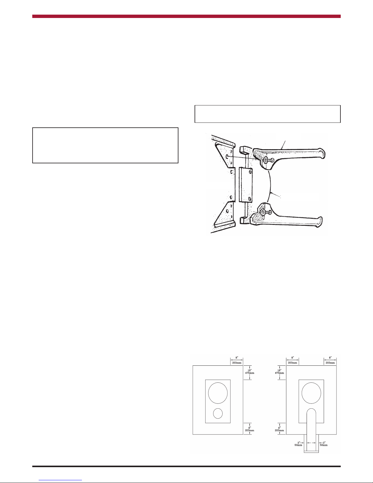
FLOOR PROTECTION
When installing this heater on a combustible floor, a
floor protector, consisting of a layer of non-combustible material at least
3
/8
” (9.5mm) thick or
1
/4
”
(6.4mm) thick covered with sheet metal is required
to cover the area under the heater and to extend to
at least 18” (457mm) a the front and 8” (203mm) to
the side and rear and this will provide protection
from sparks and embers which may fall out from the
door when stoking or fuelling.
WARNING: All the above parts must be fitted
to the stove before firing.
The complete installation must be done in accordance with current Standards and Local Codes. It
should be noted that the requirements and these
publications may be superseded during the life of
this manual.
Step 7: Install the Hot Plate (16) into the large
opening of Hob (14). Do not remove the hot plate
when the stove is lighting.
Step 8: Attach the spigot (15) to the back panel (12)
or the hob (14) as required with the
1
/4
” (6.4mm)
countersunk screws provided. Fit the back sealing
plate (18) to whichever opening is not used.
3
1. Leg
3. Base
2. Ashtray
Page 4
CHIMNEY
The Fionn Solid Fuel Stove must be connected to a
chimney of the correct size and type.
The chimney must have a CROSS-SECTIONAL
AREA of at least 30.sq. inches (176sq.cm) or a
diameter of at least 6” (15.2 cm). It is best to connect to a chimney of the same size, as connection to
a larger size may result in somewhat less draught.
Never connect to a smaller size chimney. Do not
connect to a chimney serving another appliance.
Minimum chimney height 15ft. (5m) from floor on
which stove is installed. An existing masonry chimney should be inspected, and if necessary repaired
by a competent mason. A steady draught condition
of 1.5mm (0.06 ins) WG is required for this stove.
CHIMNEY CONNECTORS
(Not Supplied)
The CHIMNEY CONNECTOR is a smokepipe used
to connect the Fionn Solid Fuel Stove to the chimney
described above. The CHIMNEY CONNECTOR
must be made of CORROSION RESISTANT STEEL
24 gauge of heavier (‘black’ or ‘blued’ or equivalent
treated steel), ENAMELLED CAST IRON or ENAMELLED STEEL of 6” (150mm) diameter.
SINGLE WALL STOVE PIPE MUST NOT PENETRATE COMBUSTIBLE WALLS OR CEILINGS.
INSTALLATION CLEARANCES
Maintain at least the following clearances to all
combustible material:
From the front 48” (1,219mm)
From the back 32” (820mm) straight up
only
From the sides 36” (914mm)
From the flue pipe 32
1
/4
” (812mm) straight up
only
It is recommended that this appliance is sited next to
and on a non-combustible surface. A minimum all
round clearance of 100 mm will allow air circulation
and not impede the performance of the stove.
CYLINDER
A 135 litre (30 Gallon) indirect cylinder with 25mm
(1” bore) flow is suitable and the length of pipes from
the cylinder to the stove should not exceed 7.8
metres (251/2) feet. There must be no gate valves
on this circuit and it must have an expansion pipe
exhausting to atmosphere. Cylinder and pipe work
should be lagged to minimise heat loss.
BACK CHIMNEY CONNECTORS
The stove may be installed at zero clearance to a
tiled fireplace or masonry wall
PLUMBING
(Boiler Model)
REGULATIONS
The Plumbing must be in accordance with all relevant regulations and practices. It must include a
gravity circuit with expansion pipe, open to the
atmosphere. The central heating will normally be
pump-driven as with other types of boilers.
GRAVITY CIRCUIT
The gravity circuit consists of the domestic hot water
tank o f 135 litres indirect cylinder, fixed in an upright
position, recommended for hot water storage and it
should be connected to the boiler by 25mm (1”)
diameter and return piping. The pipes should not
exceed flow 3.7m in length and anything in excess
of 2.0m must be fully lagged. The shorter the run of
pipe work the more effective the water heating. The
cylinder should be fully lagged.
Do not have any gate valves on this circuit.
4
6” (150mm)
Connector Pipe
Increaser
Page 5

Back chimney connection
into existing fireplace or
solid masonry wall.
Height to centre of back
outlet 530mm (20
7
/8)
5
mostat to the flow pipe of the gravity circuit and
wiring it into the pump control will ensure rapid circulation of the hot water.
PIPE THERMOSTAT
The fitting of a pipe thermostat to the flow pipe is
essential in order to activate the water circulation
pump when the water reaches the selected temperature.
When the water temperature falls below the selected temperature the pipe thermostat will cut off the
water circulation pump in order to allow the boiler to
recover.
OPERATING INSTRUCTIONS
COAL BURNING
LIGHTING THE FIRE
Thoroughly check all pipe work for leaks, especially
the pipe connections to the boiler before lighting.
Allow the stove to build up heat slowly at first.
Check that all dampers and catches are operating
correctly and ensure that all flue connections are
thoroughly sealed.
Fully open the Spin Valve and Back Air Valve and
kindle with paper and sticks in the usual way and
ignite by using a taper or rolled wad of paper. Under
no circumstances should any inflammable liquid i.e.
petrol, paraffin etc. be used to light the fire. When
the fire is well established adjust the spin valve and
back air valve. Add fuel to the firebox as required
and adjust the air valves to suit current requirements.
When refuelling open the spin valve before opening
the door as this will help to eliminate smoking, afterwards be sure to reset the spin valve and back air
valve to get maximum output from the boiler. Never
pack fuel tightly or fill the firebox to capacity. A low
INJECTOR TEE
Where the gravity and central heating circuits join
together to return the stove we recommended the
use of an injector tee connection, situation as close
to the unit as possible. This type of tee encourages
a stable flow of hot water through both circuits and
helps to prevent priority being given to the stronger
flow, which is most commonly the pumped central
heating circuit. This way, there will be no shortage
of hot water to the taps when the heating is on.
WATER CIRCUIT TEMPERATURE
The return water temperature should be maintained
at not less than 40oC so as to avoid condensation
on the boiler and return piping. Fitting a pipe ther-
Injector Tee
Pipe Thermostat
Indirect
Cylinder
Header
Tank
1” Bore
Flow &
Return
Radiator
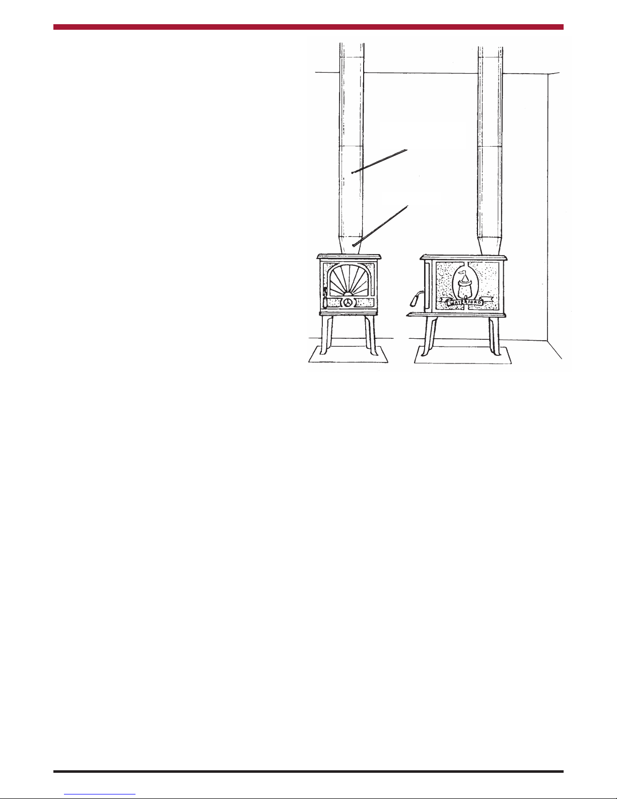
6” (150mm)
Connector Pipe
Combustible
Material
Increaser
Pump
Expansion
Pipe
Boiler
Function Diagram
Back Air
Valve
Window Air Wash
Secondary Air
Ashpan
Control
Handle
Spin
Valve
Page 6

level fire is more effective, particularly in regard to
water heating efficiency. The maximum fuel level is
up to the front lip of the coal grate and angled backwards at approximately 150o.
It is not unusual for some condensation to form on
the boiler when the unit is first lit. Do not use the circulating pump until the water in the boiler has heated up. If, when the pump comes on, the return water
temperature is too low, condensation may persist.
In this case, allow the system to warm up gradually
by turning on the radiators in the central heating circuit one by one. Always be prepared for condensation when lighting from cold. To dry out condensation run the appliance for a time with the spin valve
and back air valve open, then reset them.
Attention should be paid to the amount of ash
that is allowed to build up in the firebox.
The ash should be removed from a high burning
coal fire after 6 hours, to prevent damaging or
burning out of the grate.
USE OF BACK AIR VALVE
This air inlet is situated on the back of the stove to
supply primary air through the back insulating plate
to the fire. Its purpose is to assist the combustion
activity at the back of the fire chamber.
The Back Air Valve has four settings: fully closed
1
/4
”
(6.4mm),
1
/2
” (12.7mm), and fully opened. These
settings are used in conjunction with spin valve settings of similar magnitude to give low, medium or
high burning rates. A little practice will familiarise
you with the best settings for your needs.
6
WOODBURNING
To burn wood, peat briquettes, bog peat or synthetic wood, burn directly on hearth, do not use a grate
or elevate fire. “Never use gasoline, gasoline type
lantern fuel, kerosene, charcoal lighter fluid or similar liquids to start or ‘freshen up’ a fire in this heater.
Keep all liquids well away from the heater while it is
in use.” Operate stove only with fuelling door
closed.
LIGHTING
Lay a few crumbled sheets of paper on the hearth,
then a few small sticks on the kindling to get the fire
started. Close the door, and close the Back Air
Valve and open the Spin Valve control ALL THE
WAY.
The fire will catch the kindling quickly, after which the
full size logs may be placed on top. After the logs
have caught fire adjust the Air controls front and
back to suit the heat requirements.
The logs will burn slowly towards the rear of the fire
chamber and the rate of burning is adjustable at all
times by means of the Air controls. The more air
(wider opening) the faster the burning. Do not overfire the stove.
Once they are well lighted, the logs need little attention. It is recommended that the draught be reduced
(smaller opening) after the logs are well lighted as
they will require little draught to maintain combustion.
When the fire is reduced to embers, open the door
and carefully rake the embers towards the front of
the fire chamber and reload with logs.
OVERNIGHT BURNING
Overnight burning is controlled by closing the front
spin valve fully or leaving it about half a turn open
depending on draught conditions. The Back Air
Valve is fully closed by pushing the control rod
underneath the ash tray fully home.
MAINTENANCE
Inspect the chimney flue weekly until a safe frequency is established. The burning of wood, particularly if it is not seasoned, may cause build up of
creosote. If creosote has accumulated it should be
removed to reduce the risk of a chimney fire. Should
this creosote become ignited an extremely hot chimney fire can result.
DISPOSAL OF ASHES
Remove ashes carefully.
Ashes should be placed in a metal container with a
tight-fitting lid. The closed container of ashes should
be placed on a non-combustible floor or on the
ground, well away from all combustible materials,
Back Baffle
Function Diagram
Back Air
Valve
Window Air Wash
Secondary Air
Control
Handle
Spin
Valve
Boiler
Page 7

pending final disposal. If the ashes are disposed of
by burial in soil or otherwise locally dispersed , they
should be retained in the closed container until all
cinders have thoroughly cooled.
GLASS WINDOW
The glass will clean itself when there is sufficient
heat generated by burning fuel. The Air Way system
provides preheated air which keeps the glass clean
even at low heat conditions.
RECOMMENDED FUELS
The stove output levels are assessed on standard
House Coals of good quality. Reduced outputs will
result when fuels of lower calorific values are used.
Wood logs up to 36 cm long are suitable.
All fuels should be stored under cover and kept as
dry as possible prior to use.
House Coal 25 - 75mm Calorific Value 7.2 kW/KG = 12,300 BTUS/LB
Timber - Firebox Size Calorific Value 5.0 kW/KG = 8,600 BTUS/LB
Peat Briquettes - Calorific Value 4.8 kW/KG = 8,300 BTUS/LB
Bog Peat - Calorific Value 3.4 kW/KG = 6,000 BTUS/LB
VITREOUS ENAMEL CLEANING
General cleaning must be carried out when the
stove is cool.
If this stove is finished in a high gloss vitreous
enamel, to keep the enamel in the best condition
observe the following tips:
1. Wipe over daily with a soapy damp cloth,
followed by a polish with a clean dry duster.
2. For stubborn deposits a soap impregnated
pad can be carefully used on the vitreous
enamel.
3. Use only products recommended by the
Vitreous Enamel Association, these products
carry the Vitramel label.
4. DO NOT USE ABRASIVE PADS OR OVEN
CLEANSERS CONTAINING CITRIC ACID
ON ENAMELLED SURFACES. ENSURE
THAT THE CLEANSER MANUFACTURERS INSTRUCTIONS ARE ADHERED TO.
7
CO ALARM
Waterford Stanley recommend the fitting of a CO
Alarm in the same room as the appliance, this is a
requirement under UK Building Regulations. Further guidance on the installation of a carbon monoxide alarm is available in BS EN 50292:2002 and
from the alarm manufacturers instructions.
Provision of an alarm must not be considered a
substitute for either installing the appliance
correctly or ensuring regular servicing and
maintenance of the appliance and chimney
system.
WARNING:-
If the CO Alarm sounds unexpectedly:-
1. Open Doors and windows to ventilate the
room and then leave the premises.
2. Let the fire go out.
Page 8

8
1. LEG
2. ASH TRAY
3. BASE
4. BASE BAFFLE
5. SPIN VALVE
6. FIRE DOOR
7. SIDE
8. SIDE BRICK
9. INSIDE FIRE DOOR
10. DOOR LATCH
11. ASH PAN LIFTING TOOL
12. BACK PANEL
13. BOILER (INDIRECT
CYLINDER)
14. HOB
15. SPIGOT
16. HOTPLATE
17. FRONT FRAME
18. BACK SEALING PLATE
19. COAL GRATE (COAL
BURNING)
20. DOOR CATCH
21. ASHPAN (COAL BURNING)
22. WINDOW INSULATION
23. WINDOW GLASS
24. FIRE FENCE (WOOD
BURNING)
26. HEARTH PLATE (WOOD
BURNING)
27. BACK AIR VALVE HOUSING
28. BACK AIR VALVE
29. SEAL TO AIR VALVE
30. CONNECTING ROD TO
BACK AIR VALVE
31. GUIDE BRACKET TO BACK
AIR VALVE
32. NUT TO BOILER
33. DOOR SEALING ROPE
35. TOP BAFFLE (NON-BOILER)
36. BACK BAFFLE (NON-
BOILER)
EXPLODED VIEW
SECTION SHOWING INTERIOR OF STOVE
Page 9

FIONN SOLID FUEL STOVE SPECIFICATION
Height ................................................................................ 650mm 24
3
/4
ins.
Width.................................................................................. 370mm 14
1
/2
ins.
Depth.................................................................................. 630mm 24
3
/4
ins.
Flue Size............................................................................ 150mm dia. 6 ins. dia.
Height to centre of back of Flue Outlet............................. 530mm 20
7
/8
Fire Door Size................................................................... 264mm W x 280mm H 10
3
/8 ins. W x 11 ins. H
Log Size............................................................................ 360mm Long 14 ins. Long
Burning Rate (Coal).......................................................... 2.4 Kg/Hr 5.3 Lbs/Hr
Gross Output.................................................................... 19.0 kW/Hr 65,000 Btus/Hr
Radiation to Room........................................................... 7.3 kW/Hr 25,000 Btus/Hr
Max. Heat to Water.......................................................... 4.7 kW/Hr 16,000 Btus/Hr
Radiation Surface
Heating Surface Only....................................................... 8.6 sq. meters 92 sq. feet.
Heating Plus Domestic Hot Water................................... 3.7 sq. meters 40 sq. feet.
Gross Weight................................................................... 107 Kg 235 Lbs
It is of the utmost importance to keep the flue pipe and chimney clear of deposits by regular sweeping of the chimney. All
fuels give rise to soot or ash deposits and regular cleaning is essential for safe operation.
Blocked or partially obstructed flueways will cause dangerous fumes to be emitted into the room, these may well be
invisible if a smokeless fuel is burned.
Coal Burning
Wood Burning
9
Page 10

INSTALLATION CHECK LIST
Flue System
1. Minimum Flue Height of 4.6 metres (15 feet).
2. Appliance should be connected to a minimum of 1.8 metres (6 feet) of 150mm (6”)
flue pipe with a horizontal run not exceeding 150mm (6”).
3. Appliance should be connected to a chimney of less than 200mm (8”) in diameter
(otherwise the chimney must be lined with a 6” flue liner).
4. The chimney venting position must be above the main ridge of the roof or adjacent
outside obstructions.
5. The chimney serving this appliance should not serve any other appliance.
6. Access should be provided to the chimney serving the appliance to allow for cleaning.
Location
7. Clearance to combustible materials must be adhered to as described in the Clearance
to Combustible section.
8. The stove must be installed on a floor protector that covers the area under the stove
and extends 18” to the front & 8” to the sides and back.
Plumbing
9. Appliance must be connected to a gravity circuit using 1” ID flow & return piping.
10. The length of pipes from the cylinder to the cooker should not exceed 7.8 metres
(25
1
/2
feet).
11. A circulation pump should be fitted to the return pipe of the radiator circuit and controlled by
a pipe stat fitted to the flow pipe of the gravity circuit to the cylinder.
Ventilation & Combustion Air Requirements
12. The room in which the appliance is located should have an air vent of adequate
size to support correct combustion (see Ventilation & Combustion Air Requirement
Section for specific details).
Tick
10
Page 11

11
NOTES
Page 12

N00044AXX DP130903
Manufactured by
Waterford Stanley Ltd.,
Unit 401-403, IDA Industrial Estate, Cork Road,
Waterford, Ireland.
Tel: (051) 302300 Fax (051) 302315
12
 Loading...