

Page 1
TLM165S, TLM165SI, TLM330S
User Manual
Please read these instructions before operating the product.
www.2helpU.com
DOC100270398
GB
NL
GR
I
FIN
HU
BG
LV
D
DK
CZ
ES
NO
SK
RO
LT
F
SE
RU
PT
PL
SI
EE
TR
HR
Page 2
C
D
AAA
AAA
AAA
AAA
AAA
50.0°
0.7000 m
0.0000 m
0.0000 m
0.0000 m
50.0°
0.7760m
1.3470 m
0.4070 m
max
min
B
2
GB
A
2
1
3
Page 3

3
GB
F
4
3
1
2
7
5
6
50.0°
0.0000 m
0.0000 m
0.0000 m
0.0000 m
8
9
E
2
1
3
4
=
=
=
=
Page 4

4
GB
G
ft/m
TLM165S
TLM165SI
TLM330S
H
50.0°
0.0000 m
0.0000 m
0.0000 m
0.0000 m
a
a
1
2
3
Page 5
5
GB
I
K
50.0°
0.3000 m
0.7000 m
+
1.0000m
+
-
/
50.0°
0.1500 m
1.0000 m
-
0.8500m
+
-
/
L
J
50.0°
0.2400m
0.4000 m
0.6000 m
2
+
2
50.0°
0.4500 m
0.2400 m
0.2100 m
+
-
/
2
2
+/-
Page 6
6
GB
M
N
50.0°
1.0100m
2.7390 m
2.1000 m
?
O
?
P
50.0°
0.2100 m
0.5000 m
0.7000 m
0.6000 m
3
+
2.6520 m
0.0420 m
3
3
3
50.0°
2.6940 m
+
-
/
50.0°
0.0210 m
0.300 m
0.700 m
+/-
Page 7
7
GB
?
Q R
24.3°
4.8270m
0.0320 m
24.3°
?
50.0°
0.6000 m
3.0000 m
1.0000 m
2.0000 m
Page 8
8
GB
30.2°
9.8270 m
6.9320 m
30.2°
S
T
86.5°
15.0°
50.0°
Page 9
9
GB
U
12”
12”
12”
12”
50.0°
0.00 in
12.00 in
12.00 in
a
a
12” 12”
50.0°
0.00 in
12.00 in
12.00 in
a
a
12”
0.00 in
12.0 in
50.0°
a
a
12”
Page 10
10
GB
W
180°
90°
180°
?
86.5°
86.5°
V
Page 11
11
GB
Contents
• User Safety
• Battery Safety
• Setup (Load Batteries)
• Operation
• Warranty
• Error Codes
• Specications
Retain all sections of this manual for future
reference.
User Safety
WARNING:
Carefully read the Safety Instructions and
Product Manual before using this product.
The person responsible for the product
must ensure that all users understand and
adhere to these instructions.
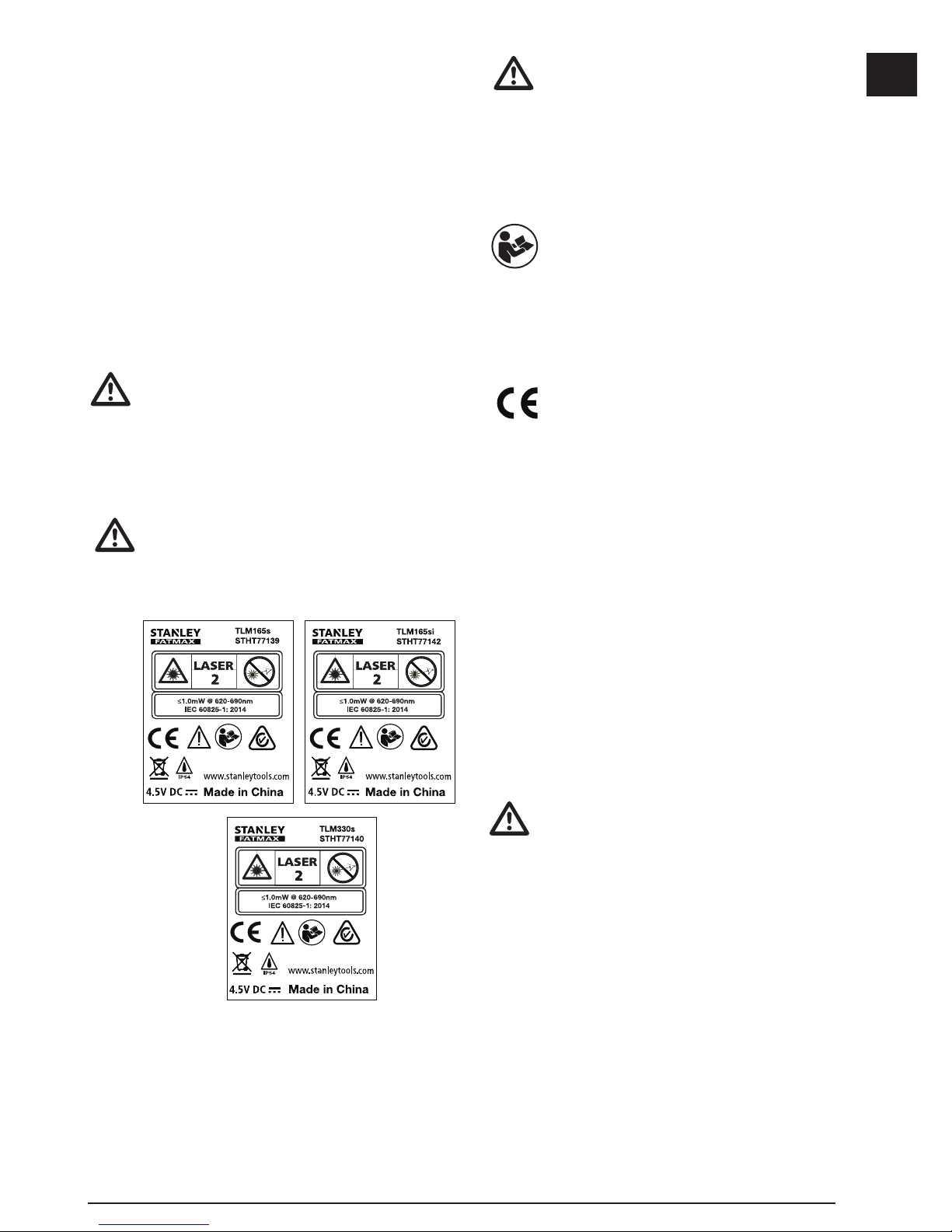
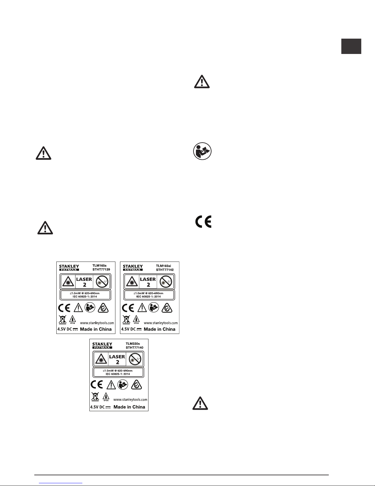
WARNING:
The following label information is placed
on your laser tool to inform you of the laser
class for your convenience and safety.
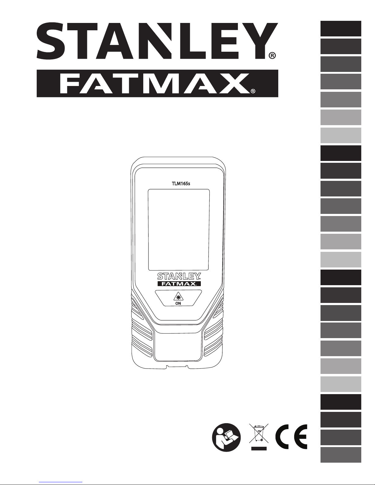
The TLM165S/TLM165SI/TLM330S tool
emits a visible laser beam, as shown in
Figure A. The laser beam emitted is Laser
Class 2 per IEC 60825-1 and complies with
21 CFR 1040.10 and 1040.11 except for
deviations pursuant to Laser Notice No. 50,
dated June 24, 2007.
WARNING:
While the laser tool is in operation, be
careful not to expose your eyes to the
emitting laser beam (red light source).
Exposure to a laser beam for an extended
time period may be hazardous to your eyes.
Do not look into the beam with optical aids.
WARNING: To reduce the risk of injury,
user must read the Product User manual,
Laser Safety manual, and Battery Safety
information.
EC-Declaration of Conformity
Radio Equipment Directive
Stanley Laser Distance Measurer
TLM165S, TLM165SI and TLM330S
Stanley hereby declares that the Stanley Laser
Distance Measurer TLM165S/TLM165SI/TLM330S is
in compliance with the Directive 2014/53/EU and to all
applicable EU directive requirements.
The full text of the EU Declaration of Conformity
can be requested at Stanley Tools, Egide
Walschaertsstraat 14-16, 2800 Mechelen, Belgium
or is available at the following internet address:
www.2helpU.com.
Search by the Product and Type Number indicated on
the nameplate.
Battery Safety
WARNING: Batteries can explode or leak
and cause serious injury or re. To reduce
the risk:
ALWAYS follow all instructions and
warnings on the battery label and package.
DO NOT short any battery terminals.
DO NOT charge alkaline batteries.
DO NOT mix old and new batteries.
Replace all of them at the same time with
new batteries of the same brand and type.
DO NOT mix battery chemistries.
DO NOT dispose of batteries in re.
ALWAYS keep batteries out of reach of
children.
Page 12
12
GB
ALWAYS remove batteries if the device will
not be used for several months.
NOTE: Ensure that the recommended
batteries are used.
NOTE: Ensure the batteries are inserted
in the correct manner, with the correct
polarity.
Loading Batteries
1.
Pull up the endpiece on the back of the tool
(Figure D 1).
2.
Pull up the battery compartment latch on the back
of the tool (Figure D 2 and D 3).
3.
Insert three AAA batteries, making sure to position
the - and + ends of each battery as noted inside
the battery compartment (Figure
D 4
).
4.
Push the battery door down until it snaps in place
(Figure D 5).
When the tool is ON, the battery level appears on the
screen (Figure
E 1
).
Turning the Tool On
1.
Point the tool's laser (Figure A 1) toward a wall
or object, and not toward anyone's eyes.
2.
Click (Figure A 3) to turn the tool on and
display the red laser dot.
Choosing the Settings
Setting Automatic Turn Off
By default, the tool will automatically turn off 90
seconds after no buttons or options have been
selected. To change when the tool turns off
automatically, follow these steps.
1.
On the touchscreen, click (Figure E 8).
2.
On the Settings Menu (Figure H), click .
3.
Select the time.
• Choose to turn the tool off after 30 sec, 60 secs,
90 secs, or 300 secs.
• To keep the tool turned on until you manually
turn it off (by pressing and holding
for
10 seconds), click
.
4.
Click to return to the previous screen.
Setting Screen Brightness
By default, the tool's screen will be set at 25%
brightness. To change the brightness level, follow
these steps.
1.
On the touchscreen, click (Figure E 8).
2.
On the Settings Menu (Figure H), click .
3.
Select the desired brightness level: 25%, 50%,
75%, or 100%.
4.
Click to return to the previous screen.
Turning Off the Sound
By default, the tool will beep each time you take
a measurement. You can turn off the beeps.
1.
On the touchscreen, click (Figure E 8).
2.
On the Settings Menu (Figure H), click to
display
.
3.
Click to return to the previous screen.
Changing the Unit of Measure
ft/m
By default, the tool will display measurements in
meters (1.8940 m). You can change the unit of
measure to fractional ft (6'02"
9/16), inches (74 9/16 in),
decimal ft (6.21 ft), or decimal inches (3.21 in).
1.
On the touchscreen, click (Figure E 8).
2.
On the Settings Menu (Figure H), click ft/m.
Page 13
13
GB
3.
Click the desired unit of measure.
• 0'00" 0/00
• 0" 0/00
• 0'00" ft
• 0.00 in
• 0.0000 m
4.
Click to return to the previous screen.
Choosing the Tool Position
By default, distances are measured from the bottom
of the tool to a wall or object (Figure
F 3
). To
measure distances from a different tool location, follow
these steps.
1.
On the touchscreen, select (Figure C 4).
2.
Select the tool position.
• To measure from the top of the tool
(Figure
F 1
), click .
• To measure from the tripod connection on the
tool (Figure
F 2
), click .
• To measure from a corner or another hard-toreach location with the endpiece flipped open
at the bottom of the tool (Figure
D 1
), click
(Figure F 4) to measure from the end of
the endpiece.
3.
Click to return to the previous screen.
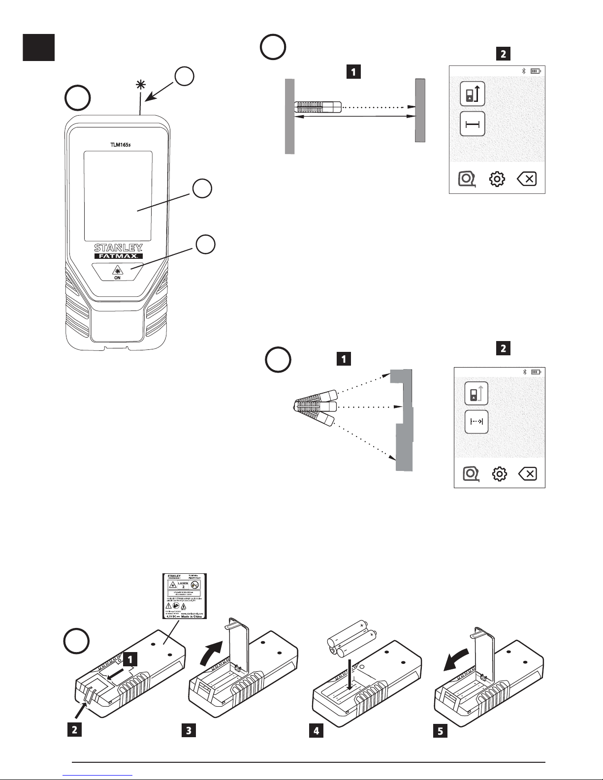
Taking Measurements
Measuring Distance
1.
Point the tool's laser (Figure A 1) toward a wall
or object, and not toward anyone's eyes.
2.
Press (Figure A 3) to turn the tool on and
display the red laser dot.
3.
Make sure the tool position setting (Figure E 4)
is correct for taking the measurement.
4.
If is not already displayed as the current
function (Figure E 5), click the current function
icon and then select
from the list of functions
(Figure G 1).
5.
Point the tool's laser (Figure A 1) toward
the wall or object whose distance you need to
measure (Figure
B 1
).
6.
Press to measure the distance from the tool
to the wall or object.
7
At the bottom of the screen, view the current
measurement (Figure B 2).
To take a new measurement, press
to move the
current measurement up to the previous line on the
screen. Then repeat steps 3-6.
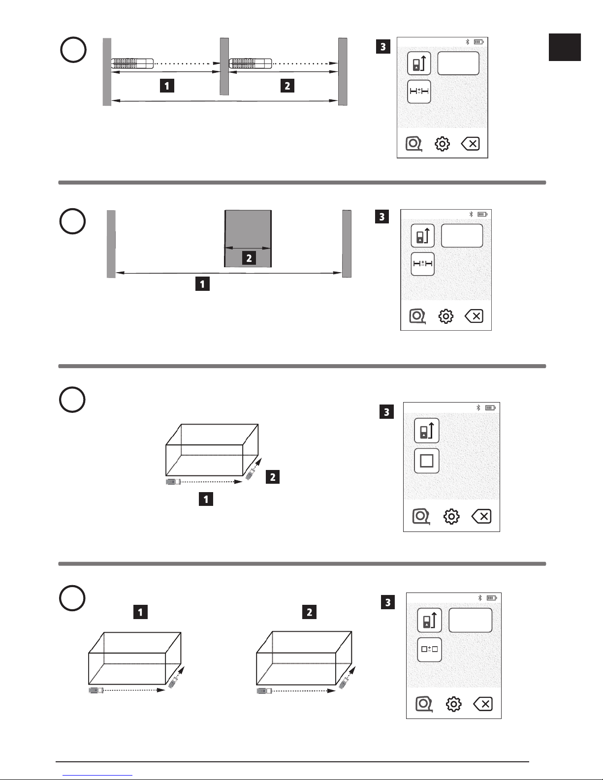
Adding 2 Measurements
You can add two measurements to get a total
measurement of the two distances (Figure I).
1.
Point the tool's laser (Figure A 1) toward a wall
or object, and not toward anyone's eyes.
2.
Press (Figure A 3) to turn the tool on and
display the red laser dot.
3.
Make sure the tool position setting (Figure E 4)
is correct for taking the measurement.
4.
If is not already displayed as the current
function (Figure E 5), click the current function
icon and then select
from the list of
functions (Figure G 1).
5.
Select + to indicate that you want to add
measurements.
6.
Point the tool's laser toward the first wall or object
whose distance you need to measure
(Figure
I 1
).
7.
Click to measure the distance from the tool to
the wall or object.
8.
Point the tool's laser toward the next wall or object
(Figure I 2).
9.
Press to measure the distance and add it to
the previous measurement.
10.
View the total of the two measurements at the
bottom of the screen (Figure I 3).
Page 14
14
GB
Subtracting 2 Measurements
You can subtract one measurement from another
(Figure
J
).
1.
Point the tool's laser (Figure A 1) toward a wall
or object, and not toward anyone's eyes.
2.
Press (Figure A 3) to turn the tool on and
display the red laser dot.
3.
Make sure the tool position setting (Figure E 4)
is correct for taking the measurement.
4.
If is not already displayed as the current
function (Figure E 5), click the current function
icon and then select
from the list of
functions (Figure G 1).
5.
Select - to indicate that you want to subtract one
measurement from another.
6.
Point the tool's laser toward the wall or object
whose distance you need to measure
(Figure
J 1
).
7.
Press to measure the distance from the tool
to the wall or object.
8.
Point the tool's laser toward the next wall or object
(Figure J 2).
9.
Press to measure the distance and subtract it
from the previous measurement.
10.
View the difference between the two
measurements at the bottom of the screen
(Figure
J 3
).
Measuring Continuously
To take a series of measurements as you move
around, change to Continuous Measure mode
(Figure C).
1.
Point the tool's laser (Figure A 1) toward a wall
or object, and not toward anyone's eyes.
2.
Press (Figure A 3) to turn the tool on and
display the red laser dot.
3.
Make sure the tool position setting (Figure E 4)
is correct for taking the measurement.
4.
If is not already displayed as the current
function (Figure E 5), click the current function
icon and then select
from the list of
functions (Figure G 1).
5.
Point the tool's laser (Figure A 1) toward
the wall or object whose distance you need to
measure (Figure
C 1
).
6.
At the bottom of the screen, view the current
measurement (Figure C 2), which will keep
changing as you move the tool.
7.
To take the current measurement (from the tool to
the wall or object) and exit Continuous Measure
mode, press
.
To take a new measurement, press
to move the
current measurement up to the previous line on the
screen. Then repeat steps 4-8.
Measuring Area
1.
Point the tool's laser (Figure A 1) toward a wall
or object, and not toward anyone's eyes.
2.
Press (Figure A 3) to turn the tool on and
display the red laser dot.
3.
Make sure the tool position setting (Figure E 4)
is correct for taking the measurement.
4.
If is not already displayed as the current
function (Figure E 5), click the current function
icon and then select
from the list of functions
(Figure G 1).
5.
Measure the width (Figure K 1).
• Position the tool at one end of the wall, floor,
or object and point the laser dot across the
width. (Figure
K 1
shows where to position
the tool if you are measuring from the bottom
of the tool.)
• Press
to display the width measurement at
the top of the screen.
Page 15
15
GB
6.
Measure the length (Figure K 2).
• Position the tool at one end of the wall, floor,
or object and point the laser dot across the
length. (Figure
K 2
shows where to position
the tool if you are measuring from the bottom
of the tool.)
• Press
to display the length measurement
on the second line of the screen.
7.
View the Area measurement at the bottom of the
screen (Figure K 3).
Adding/Subtracting 2 Areas
You can measure the area of a wall, floor, or object
and then add it to, or subtract it from, the area of
another wall, floor, or object (Figure L).
1.
Point the tool's laser (Figure A 1) toward a wall
or object, and not toward anyone's eyes.
2.
Press (Figure A 3) to turn the tool on and
display the red laser dot.
3.
Make sure the tool position setting (Figure E 4)
is correct for taking the measurement.
4.
If is not already displayed as the current
function (Figure E 5), click the current function
icon and then select
from the list of functions
(Figure G 2).
5.
Click + to add, or - to subtract, the areas of two
walls, floors, or objects.
6.
Measure the width of the first wall, floor, or object
(Figure L 1).
• Position the tool at one end of the target (wall,
floor, or object) and point the laser dot across
the width. (Figure
L 1
shows where to
position the tool if you are measuring from the
bottom of the tool.)
• Press
to display the width measurement at
the top of the screen.
7.
Measure the length of the first wall, floor, or
object (Figure L 2).
• Position the tool at one end of the target and
point the laser dot across the length. (Figure
L
2
shows where to position the tool if you are
measuring from the bottom of the tool.)
• Press
to display the length measurement
on the second line of the screen.
8.
Follow the same steps to measure the width and
length of the second wall, floor, or object.
9.
View the Area measurement at the bottom of the
screen (Figure L 3).
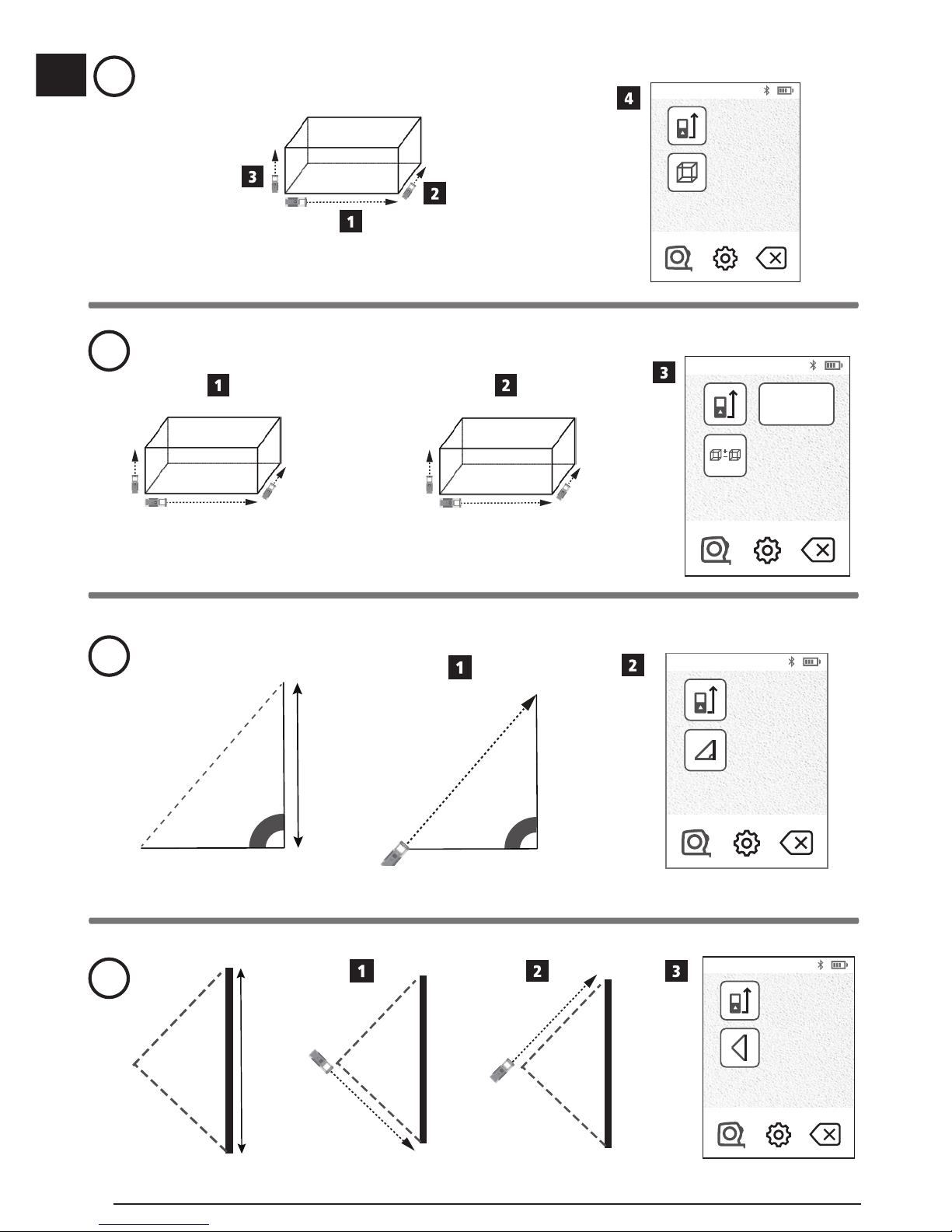
Measuring Volume
You can measure the volume of a room or object
(Figure M).
1.
Point the tool's laser (Figure A 1) toward a wall
or object, and not toward anyone's eyes.
2.
Press (Figure A 3) to turn the tool on and
display the red laser dot.
3.
Make sure the tool position setting (Figure E 4)
is correct for taking the measurement.
4.
If is not already displayed as the current
function (Figure E 5), click the current function
icon and then select
from the list of functions
(Figure G 1).
5.
Measure the width (Figure M 1).
• Position the tool at one end of the room or
object and point the laser dot across the width.
(Figure
M
1 shows where to position the
tool if you are measuring from the bottom of
the tool.)
• Press
to display the width measurement at
the top of the screen.
6.
Measure the length (Figure M 2).
• Position the tool at one end of the object and
point the laser dot across the length. (Figure
M
2
shows where to position the tool if you are
measuring from the bottom of the tool.)
• Press
to display the length measurement
on the second line of the screen.
Page 16
16
GB
7.
Measure the height (Figure M 3).
• Positon the tool at one end of the object and
point the laser dot across the height.
(Figure
M
3 shows where to position the
tool if you are measuring from the bottom of
the tool).
• Press
to display the height measurement
on the third line of the screen.
8.
View the Volume measurement at the bottom of
the screen (Figure M 4).
Adding/Subtracting 2 Volumes
You can measure the volume of room or object
and then add it to, or subtract it from, the volume of
another room or object (Figure N).
1.
Point the tool's laser (Figure A 1) toward a wall
or object, and not toward anyone's eyes.
2.
Press (Figure A 3) to turn the tool on and
display the red laser dot.
3.
Make sure the tool position setting (Figure E 4)
is correct for taking the measurement.
4.
If is not already displayed as the current
function (Figure E 5), click the current function
icon and then select
from the list of
functions (Figure G 2).
5.
Click + to add, or - to subtract, the volumes of two
objects.
6.
Measure the width (Figure N 1).
• Position the tool at one end of the object and
point the laser dot across the width.
(Figure
N 1
shows where to position the
tool if you are measuring from the bottom of
the tool.)
• Press
to display the width measurement at
the top of the screen.
7.
Measure the length (Figure N 2).
• Position the tool at one end of the object and
point the laser dot across the length. (Figure
N
2
shows where to position the tool if you are
measuring from the bottom of the tool.)
• Press
to display the length measurement on
the second line of the screen.
8.
Measure the height (Figure N 3).
• Position the tool at one end of the object and
point the laser dot across the height. (Figure
N
3
shows where to position the tool if you are
measuring from the bottom of the tool).
• Press
to display the height measurement on
the third line of the screen.
9.
Follow the same steps to measure the width,
length, and height of the second room or object.
10.
View the Volume measurement at the bottom of
the screen (Figure N 4).
Measuring the Height of a Tall Object
If you need to measure the height of a tall object
(e.g., a tall building), you can calculate the height
based on the distance to 1 point or the distances
from the same point to 2 points on the object. The
tool will use the Pythagorean Theorem (C2=A2+B2) to
calculate the height.
Distance to 1 Point
You can use the distance to one point on a wall
or object (Indirect Height) to determine its height
(Figure O).
1.
Point the tool's laser (Figure A 1) toward a wall
or object, and not toward anyone's eyes.
2.
Press (Figure A 3) to turn the tool on and
display the red laser dot.
3.
Make sure the tool position setting (Figure E 4)
is correct for taking the measurement.
4.
If is not already displayed as the current
function (Figure
E 5
), click the current function
icon and then select
from the list of functions
(Figure G 2).
5.
Position the tool opposite the bottom of the
vertical height to be measured (Figure O 1).
6.
Point the laser toward the highest point of the
building or object whose height you need to
measure (Figure
O 1
).
7.
Press to measure the distance.
8.
View the height measurement at the bottom of the
screen (Figure O 2).
Page 17
17
GB
Distances to 2 Points
You can use the distance to two points on a wall
or object (Double Indirect Height) to determine its
height (Figure P).
1.
Point the tool's laser (Figure A 1) toward a wall
or object, and not toward anyone's eyes.
2.
Press (Figure A 3) to turn the tool on and
display the red laser dot.
3.
Make sure the tool position setting (Figure E 4)
is correct for taking the measurement.
4.
If is not already displayed as the current
function (Figure E 5), click the current function
icon and then select
from the list of functions
(Figure G 2).
5.
Position the tool opposite the approximate
center of the vertical height to be measured
(Figure
P 1
).
6.
Point the laser toward the lowest point of the
building or object whose height you need to
measure (Figure
P 1
).
7.
Press to measure the distance.
8.
From the same point, aim the laser at the
highest point of the building or object
(Figure
P
2).
9.
Press to measure the distance.
10.
On the bottom line of the screen, view the height
of the building or object (Figure
P
3).
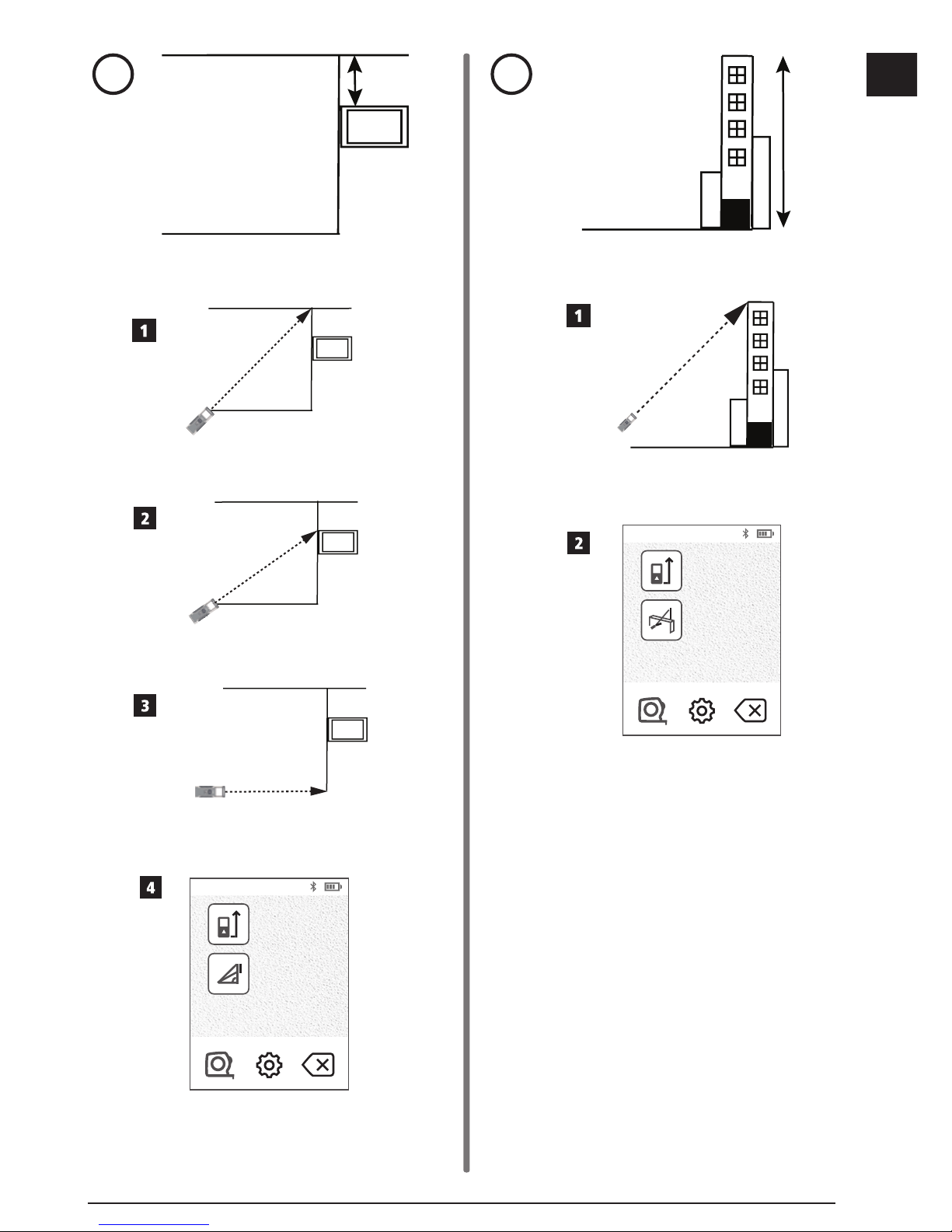
Measuring Partial Height
If you need to determine the height of a section of
a wall or object (e.g., the distance from the ceiling to
the top of TV or window on the wall) (Figure Q).
1.
Point the tool's laser (Figure A 1) toward a wall
or object, and not toward anyone's eyes.
2.
Press (Figure A 3) to turn the tool on and
display the red laser dot.
3.
Make sure the tool position setting (Figure E 4)
is correct for taking the measurement.
4.
If is not already displayed as the current
function (Figure E 5), click the current function
icon and then select
from the list of functions
(Figure G 2).
5.
Point the laser at the highest point of the wall or
object (Figure Q 1).
6.
Press to measure the distance to the top of
the object.
7.
From the same point, aim the laser at the top
of the obstruction (TV, window, etc.) on the wall
or object (Figure
Q
2).
8.
Press to measure the distance from the top
of the wall to the obstruction.
9.
From the same point, aim the laser on
a horizontal line straight ahead toward the
bottom of the wall (Figure
Q
3).
10.
Press to measure the distance.
11.
On the bottom line of the screen, view the
distance between the top of the wall and the top
of the obstruction on the wall (Figure
Q
4).
Measuring Height of Obstructed Object
Follow these steps to determine the height of a tall
building or object that is blocked by other buildings
or objects (Figure R).
1.
Point the tool's laser (Figure A 1) toward a wall
or object, and not toward anyone's eyes.
2.
Press (Figure A 3) to turn the tool on and
display the red laser dot.
3.
Make sure the tool position setting (Figure E 4)
is correct for taking the measurement.
4.
If is not already displayed as the current
function (Figure E 5), click the current function
icon and then select
from the list of functions
(Figure G 3).
5.
Point the laser at the highest point of the
building, wall, or object (Figure R 1).
6.
Press to take the measurement.
7.
On the bottom line of the screen, view the height
of the building or object (Figure R 2).
Page 18
18
GB
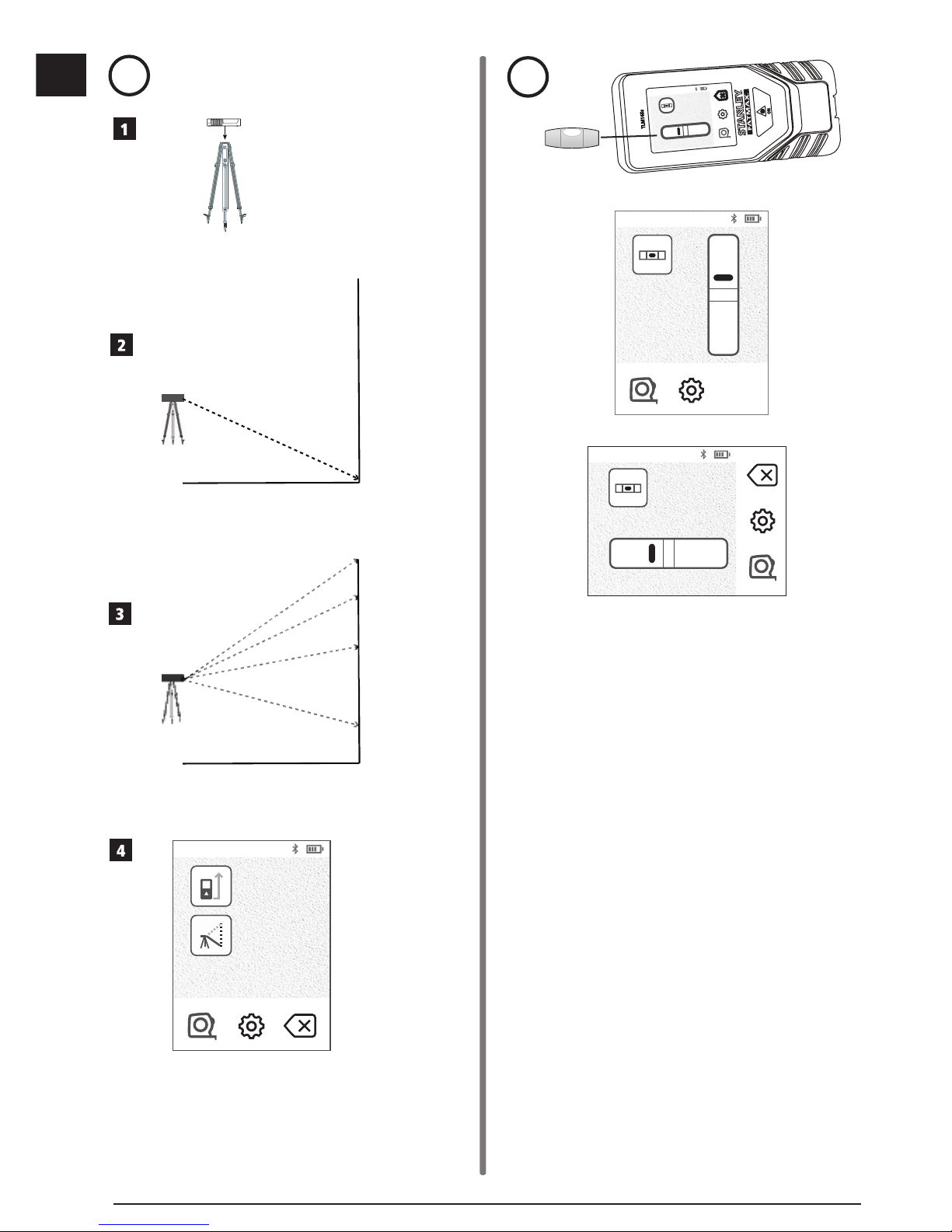
Measuring from a Tripod
If you are placing the tool on a tripod to measure
the height of a tall building, follow these steps
(Figure S).
1.
Screw the 1/4-20" hole on the back of the tool
onto the 1/4-20" connection on the top of your
tripod (Figure
S
1).
2.
Point the tool's laser (Figure A 1) toward a wall
or object, and not toward anyone's eyes.
3.
Press (Figure A 3) to turn the tool on and
display the red laser dot.
4.
Make sure the tool position setting (Figure E 4)
is
to measure from the tripod connection.
5.
If is not already displayed as the current
function (Figure E 5), click the current function
icon and then select
from the list of functions
(Figure G 3).
6.
Point the laser at the lowest point of the wall or
object whose height you need to measure
(Figure
S
2).
7.
Press to take the measurement.
8.
Point the laser at other points on the wall or object
(Figure S 3).
9.
When ready, press to take the measurement.
10.
On the bottom line of the screen, view the height
of the wall or object (Figure S 4).
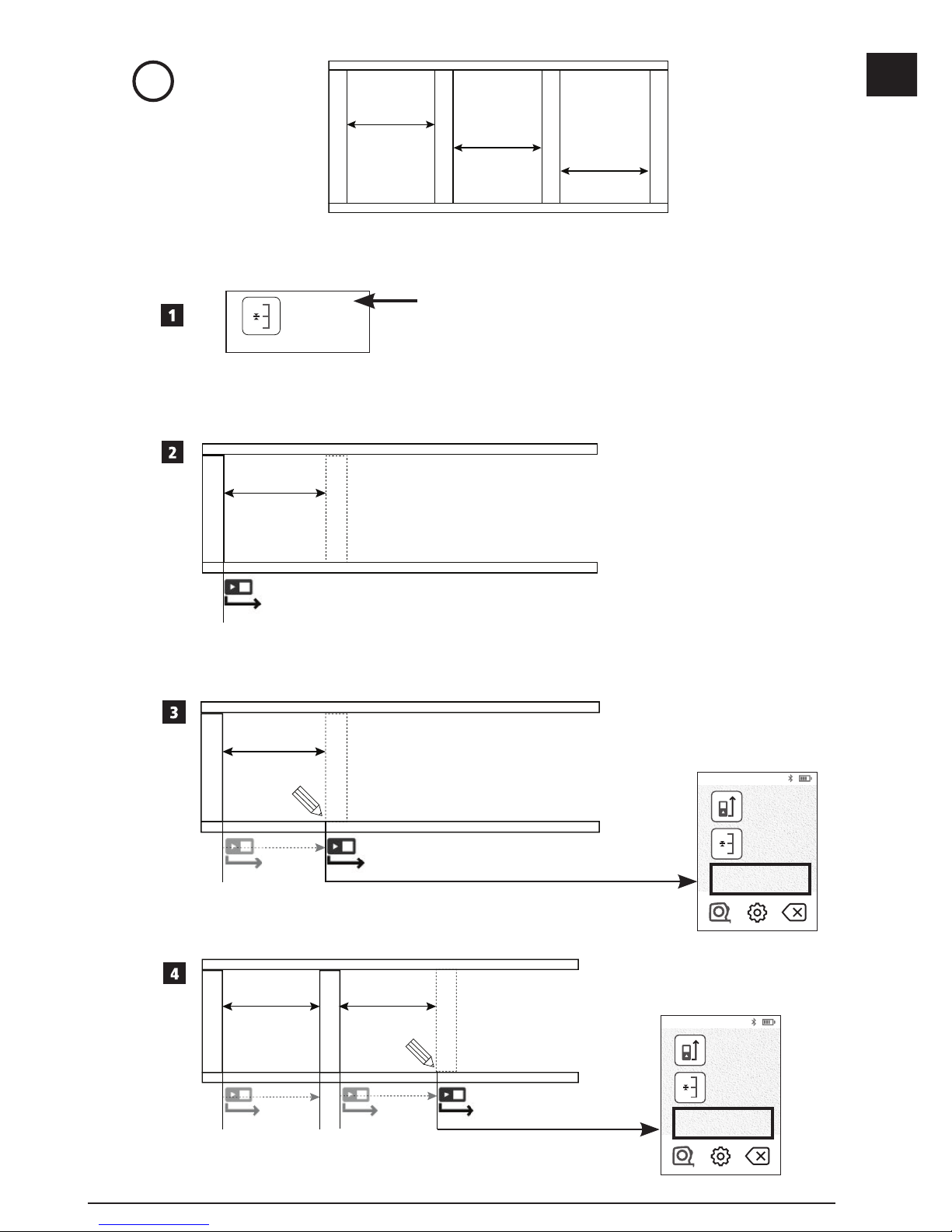
Positioning Studs
a
a
When you are framing a wall, use the Stakeout
feature to easily mark the position of each stud
(Figure
U
).
1.
Point the tool's laser (Figure A 1) toward a wall
or object, and not toward anyone's eyes.
2.
Press (Figure A 3) to turn the tool on and
display the red laser dot.
3.
Make sure the tool position setting (Figure E 4)
is set to to measure from the back of the tool.
4.
If
a
a
is not already displayed as the current
function (Figure E 5), click the current function
icon and then select
a
a
from the list of functions
(Figure G 3).
5.
Determine the distance between each stud, for
example, 12".
6.
Click + and - until the top number on the
screen is set to the distance from the right edge
of one stud to the left edge of the next (e.g., 12")
(Figure
U
1).
7.
Line up the back of the tool with the right edge of
the last stud that is nailed in (Figure U 2).
8.
Press to start measuring the distance as you
slowly move the tool to the right.
9.
Continue moving the tool to the right until the
bottom number on the screen is 0.00 in
(Figure
U
3).
10.
Press to stop measuring.
11.
Using a pencil, mark the location where the left
edge of the stud should be nailed into the wall
frame.
12.
Nail the left edge of the stud at the marked
location.
13.
For each remaining stud in the wall frame, repeat
steps 7-12 (Figure U 4).
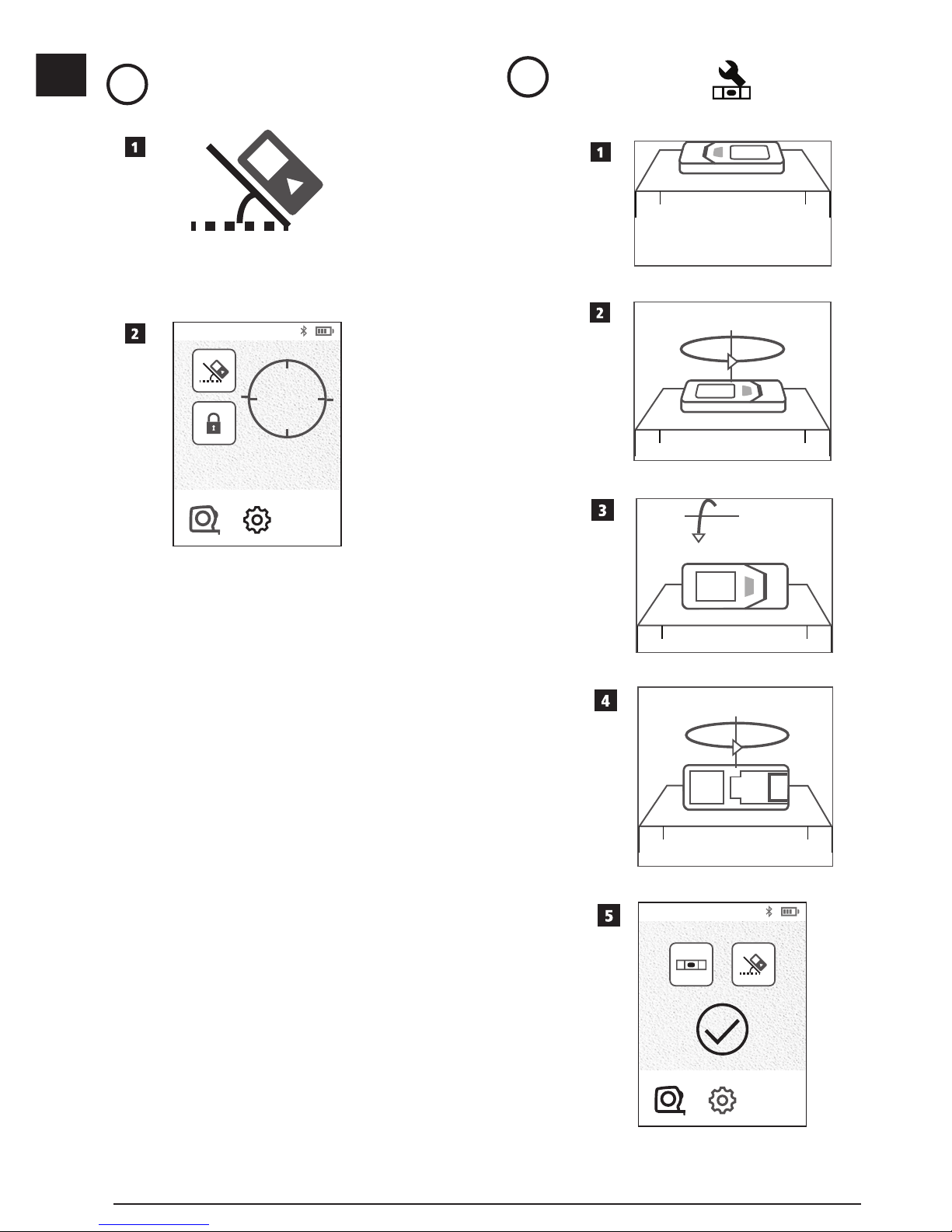
Measuring an Angle
If you need to determine the angle at which
something is positioned, use the tool to measure
that angle.
1.
Point the tool's laser (Figure A 1) toward a wall
or object, and not toward anyone's eyes.
2.
Press (Figure A 3) to turn the tool on and
display the red laser dot.
3.
Make sure the tool position setting (Figure E 4)
is correct for taking the measurement.
4.
If is not already displayed as the current
function (Figure E 5), click the current function
icon and then select
from the list of functions
(Figure G 2).
Page 19
19
GB
5.
Position the tool at the angle to be measured
(Figure V 1).
6.
Press to take the measurement.
7.
If you are measuring an angle that is at
a distance (e.g., overhead), click
to lock the
measurement on the screen before you move the
tool.
8.
Before using the tool again, click to unlock the
measurement (Figure
V
2).
Using the Tool as a Level
1.
Point the tool's laser (Figure A 1) toward a wall
or object, and not toward anyone's eyes.
2.
Press (Figure A 3) to turn the tool on and
display the red laser dot.
3.
If is not already displayed as the current
function (Figure C 5), click the current function
icon and then select
from the list of
functions.
4.
Place the tool in the vertical or horizontal position
on the surface that you want to check is level.
5.
On the tool's screen, view the position of the white
bubble on the vial (Figure T).
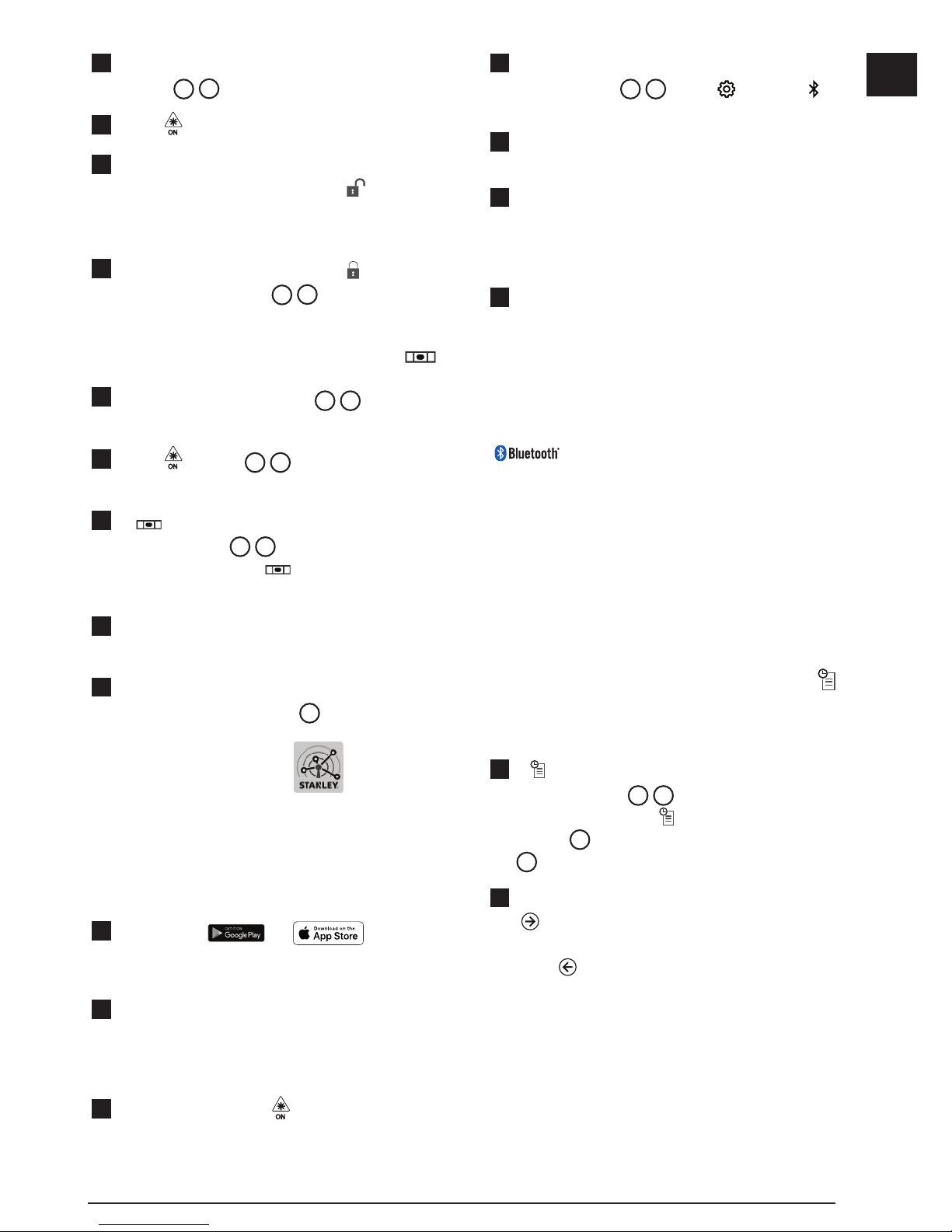
Using the Tool With
You can use the Bluetooth® capability of
your TLM165S, TLM165SI, or TLM330S to pair it
with the STANLEY
®
Smart Connect™ application
on your cell phone or tablet, and then record your
measurements on your floor plans or room photos.
1.
From either or , download
the STANLEY® Smart Connect™ application to
your cell phone or tablet.
2.
Using the STANLEY® Smart Connect™
application, capture the room or space for which
you want to record the measurements (either build
a floor plan or take room photos).
3.
On the keypad, press to turn on the tool.
4.
If the Bluetooth® icon does not appear on the
screen (Figure C 2), click and then to
turn on the Bluetooth
®
connection.
5.
Use the STANLEY® Smart Connect™ application
to pair your cell phone or tablet to the tool.
6.
Use the tool to measure each wall in the room
or space captured in the floor plan, and sync
the measurements to the floor plan, or enter the
measurements on the room photos.
7.
Using the STANLEY® Smart Connect™
application, save the floor plan or the marked up
photos.
Once you have saved the floor plan or marked up
photos, you can print them or email them to other
people (your realtor, home center, etc.).
THE BLUETOOTH® WORD MARK AND LOGOS ARE
REGISTERED TRADEMARKS OWNED BY BLUETOOTH SIG,
INC. AND ANY USE OF SUCH MARKS BY STANLEY TOOLS
IS UNDER LICENSE. APPLE AND THE APPLE LOGO ARE
TRADEMARKS OF APPLE INC., REGISTERED IN THE U.S.
AND OTHER COUNTRIES. APP STORE IS A SERVICE MARK
OF APPLE INC., REGISTERED IN THE U.S. AND OTHER
COUNTRIES. GOOGLE PLAY AND THE GOOGLE PLAY LOGO
ARE TRADEMARKS OF GOOGLE INC.
Viewing the Tool's Memory
Up to the last 20 measurements are stored in the
tool's memory.
1.
If is not already displayed as the current
function (Figure E 5), click the current function
icon and then select
from the list of functions
(Figure G
3
).
2.
View the last measurement that was taken. Click
to scroll through all the measurements that
have been stored in the tool's memory (up to 20).
Click
to scroll back.
Page 20
20
GB
Clearing the Tool's Memory
You can clear one or more measurements that are
currently in the tool's memory.
Clearing a Measurement
1.
If is not already displayed as the current
function (Figure E 5), click the current function
icon and then select
from the list of functions
(Figure G 3).
2.
Click or to scroll through the
measurements that have been stored in the
tool's memory (up to 20) until you display the
measurement to be deleted.
3.
Click .
4.
Click to delete the measurement.
Clearing All Memory
1.
If is not already displayed as the current
function (Figure E 5), click the current function
icon and then select
from the list of functions.
2.
Click .
3.
Click to delete ALL measurements from the
tool's memory.
Turning Off the Tool
The tool can be turned off in either of these ways:
• Press and hold
for 10 seconds. When you
release
after 10 seconds, the tool will turn off.
• If you do not use the tool for the number of seconds
(30, 60, or 300) you have set for auto turn off, it will
automatically turn off.
Calibrating the tool
Please note that if you do not position the tool correctly
for each step of the calibration process,
will appear
in red on the screen.
1.
On the touchscreen, click (Figure C 8).
2.
On the Settings Menu (Figure H), click .
3.
Place the tool with the front screen facing upward
on a flat, level surface (Figure W 1).
4.
Press .
5.
While the tool is still laying on the level surface,
turn the tool 180° (Figure W 2).
6.
Press .
7.
Flip the long side of the tool 90° so it is laying on
its side (Figure W 3).
8.
Press .
9.
While the tool is still laying on its side, turn the
tool 180° (Figure
W
4).
10.
Press .
11.
Make sure appears on the tool's screen
(Figure W 5).
12.
Click to return to the previous screen.
Warranty
STANLEY warrants this product for a period of Two (2)
years against deficiencies in material and workmanship.
This LIMITED WARRANTY does not cover products
that are improperly used, abused, altered, or repaired.
Please go to www.2helpU.com for more information or
return instructions. Unless otherwise noted, STANLEY
will repair without cost, any STANLEY product found
to be defective, including parts and labor charges, or
at STANLEY’s option, will replace such tools or refund
the purchase price, less the amount for depreciation,
in exchange for the defective tool. THIS LIMITED
WARRANTY EXCLUDES ALL INCIDENTAL OR
CONSEQUENTIAL DAMAGES. Some states do
not allow the exclusion or limitation of incidental or
consequential damages, so these limitations may not
apply to you. This TWO YEAR LIMITED WARRANTY
gives you specific legal rights that may vary from state
to state. In addition to the warranty, STANLEY Lasers
are covered by: 30-Day Money Back Guarantee. If you
are not completely satisfied with the performance of
your STANLEY Laser for any reason, you can return it
within 30 days from the date of purchase with a receipt
for a full refund.
Page 21
21
GB
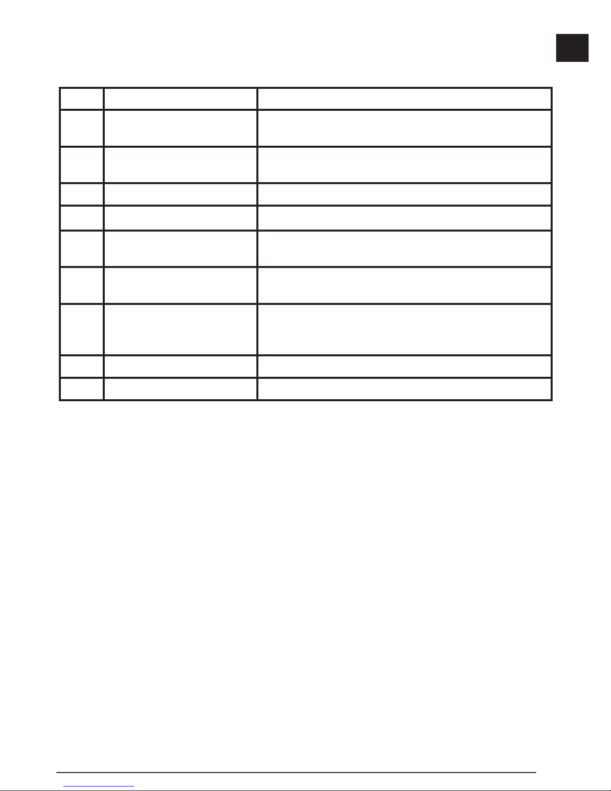
Error Codes
If INFO appears on the screen with a Code number, perform the corresponding Corrective Action.
Code Description Corrective Action
101 Received Signal Too Weak,
Measuring Time Too Long
Use the target plate or change the target surface.
102 Received Signal Too High Target is too reective. Use the target plate or change the
target surface.
201 Too Much Background Light Reduce the background light on the target area.
202 Laser Beam Interrupted Remove the obstacle and repeat the measurement.
301 Temperature Too High Allow the device to cool down to a temperature within the
specied Operating Temperature Range.
302 Temperature Too Low Allow the device to warm up to a temperature within the
specied Operating Temperature Range.
401 Hardware Error Switch the device on/off several times. If the error still occurs,
return the defective device to the Service Center or distributor.
Refer to the Warranty.
402 Unknown Error Contact the Service Center or distributor. Refer to the Warranty.
500 Data Error Contact the Service Center or distributor. Refer to the Warranty.
Page 22
22
GB
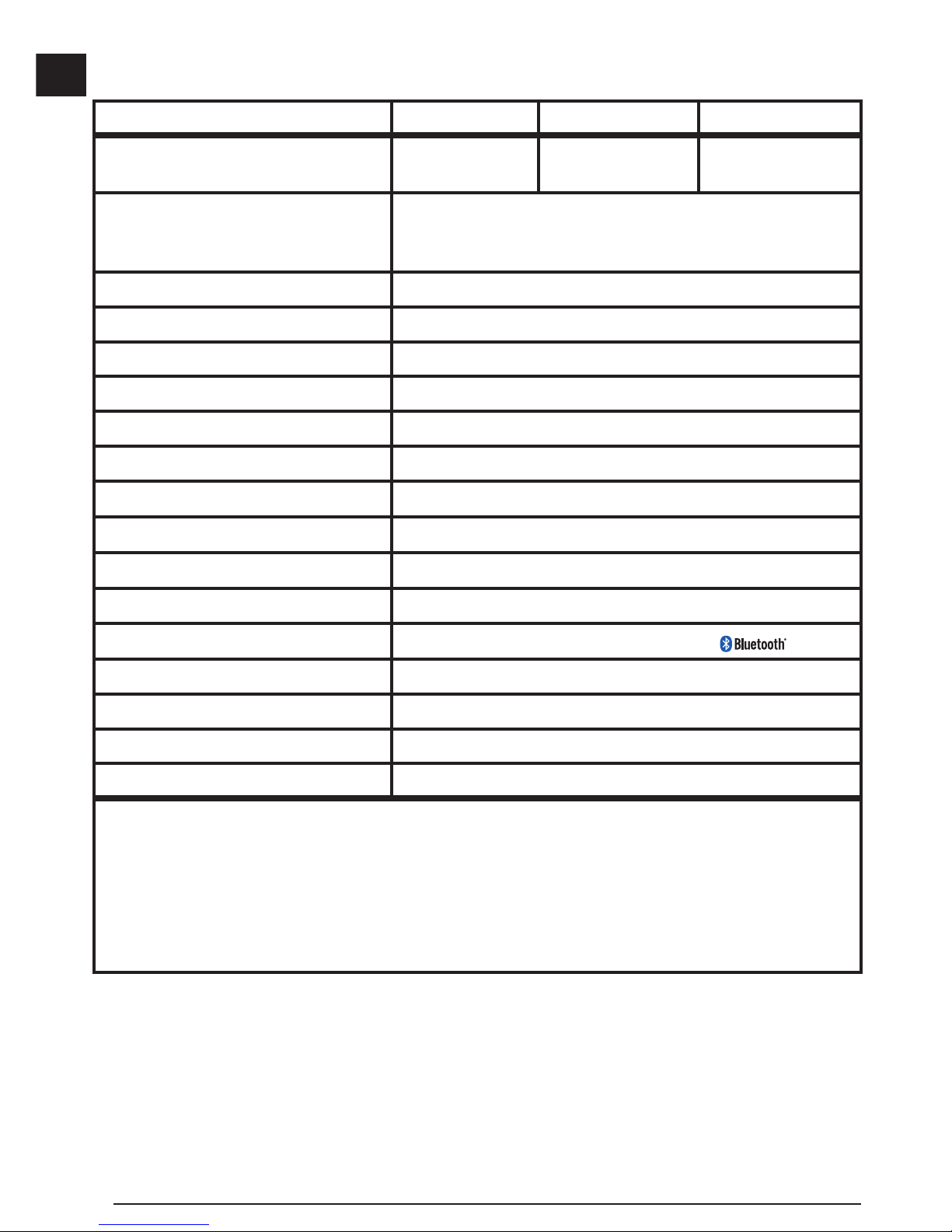
Specications
TLM165S TLM165SI TLM330S
Range 6in to 165ft
(0.15m to 50m)
6in to 197ft
(0.15m to 60m)
6in to 330ft
(0.15m to 100m)
Measuring Accuracy
1
up to 10m: 1/16in (1.5mm)
10m-30m: 0.078/5/64in) additional (+/- 0.15mm/m)
>30m: +/- 0.002in/ft (+/- 0.2mm/m)
Resolution
2
1/16in (1mm)
Laser Class Class 2 (IEC/EN60825-1: 2014)
Laser Type ≤ 1.0mW @ 620-690nm
Laser Automatic Switch-off 30s
Unit Automatic Switch-off By default, 90s. User can set to 30s, 60s, or 300s
Continuous Measuring Yes
Area Yes
Volume Yes
Pythagoras 2-Point Yes
Endpiece to measure from corners
3
Yes
Battery Life (3 x AAA)
Up to 3000 Measurements (2500 with
)
Dimension (H x D x W) 4.72 x 1.91 x 1.02in (120 x 48.5 x 26mm)
Weight (with Batteries) 9.88oz (280g)
Storage Temperature Range 14° F ~ 140° F (-10° C ~ +60 C)
Operating Temperature Range 32° F ~ 104° F (0° C ~ +40° C)
1
Measuring Accuracy depends on the current conditions:
• Under favorable conditions (good target surface and room temperature), up to 33ft (10m).
• Under unfavorable conditions (bright sunlight, a very weak reecting target surface, or large temperature uctuations), the
error can increase to ± 0.002 in/ft (± 0.2mm/m) for distances over 33ft (10m).
2
Resolution is the nest measurement you can see. In inches, that is 1/16". In mm, that is 1mm.
3
Flip open the endpiece at the bottom of the tool when you need to t the tool into corners or grooves that are not at 180° angles. If
a corner is at 90°, the endpiece can be used to hold the tool up against something.
Page 23
23
D
Inhalt
• Benutzersicherheit
• Sicherer Umgang mit Batterien
• Vorbereitung (Batterien einlegen)
• BETRIEB
• Gewährleistung
• Fehlercodes
• Technische Daten
Bewahren Sie alle Teile dieses Handbuchs zum
späteren Nachschlagen auf.
Benutzersicherheit
WARNUNG:
Lesen Sie alle Sicherheits- und
Bedienungsanweisungen, bevor Sie
dieses Produkt verwenden. Die Person,
die für das Produkt verantwortlich ist, muss
dafür sorgen, dass alle Benutzer diese
Anweisungen verstehen und sich an sie
halten.
WARNUNG:
Das folgende Informationsetikett auf dem
Laserwerkzeug informiert Sie zu Ihrer
Sicherheit über die Laser-Klasse.
Das Werkzeug TLM165S/TLM165SI/TLM330S gibt
einen sichtbaren Laserstrahl aus, siehe Abbildung.
Der ausgegebene Laserstrahl entspricht Laserklasse
2 gemäß IEC 60825-1 und erfüllt 21 CFR 1040.10
und 1040.11, außer bezüglich Abweichungen gemäß
Laser Notice No. 50 vom 24. Juni 2007.
WARNUNG:
Während das Laserwerkzeug in Betrieb
ist, darauf achten, nicht in den Laserstrahl
(rote Lichtquelle) zu blicken. Eine längere
Belastung durch Laserstrahlen kann den
Augen schaden. Nicht mit Hilfe von optischen
Hilfsmitteln in den Strahl blicken.
WARNUNG: Um das Risiko von
Verletzungen zu verringern, muss der
Benutzer das Produkthandbuch sowie das
Handbuch zum sicheren Umgang mit Lasern
und die Hinweise zu Batterien lesen.
EG-Konformitätserklärung
Funkgeräterichtlinie
Stanley Laser-Entfernungsmesser
TLM165S, TLM165SI und TLM330S
Stanley erklärt hiermit, dass der Stanley LaserEntfernungsmesser TLM165S/TLM165SI/TLM330S
der Richtlinie 2014/53/EU und allen geltenden EURichtlinienanforderungen entspricht.
Der vollständige Text der EU-Konformitätserklärung
kann bei Stanley Tools, Egide Walschaertsstraat
14-16, 2800 Mechelen, Belgien, oder unter folgender
Internetadresse angefordert werden: www.2helpU.
com.
Suchen Sie nach der auf dem Typenschild
angegebenen Produkt- und Typnummer.
Sicherer Umgang mit
Batterien
WARNUNG: Batterien können explodieren
oder auslaufen und dadurch Verletzungen
oder Feuer verursachen. Zum Reduzieren
von Risiken:
Befolgen Sie IMMER die Anleitungen und
Warnhinweise auf dem Etikett des Batterien
und der Verpackung.
Page 24

D
24
Schließen Sie Batterieklemmen NICHT kurz.
NICHT versuchen, Alkali-Batterien
aufzuladen.
Verwenden Sie NICHT gleichzeitig alte und
neue Batterien. Ersetzen Sie alle Batterien
gleichzeitig durch neue Batterien der gleichen
Marke und des gleichen Typs.
Verwenden Sie NICHT gleichzeitig
Batterien mit unterschiedlicher chemischer
Zusammensetzung.
Entsorgen Sie Batterien NICHT im Feuer.
Halten Sie Kinder IMMER von Batterien fern.
Entfernen Sie IMMER die Batterien, wenn ein
Gerät mehrere Monate nicht gebraucht wird.
HINWEIS: Stellen Sie sicher, dass die
empfohlenen Batterien verwendet werden.
HINWEIS: Stellen Sie sicher, dass die
Batterien richtig herum, d.h. mit der richtigen
Polarität eingesetzt sind.
Batterien einlegen
1.
Ziehen Sie das Endstück an der Rückseite des
Werkzeugs nach oben (Abbildung D 1).
2.
Ziehen Sie die Batteriefachsicherung sich an der
Rückseite des Werkzeugs nach oben
(Abbildung
D 2
und D 3).
3.
Legen Sie drei AAA-Batterien ein und
stellen Sie dabei sicher, dass die mit - und +
gekennzeichneten Enden jeder Batterie richtig
herum im Batteriefach liegen (Abbildung
D 4
).
4.
Drücken Sie die Abdeckung nach unten, bis sie
einrastet (Abbildung D 5).
Wenn das Werkzeug eingeschaltet ist, wird auf dem
Bildschirm der Batteriestand angezeigt
(Abbildung
E 1
).
Einschalten des
Werkzeugs
1.
Richten Sie den Laser des Werkzeugs
(Abbildung A 1) auf eine Wand oder einem
Gegenstand und nicht auf die Augen von
Personen.
2.
Drücken Sie auf (Abbildung A 3), um
das Werkzeug einzuschalten und den roten
Laserpunkt anzuzeigen.
Wählen der
Einstellungen
Einstellen der automatischen
Abschaltung
Das Werkzeug wird standardmäßig automatisch nach
90 Sekunden deaktiviert, wenn in der Zeit keine Tasten
betätigt oder Optionen ausgewählt wurden. Gehen Sie
folgendermaßen vor, um zu ändern, wann sich das
Werkzeug automatisch ausschaltet.
1.
Drücken Sie auf dem Touchscreen auf
(Abbildung E 8).
2.
Drücken Sie im Menü „Einstellungen“
(Abbildung H) auf .
3.
Wählen Sie die Zeit aus.
• Wählen Sie, ob sich das Gerät nach 30, 60, 90
oder 300 Sekunden ausschalten soll.
• Damit das Werkzeug eingeschaltet bleibt, bis
Sie es von Hand ausschalten (indem Sie
10 Sekunden lang gedrückt halten), drücken
Sie auf
.
4.
Drücken Sie auf , um zum vorherigen
Bildschirm zurückzukehren.
Page 25
25
D
Einstellen der Bildschirmhelligkeit
Standardmäßig ist der Bildschirm des Werkzeugs
auf eine Helligkeit von 25% eingestellt. Gehen Sie
folgendermaßen vor, um die Helligkeitsstufe zu
ändern.
1.
Drücken Sie auf dem Touchscreen auf
(Abbildung E 8).
2.
Drücken Sie im Menü „Einstellungen“
(Abbildung H) auf .
3.
Wählen Sie die gewünschte Helligkeitsstufe: 25%,
50%, 75% oder 100%.
4.
Drücken Sie auf , um zum vorherigen
Bildschirm zurückzukehren.
Ausschalten des Signaltons
Standardmäßig gibt das Werkzeug bei jeder Messung
einen Signalton aus. Sie können die Signaltöne
jedoch abstellen.
1.
Drücken Sie auf dem Touchscreen auf
(Abbildung E 8).
2.
Drücken Sie im Menü „Einstellungen“
(Abbildung H) auf , um anzuzeigen.
3.
Drücken Sie auf , um zum vorherigen
Bildschirm zurückzukehren.
Ändern der Maßeinheit
ft/m
Standardmäßig zeigt das Werkzeug Messungen in
Metern an (1,8940 m). Sie können die Anzeige der
Maßeinheit so ändern, dass sie als Bruch in Fuß (ft)
(6'02"
9/16), Zoll (74 9/16 in), Dezimalfuß (6,21 ft), oder
Dezimalzoll (3,21 in) angezeigt wird.
1.
Drücken Sie auf dem Touchscreen auf
(Abbildung E 8).
2.
Drücken Sie im Menü „Einstellungen“
(Abbildung H) auf ft/m.
3.
Klicken Sie auf die gewünschte Maßeinheit.
• 0'00" 0/00
• 0" 0/00
• 0'00" ft
• 0.00 in
• 0.0000 m
4.
Drücken Sie auf , um zum vorherigen
Bildschirm zurückzukehren.
Auswählen der Werkzeugposition
Standardmäßig werden Strecken vom Unterteil
des Werkzeugs bis zu einer Wand oder einem
Gegenstand gemessen (Abbildung F 3). Führen
Sie die folgenden Schritte aus, um Strecken von einer
anderen Werkzeugposition aus zu messen.
1.
Wählen Sie auf dem Touchscreen
(Abbildung C 4).
2.
Wählen Sie die Werkzeugposition.
• Zum Messen vom Oberteil des Werkzeugs aus
(Abbildung
F 1
) drücken Sie auf .
• Zum Messen vom Stativanschluss des
Werkzeugs aus (Abbildung
F 2
) drücken
Sie auf
.
• Zum Messen von einer Ecke oder einer anderen
schwer zu erreichenden Stelle, wobei das
Endstück unten am Werkzeug aufgeklappt
ist (Abbildung
D 1
), drücken Sie auf
(Abbildung F 4), um vom Ende des
Endstücks aus zu messen.
3.
Drücken Sie auf , um zum vorherigen
Bildschirm zurückzukehren.
Durchführen von
Messungen
Messung von Strecken
1.
Richten Sie den Laser des Werkzeugs (Abbildung
A 1
) auf eine Wand oder einem Gegenstand
und nicht auf die Augen von Personen.
Page 26
D
26
2.
Drücken Sie auf (Abbildung A 3), um
das Werkzeug einzuschalten und den roten
Laserpunkt anzuzeigen.
3.
Stellen Sie sicher, dass die Wahl der
Werkzeugposition (Abbildung E 4) die richtige
für die Durchführung der Messung ist.
4.
Wenn nicht bereits als aktuelle Funktion
angezeigt wird (Abbildung E 5), drücken Sie
auf das aktuelle Funktionssymbol und wählen Sie
aus der Liste der Funktionen aus
(Abbildung G 1).
5.
Richten Sie den Laser des Werkzeugs
(Abbildung A 1) auf die Wand oder das Objekt,
deren bzw. dessen Entfernung Sie messen wollen
(Abbildung
B 1
).
6.
Drücken Sie auf , um den Abstand von dem
Werkzeug zu der Wand oder dem Objekt zu
messen.
7
Lesen Sie unten auf dem Bildschirm den aktuellen
Messwert ab (Abbildung B 2).
Für eine weitere Messung drücken Sie auf
, um
das aktuelle Messergebnis in die vorherige Zeile des
Bildschirms zu verschieben. Wiederholen Sie dann
die Schritte 3-6.
2 Messungen addieren
Sie können zwei Messungen addieren, um eine
Gesamtmessung der beiden Strecken zu erhalten
(Abbildung I).
1.
Richten Sie den Laser des Werkzeugs
(Abbildung A 1) auf eine Wand oder einem
Gegenstand und nicht auf die Augen von
Personen.
2.
Drücken Sie auf (Abbildung A 3), um
das Werkzeug einzuschalten und den roten
Laserpunkt anzuzeigen.
3.
Stellen Sie sicher, dass die Wahl der
Werkzeugposition (Abbildung E 4) die richtige
für die Durchführung der Messung ist.
4.
Wenn nicht bereits als aktuelle Funktion
angezeigt wird (Abbildung E 5), drücken Sie
auf das aktuelle Funktionssymbol und wählen
Sie
aus der Liste der Funktionen aus
(Abbildung G 1).
5.
Wählen Sie +, um anzugeben, dass Sie
Messungen addieren möchten.
6.
Richten Sie den Laser des Werkzeugs auf die
erste Wand oder das erste Objekt, deren bzw.
dessen Abstand Sie messen wollen
(Abbildung
I 1
).
7.
Drücken Sie auf , um den Abstand von dem
Werkzeug zu der Wand oder dem Objekt zu
messen.
8.
Richten Sie den Laser des Werkzeugs auf
die nächste Wand oder das nächste Objekt
(Abbildung
I 2
).
9.
Drücken Sie auf , um die Strecke zu messen
und zu der vorherigen Messung zu addieren.
10.
Lesen Sie die Summe der beiden Messungen
unten auf dem Bildschirm ab (Abbildung I 3).
2 Messungen subtrahieren
Sie können ein Messergebnis von einem anderen
subtrahieren (Abbildung J).
1.
Richten Sie den Laser des Werkzeugs
(Abbildung A 1) auf eine Wand oder einem
Gegenstand und nicht auf die Augen von
Personen.
2.
Drücken Sie auf (Abbildung A 3), um
das Werkzeug einzuschalten und den roten
Laserpunkt anzuzeigen.
3.
Stellen Sie sicher, dass die Wahl der
Werkzeugposition (Abbildung E 4) die richtige
für die Durchführung der Messung ist.
4.
Wenn nicht bereits als aktuelle Funktion
angezeigt wird (Abbildung
E 5
), drücken Sie
auf das aktuelle Funktionssymbol und wählen
Sie
aus der Liste der Funktionen aus
(Abbildung
G 1
).
5.
Wählen Sie -, um anzugeben, dass Sie eine
Messung von einer anderen subtrahieren
möchten.
6.
Richten Sie den Laser des Werkzeugs auf die
Wand oder das Objekt, deren bzw. dessen
Entfernung Sie messen möchten
(Abbildung
J 1
).
Page 27
27
D
7.
Drücken Sie auf , um den Abstand von dem
Werkzeug zu der Wand oder dem Objekt zu
messen.
8.
Richten Sie den Laser des Werkzeugs auf
die nächste Wand oder das nächste Objekt
(Abbildung
J 2
).
9.
Drücken Sie auf , um die Strecke zu messen
und von der vorherigen Messung zu subtrahieren.
10.
Lesen Sie die Differenz zwischen den beiden
Messungen unten auf dem Bildschirm ab
(Abbildung
J 3
).
Dauermessung
Wenn Sie eine Reihe von Messungen durchführen
möchten, während Sie sich bewegen, wechseln Sie
zum Dauermessmodus (Abbildung C).
1.
Richten Sie den Laser des Werkzeugs
(Abbildung A 1) auf eine Wand oder einem
Gegenstand und nicht auf die Augen von
Personen.
2.
Drücken Sie auf (Abbildung A 3), um
das Werkzeug einzuschalten und den roten
Laserpunkt anzuzeigen.
3.
Stellen Sie sicher, dass die Wahl der
Werkzeugposition (Abbildung E 4) die richtige
für die Durchführung der Messung ist.
4.
Wenn nicht bereits als aktuelle Funktion
angezeigt wird (Abbildung
E 5
), drücken Sie
auf das aktuelle Funktionssymbol und wählen
Sie
aus der Liste der Funktionen aus
(Abbildung
G 1
).
5.
Richten Sie den Laser des Werkzeugs
(Abbildung A 1) auf die Wand oder das Objekt,
deren bzw. dessen Entfernung Sie messen wollen
(Abbildung
C 1
).
6.
Am unteren Bildschirmrand (Abbildung C 2)
sehen Sie den aktuellen Messwert, der sich
ständig verändert, wenn Sie das Werkzeug
bewegen.
7.
Um eine aktuelle Messung (vom Werkzeug zu der
Wand oder dem Objekt) durchzuführen und den
Dauermessmodus zu verlassen, drücken Sie auf
.
Für eine weitere Messung drücken Sie auf
, um
das aktuelle Messergebnis in die vorherige Zeile des
Bildschirms zu verschieben. Wiederholen Sie dann
die Schritte 4-8.
Messung von Flächen
1.
Richten Sie den Laser des Werkzeugs
(Abbildung A 1) auf eine Wand oder einem
Gegenstand und nicht auf die Augen von
Personen.
2.
Drücken Sie auf (Abbildung A 3), um
das Werkzeug einzuschalten und den roten
Laserpunkt anzuzeigen.
3.
Stellen Sie sicher, dass die Wahl der
Werkzeugposition (Abbildung E 4) die richtige
für die Durchführung der Messung ist.
4.
Wenn nicht bereits als aktuelle Funktion
angezeigt wird (Abbildung E 5), drücken Sie
auf das aktuelle Funktionssymbol und wählen Sie
aus der Liste der Funktionen aus (Abbildung
G 1
).
5.
Messen Sie die Breite (Abbildung K 1).
• Platzieren Sie das Werkzeug an einem Ende
der Wand, des Bodens oder Objekts und
richten Sie den Laserpunkt über die Breite.
(Abbildung
K 1
zeigt die richtige Position des
Werkzeugs, wenn Sie von der Unterseite des
Werkzeugs aus messen.)
• Drücken Sie auf
, um den Breitenmesswert
oben auf dem Bildschirm anzuzeigen.
6.
Messen Sie die Länge (Abbildung K 2).
• Platzieren Sie das Werkzeug an einem Ende
der Wand, des Bodens oder Objekts und
richten Sie den Laserpunkt über die Länge.
(Abbildung
K 2
zeigt die richtige Position des
Werkzeugs, wenn Sie von der Unterseite des
Werkzeugs aus messen.)
• Drücken Sie auf
, um den Längenmesswert
in der zweiten Zeile des Bildschirms
anzuzeigen.
7.
Lesen Sie die Fläche am unteren Bildschirmrand
ab (Abbildung K 3).
Page 28
D
28
2 Flächen addieren/subtrahieren
Sie können die Fläche einer Wand, eines Fußbodens
oder eines Objekts messen und ihn dann dem Bereich
einer anderen Wand, eines anderen Fußbodens
oder eines anderen Objekts hinzufügen oder von ihm
subtrahieren (Abbildung L).
1.
Richten Sie den Laser des Werkzeugs
(Abbildung A 1) auf eine Wand oder einem
Gegenstand und nicht auf die Augen von
Personen.
2.
Drücken Sie auf (Abbildung A 3), um
das Werkzeug einzuschalten und den roten
Laserpunkt anzuzeigen.
3.
Stellen Sie sicher, dass die Wahl der
Werkzeugposition (Abbildung
E 4
) die richtige
für die Durchführung der Messung ist.
4.
Wenn nicht bereits als aktuelle Funktion
angezeigt wird (Abbildung E 5), drücken Sie
auf das aktuelle Funktionssymbol und wählen Sie
aus der Liste der Funktionen aus
(Abbildung G 2).
5.
Drücken Sie auf + oder -, um die Flächen
von zwei Wänden, Böden oder Objekten zu
subtrahieren.
6.
Messen Sie die Breite der ersten Wand, des
ersten Fußbodens oder Objekts
(Abbildung
L 1
).
• Platzieren Sie das Werkzeug an einem Ende
des Ziels (Wand, Fußboden oder Objekt) und
richten Sie den Laserpunkt über die Breite.
(Abbildung
L 1
zeigt die richtige Position des
Werkzeugs, wenn Sie von der Unterseite des
Werkzeugs aus messen.)
• Drücken Sie auf
, um den Breitenmesswert
oben auf dem Bildschirm anzuzeigen.
7.
Messen Sie die Länge der ersten Wand, des ersten
Fußbodens oder Objekts (Abbildung L 2).
• Platzieren Sie das Werkzeug an einem Ende
des Ziels und richten Sie den Laserpunkt über
die Länge. (Abbildung
L 2
zeigt die richtige
Position des Werkzeugs, wenn Sie von der
Unterseite des Werkzeugs aus messen.)
• Drücken Sie auf
, um den Längenmesswert
in der zweiten Zeile des Bildschirms
anzuzeigen.
8.
Gehen Sie zum Messen der Breite und Länge
der zweiten Wand, des zweiten Fußboden oder
Objekts ebenso vor.
9.
Lesen Sie die Fläche am unteren Bildschirmrand
ab (Abbildung L 3).
Messen des Volumens
Sie können das Volumen eines Raumes oder Objekts
ermitteln (Abbildung M).
1.
Richten Sie den Laser des Werkzeugs
(Abbildung A 1) auf eine Wand oder einem
Gegenstand und nicht auf die Augen von
Personen.
2.
Drücken Sie auf (Abbildung A 3), um
das Werkzeug einzuschalten und den roten
Laserpunkt anzuzeigen.
3.
Stellen Sie sicher, dass die Wahl der
Werkzeugposition (Abbildung E 4) die richtige
für die Durchführung der Messung ist.
4.
Wenn nicht bereits als aktuelle Funktion
angezeigt wird (Abbildung E 5), drücken Sie
auf das aktuelle Funktionssymbol und wählen Sie
aus der Liste der Funktionen aus
(Abbildung G 1).
5.
Messen Sie die Breite (Abbildung M 1).
• Platzieren Sie das Werkzeug an einem Ende
des Raums oder Objekts und richten Sie den
Laserpunkt über die Breite. (Abbildung
M
1
zeigt die richtige Position des Werkzeugs,
wenn Sie von der Unterseite des Werkzeugs
aus messen.)
• Drücken Sie auf
, um den Breitenmesswert
oben auf dem Bildschirm anzuzeigen.
Page 29
29
D
6.
Messen Sie die Länge (Abbildung M 2).
• Platzieren Sie das Werkzeug an einem Ende
des Objekts und richten Sie den Laserpunkt
über die Länge. (Abbildung
M
2 zeigt die
richtige Position des Werkzeugs, wenn Sie von
der Unterseite des Werkzeugs aus messen.)
• Drücken Sie auf
, um den Längenmesswert
in der zweiten Zeile des Bildschirms
anzuzeigen.
7.
Messen Sie die Höhe (Abbildung M 3).
• Platzieren Sie das Werkzeug an einem Ende
des Objekts und richten Sie den Laserpunkt
über die Höhe.
(Abbildung
M
3 zeigt die richtige Position des
Werkzeugs, wenn Sie von der Unterseite des
Werkzeugs aus messen.)
• Drücken Sie auf
, um den Höhenmesswert
in der dritten Zeile des Bildschirms anzuzeigen.
8.
Lesen Sie das Volumen unten auf dem Bildschirm
ab (Abbildung M 4).
2 Volumen addieren/subtrahieren
Sie können die Volumen eines Raums oder Objekts
messen und sie dann zum Volumen eines anderen
Raums oder Objekts hinzufügen oder davon
subtrahieren (Abbildung N).
1.
Richten Sie den Laser des Werkzeugs
(Abbildung A 1) auf eine Wand oder einem
Gegenstand und nicht auf die Augen von
Personen.
2.
Drücken Sie auf (Abbildung A 3), um
das Werkzeug einzuschalten und den roten
Laserpunkt anzuzeigen.
3.
Stellen Sie sicher, dass die Wahl der
Werkzeugposition (Abbildung E 4) die richtige
für die Durchführung der Messung ist.
4.
Wenn nicht bereits als aktuelle Funktion
angezeigt wird (Abbildung E 5), drücken Sie
auf das aktuelle Funktionssymbol und wählen
Sie
aus der Liste der Funktionen aus
(Abbildung G 2).
5.
Drücken Sie auf + um die Volumen zweier Objekte
zu addieren, oder auf -, um sie zu subtrahieren.
6.
Messen Sie die Breite (Abbildung N 1).
• Platzieren Sie das Werkzeug an einem Ende
des Objekts und richten Sie den Laserpunkt
über die Breite. (Abbildung
N 1
zeigt die
richtige Position des Werkzeugs, wenn Sie von
der Unterseite des Werkzeugs aus messen.)
• Drücken Sie auf
, um den Breitenmesswert
oben auf dem Bildschirm anzuzeigen.
7.
Messen Sie die Länge (Abbildung N 2).
• Platzieren Sie das Werkzeug an einem Ende
des Objekts und richten Sie den Laserpunkt
über die Länge. (Abbildung
N 2
zeigt die
richtige Position des Werkzeugs, wenn Sie von
der Unterseite des Werkzeugs aus messen.)
• Drücken Sie auf
, um den Längenmesswert
in der zweiten Zeile des Bildschirms
anzuzeigen.
8.
Messen Sie die Höhe (Abbildung N 3).
• Platzieren Sie das Werkzeug an einem Ende
des Objekts und richten Sie den Laserpunkt
über die Höhe. (Abbildung
N 3
zeigt die
richtige Position des Werkzeugs, wenn Sie von
der Unterseite des Werkzeugs aus messen.)
• Drücken Sie auf
, um den Höhenmesswert
in der dritten Zeile des Bildschirms anzuzeigen.
9.
Gehen Sie zum Messen der Breite, Länge und
Höhe des zweiten Objekts ebenso vor.
10.
Lesen Sie das Volumen unten auf dem Bildschirm
ab (Abbildung N 4).
Messen der Höhe eines großen
Objekts
Wenn Sie die Höhe eines großen Objekts messen
wollen (z. B. eines hohen Gebäudes), können Sie
die Höhe basierend auf der Entfernung zu 1 Punkt
oder den Entfernungen von demselben Punkt zu 2
Punkten an dem Objekt berechnen. Das Werkzeug
nutzt den Satz des Pythagoras (C2=A2+B2), um die
Höhe zu berechnen.
Page 30
D
30
Entfernung zu 1 Punkt
Sie können die Entfernung zu einem Punkt an einer
Wand oder einem Objekt (indirekte Höhe) verwenden,
um seine Höhe zu bestimmen (Abbildung O).
1.
Richten Sie den Laser des Werkzeugs
(Abbildung A 1) auf eine Wand oder einem
Gegenstand und nicht auf die Augen von
Personen.
2.
Drücken Sie auf (Abbildung A 3), um
das Werkzeug einzuschalten und den roten
Laserpunkt anzuzeigen.
3.
Stellen Sie sicher, dass die Wahl der
Werkzeugposition (Abbildung E 4) die richtige
für die Durchführung der Messung ist.
4.
Wenn nicht bereits als aktuelle Funktion
angezeigt wird (Abbildung E 5), drücken Sie
auf das aktuelle Funktionssymbol und wählen Sie
aus der Liste der Funktionen aus
(Abbildung G 2).
5.
Platzieren Sie das Werkzeug gegenüber dem
unteren Ende der zu messenden vertikalen Höhe
(Abbildung
O 1
).
6.
Richten Sie den Laser auf den höchsten Punkt
des Gebäudes oder Objekts, dessen Höhe Sie
messen wollen (Abbildung
O 1
).
7.
Drücken Sie auf , um die Strecke zu messen.
8.
Lesen die Höhe am unteren Bildschirmrand ab
(Abbildung O 2).
Entfernungen zu 2 Punkten
Sie können die Entfernung zu zwei Punkten an einer
Wand oder einem Objekt (doppelte indirekte Höhe)
verwenden, um seine Höhe zu bestimmen
(Abbildung P).
1.
Richten Sie den Laser des Werkzeugs
(Abbildung A 1) auf eine Wand oder einem
Gegenstand und nicht auf die Augen von
Personen.
2.
Drücken Sie auf (Abbildung A 3), um
das Werkzeug einzuschalten und den roten
Laserpunkt anzuzeigen.
3.
Stellen Sie sicher, dass die Wahl der
Werkzeugposition (Abbildung E 4) die richtige
für die Durchführung der Messung ist.
4.
Wenn nicht bereits als aktuelle Funktion
angezeigt wird (Abbildung E 5), drücken Sie
auf das aktuelle Funktionssymbol und wählen Sie
aus der Liste der Funktionen aus
(Abbildung G 2).
5.
Platzieren Sie das Werkzeug gegenüber der
ungefähren Mitte der zu messenden vertikalen
Höhe (Abbildung
P 1
).
6.
Richten Sie den Laser auf den niedrigsten Punkt
des Gebäudes oder Objekts, dessen Höhe Sie
messen wollen (Abbildung
P 1
).
7.
Drücken Sie auf , um die Strecke zu messen.
8.
Richten Sie den Laser von derselben Stelle
aus auf den höchsten Punkt des Gebäudes oder
Objekts (Abbildung
P
2).
9.
Drücken Sie auf , um die Strecke zu messen.
10.
Lesen Sie in der unteren Zeile des Bildschirms die
Höhe des Gebäudes oder Objekts ab
(Abbildung
P
3).
Messen einer Teilhöhe
Sie können die Höhe eines Abschnitts einer Wand
oder eines Objekts bestimmen (z. B. die Entfernung
von der Decke zum oberen Rand eines Fernsehers
oder Fensters) (Abbildung F).
1.
Richten Sie den Laser des Werkzeugs
(Abbildung A 1) auf eine Wand oder einem
Gegenstand und nicht auf die Augen von
Personen.
2.
Drücken Sie auf (Abbildung A 3), um
das Werkzeug einzuschalten und den roten
Laserpunkt anzuzeigen.
3.
Stellen Sie sicher, dass die Wahl der
Werkzeugposition (Abbildung E 4) die richtige
für die Durchführung der Messung ist.
4.
Wenn nicht bereits als aktuelle Funktion
angezeigt wird (Abbildung E 5), drücken Sie
auf das aktuelle Funktionssymbol und wählen Sie
aus der Liste der Funktionen aus
(Abbildung G 2).
Page 31

31
D
5.
Richten Sie den Laser auf den höchsten Punkt
der Wand oder des Objekts (Abbildung F 1).
6.
Drücken Sie auf , um die Entfernung bis zur
Spitze des Objekts zu messen.
7.
Richten Sie den Laser von derselben Stelle
aus auf die Oberseite des Hindernisses
(Fernsehgerät, Fenster usw.) an der Wand oder
dem Objekt (Abbildung
F
2).
8.
Drücken Sie auf , um die Entfernung von
der Oberkante der Wand bis zur Oberkante des
Hindernisses zu messen.
9.
Richten Sie den Laser von derselben Stelle
aus in einer horizontalen Linie geradeaus zum
Boden der Wand (Abbildung
F
3).
10.
Drücken Sie auf , um die Strecke zu messen.
11.
Lesen Sie in der unteren Zeile des Bildschirms die
Strecke zwischen der Oberkante der Wand und
der Oberkante des Hindernisses an der Wand ab
(Abbildung
F
4).
Messen der Höhe eines blockierten Objekts
Befolgen Sie diese Schritte, um die Höhe eines
hohen Gebäudes oder Objekts zu bestimmen, das
von anderen Gebäuden oder Objekten blockiert wird
(Abbildung R).
1.
Richten Sie den Laser des Werkzeugs
(Abbildung A 1) auf eine Wand oder einem
Gegenstand und nicht auf die Augen von
Personen.
2.
Drücken Sie auf (Abbildung A 3), um
das Werkzeug einzuschalten und den roten
Laserpunkt anzuzeigen.
3.
Stellen Sie sicher, dass die Wahl der
Werkzeugposition (Abbildung E 4) die richtige
für die Durchführung der Messung ist.
4.
Wenn nicht bereits als aktuelle Funktion
angezeigt wird (Abbildung E 5), drücken Sie
auf das aktuelle Funktionssymbol und wählen Sie
aus der Liste der Funktionen aus
(Abbildung G 3).
5.
Richten Sie den Laser auf den höchsten Punkt
des Gebäudes, der Wand oder des Objekts
(Abbildung
R
1).
6.
Drücken Sie auf , um die Messung
vorzunehmen.
7.
Lesen Sie in der unteren Zeile des Bildschirms die
Höhe des Gebäudes oder Objekts ab
(Abbildung
R
2).
Messen von einem Stativ
Gehen Sie folgendermaßen vor, wenn Sie das
Werkzeug auf einem Stativ platzieren, um die Höhe
eines hohen Gebäudes zu messen (Abbildung S).
1.
Schrauben Sie das 1/4-20"-Loch an der Rückseite
des Werkzeugs auf den 1/4-20"-Anschluss auf der
Oberseite Ihres Stativs (Abbildung
S
1).
2.
Richten Sie den Laser des Werkzeugs
(Abbildung
A 1
) auf eine Wand oder einem
Gegenstand und nicht auf die Augen von
Personen.
3.
Drücken Sie auf (Abbildung A 3), um
das Werkzeug einzuschalten und den roten
Laserpunkt anzuzeigen.
4.
Stellen Sie sicher, dass die Wahl der
Werkzeugposition (Abbildung E 4) die richtige
für die Durchführung der Messung mit dem
Stativ ist.
5.
Wenn nicht bereits als aktuelle Funktion
angezeigt wird (Abbildung E 5), drücken Sie
auf das aktuelle Funktionssymbol und wählen Sie
aus der Liste der Funktionen aus
(Abbildung G 3).
6.
Richten Sie den Laser auf den niedrigsten Punkt
der Wand oder des Objekts, dessen Höhe Sie
messen wollen (Abbildung
S
2).
7.
Drücken Sie auf , um die Messung
vorzunehmen.
8.
Richten Sie den Laser auf andere Punkte an der
Wand oder dem Objekt (Abbildung S 3).
9.
Wenn Sie bereit sind, drücken Sie auf , um die
Messung vorzunehmen.
10.
Lesen Sie in der unteren Zeile des Bildschirms die
Höhe der Wand oder Objekts ab
(Abbildung
S
4).
Page 32

D
32
Lage von Balken
a
a
Verwenden Sie beim Rahmenbau für eine Wand die
Funktion „Stakeout“, um die Position der einzelnen
Balken einfach zu markieren (Abbildung U).
1.
Richten Sie den Laser des Werkzeugs
(Abbildung A 1) auf eine Wand oder einem
Gegenstand und nicht auf die Augen von
Personen.
2.
Drücken Sie auf (Abbildung A 3), um
das Werkzeug einzuschalten und den roten
Laserpunkt anzuzeigen.
3.
Stellen Sie sicher, dass die Wahl der
Werkzeugposition (Abbildung E 4) die richtige
für die Durchführung der Messung von der
Rückseite des Werkzeugs aus ist.
4.
Wenn
a
a
nicht bereits als aktuelle Funktion
angezeigt wird (Abbildung E 5), drücken Sie
auf das aktuelle Funktionssymbol und wählen Sie
a
a
aus der Liste der Funktionen aus
(Abbildung G 3).
5.
Bestimmen Sie den Abstand zwischen den
einzelnen Balken, zum Beispiel 12".
6.
Drücken Sie auf + und -, bis die obere Zahl
auf dem Bildschirm auf den Abstand von der
rechten Kante eines Balkens zur linken Kante
des nächsten Balkens eingestellt ist (z. B. 12")
(Abbildung
U
1).
7.
Richten Sie die Rückseite des Werkzeugs an der
rechten Kante des letzten festgenagelten Balkens
aus (Abbildung
U
2).
8.
Drücken Sie auf , um mit dem Messen
der Entfernung zu beginnen, während Sie das
Werkzeug langsam nach rechts bewegen.
9.
Bewegen Sie das Werkzeug weiter nach rechts,
bis der untere Wert auf dem Bildschirm 0.00 in
lautet (Abbildung
U
3).
10.
Drücken Sie auf , um die Messung zu
beenden.
11.
Markieren Sie mit einem Bleistift die Stelle, an der
die linke Kante des Balkens an dem Wandrahmen
festgenagelt werden soll.
12.
Nageln Sie die linke Kante des Balkens an der
markierten Stelle fest.
13.
Wiederholen Sie die Schritte 7-12 für jeden
weiteren Balken für den Wandrahmen
(Abbildung
U
4).
Messen von Winkeln
Wenn Sie den Winkel eines Objekts bestimmen
müssen, verwenden Sie dieses Werkzeug, um den
Winkel auszumessen.
1.
Richten Sie den Laser des Werkzeugs
(Abbildung
A 1
) auf eine Wand oder einem
Gegenstand und nicht auf die Augen von
Personen.
2.
Drücken Sie auf (Abbildung A 3), um
das Werkzeug einzuschalten und den roten
Laserpunkt anzuzeigen.
3.
Stellen Sie sicher, dass die Wahl der
Werkzeugposition (Abbildung E 4) die richtige
für die Durchführung der Messung ist.
4.
Wenn nicht bereits als aktuelle Funktion
angezeigt wird (Abbildung E 5), drücken Sie
auf das aktuelle Funktionssymbol und wählen Sie
aus der Liste der Funktionen aus
(Abbildung G 2).
5.
Platzieren Sie das Werkzeug an dem zu
messenden Winkel (Abbildung V 1).
6.
Drücken Sie auf , um die Messung
vorzunehmen.
7.
Wenn Sie einen Winkel messen, der sich in einer
Entfernung befindet (z. B. über Kopf), drücken Sie
auf
, um den Messwert auf dem Bildschirm zu
sperren, bevor Sie das Werkzeug weiterbewegen.
8.
Bevor Sie das Werkzeug erneut verwenden,
drücken Sie auf
, um den Messwert zu
entsperren (Abbildung V 2).
Page 33

33
D
Verwenden des Werkzeugs als
Wasserwaage
1.
Richten Sie den Laser des Werkzeugs
(Abbildung A 1) auf eine Wand oder einem
Gegenstand und nicht auf die Augen von
Personen.
2.
Drücken Sie auf (Abbildung A 3), um
das Werkzeug einzuschalten und den roten
Laserpunkt anzuzeigen.
3.
Wenn nicht bereits als aktuelle Funktion
angezeigt wird (Abbildung C 5), drücken Sie
auf das aktuelle Funktionssymbol und wählen Sie
aus der Liste der Funktionen aus.
4.
Platzieren Sie das Werkzeug in der vertikalen
oder horizontalen Position auf der Oberfläche,
deren Ebenheit Sie prüfen wollen.
5.
Lesen Sie auf dem Bildschirm des Werkzeugs
die Position der weißen Blase in der Libelle ab
(Abbildung
T
).
Verwenden des Werkzeugs mit
Sie können die Bluetooth®-Fähigkeit Ihres TLM165S,
TLM165SI oder TLM330S nutzen, um es mit der
STANLEY
®
Smart Connect™-Anwendung auf
Ihrem Handy oder Tablet zu koppeln und dann Ihre
Messwerte auf Grundrissen oder Zimmerfotos zu
vermerken.
1.
Laden Sie von oder die
Anwendung STANLEY® Smart Connect™ auf Ihr
Mobiltelefon oder Tablet herunter.
2.
Mit der Anwendung STANLEY® Smart Connect™
können Sie den Raum oder die Fläche erfassen,
für die Sie Messergebnisse aufnehmen möchten
(und entweder einen Grundriss erstellen oder
Zimmerfotos machen).
3.
Drücken Sie auf der Tastatur auf , um das
Werkzeug einzuschalten.
4.
Wenn das Bluetooth®-Symbol nicht auf dem
Display erscheint (Abbildung C 2), drücken
Sie auf
und dann auf , um die Bluetooth®-
Verbindung zu aktivieren.
5.
Verwenden Sie die Anwendung STANLEY® Smart
Connect™, um Ihr Mobiltelefon oder Tablet mit
dem Werkzeug zu koppeln.
6.
Verwenden Sie das Werkzeug, um alle Wände
in dem Raum oder die im Grundriss erfassten
Flächen zu vermessen, und synchronisieren Sie
die Messungen mit dem Grundriss oder geben Sie
die Messungen in Zimmerfotos ein.
7.
Verwenden Sie die Anwendung STANLEY® Smart
Connect™, um den Grundriss oder die markierten
Fotos zu speichern.
Sobald Sie Grundrisse oder markierte Fotos
gespeichert haben, können Sie diese ausdrucken
oder per E-Mail an andere Personen (Ihren
Hausmakler, Ihr Möbelhaus usw.) senden.
DIE BLUETOOTH®-WORTMARKE UND -LOGOS SIND EINGETRAGENE WARENZEICHEN IM BESITZ VON BLUETOOTH
SIG, INC. UND JEGLICHE VERWENDUNG SOLCHER KENNZEICHNUNGEN DURCH STANLEY TOOLS ERFOLGT UNTER
LIZENZ. APPLE UND DAS APPLE-LOGO SIND MARKEN VON
APPLE INC., REGISTRIERT IN DEN USA UND ANDEREN
LÄNDERN. APP STORE IST EINE DIENSTLEISTUNGSMARKE
VON APPLE INC., DIE IN DEN USA UND ANDEREN LÄNDERN
REGISTRIERT IST. GOOGLE PLAY UND DAS GOOGLE PLAYLOGO SIND MARKEN VON GOOGLE INC.
Speichereinträge des
Werkzeugs anzeigen
Die 20 letzten Messungen werden im Werkzeug
gespeichert.
1.
Wenn nicht bereits als aktuelle Funktion
angezeigt wird (Abbildung E 5), drücken Sie
auf das aktuelle Funktionssymbol und wählen Sie
aus der Liste der Funktionen aus
(Abbildung G 3).
2.
Sie sehen dann die letzte erfasste Messung.
Drücken Sie auf
, um durch alle Messungen
zu scrollen, die im Werkzeug gespeichert
wurden (bis zu 20). Drücken Sie auf
, um
zurückzublättern.
Page 34

D
34
Löschen des
Werkzeugspeichers
Sie können eine oder mehrere Messungen löschen,
die sich derzeit im Speicher des Werkzeugs befinden.
Löschen einer Messung
1.
Wenn nicht bereits als aktuelle Funktion
angezeigt wird (Abbildung E 5), drücken Sie
auf das aktuelle Funktionssymbol und wählen Sie
aus der Liste der Funktionen aus
(Abbildung G 3).
2.
Drücken Sie auf oder , um durch
die Messungen zu scrollen, die im Werkzeug
gespeichert wurden (bis zu 20), bis die zu
löschende Messung angezeigt wird.
3.
Drücken Sie auf .
4.
Drücken Sie auf , um die Messung zu löschen.
Löschen aller Speichereinträge
1.
Wenn nicht bereits als aktuelle Funktion
angezeigt wird (Abbildung
E 5
), drücken Sie
auf das aktuelle Funktionssymbol und wählen Sie
aus der Liste der Funktionen aus.
2.
Drücken Sie auf .
3.
Drücken Sie auf , um ALLE Messungen aus
dem Werkzeugspeicher zu löschen.
Ausschalten des Werkzeugs
Das Werkzeug kann auf eine der folgenden Weisen
ausgeschaltet werden:
• Halten Sie
10 Sekunden lang gedrückt. Wenn
Sie
nach 10 Sekunden loslassen, wird das
Werkzeug ausgeschaltet.
• Wenn Sie das Werkzeug die in Sekunden (30,
60 oder 300) für die automatische Abschaltung
festgelegte Zeit nicht verwenden, schaltet es sich
automatisch ab.
Kalibrieren des
Werkzeugs
Beachten Sie, dass, wenn Sie das Werkzeug nicht
für jeden Schritt des Kalibrierungsprozesses korrekt
positionieren,
rot auf dem Bildschirm erscheint.
1.
Drücken Sie auf dem Touchscreen auf
(Abbildung C 8).
2.
Drücken Sie im Menü „Einstellungen“
(Abbildung H) auf .
3.
Legen Sie das Werkzeug mit der Vorderseite nach
oben auf eine flache, ebene Fläche
(Abbildung
W
1).
4.
Drücken Sie auf .
5.
Lassen Sie das Werkzeug auf der ebenen Fläche
liegen und drehen Sie das Werkzeug um 180°
(Abbildung W 2).
6.
Drücken Sie auf .
7.
Drehen Sie die lange Seite des Werkzeugs um
90°, so dass es auf der Seite liegt
(Abbildung W 3).
8.
Drücken Sie auf .
9.
Lassen Sie das Werkzeug auf der Seite
liegen und drehen Sie das Werkzeug um 180°
(Abbildung W 4).
10.
Drücken Sie auf .
11.
Stellen Sie sicher, dass auf dem Bildschirm
des Werkzeugs erscheint (Abbildung W 5).
12.
Drücken Sie auf , um zum vorherigen
Bildschirm zurückzukehren.
Page 35

35
D
Gewährleistung
STANLEY gibt für dieses Produkt für einen Zeitraum von
zwei (2) Jahren eine Garantie bei Mängeln in Material
und Verarbeitung. Diese BESCHRÄNKTE GARANTIE
gilt nicht für Produkte, die unsachgemäß verwendet,
missbraucht, geändert oder repariert wurden. Besuchen
Sie www.2helpU.com, um weitere Informationen
oder Hinweise zur Rückgabe zu erhalten. Wenn nicht
anders angegeben, wird STANLEY kostenlos jedes
STANLEY-Produkt reparieren, das für fehlerhaft befunden
wird, einschließlich der Teile und Arbeitskosten, oder
solche defekten Werkzeuge werden nach STANLEYS
Ermessen ersetzt oder der Kaufpreis wird, abzüglich
des Abnutzungswerts, erstattet. DIESE BESCHRÄNKTE
GARANTIE SCHLIESST JEGLICHE NEBEN- ODER
FOLGESCHÄDEN AUS. Einige Staaten erlauben den
Ausschluss oder die Einschränkung von Neben- oder
Folgeschäden nicht, so dass diese Einschränkungen unter
Umständen nicht für Sie gelten. Diese ZWEIJÄHRIGE
BESCHRÄNKTE GARANTIE gibt Ihnen bestimmte
gesetzliche Rechte, die von Staat zu Staat variieren
können. Neben der Garantie werden STANLEY-Laser
durch Folgendes abgedeckt: 30-Tage Geld-zurückGarantie. Wenn Sie mit der Leistung Ihres STANLEY
Lasers aus irgendeinem Grund nicht ganz zufrieden sind,
können Sie ihn innerhalb von 30 Tagen ab dem Kaufdatum
zusammen mit dem Kaufbeleg zurückgeben und erhalten
eine vollständige Rückerstattung.
Page 36

D
36
Fehlercodes
Wenn auf dem Bildschirm INFO und eine Code-Nummer erscheint, führen Sie die entsprechende
Korrekturmaßnahme durch.
Code Beschreibung Korrekturmaßnahme
101 Empfangenes Signal zu
schwach, Messung dauert
zu lange
Verwenden Sie die Zieltafel oder ändern Sie die Zieläche.
102 Das empfangene Signal ist
zu stark
Ziel reektiert zu stark. Verwenden Sie die Zieltafel oder ändern
Sie die Zieläche.
201 Zu starke
Hintergrundbeleuchtung
Reduzieren Sie die Hintergrundbeleuchtung auf den
Zielbereich.
202 Laserstrahl ist unterbrochen Hindernis beseitigen und Messung wiederholen.
301 Temperatur zu hoch Lassen Sie das Gerät auf eine Temperatur abkühlen, die
innerhalb des angegebenen Betriebstemperaturbereichs liegt.
302 Temperatur zu niedrig Lassen Sie das Gerät auf eine Temperatur aufwärmen, die
innerhalb des angegebenen Betriebstemperaturbereichs liegt.
401 Hardware-Fehler Schalten Sie das Gerät mehrmals ein und aus. Wenn der Fehler
weiterhin auftritt, senden Sie das defekte Gerät an das Service
Center oder den Händler. Beachten Sie die Garantiehinweise.
402 Unbekannter Fehler Wenden Sie sich an das Service Center oder den Händler.
Beachten Sie die Garantiehinweise.
500 Datenfehler Wenden Sie sich an das Service Center oder den Händler.
Beachten Sie die Garantiehinweise.
Page 37

37
D
Technische Daten
TLM165S TLM165SI TLM330S
Bereich 6in bis 165ft
(0,15m bis 50m)
6in bis 197ft
(0,15m bis 60m)
6in bis 330ft
(0,15m bis 100m)
Messgenauigkeit
1
bis zu 10m: 1/16in (1,5mm)
10m-30m: 0,078in/5/64in) zusätzlich (+/- 0,15mm/m)
>30m: +/- 0,002in/ft (+/- 0,2mm/m)
Auösung
2
1/16in (1mm)
Laserklasse Klasse 2 (IEC/EN60825-1: 2014)
Lasertyp ≤ 1,0mW bei 620-690nm
Automatische Abschaltung Laser 30s
Automatische Abschaltung Gerät Standardmäßig 90s. Vom Benutzer einstellbar auf 30s, 60s
oder 300s
Dauermessung Ja
Fläche Ja
Volumen Ja
Pythagoras 2-Punkt Ja
Endstück zum Messen von Ecken aus
3
Ja
Batteriebetriebszeit (3 x AAA)
Bis zu 3000 Messungen (2500 mit
)
Abmessungen (H x T x B) 4,72 x 1,91 x 1,02in (120 x 48,5 x 26mm)
Gewicht (mit Batterien) 9,88oz (280g)
Lagertemperaturbereich 14° F ~ 140° F (-10° C ~ +60° C)
Betriebstemperaturbereich 32° F ~ 104° F (0° C ~ +40° C)
1
Die Messgenauigkeit hängt von den aktuellen Bedingungen ab:
• Unter günstigen Bedingungen (gute Zieloberäche und Raumtemperatur) bis zu 33ft (10m).
• Unter ungünstigen Bedingungen (helles Sonnenlicht, eine sehr wenig reektierende Zieloberäche oder große
Temperaturschwankungen) kann der Fehler bei Entfernungen über 33ft (10m) um ± 0,002 in/ft (± 0,2mm/m) höher liegen.
2
Die Auösung ist das feinste Messergebnis, das Ihnen angezeigt werden kann. In Zoll, also 1/16". In mm, also 1mm.
3
Klappen Sie das Endstück an der Unterseite des Werkzeugs auf, wenn Sie das Werkzeug in Ecken oder Nuten einsetzen
müssen, die keine Winkel von 180° haben. Wenn eine Ecke 90° hat, kann das Werkzeug mit Hilfe des Endstücks nach oben
gehalten werden.
Page 38

F
38
Table des matières
• Sécurité de l'utilisateur
• Sécurité concernant les piles/batteries
• Installation (mise en place des piles)
• Fonctionnement
• Garantie
• Codes erreurs
• Caractéristiques
Conservez toutes les sections de ce manuel pour
pouvoir vous y référer dans le futur.
Sécurité de l'utilisateur
AVERTISSEMENT:
Lisez attentivement les consignes de sécurité
et le manuel du produit avant d'utiliser
l'appareil. La personne responsable du
produit doit s'assurer que tous les utilisateurs
ont compris et respectent ces instructions.
AVERTISSEMENT :
Les étiquettes d'informations suivantes sont
apposées sur votre outil laser an de vous
informer de la classication du laser pour
votre confort et votre sécurité.
L'outil TLM165S/TLM165SI/TLM330S émet un
faisceau laser visible, comme illustré par la figure A.
Le faisceau laser émis est de classe 2 selon la norme
CEI 60825-1 et il est conforme à la norme 21 CFR
1040.10 et 1040.11, excepté concernant les écarts au
titre de la notice laser n° 50 du 24 juin 2007.
AVERTISSEMENT :
Lorsque l'outil laser est en marche, n'exposez
pas vos yeux au faisceau laser émis (source
lumineuse rouge). L'exposition à un faisceau
laser pendant une période prolongée peut
être dangereuse pour vos yeux. Ne regardez
pas directement vers le faisceau avec des
accessoires optiques.
AVERTISSEMENT : An de réduire le risque
de blessure, l'utilisateur doit lire le manuel
d'utilisation du produit, ainsi que le manuel
de sécurité laser et les informations sur la
sécurité relatives aux piles et batteries.
Déclaration de conformité CE
Directive Équipement radio
Mètre laser Stanley
TLM165S, TLM165SI et TLM330S
Stanley déclare par la présente que le mètre laser
TTLM165S/TLM165SI/TLM330S est conforme à la
Directive 2014/53/UE et à toutes les prescriptions des
directives européennes applicables.
L'intégralité du certicat de conformité européenne
est accessible auprès de Stanley Tools, Egide
Walschaertsstraat 14-16, 2800 Mechelen, Belgique ou
à l'adresse Internet suivante : www.2helpU.com.
Effectuez une recherche basée sur le numéro de
produit et le numéro de type indiqués sur la plaque
signalétique.
Page 39

39
F
Sécurité concernant les
piles/batteries
AVERTISSEMENT : Les piles peuvent
exploser ou fuir et provoquer de graves
blessures ou un incendie. An d'en réduire le
risque :
Respectez TOUJOURS toutes les consignes
et les avertissements des étiquettes
apposées sur les piles et leur emballage.
NE COURT-CIRCUITEZ aucune des bornes
des piles.
NE RECHARGEZ PAS les piles alcalines.
NE MÉLANGEZ PAS des piles neuves avec
des piles usagées. Remplacez toutes les
piles par des piles neuves de même marque
et de même type, en même temps.
NE MÉLANGEZ PAS des piles dont la
composition chimique est différente.
NE JETEZ PAS les piles au feu.
GARDEZ TOUJOURS les piles hors de
portée des enfants.
RETIREZ TOUJOURS les piles si l'appareil
n'est pas utilisé pendant plusieurs mois.
REMARQUE : Assurez-vous d'utiliser les
piles recommandées.
REMARQUE : Assurez-vous que les piles sont
insérées correctement, en respectant la polarité.
Installer les piles
1.
Tirez sur la partie en extrémité à l'arrière de l'outil
(Figure D 1).
2.
Soulevez l'attache du compartiment à piles
à l'arrière de l'outil (Figure D 2 et D 3).
3.
Insérez trois piles AAA en vous assurant de
positionner les extrémités - et + de chaque pile
comme indiqué à l'intérieur du compartiment
à piles (Figure
D 4
).
4.
Poussez le cache du compartiment à piles jusqu'à ce
qu'il s'enclenche en place (Figure D 5).
Lorsque l'outil est allumé, le niveau de puissance des
piles apparaît à l'écran (Figure
E 1
).
Allumer l'outil
1.
Dirigez le laser de l'outil (Figure R 1) vers un
mur ou un objet et en aucun cas dans les yeux de
quiconque.
2.
Appuyez sur (Figure R 3) pour allumer
l'outil et diffuser le point laser rouge.
Choisir les paramètres
Paramétrer l'extinction automatique
Par défaut, l'outil s'éteint automatiquement 90
secondes après qu'aucun bouton ou option n'ait
été sélectionné. Suivez ces étapes pour modifier
l'extinction automatique de l'outil.
1.
Sur l'écran, appuyez sur (Figure E 8).
2.
Dans le menu Paramètres (Figure H), cliquez sur
.
3.
Sélectionnez une durée.
• Choisissez d'éteindre l'outil après 30s, 60s,
90s ou 300s.
• Pour garder l'outil allumé jusqu'à ce que vous
l'éteigniez manuellement (en maintenant
enfoncé pendant 10 secondes), cliquez sur
.
4.
Appuyez sur pour revenir à l'écran précédent.
Paramétrer la luminosité de l'écran
Par défaut l'écran de l'outil est paramétré avec une
luminosité à 25%. Suivez ces étapes pour modifier le
niveau de luminosité.
1.
Sur l'écran, appuyez sur (Figure E 8).
2.
Dans le menu Paramètres (Figure H), cliquez sur
.
3.
Sélectionnez le niveau de luminosité voulu : 25%,
50%, 75%, ou 100%.
4.
Appuyez sur pour revenir à l'écran précédent.
Page 40

F
40
Couper le son
Par défaut l'outil émet des bips chaque fois que vous
prenez une mesure. Vous pouvez désactiver les bips.
1.
Sur l'écran, appuyez sur (Figure E 8).
2.
Dans le menu Paramètres (Figure H), cliquez sur
pour afficher .
3.
Appuyez sur pour revenir à l'écran précédent.
Changer l'unité de mesure
ft/m
Par défaut, l'outil affiche les mesures en mètres
(1,8940 m). Vous pouvez modifier l'unité de mesure
en fractions de pieds (6'02"
9/16), pouces (74 9/16 in),
pieds décimaux (6,21 ft) ou pouces décimaux
(3,21 in).
1.
Sur l'écran, appuyez sur (Figure E 8).
2.
Dans le menu Paramètres (Figure H), cliquez sur
ft/m.
3.
Appuyez sur l'unité de mesure voulue.
• 0'00" 0/00
• 0" 0/00
• 0'00" ft
• 0,00 in
• 0,0000 m
4.
Appuyez sur pour revenir à l'écran précédent.
Choisir l'emplacement sur l'outil
Par défaut les distances sont mesurées à partir du
bas de l'outil jusqu'au mur ou à l'objet (Figure F 3).
Suivez ces étapes pour mesurer les distances à partir
d'un autre endroit sur l'outil.
1.
Sur l'écran, sélectionnez (Figure C 4).
2.
Sélectionnez l'emplacement sur l'outil.
• Pour mesurer à partir du haut de l'outil
(Figure
F 1
), cliquez sur .
• Pour mesurer à partir du raccord pour trépied
sur l'outil (Figure
F 2
), cliquez sur .
• Pour mesure à partir d'un coin ou d'un autre
emplacement difficile à atteindre à l'aide de
la pièce d'extrémité ouverte au bas de l'outil
(Figure
D 1
) , cliquez sur (Figure F 4)
pour mesurer à partir de l'extrémité de la pièce
d'extrémité.
3.
Appuyez sur pour revenir à l'écran précédent.
Mesurer
Mesurer une distance
1.
Dirigez le laser de l'outil (Figure R 1) vers un
mur ou un objet et en aucun cas dans les yeux de
quiconque.
2.
Appuyez sur (Figure R 3) pour allumer
l'outil et diffuser le point laser rouge.
3.
Assurez-vous que le paramétrage de
l'emplacement sur l'outil (Figure E 4) est
correct pour la prise de mesure.
4.
Si n'est pas encore affiché comme mode de
fonctionnement en cours (Figure E 5), cliquez
sur l'icône du mode de fonctionnement en cours
pus sélectionnez
dans la liste des fonctions
(Figure G 1).
5.
Dirigez le laser de l'outil (Figure R 1) vers
le mur ou l'objet duquel la distance doit être
mesurée (Figure
B 1
).
6.
Appuyez sur pour mesurer la distance entre
l'outil et le mur ou l'objet.
7
Au bas de l'écran est affichée la mesure en cours
(Figure B 2).
Pour prendre une nouvelle mesure, appuyez sur
pour déplacer la mesure actuelle sur la ligne du haut
dans l'écran. Puis répétez les étapes 3 à 6.
Page 41

41
F
Additionner deux mesures
Vous pouvez additionner deux mesures afin d'obtenir
la mesure totale de deux distances (Figure
I
).
1.
Dirigez le laser de l'outil (Figure R 1) vers un
mur ou un objet et en aucun cas dans les yeux de
quiconque.
2.
Appuyez sur (Figure R 3) pour allumer
l'outil et diffuser le point laser rouge.
3.
Assurez-vous que le paramétrage de
l'emplacement sur l'outil (Figure E 4) est
correct pour la prise de mesure.
4.
Si n'est pas encore affiché comme mode de
fonctionnement en cours (Figure E 5),cliquez
sur l'icône du mode de fonctionnement en cours
puis sélectionnez
dans la liste des fonctions
(FigureG 1).
5.
Sélectionnez + pour indiquer que vous souhaitez
additionner des mesures.
6.
Dirigez le laser de l'outil vers le premier mur ou
objet duquel la distance doit être mesurée
(Figure
I 1
).
7.
Appuyez sur pour mesurer la distance entre
l'outil et le mur ou l'objet.
8.
Dirigez le laser de l'outil vers le mur ou l'objet
suivant (Figure I 2).
9.
Appuyez sur pour mesurer la distance et
l'additionner à la précédente.
10.
Vous pouvez voir le total des deux mesures au
bas de l'écran (Figure I 3).
Soustraire deux mesures
Vous pouvez soustraire une mesure d'une autre
(Figure
J
).
1.
Dirigez le laser de l'outil (Figure R 1) vers un
mur ou un objet et en aucun cas dans les yeux de
quiconque.
2.
Appuyez sur (Figure R 3) pour allumer
l'outil et diffuser le point laser rouge.
3.
Assurez-vous que le paramétrage de
l'emplacement sur l'outil (Figure E 4) est
correct pour la prise de mesure.
4.
Si n'est pas encore affiché comme mode de
fonctionnement en cours (Figure E 5),cliquez
sur l'icône du mode de fonctionnement en cours
puis sélectionnez
dans la liste des fonctions
(FigureG 1).
5.
Sélectionnez + pour indiquer que vous souhaitez
soustraire des mesures.
6.
Dirigez le laser de l'outil vers le mur ou l'objet
duquel la distance doit être mesurée
(Figure
J 1
).
7.
Appuyez sur pour mesurer la distance entre
l'outil et le mur ou l'objet.
8.
Dirigez le laser de l'outil vers le mur ou l'objet
suivant (Figure J 2).
9.
Appuyez sur pour mesurer la distance et la
soustraire de la précédente.
10.
Vous pouvez voir la différence entre les deux
mesures au bas de l'écran (Figure J 3).
Mesurer des distances en continu
Pour prendre une série de mesures tout en vous
déplaçant, passez en mode Mesure Continue
(Figure C).
1.
Dirigez le laser de l'outil (Figure R 1) vers un
mur ou un objet et en aucun cas dans les yeux de
quiconque.
2.
Appuyez sur (Figure R 3) pour allumer
l'outil et diffuser le point laser rouge.
3.
Assurez-vous que le paramétrage de
l'emplacement sur l'outil (Figure E 4) est
correct pour la prise de mesure.
4.
Si n'est pas encore affiché comme mode
de fonctionnement en cours (Figure E 5),
cliquez sur l'icône du mode de fonctionnement en
cours puis sélectionnez
dans la liste des
fonctions (Figure G 1).
5.
Dirigez le laser de l'outil (Figure R 1) vers
le mur ou l'objet duquel la distance doit être
mesurée (Figure
C 1
).
6.
Au bas de l'écran vous pouvez voir la distance
mesurée (Figure C 2) qui ne cesse de changer
à mesure que vous déplacez l'outil.
Page 42

F
42
7.
Pour prendre la mesure (entre l'outil et le mur
ou l'objet) et quitter le mode Mesure Continue,
cliquez sur
.
Pour prendre une nouvelle mesure, appuyez sur
pour déplacer la mesure actuelle sur la ligne du haut
dans l'écran. Puis répétez les étapes 4 à 8.
Mesurer une aire
1.
Dirigez le laser de l'outil (Figure R 1) vers un
mur ou un objet et en aucun cas dans les yeux de
quiconque.
2.
Appuyez sur (Figure R 3) pour allumer
l'outil et diffuser le point laser rouge.
3.
Assurez-vous que le paramétrage de
l'emplacement sur l'outil (Figure E 4) est
correct pour la prise de mesure.
4.
Si n'est pas encore affiché comme mode de
fonctionnement en cours (Figure E 5),cliquez
sur l'icône du mode de fonctionnement en cours
puis sélectionnez
dans la liste des fonctions
(Figure G 1).
5.
Mesurez la largeur (Figure K 1).
• Placez l'outil sur l'une des extrémités du mur,
plancher ou objet et dirigez le point du laser
sur la largeur. (Figure
K 1
indique là où
positionner l'outil si vous effectuez une mesure
à partir du bas de l'outil).
• Appuyez sur
pour afficher la mesure de la
largeur en haut de l'écran.
6.
Mesurez la longueur (Figure K 2).
• Placez l'outil sur l'une des extrémités du mur,
plancher ou objet et dirigez le point du laser
sur la longueur. (Figure
K 2
indique là où
positionner l'outil si vous effectuez une mesure
à partir du bas de l'outil).
• Appuyez sur
pour afficher la mesure de la
longueur sur la seconde ligne de l'écran.
7.
Vous pouvez voir la mesure de l'aire au bas de
l'écran (Figure K 3).
Additionner/Soustraire 2 aires
Vous pouvez mesurer l'aire d'un mur, d'un plancher ou
d'un objet et ensuite l'additionner ou la soustraire de
l'aire d'un autre mur, plancher ou objet (Figure L).
1.
Dirigez le laser de l'outil (Figure R 1) vers un
mur ou un objet et en aucun cas dans les yeux de
quiconque.
2.
Appuyez sur (Figure R 3) pour allumer
l'outil et diffuser le point laser rouge.
3.
Assurez-vous que le paramétrage de
l'emplacement sur l'outil (Figure E 4) est
correct pour la prise de mesure.
4.
Si n'est pas encore affiché comme mode de
fonctionnement en cours (Figure E 5), cliquez
sur l'icône du mode de fonctionnement en cours
puis sélectionnez
dans la liste des fonctions
(Figure G 2).
5.
Appuyez sur + pour ajouter ou sur - pour
soustraire les aires de deux murs, planchers ou
objets.
6.
Mesurez la largeur du premier mur, plancher ou
objet (Figure L 1).
• Placez l'outil sur l'une des extrémités de la cible
(mur, plancher ou objet) et dirigez le point du
laser sur la largeur. (Figure
L 1
indique là où
positionner l'outil si vous effectuez une mesure
à partir du bas de l'outil).
• Appuyez sur
pour afficher la mesure de la
largeur en haut de l'écran.
7.
Mesurez la longueur du premier mur, plancher ou
objet (Figure L 2).
• Placez l'outil sur l'une des extrémités de la
cible et dirigez le point du laser sur la longueur.
(Figure
L 2
indique là où positionner l'outil
si vous effectuez une mesure à partir du bas
de l'outil).
• Appuyez sur
pour afficher la mesure de la
longueur sur la seconde ligne de l'écran.
8.
Suivez les mêmes étapes pour mesurer la largeur
et la longueur du deuxième mur, plancher ou
objet.
9.
Vous pouvez voir la mesure de l'aire au bas de
l'écran (Figure L 3).
Page 43

43
F
Mesure de Volume
Vous pouvez mesurer le volume d'une pièce ou d'un
objet (Figure M).
1.
Dirigez le laser de l'outil (Figure R 1) vers un
mur ou un objet et en aucun cas dans les yeux de
quiconque.
2.
Appuyez sur (Figure R 3) pour allumer
l'outil et diffuser le point laser rouge.
3.
Assurez-vous que le paramétrage de
l'emplacement sur l'outil (Figure E 4) est
correct pour la prise de mesure.
4.
Si n'est pas encore affiché comme mode de
fonctionnement en cours (Figure E 5),cliquez
sur l'icône du mode de fonctionnement en cours
puis sélectionnez
dans la liste des fonctions
(Figure
G 1
).
5.
Mesurez la largeur (Figure M 1).
• Placez l'outil sur l'une des extrémités de la
pièce ou de l'objet et dirigez le point du laser
sur la largeur. (Figure
M
1 indique là où
positionner l'outil si vous effectuez une mesure
à partir du bas de l'outil).
• Appuyez sur
pour afficher la mesure de la
largeur en haut de l'écran.
6.
Mesurez la longueur (Figure M 2).
• Placez l'outil sur l'une des extrémités de l'objet
et dirigez le point du laser sur la longueur.
(Figure
M
2 indique là où positionner l'outil
si vous effectuez une mesure à partir du bas
de l'outil).
• Appuyez sur
pour afficher la mesure de la
longueur sur la seconde ligne de l'écran.
7.
Mesurez la hauteur (Figure M 3).
• Placez l'outil sur l'une des extrémités de l'objet
et dirigez le point du laser sur la hauteur.
(Figure
M
3 indique là où positionner l'outil
si vous effectuez une mesure à partir du bas
de l'outil).
• Appuyez sur
pour afficher la mesure de la
hauteur sur la troisième ligne de l'écran.
8.
Vous pouvez voir la mesure du volume au bas de
l'écran (Figure M 4).
Additionner/Soustraire 2 volumes
Vous pouvez mesurer le volume d'une pièce ou
d'un objet et ensuite l'additionner ou la soustraire du
volume d'une autre pièce ou objet (Figure N).
1.
Dirigez le laser de l'outil (Figure R 1) vers un
mur ou un objet et en aucun cas dans les yeux de
quiconque.
2.
Appuyez sur (Figure R 3) pour allumer
l'outil et diffuser le point laser rouge.
3.
Assurez-vous que le paramétrage de
l'emplacement sur l'outil (Figure
E 4
) est
correct pour la prise de mesure.
4.
Si n'est pas encore affiché comme mode de
fonctionnement en cours (Figure E 5),cliquez
sur l'icône du mode de fonctionnement en cours
puis sélectionnez
dans la liste des fonctions
(Figure G 2).
5.
Appuyez sur + pour ajouter ou sur - pour
soustraire les volumes de deux pièces ou de deux
objets.
6.
Mesurez la largeur (Figure N 1).
• Placez l'outil sur l'une des extrémités de l'objet
et dirigez le point du laser sur la largeur.
(Figure
N 1
indique là où positionner l'outil
si vous effectuez une mesure à partir du bas
de l'outil).
• Appuyez sur
pour afficher la mesure de la
largeur en haut de l'écran.
7.
Mesurez la longueur (Figure N 2).
• Placez l'outil sur l'une des extrémités de l'objet
et dirigez le point du laser sur la longueur.
(Figure
N 2
indique là où positionner l'outil
si vous effectuez une mesure à partir du bas
de l'outil).
• Appuyez sur
pour afficher la mesure de la
longueur sur la seconde ligne de l'écran.
Page 44

F
44
8.
Mesurez la hauteur (Figure N 3).
• Placez l'outil sur l'une des extrémités de l'objet
et dirigez le point du laser sur la hauteur.
(Figure
N 3
indique là où positionner l'outil
si vous effectuez une mesure à partir du bas
de l'outil).
• Appuyez sur
pour afficher la mesure de la
hauteur sur la troisième ligne de l'écran.
9.
Suivez les mêmes étapes pour mesurer la
largeur, la longueur et la hauteur de la seconde
pièce ou du second objet.
10.
Vous pouvez voir la mesure du volume au bas de
l'écran (Figure N 4).
Mesurer la hauteur d'un grand objet
Si vous devez mesurer la hauteur d'un grand objet
(grand bâtiment par exemple), vous pouvez calculer la
hauteur en fonction de la distance jusqu'à 1 point ou
les distances à partir du même point jusqu'à 2 points
sur l'objet. L'outil utilise le théorème de Pythagore
(C2=A2+B2) pour calculer la hauteur.
Distance jusqu'à 1 point
Vous pouvez utiliser la distance jusqu'à un point sur
un mur ou un objet (Hauteur indirecte) pour déterminer
une hauteur (Figure O).
1.
Dirigez le laser de l'outil (Figure R 1) vers un
mur ou un objet et en aucun cas dans les yeux de
quiconque.
2.
Appuyez sur (Figure R 3) pour allumer
l'outil et diffuser le point laser rouge.
3.
Assurez-vous que le paramétrage de
l'emplacement sur l'outil (Figure E 4) est
correct pour la prise de mesure.
4.
Si n'est pas encore affiché comme mode de
fonctionnement en cours (Figure
E 5
),cliquez
sur l'icône du mode de fonctionnement en cours
puis sélectionnez
dans la liste des fonctions
(Figure
G 2
).
5.
Positionnez l'outil à l'opposé du bas de la hauteur
verticale à mesurer (Figure O 1).
6.
Dirigez le laser vers le plus haut point du bâtiment
ou de l'objet (Figure O 1).
7.
Appuyez sur pour mesurer la distance.
8.
Vous pouvez voir la mesure de la hauteur au bas
de l'écran(Figure O 2).
Distances jusqu'à 2 points
Vous pouvez utiliser la distance jusqu'à deux points
sur un mur ou un objet (Double hauteur indirecte) pour
déterminer une hauteur (Figure P).
1.
Dirigez le laser de l'outil (Figure R 1) vers un
mur ou un objet et en aucun cas dans les yeux de
quiconque.
2.
Appuyez sur (Figure R 3) pour allumer
l'outil et diffuser le point laser rouge.
3.
Assurez-vous que le paramétrage de
l'emplacement sur l'outil (Figure E 4) est
correct pour la prise de mesure.
4.
Si n'est pas encore affiché comme mode de
fonctionnement en cours (Figure
E 5
),cliquez
sur l'icône du mode de fonctionnement en cours
puis sélectionnez
dans la liste des fonctions
(Figure G 2).
5.
Positionnez l'outil à l'opposé du centre
approximatif de la hauteur verticale à mesurer
(Figure
P 1
).
6.
Dirigez le laser vers le plus bas point du bâtiment
ou de l'objet dont vous voulez mesurer la hauteur
(Figure
P 1
).
7.
Appuyez sur pour mesurer la distance.
8.
À partir du même point, dirigez le laser sur le
plus haut point du bâtiment ou de l'objet
(Figure
P
2).
9.
Appuyez sur pour mesurer la distance.
10.
Vous pouvez voir sur la ligne du bas à l'écran, la
hauteur du bâtiment ou de l'objet (Figure P 3).
Page 45

45
F
Mesurer une hauteur partielle
Si vous devez définir la hauteur d'un section de mur
ou d'objet (la distance entre le plafond et le haut d'un
téléviseur ou d'une fenêtre sur le mur par exemple)
(Figure Q).
1.
Dirigez le laser de l'outil (Figure R 1) vers un
mur ou un objet et en aucun cas dans les yeux de
quiconque.
2.
Appuyez sur (Figure R 3) pour allumer
l'outil et diffuser le point laser rouge.
3.
Assurez-vous que le paramétrage de
l'emplacement sur l'outil (Figure E 4) est
correct pour la prise de mesure.
4.
Si n'est pas encore affiché comme mode de
fonctionnement en cours (Figure E 5),cliquez
sur l'icône du mode de fonctionnement en cours
puis sélectionnez
dans la liste des fonctions
(Figure G 2).
5.
Dirigez le laser sur le plus haut point du bâtiment
ou de l'objet (Figure Q 1).
6.
Appuyez sur pour mesurer la distance
jusqu'en haut de l'objet.
7.
À partir du même point, dirigez le laser sur le
haut de l'obstacle (TV, fenêtre, etc) sur le mur
(Figure
Q
2).
8.
Appuyez sur pour mesurer la distance entre
le haut du mur et l'obstacle.
9.
À partir du même point, dirigez le laser sur une
ligne verticale droit vers le bas du mur
(Figure
Q
3).
10.
Appuyez sur pour mesurer la distance.
11.
Sur la ligne du bas à l'écran, vous pouvez voir
la distance entre le haut du mur et le haut de
l'obstacle sur le mur (Figure
Q
4).
Mesurer la hauteur d'un obstacle
Suivez ces étapes pour déterminer la hauteur d'un
grand bâtiment ou objet bloqué par d'autres bâtiments
ou objetsFigure R).
1.
Dirigez le laser de l'outil (Figure R 1) vers un
mur ou un objet et en aucun cas dans les yeux de
quiconque.
2.
Appuyez sur (Figure R 3) pour allumer
l'outil et diffuser le point laser rouge.
3.
Assurez-vous que le paramétrage de
l'emplacement sur l'outil (Figure E 4) est
correct pour la prise de mesure.
4.
Si n'est pas encore affiché comme mode de
fonctionnement en cours (Figure E 5),cliquez
sur l'icône du mode de fonctionnement en cours
puis sélectionnez
dans la liste des fonctions
(Figure G 3).
5.
Dirigez le laser sur le plus haut point du bâtiment,
mur ou objet (Figure R 1).
6.
Appuyez sur pour prendre la mesure.
7.
Vous pouvez voir sur la ligne du bas à l'écran, la
hauteur du bâtiment ou de l'objet (Figure R 2).
Mesurer à partir d'un trépied
Si vous installez l'outil sur un trépied pour mesurer
la hauteur d'un grand bâtiment, suivez ces étapes
(Figure S).
1.
Vissez le trou 1/4-20" à l'arrière de l'outil sur le
raccord 1/4-20" en haut du trépied
(Figure
S
1).
2.
Dirigez le laser de l'outil (Figure R 1) vers un
mur ou un objet et en aucun cas dans les yeux de
quiconque.
3.
Appuyez sur (Figure R 3) pour allumer
l'outil et diffuser le point laser rouge.
4.
Assurez-vous que le paramétrage de
l'emplacement sur l'outil (Figure E 4) est sur
pour pouvoir mesurer à partir du raccord du
trépied.
Page 46

F
46
5.
Si n'est pas encore affiché comme mode de
fonctionnement en cours (Figure E 5),cliquez
sur l'icône du mode de fonctionnement en cours
puis sélectionnez
dans la liste des fonctions
(Figure G 3).
6.
Dirigez le laser sur le plus bas point du mur ou
de l'objet dont vous voulez mesurer la hauteur
(Figure
S
2).
7.
Appuyez sur pour prendre la mesure.
8.
Dirigez le laser sur d'autres points du mur ou de
l'objet (Figure S 3).
9.
Une fois prêt, appuyez sur pour prendre la
mesure.
10.
Sur la ligne du bas de l'écran, vous pouvez voir la
hauteur du mur ou de l'objet (Figure S 4).
Positionner un structure
a
a
Si vous monter une structure pour un mur, utilisez la
fonction Délimiter pour pouvoir facilement marquer
l'emplacement de chaque élément de la structure
(Figure
U
).
1.
Dirigez le laser de l'outil (Figure R 1) vers un
mur ou un objet et en aucun cas dans les yeux de
quiconque.
2.
Appuyez sur (Figure R 3) pour allumer
l'outil et diffuser le point laser rouge.
3.
Assurez-vous que le paramétrage de
l'emplacement sur l'outil (Figure E 4) est sur
pour pouvoir mesurer à partir de l'arrière de
l'outil.
4.
Si
a
a
n'est pas encore affiché comme mode de
fonctionnement en cours (Figure E 5),cliquez
sur l'icône du mode de fonctionnement en cours
puis sélectionnez
a
a
dans la liste des fonctions
(Figure G 3).
5.
Déterminez la distance entre chaque élément de
structure, 12" par exemple.
6.
Appuyez sur + et - jusqu'à ce que le chiffre
du haut à l'écran corresponde à la distance entre
le bord droit d'un élément de structure et le bord
gauche du suivant (ex : 12") (Figure
U
1).
7.
Alignez l'arrière de l'outil avec le bord droit du
dernier élément (Figure U 2).
8.
Appuyez sur pour commencer à mesurer tout
en déplaçant lentement l'outil vers la droite.
9.
Continuez à déplacer l'outil vers la droite
jusqu'à ce que le chiffre du bas à l'écran indique
0,00 in (Figure
U
3).
10.
Appuyez sur pour figer la mesure.
11.
À l'aide d'un crayon, marquez l'endroit où le bord
gauche de l'élément doit être cloué sur le cadre
de la cloison murale.
12.
Clouez le bord gauche de l'élément
à l'emplacement marqué.
13.
Pour chaque élément restant du cadre de la
cloison murale, répétez les étapes 7 à 12
(Figure
U
4).
Mesurer un angle
Si vous devez déterminer l'angle auquel un élément
doit être positionné, utilisez l'outil pour mesurer cet
angle.
1.
Dirigez le laser de l'outil (Figure R 1) vers un
mur ou un objet et en aucun cas dans les yeux de
quiconque.
2.
Appuyez sur (Figure R 3) pour allumer
l'outil et diffuser le point laser rouge.
3.
Assurez-vous que le paramétrage de
l'emplacement sur l'outil (Figure E 4) est
correct pour la prise de mesure.
4.
Si n'est pas encore affiché comme mode de
fonctionnement en cours (Figure E 5),cliquez
sur l'icône du mode de fonctionnement en cours
puis sélectionnez
dans la liste des fonctions
(Figure G 2).
5.
Positionnez l'outil au niveau de l'angle à mesurer
(Figure V 1).
6.
Appuyez sur pour prendre la mesure.
Page 47

47
F
7.
Si vous mesurez un angle qui est à distance (au
dessus du niveau de la tête par exemple), cliquez
sur
pour figer la mesure à l'écran avant de
déplacer l'outil.
8.
Avant de réutiliser l'outil, cliquez sur pour
défiger la mesure (Figure V 2).
Utiliser l'outil comme niveau
1.
Dirigez le laser de l'outil (Figure R 1) vers un
mur ou un objet et en aucun cas dans les yeux de
quiconque.
2.
Appuyez sur (Figure R 3) pour allumer
l'outil et diffuser le point laser rouge.
3.
Si n'est pas encore affiché comme mode de
fonctionnement en cours (Figure C 5),cliquez
sur l'icône du mode de fonctionnement en cours
puis sélectionnez
dans la liste des fonctions.
4.
Positionnez l'outil à la verticale ou l'horizontale sur
la surface dont vous voulez contrôler le niveau.
5.
Sur l'écran de l'outil, vous pouvez voir la position
de la bulle blanche dans la fiole (Figure T).
Utiliser l'outil avec
Vous pouvez utiliser la capacité® de votre TLM165S,
TLM165SI ou TLM330S pour l'appairer avec
l'applicationSTANLEY
®
Smart Connect™ sur votre
téléphone portable ou votre tablette et pouvoir ensuite
enregistrer vos mesures dans vos plans de masse ou
les photos de vos pièces.
1.
Depuis ou , téléchargez
l'application STANLEY® Smart Connect™ sur
votre téléphone portable ou votre tablette.
2.
À l'aide de l'application STANLEY®Smart
Connect™, capturez la pièce ou l'espace dont
vous souhaitez enregistrer les mesures (établissez
un plan de masse ou prenez des photos de la
pièce).
3.
Sur le clavier, appuyez sur pour allumer l'outil.
4.
Si l'icône Bluetooth® n'apparaît pas à l'écran
(Figure C 2), appuyez sur puis sur pour
activer la connexion Bluetooth
®
.
5.
Utilisez l'application STANLEY® Smart Connect™
pour appairer votre téléphone portable ou votre
tablette à l'outil.
6.
Utilisez l'outil pour mesurer chaque mur de la
pièce ou de l'espace capturé dans le plan de
masse et synchroniser les mesures dans le plan
ou entrer les mesures sur les photos de la pièce.
7.
À l'aide de l'application STANLEY® Smart
Connect™, sauvegardez le plan de masse ou les
photos annotées.
Après avoir sauvegardé le plan de masse ou les
photos annotées, vous pouvez les imprimer ou les
envoyer par e-mail à d'autres personnes(votre agent
immobilier, un magasin de bricolage, etc.).
LE MOT ET LES LOGOS BLUETOOTH® SONT DES MARQUES
COMMERCIALES DÉPOSÉES APPARTENANT À BLUETOOTH
SIG, INC. ET STANLEY TOOLS UTILISENT CES MARQUES
SOUS LICENCE. APPLE ET LES LE LOGO APPLE SONT
DES MARQUES COMMERCIALES APPARTENANT À APPLE
INC, ELLES SONT DÉPOSÉES AUX ÉTATS-UNIS ET DANS
D'AUTRES PAYS. APP STORE EST UNE MARQUE DE SERVICE APPARTENANT À APPLE INC, ELLE EST DÉPOSÉE AUX
ÉTATS-UNIS ET DANS D'AUTRES PAYS. GOOGLE PLAY ET LE
LOGO GOOGLE PLAY SONT DES MARQUES COMMERCIALE
APPARTENANT À GOOGLE INC.
Afficher la mémoire de l'outil
La mémoire de l'outil peut stocker jusqu'à 20 prises
de mesure.
1.
Si n'est pas encore affiché comme mode de
fonctionnement en cours (Figure E 5),cliquez
sur l'icône du mode de fonctionnement en cours
puis sélectionnez
dans la liste des fonctions
(Figure G 3).
2.
Afficher la dernière mesure prise. Appuyez
sur
pour parcourir toutes les mesures
enregistrées dans la mémoire de l'outil
(jusqu'à 20). Cliquez sur
pour revenir en
arrière.
Page 48

F
48
Effacer la mémoire de l'outil
Vous pouvez effacer une ou plusieurs des mesures
enregistrées dans la mémoire de l'outil.
Effacer une mesure
1.
Si n'est pas encore affiché comme mode de
fonctionnement en cours (Figure E 5),cliquez
sur l'icône du mode de fonctionnement en cours
puis sélectionnez
dans la liste des fonctions
(Figure G 3).
2.
Appuyez sur ou pour parcourir toutes
les mesures enregistrées dans la mémoire de
l'outil (jusqu'à 20) jusqu'à atteindre la mesure
à supprimer.
3.
Cliquez sur .
4.
Cliquez sur pour supprimer la mesure.
Effacer tout le contenu de la mémoire
1.
Si n'est pas encore affiché comme mode de
fonctionnement en cours (Figure E 5),cliquez
sur l'icône du mode de fonctionnement en cours
puis sélectionnez
dans la liste des fonctions.
2.
Cliquez sur .
3.
Cliquez sur pour supprimer TOUTES les
mesures de la mémoire de l'outil.
Éteindre l'outil
L'outil peut être éteint de l'une ou l'autre de ces
façons :
• Maintenez
enfoncé pendant 10 secondes.
Lorsque vous relâchez
après 10 secondes,
l'outil s'éteint.
• Si vous n'utilisez pas l'outil pendant le nombre
de secondes (30, 60 ou 300) que vous avez
paramétré pour l'extinction automatique, il s'éteint
automatiquement.
Calibrer l'outil
Veuillez noter que si vous ne positionnez pas l'outil
correctement à chaque étape du processus de
calibrage,
apparaît en rouge à l'écran.
1.
Sur l'écran, appuyez sur (Figure C 8).
2.
Dans le menu Paramètres (Figure H), cliquez sur
.
3.
Positionnez l'outil écran tourné le haut sur une
surface plate et de niveau (Figure W 1).
4.
Appuyez sur .
5.
En gardant l'outil posé à plat sur la surface de
niveau, tournez-le de 180° (Figure W 2).
6.
Appuyez sur .
7.
Retournez le côté long de l'outil à 90° pour qu'il
repose sur son côté (Figure W 3).
8.
Appuyez sur .
9.
En gardant l'outil posé sur le côté, tournez-le de
180° (Figure W 4).
10.
Appuyez sur .
11.
Assurez-vous que apparaît sur l'écran de l'outil
(Figure W 5).
12.
Appuyez sur pour revenir à l'écran précédent.
Page 49

49
F
Garantie
STANLEY garantit ce produit pour une période de deux
(2) ans contre les défauts de pièces et de main d'œuvre.
Cette GARANTIE LIMITÉE ne couvre pas les produits mal
utilisés, mal entretenus, altérés ou réparés. Consultez la
page www.2helpU.com pour obtenir plus d'informations
ou pour connaître les conditions de retour. Sauf indication
contraire, STANLEY répare gratuitement, tout produit
STANLEY avéré défectueux, en incluant notamment les
coûts de pièces et de main-d'œuvre, ou si STANLEY le
décide, remplace ces outils ou rembourse leur prix d'achat,
amputé du montant de leur dépréciation, en échange du
produit défectueux. CETTE GARANTIE LIMITÉE EXCLUT
TOUS LES DOMMAGES ACCIDENTELS OU INDIRECTS.
Certains états n'autorisent pas l'exclusion ou la limitation
de garantie face aux dommages accidentels ou indirects,
ces limitations peuvent donc ne pas vous concerner. Cette
GARANTIE LIMITÉE DE DEUX ANS vous ouvre des
droits juridiques particuliers qui peuvent varier d'un état
à l'autre. En plus de cette garantie, les lasers STANLEY
sont couverts par : Une garantie "Satisfait ou Remboursé"
de 30 jours. Si vous deviez, pour une quelconque raison,
ne pas être entièrement satisfait du niveau de performance
de votre laser STANLEY, vous pouvez le renvoyer, avec
sa facture, dans un délai de 30 jours à partir de sa date
d'achat, pour vous le faire rembourser.
Page 50

F
50
Codes erreurs
Si INFO apparaît à l'écran avec un numéro de Code, exécutez l'Action Corrective correspondante.
Code Descriptif Action corrective
101 Signal reçu trop faible, Délai de
la prise de mesure trop long
Utilisez une plaque sur la cible ou changez de surface cible.
102 Signal reçu trop élevé La cible est trop rééchissante. Utilisez une plaque sur la cible
ou changez de surface cible.
201 Trop de lumière en arrière-plan Réduisez la lumière à l'arrière-plan de la zone cible.
202 Interruption du faisceau laser Retirez l'obstacle et répétez la prise de mesure.
301 Température trop élevée Laissez l'appareil refroidir à une température comprise dans la
plage de températures de fonctionnement spéciée.
302 Température trop faible Laissez l'appareil remonter à une température comprise dans la
plage de températures de fonctionnement spéciée.
401 Erreur Matérielle Éteignez et rallumez l'appareil plusieurs fois. Si l'erreur persiste,
renvoyez l'outil défectueux au centre d'assistance ou au
revendeur. Consultez la Garantie.
402 Erreur inconnue Contactez le Centre d'assistance ou le revendeur. Consultez
la Garantie.
500 Erreur Données Contactez le Centre d'assistance ou le revendeur. Consultez
la Garantie.
Page 51

51
F
Caractéristiques
TLM165S TLM165SI TLM330S
Portée 6in à 165ft
(0,15m à 50m)
6in à 197ft
(0,15m à 60m)
6in à 330ft
(0,15m à 100m)
Précision des mesures
1
jusqu'à 10m : 1/16in (1,5mm)
10m-30m : 0,078in/5/64in) supplémentaire (+/- 0,15mm/m)
>30m : +/- 0,002in/ft (+/- 0,02mm/m)
Résolution
2
1/16in (1mm)
Classe laser Classe 2 (IEC/EN60825-1: 2014)
Type laser ≤ 1,0mW à 620-690nm
Extinction automatique du laser 30s
Extinction automatique de l'unité Par défaut, 90s. L'utilisateur peut paramétrer cette valeur à 30s,
60s ou 300s
Mesure en continu Oui
Zone Oui
Volume Oui
Pythagore 2 Points Oui
Pièce d'extrémité pour mesurer depuis
des coins
3
Oui
Durée de vie des piles (3 x AAA)
Jusqu'à 3000 prises de mesures (2500 avec
)
Dimensions (H x P x L) 4.72 x 1.91 x 1.02in (120 x 48.5 x 26mm)
Poids (avec piles) 9,88 oz (280 g)
Plage de températures de stockage 14° F ~ 140° F (-10° C ~ +60 C)
Plage de températures de
fonctionnement
32° F ~ 104° F (0° C ~ +40° C)
1
La précision de la prise de mesure dépend des conditions ambiantes :
• Si les conditions sont favorables (bonne surface de la cible et bonne température de la pièce), jusqu'à 33ft (10m).
• Si les conditions sont défavorables (forte lumière du soleil, surface de cible peu rééchissante, fortes uctuations des
températures), le taux d'erreur peut augmenter de ± 0,002 in/ft (± 0,2mm/m) pour des distances de plus de 33ft (10m).
2
Résolution est la plus afnée des mesures que vous puissiez voir. En pouces, 1/16". En mm, 1mm.
3
Ouvrez la pièce d'extrémité au bas de l'outil si vous devez installer l'outil dans des coins ou des rainures qui n'ont pas d'angles
à 180°. Si un coin est à 90°, la pièce d'extrémité peut être utilisée pour maintenir l'outil contre un élément.
Page 52

I
52
Contenuti
• Sicurezza dell'operatore
• Sicurezza delle batterie
• Installazione delle batterie
• Funzionamento
• Garanzia
• Codici di errore
• Speciche
Conservare tutte le sezioni del presente manuale
per future consultazioni.
Sicurezza dell’utilizzatore
AVVERTENZA:
Leggere attentamente le Istruzioni di
sicurezza e il Manuale d'uso del prodotto
prima di utilizzarlo. La persona responsabile
del prodotto deve assicurare che tutti gli
operatori comprendano a osservino queste
istruzioni.
AVVERTENZA:
L'etichetta informativa riportata di seguito,
applicata sullo strumento laser, indica la
classe del laser per maggiore praticità
e sicurezza dell'operatore.
Il misuratore TLM165S/TLM165SI/TLM330S emette
un raggio laser visibile, come illustrato nella Figura A.
Il raggio laser emesso è della Classe 2, come previsto
dallo standard IEC 60825-1 ed è conforme alle norme
21 CFR 1040.10 e 1040.11, fatte salve le modifiche
soggette alla Notifica laser n. 50 del 24 giugno 2007.
AVVERTENZA:
Mentre il misuratore laser è in funzione,
prestare attenzione a non esporre gli occhi
al raggio laser emesso (sorgente di luce
rossa). L'esposizione a un raggio laser per
un periodo prolungato potrebbe essere
pericoloso per la vista. Non fissare il raggio
laser con dispositivi ottici.
AVVERTENZA: per ridurre il rischio di
lesioni personali l'operatore dovrà leggere
il Manuale d'uso del prodotto, il manuale
sulla sicurezza del laser e le Istruzioni sulla
sicurezza delle batterie.
Dichiarazione di conformità CE
Direttiva sulle apparecchiature radio
Strumento laser di misura della distanza Stanley
TLM165S, TLM165SI e TLM330S
Stanley dichiara che lo strumenti laser di misura della
distanza Stanley TLM165S/TLM165SI/TLM330S è
conforme alla Direttiva 2014/53/UE e a tutti i requisiti
pertinenti delle direttive UE.
Il testo completo della Dichiarazione di conformità
UE può essere richiesto a Stanley Tools, Egide
Walschaertsstraat 14-16, 2800 Mechelen, Belgio
oppure è disponibile al seguente indirizzo Internet:
www.2helpU.com.
Compiere una ricerca per prodotto e numero del tipo
indicati sulla targhetta di identicazione.
Sicurezza delle batterie
AVVERTENZA: Le batterie possono
esplodere o perdere liquido, e possono
causare lesioni o incendi. Per ridurre questo
rischio:
SEGUIRE SEMPRE attentamente tutte le
istruzioni e avvertenze sull'etichetta e la
confezione delle batterie.
Page 53

53
I
NON cortocircuitare i terminali della batteria.
NON caricare le batterie alcaline.
NON mischiare batterie usate con batterie
nuove. Sostituirle tutte nello stesso momento
con batterie nuove della stessa marca e dello
stesso tipo.
NON mischiare batterie che utilizzano
sostanze chimiche diverse.
NON smaltire le batterie nel fuoco.
TENERE SEMPRE le batterie lontano dalla
portata dei bambini.
RIMUOVERE SEMPRE le batterie se il
dispositivo non verrà utilizzato per diversi
mesi.
NOTA: assicurarsi di utilizzare le batterie
raccomandate.
NOTA: assicurarsi che le batterie siano
inserite nel modo corretto, con la polarità
giusta.
Caricamento delle
batterie
1.
Sollevare il pezzo terminale sul retro dello
strumento (Figura D 1).
2.
Sollevare la levetta di apertura/chiusura del
coperchio del vano batterie sul retro dello
strumento (Figura
D 2
e D 3).
3.
Inserire tre batterie AAA, assicurandosi di
posizionare le estremità - e + di ciascuna batteria
come indicato all'interno del vano batterie
(Figura
D 4
).
4.
Spingere il vano batterie verso il basso fino a che
non scatta in posizione (Figura D 5).
Quando lo strumento è acceso il livello di carica della
batteria compare sullo schermo
T 1
).
Accensione dello
strumento
1.
Puntare il laser dello strumento (Figura A 1)
verso un muro o un oggetto, e non verso gli occhi
di nessuno.
2.
Fare clic su (Figura A 3) per accendere lo
strumento e visualizzare il punto laser rosso.
Selezione delle
impostazioni
Impostazione dello spegnimento
automatico
Per impostazione predefinita, lo strumento si spegne
automaticamente dopo 90 secondi se non sono
stati selezionati pulsanti o opzioni. Per modificare la
frequenza di spegnimento automatico dello strumento,
seguire questi passaggi.
1.
Sul touchscreen, fare clic su (Figura T 8).
2.
Nel menu Impostazioni (Figura H), fare clic su
.
3.
Selezionare l'ora.
• Scegliere se spegnere lo strumento
dopo 30 secondi, 60 secondi, 90 secondi
o 300 secondi.
• Per tenere lo strumento acceso finché non lo si
spegne manualmente (tenendo premuto
per
10 secondi), fare clic su
.
4.
Fare clic su per tornare alla schermata
precedente.
Impostazione della luminosità dello
schermo
Per impostazione predefinita, lo schermo dello
strumento è impostato a una luminosità del 25%.
Per modificare il livello di luminosità, attenersi alla
seguente procedura.
1.
Sul touchscreen, fare clic su (Figura T 8).
2.
Nel menu Impostazioni (Figura H), fare clic su .
Page 54

I
54
3.
Selezionare il livello di luminosità desiderato: 25%,
50%, 75% o 100%.
4.
Fare clic su per tornare alla schermata
precedente.
Disattivazione del suono
Per impostazione predefinita, lo strumento emette
un segnale acustico ogni volta che si esegue una
misurazione. È possibile disattivare i segnali acustici.
1.
Sul touchscreen, fare clic su (Figura T 8).
2.
Nel menu Impostazioni (Figura H), fare clic su
per visualizzare .
3.
Fare clic su per tornare alla schermata
precedente.
Modifica dell'unità di misura
ft/m
Per impostazione predefinita, lo strumento visualizza
le misurazioni in metri (1,8940 m). È possibile
modificare l’unità di misura in frazioni di pollici
(6'02"
9/16), pollici (74 9/16 in), piedi decimali (6.21 ft),
o pollici decimali (3.21 in).
1.
Sul touchscreen, fare clic su (Figura T 8).
2.
Nel menu Impostazioni (Figura H), fare clic su
ft/m.
3.
Fare clic sull'unità di misura desiderata.
• 0'00" 0/00
• 0" 0/00
• 0'00" ft
• 0.00 in
• 0,0000 m
4.
Fare clic su per tornare alla schermata
precedente.
Selezione della posizione dello
strumento
Per impostazione predefinita, le distanze vengono
misurate dalla parte inferiore dello strumento a un
muro od oggetto (Figura F 3). Per misurare le
distanze da una posizione diversa dello strumento,
seguire questi passaggi.
1.
Sul touchscreen, selezionare (Figura C 4).
2.
Selezionare la posizione dello strumento.
• Per eseguire la misurazione dalla parte
superiore dello strumento (Figura
F 1
), fare
clic su
.
• Per eseguire la misurazione dall’attacco al
treppiede sullo strumento (Figura
F 2
), fare
clic su
.
• Per eseguire la misurazione da un angolo
a un’altra posizione difficile da raggiungere con
il pezzo terminale in posizione aperta nella
parte inferiore dello strumento (Figura
D 1
),
fare clic su (Figura F 4) per eseguire la
misurazione dalla fine del pezzo terminale.
3.
Fare clic su per tornare alla schermata
precedente.
Effettuare misurazioni
Distanza di misurazione
1.
Puntare il laser dello strumento (Figura A 1)
verso un muro o un oggetto, e non verso gli occhi
di nessuno.
2.
Premere (Figura A 3) per accendere lo
strumento e visualizzare il punto laser rosso.
3.
Assicurarsi che l’impostazione della posizione
dell’utensile (Figura T 4) sia corretta prima di
eseguire la misurazione.
4.
Se non è già visualizzato come funzione
corrente (Figura T 5), fare clic sull’icona della
funzione corrente e quindi selezionare
dalla
lista delle funzioni (Figura G 1).
5.
Puntare il laser dello strumento (Figura A 1)
verso il muro o l'oggetto di cui è necessario
misurare la distanza (Figura
B 1
).
Page 55

55
I
6.
Premere per misurare la distanza dal fondo
dello strumento alla parete o all’oggetto.
7
Nella parte inferiore dello schermo, visualizzare la
misurazione corrente (Figura B 2).
Per prendere una nuova misurazione, premere
per spostare la misurazione corrente in su alla riga
precedente sullo schermo. Quindi ripetere i passaggi
3-6.
Aggiunta di 2 misurazioni
È possibile aggiungere due misurazioni per ottenere
una misurazione totale delle due distanze (Figura I).
1.
Puntare il laser dello strumento (Figura A 1)
verso un muro o un oggetto, e non verso gli occhi
di nessuno.
2.
Premere (Figura A 3) per accendere lo
strumento e visualizzare il punto laser rosso.
3.
Assicurarsi che l’impostazione della posizione
dell’utensile (Figura T 4) sia corretta prima di
eseguire la misurazione.
4.
Se non è già visualizzato come funzione
corrente (Figura T 5), fare clic sull’icona della
funzione corrente e quindi selezionare
dalla
lista delle funzioni (Figura G 1).
5.
Selezionare + per indicare che si desidera
aggiungere delle misurazioni.
6.
Puntare il laser dello strumento verso il primo
muro o oggetto di cui è necessario misurare la
distanza (Figura
I 1
).
7.
Fare clic su per misurare la distanza dal
fondo dello strumento alla parete o all’oggetto.
8.
Puntare il laser dello strumento verso il muro
o l'oggetto successivo (Figura I 2).
9.
Premere per misurare la distanza
e aggiungerla alla misurazione precedente.
10.
Visualizzare il totale delle due misurazioni nella
parte inferiore dello schermo (Figura I 3).
Sottrazione di 2 misurazioni
È possibile sottrarre una misurazione dall’altra
(Figura
J
).
1.
Puntare il laser dello strumento (Figura A 1)
verso un muro o un oggetto, e non verso gli occhi
di nessuno.
2.
Premere (Figura A 3) per accendere lo
strumento e visualizzare il punto laser rosso.
3.
Assicurarsi che l’impostazione della posizione
dell’utensile (Figura T 4) sia corretta prima di
eseguire la misurazione.
4.
Se non è già visualizzato come funzione
corrente (Figura T 5), fare clic sull’icona della
funzione corrente e quindi selezionare
dalla
lista delle funzioni (Figura G 1).
5.
Selezionare - per indicare che si desidera
sottrarre una misurazione da un'altra.
6.
Puntare il laser dello strumento verso il muro
o oggetto di cui è necessario misurare la distanza
(Figura
J 1
).
7.
Premere per misurare la distanza dal fondo
dello strumento alla parete o all’oggetto.
8.
Puntare il laser dello strumento verso il muro
o l'oggetto successivo (Figura J 2).
9.
Premere per misurare la distanza e sottrarla
dalla misurazione precedente.
10.
Visualizzare la differenza tra le due misurazioni
nella parte inferiore dello schermo
(Figura
J 3
).
Misurazione continua
Per effettuare una serie di misurazioni mentre ci si
sposta, passare alla modalità Misurazione continua
(Figura C).
1.
Puntare il laser dello strumento (Figura A 1)
verso un muro o un oggetto, e non verso gli occhi
di nessuno.
2.
Premere (Figura A 3) per accendere lo
strumento e visualizzare il punto laser rosso.
Page 56

I
56
3.
Assicurarsi che l’impostazione della posizione
dell’utensile (Figura T 4) sia corretta prima di
eseguire la misurazione.
4.
Se non è già visualizzato come funzione
corrente (Figura T 5), fare clic sull’icona della
funzione corrente e quindi selezionare
dalla
lista delle funzioni (Figura G 1).
5.
Puntare il laser dello strumento (Figura A 1)
verso il muro o l'oggetto di cui è necessario
misurare la distanza (Figura
C 1
).
6.
Nella parte inferiore dello schermo, visualizzare
la misurazione corrente (Figura C 2), che
cambia continuamente man mano che si sposta lo
strumento.
7.
Per effettuare la misurazione corrente (dal fondo
dello strumento alla parete o all’oggetto) e uscire
dalla modalità Misurazione continua, premere
.
Per prendere una nuova misurazione, premere
per spostare la misurazione corrente in su alla riga
precedente sullo schermo. quindi ripetere i passaggi
4-8.
Area di misurazione
1.
Puntare il laser dello strumento (Figura A 1)
verso un muro o un oggetto, e non verso gli occhi
di nessuno.
2.
Premere (Figura A 3) per accendere lo
strumento e visualizzare il punto laser rosso.
3.
Assicurarsi che l’impostazione della posizione
dell’utensile (Figura T 4) sia corretta prima di
eseguire la misurazione.
4.
Se non è già visualizzato come funzione
corrente (Figura T 5), fare clic sull’icona della
funzione corrente e quindi selezionare
dalla
lista delle funzioni (Figura
G 1
).
5.
Misurare la larghezza (Figura K 1).
• Posizionare lo strumento a un’estremità del
muro, pavimento o oggetto e puntare il punto
laser su tutta la larghezza. (La Figura
K 1
mostra dove posizionare lo strumento se si
sta effettuando la misurazione dal fondo dello
strumento.)
• Premere
per visualizzare la misura della
larghezza nella parte superiore dello schermo.
6.
Misurare la lunghezza (Figura K 2).
• Posizionare lo strumento a un’estremità del
muro, pavimento o oggetto e puntare il punto
laser su tutta la lunghezza. (La Figura
K 2
mostra dove posizionare lo strumento se si
sta effettuando la misurazione dal fondo dello
strumento.)
• Premere
per visualizzare la misura della
lunghezza nella seconda riga dello schermo.
7.
Visualizzare la misurazione dell’Area nella parte
inferiore dello schermo (Figura K 3).
Aggiunta/sottrazione di 2 aree
È possibile misurare l'area di una parete, pavimento
o oggetto e quindi aggiungerla o sottrarla all'area di
un'altra parete, pavimento o oggetto (Figura F).
1.
Puntare il laser dello strumento (Figura A 1)
verso una parete o un oggetto, e non verso gli
occhi di nessuno.
2.
Premere (Figura A 3) per accendere lo
strumento e visualizzare il punto laser rosso.
3.
Assicurarsi che l’impostazione della posizione
dell’utensile (Figura T 4) sia corretta prima di
eseguire la misurazione.
4.
Se non è già visualizzato come funzione
corrente (Figura T 5), fare clic sull’icona della
funzione corrente e quindi selezionare
dalla
lista delle funzioni (Figura G 2).
5.
Fare clic su + per aggiungere, o - per sottrarre le
aree di due pareti, pavimenti o oggetti.
6.
Misurare la larghezza della prima parete,
pavimento o oggetto (Figura F 1).
• Posizionare lo strumento a un’estremità del
target (parete, pavimento o oggetto) e puntare
il punto laser su tutta la larghezza. (La Figura
F 1
mostra dove posizionare lo strumento
se si sta effettuando la misurazione dal fondo
dello strumento.)
• Premere
per visualizzare la misura della
larghezza nella parte superiore dello schermo.
Page 57

57
I
7.
Misurare la lunghezza della prima parete,
pavimento o oggetto (Figura F 2).
• Posizionare lo strumento a una estremità
del target e puntare il punto laser su tutta la
lunghezza. (La Figura
F 2
mostra dove
posizionare lo strumento se si sta effettuando la
misurazione dal fondo dello strumento.)
• Premere
per visualizzare la misura della
lunghezza nella seconda riga dello schermo.
8.
Seguire gli stessi passaggi per misurare la
larghezza e lunghezza della seconda parete,
pavimento o oggetto.
9.
Visualizzare la misurazione dell’Area nella parte
inferiore dello schermo (Figura F 3).
Misurazione del volume
È possibile misurare il volume di una stanza o di un
oggetto (Figura M).
1.
Puntare il laser dello strumento (Figura A
1
)verso una parete o un oggetto, e non verso gli
occhi di nessuno.
2.
Premere (Figura A 3) per accendere lo
strumento e visualizzare il punto laser rosso.
3.
Assicurarsi che l’impostazione della posizione
dell’utensile (Figura T 4) sia corretta prima di
eseguire la misurazione.
4.
Se non è già visualizzato come funzione
corrente (Figura T 5), fare clic sull’icona della
funzione corrente e quindi selezionare
dalla
lista delle funzioni (Figura G 1).
5.
Misurare la larghezza (Figura M 1).
• Posizionare lo strumento a una estremità della
stanza o oggetto e puntare il punto laser su tutta
la larghezza. (La Figura
M
1 mostra dove
posizionare lo strumento se si sta effettuando la
misurazione dal fondo dello strumento.)
• Premere
per visualizzare la misura della
larghezza nella parte superiore dello schermo.
6.
Misurare la lunghezza (Figura M 2).
• Posizionare lo strumento a una estremità
dell’oggetto e puntare il punto laser su tutta
la lunghezza. (La Figura
M
2 mostra dove
posizionare lo strumento se si sta effettuando la
misurazione dal fondo dello strumento.)
• Premere
per visualizzare la misura della
lunghezza nella seconda riga dello schermo.
7.
Misurare l’altezza (Figura M 3).
• Posizionare lo strumento a una estremità
dell’oggetto e puntare il punto laser per tutta
l'altezza.
(La Figura
M
3 mostra dove posizionare lo
strumento se si sta effettuando la misurazione
dal fondo dello strumento).
• Premere
per visualizzare la misura
dell’altezza nella seconda riga dello schermo.
8.
Visualizzare la misurazione del Volume nella
parte inferiore dello schermo (Figura M 4).
Aggiunta/sottrazione di 2 volumi
È possibile misurare il volume della stanza
o dell'oggetto e quindi aggiungerlo o sottrarlo al
volume di un'altra stanza o oggetto (Figura N).
1.
Puntare il laser dello strumento (Figura A 1)
verso una parete o un oggetto, e non verso gli
occhi di nessuno.
2.
Premere (Figura A 3) per accendere lo
strumento e visualizzare il punto laser rosso.
3.
Assicurarsi che l’impostazione della posizione
dell’utensile (Figura T 4) sia corretta prima di
eseguire la misurazione.
4.
Se non è già visualizzato come funzione
corrente (Figura T 5), fare clic sull’icona della
funzione corrente e quindi selezionare
dalla
lista delle funzioni (Figura G 2).
5.
Fare clic su + per aggiungere o - per sottrarre le
aree di due pareti, pavimenti o oggetti.
Page 58

I
58
6.
Misurare la larghezza (Figura N 1).
• Posizionare lo strumento a una estremità
del target e puntare il punto laser su tutta la
larghezza. (La Figura
N 1
mostra dove
posizionare lo strumento se si sta effettuando la
misurazione dal fondo dello strumento.)
• Premere
per visualizzare la misura della
larghezza nella parte superiore dello schermo.
7.
Misurare la lunghezza (Figura N 2).
• Posizionare lo strumento a una estremità
dell’oggetto e puntare il punto laser su tutta
la lunghezza. (La Figura
N 2
mostra dove
posizionare lo strumento se si sta effettuando la
misurazione dal fondo dello stesso.)
• Premere
per visualizzare la misura della
lunghezza nella seconda riga dello schermo.
8.
Misurare l’altezza (Figura N 3).
• Posizionare lo strumento a una estremità del
target e puntare il punto laser per tutta l'altezza.
(La Figura
N 3
mostra dove posizionare lo
strumento se si sta effettuando la misurazione
dal fondo dello stesso).
• Premere
per visualizzare la misura
dell’altezza nella seconda riga dello schermo.
9.
Seguire gli stessi passaggi per misurare la
larghezza, lunghezza e altezza della seconda
stanza o oggetto.
10.
Visualizzare la misurazione del Volume nella
parte inferiore dello schermo (Figura N 4).
Misurare l'altezza di un oggetto alto
Se è necessario misurare l'altezza di un oggetto alto
(ad esempio, un edificio alto), è possibile calcolare
l'altezza in base alla distanza di 1 punto o alle
distanze dallo stesso punto a 2 punti sull'oggetto. Lo
strumento utilizzerà il Teorema di Pitagora (C2=A2+B2)
per calcolare l'altezza.
Distanza a 1 punto
È possibile utilizzare la distanza di un punto su
una parete o un oggetto (Altezza indiretta) per
determinarne l'altezza (Figura O).
1.
Puntare il laser dello strumento (Figura A 1)
verso una parete o un oggetto, e non verso gli
occhi di nessuno.
2.
Premere (Figura A 3) per accendere lo
strumento e visualizzare il punto laser rosso.
3.
Assicurarsi che l’impostazione della posizione
dell’utensile (Figura
T 4
) sia corretta prima di
eseguire la misurazione.
4.
Se non è già visualizzato come funzione
corrente (Figura T 5), fare clic sull’icona della
funzione corrente e quindi selezionare
dalla
lista delle funzioni (Figura G 2).
5.
Posizionare lo strumento sul lato opposto rispetto
alla parte inferiore dell'altezza verticale da
misurare (Figura
O 1
).
6.
Puntare il laser verso il punto più alto dell'edificio
o dell'oggetto di cui si deve misurare l'altezza
(Figura
O 1
).
7.
Premere per misurare la distanza.
8.
Visualizzare la misurazione dell’altezza nella parte
inferiore dello schermo (Figura O 2).
Distanze a 2 punti
È possibile utilizzare la distanza di due punti su una
parete o un oggetto (Altezza doppia indiretta) per
determinarne l'altezza (Figura P).
1.
Puntare il laser dello strumento (Figura A 1)
verso una parete o un oggetto, e non verso gli
occhi di nessuno.
2.
Premere (Figura A 3) per accendere lo
strumento e visualizzare il punto laser rosso.
3.
Assicurarsi che l’impostazione della posizione
dell’utensile (Figura T 4) sia corretta prima di
eseguire la misurazione.
4.
Se non è già visualizzato come funzione
corrente (Figura T 5), fare clic sull’icona della
funzione corrente e quindi selezionare
dalla
lista delle funzioni (Figura G 2).
Page 59

59
I
5.
Posizionare lo strumento sul lato opposto rispetto
al centro approssimativo dell'altezza verticale da
misurare (Figura
P 1
).
6.
Puntare il laser verso il punto più basso
dell'edificio o dell'oggetto di cui si deve misurare
l'altezza (Figura
P 1
).
7.
Premere per misurare la distanza.
8.
Dallo stesso punto, puntare il laser sul punto più
alto dell'edificio o dell'oggetto (Figura P 2).
9.
Premere per misurare la distanza.
10.
Nella riga inferiore dello schermo, visualizzare
l'altezza dell'edificio o dell'oggetto (Figura P 3).
Misurazione dell'altezza parziale
Se è necessario determinare l'altezza di una sezione
di una parete o di un oggetto (ad esempio, la distanza
dal soffitto alla parte superiore del televisore o di una
finestra sulla parete )(Figura D).
1.
Puntare il laser dello strumento (Figura A 1)
verso una parete o un oggetto, e non verso gli
occhi di nessuno.
2.
Premere (Figura A 3) per accendere lo
strumento e visualizzare il punto laser rosso.
3.
Assicurarsi che l’impostazione della posizione
dell’utensile (Figura T 4) sia corretta prima di
eseguire la misurazione.
4.
Se non è già visualizzato come funzione
corrente (Figura T 5), fare clic sull’icona della
funzione corrente e quindi selezionare
dalla
lista delle funzioni (Figura G 2).
5.
Puntare il laser sul punto più alto della parete
o dell'oggetto (Figura D 1).
6.
Premere per misurare la distanza alla parte
superiore dell’oggetto.
7.
Dallo stesso punto, puntare il laser sulla parte
superiore dell’ostacolo (TV, finestra, ecc.) sulla
parete o oggetto (Figura
D
2).
8.
Premere per misurare la distanza dalla parte
superiore della parete all’ostacolo.
9.
Dallo stesso punto, puntare il laser su una linea
orizzontale diretta in avanti verso il fondo della
parete (Figura
D
3).
10.
Premere per misurare la distanza.
11.
Nellariga inferiore dello schermo, visualizzare la
distanza tra la parte superiore della parete e la
parte superiore dell'ostacolo sulla parete (Figura
D
4).
Misurazione dell'altezza dell'oggetto ostruito
Seguire questi passaggi per determinare l'altezza di
un edificio alto o di un oggetto che risulta bloccato da
altri edifici o oggetti(Figura R).
1.
Puntare il laser dello strumento (Figura A 1)
verso una parete o un oggetto, e non verso gli
occhi di nessuno.
2.
Premere (Figura A 3) per accendere lo
strumento e visualizzare il punto laser rosso.
3.
Assicurarsi che l’impostazione della posizione
dell’utensile (Figura T 4) sia corretta prima di
eseguire la misurazione.
4.
Se non è già visualizzato come funzione
corrente (Figura T 5), fare clic sull’icona della
funzione corrente e quindi selezionare
dalla
lista delle funzioni (Figura G 3).
5.
Puntare il laser sul punto più alto dell’edificio, della
parete o dell'oggetto (Figura R 1).
6.
Premere per effettuare la misurazione.
7.
Nella riga inferiore dello schermo, visualizzare
l'altezza dell'edificio o dell'oggetto (Figura R 2).
Misurazione da un treppiede
Se si posiziona lo strumento su un treppiede per
misurare l'altezza di un edificio alto, seguire questi
passaggi (Figura S).
1.
Avvitare il foro da 1/4-20” sul retro dello strumento
all’attacco da 1/4-20” sulla parte superiore del
treppiede (Figura
S
1).
2.
Puntare il laser dello strumento (Figura A
1
)verso una parete o un oggetto, e non verso gli
occhi di nessuno.
3.
Premere (Figura A 3) per accendere lo
strumento e visualizzare il punto laser rosso.
Page 60

I
60
4.
Assicurarsi che l'impostazione della posizione
dello strumento (Figura T 4) sia per
eseguire la misurazione dall’attacco del treppiede.
5.
Se non è già visualizzato come funzione
corrente (Figura T 5), fare clic sull’icona della
funzione corrente e quindi selezionare
dalla
lista delle funzioni (Figura G 3).
6.
Puntare il laser verso il punto più basso della
parete o dell'oggetto di cui si deve misurare
l'altezza (Figura
S
2).
7.
Premere per eseguire la misurazione.
8.
Puntare il laser su altri punti sulla parete o oggetto
(Figura S 3).
9.
Quando è pronto, premere per eseguire la
misurazione.
10.
Nella riga inferiore dello schermo, visualizzare
l'altezza della parete o dell'oggetto
(Figura
S
4).
Perni di posizionamento
a
a
Quando si incornicia una parete, utilizzare la funzione
Stakeout per contrassegnare facilmente la posizione
di ciascun perno(Figura U).
1.
Puntare il laser dello strumento (Figura A 1)
verso una parete o un oggetto, e non verso gli
occhi di nessuno.
2.
Premere (Figura A 3) per accendere lo
strumento e visualizzare il punto laser rosso.
3.
Assicurarsi che l'impostazione della posizione
dello strumento (Figura T 4) sia impostata su
per eseguire la misurazione dal retro dello
strumento.
4.
Se
a
a
non è già visualizzato come funzione
corrente (Figura T 5), fare clic sull’icona della
funzione corrente e quindi selezionare
a
a
dalla
lista delle funzioni (Figura G 3).
5.
Determinare la distanza tra ogni perno, ad
esempio, 12".
6.
Fare clic su + e - fino a quando il numero
superiore sullo schermo è impostato sulla distanza
dall’estremità destra di un perno all’estremità
sinistra di quello successivo (per esempio, 12")
(Figura
U
1).
7.
Allineare il retro dello strumento all’estremità
destra dell'ultimo perno inserito (Figura U 2).
8.
Premere per iniziare a misurare la distanza
mentre si sposta lentamente lo strumento verso
destra.
9.
Continuare a spostare lo strumento verso destra
fino a quando il numero in basso sullo schermo è
0,00 in (Figura
U
3).
10.
Premere per interrompere la misurazione.
11.
Utilizzando una matita, segnare la posizione in cui
l’estremità sinistra del perno deve essere inserita
nel telaio della parete.
12.
Inserire l'estremità sinistra del perno nella
posizione contrassegnata.
13.
Per ogni perno rimanente nel telaio della parete,
ripetere i passaggi 7-12 (Figura U 4).
Misurazione di un angolo
Se è necessario determinare l'angolo di
posizionamento di un oggetto, utilizzare lo strumento
per misurare tale angolo.
1.
Puntare il laser dello strumento (Figura A 1)
verso una parete o un oggetto, e non verso gli
occhi di nessuno.
2.
Premere (Figura A 3) per accendere lo
strumento e visualizzare il punto laser rosso.
3.
Assicurarsi che l’impostazione della posizione
dell’utensile (Figura T 4) sia corretta prima di
eseguire la misurazione.
4.
Se non è già visualizzato come funzione
corrente (Figura T 5), fare clic sull’icona della
funzione corrente e quindi selezionare
dalla
lista delle funzioni (Figura G 2).
5.
Posizionare lo strumento all’angolo da misurare
(Figura V 1).
6.
Premere per effettuare la misurazione.
7.
Se si sta misurando un angolo che si trova a una
determinata distanza (ad esempio, in alto), fare
clic su
per bloccare la misurazione sullo
schermo prima di spostare lo strumento.
Page 61

61
I
8.
Prima di utilizzare nuovamente lo strumento, fare
clic su
per sbloccare la misurazione
(Figura V 2).
Utilizzo dello strumento come
livella
1.
Puntare il laser dello strumento (Figura A 1)
verso una parete o un oggetto, e non verso gli
occhi di nessuno.
2.
Premere (Figura A 3) per accendere lo
strumento e visualizzare il punto laser rosso.
3.
Se non è già visualizzato come funzione
corrente (Figura
C 5
), fare clic sull’icona della
funzione corrente e quindi selezionare
dalla
lista delle funzioni.
4.
Posizionare lo strumento in posizione verticale
o orizzontale sulla superficie di cui si desidera
verificare il piano.
5.
Sulla schermata dello strumento, visualizzare la
posizione della bolla bianca sulla livella
(Figura
T
).
Utilizzo dello strumento con
È possibile utilizzare la funzionalità Bluetooth®
dello strumento TLM165S, TLM165SI, o TLM330S
per accoppiarlo all’applicazione STANLEY
®
Smart
Connect™ sul proprio cellulare o tablet, e quindi
registrare le proprie misurazioni sulle planimetrie
o foto delle camere.
1.
Da o , scaricare
l’applicazione STANLEY
®
Smart Connect™ sul
cellulare o tablet.
2.
Utilizzando l’applicazione STANLEY® Smart
Connect™, acquisire la stanza o lo spazio per cui
si desidera registrare le misurazioni (costruire una
planimetria o scattare foto delle stanze).
3.
Sul tastierino, premere per accendere lo
strumento.
4.
Se l’icona Bluetooth® non compare sullo schermo
(Figura C 2), fare clic su e quindi su per
attivare la connessione Bluetooth
®
.
5.
Utilizzare l’applicazione STANLEY® Smart
Connect™ per accoppiare il proprio cellulare
o tablet allo strumento.
6.
Usare lo strumento per misurare ogni parete
nella stanza o nello spazio acquisito nella pianta
dell'area, e sincronizzare le misurazioni alla pianta
o inserire le misurazioni sulle foto delle stanze.
7.
Utilizzando l’applicazione STANLEY® Smart
Connect™, salvare la planimetria o le foto
contrassegnate.
Una volta salvata la planimetria o le foto
contrassegnate, è possibile stamparle o inviarle via
e-mail ad altre persone (il proprio agente immobiliare,
centro case, ecc.).
IL MARCHIO E I LOGHI BLUETOOTH® SONO MARCHI REGISTRATI DI PROPRIETÀ DI BLUETOOTH SIG, INC. E QUALSIASI UTILIZZO DI TALI MARCHI DA PARTE DI STANLEY TOOLS
È CONCESSO IN LICENZA. APPLE E IL LOGO APPLE SONO
MARCHI COMMERCIALI DI APPLE INC., REGISTRATI NEGLI
STATI UNITI E IN ALTRI PAESI. APP STORE È UN MARCHIO
DI SERVIZIO DI APPLE INC., REGISTRATO NEGLI STATI UNITI
E IN ALTRI PAESI. GOOGLE PLAY E IL LOGO DI GOOGLE
PLAY SONO MARCHI DI GOOGLE INC.
Visualizzazione della memoria
dello strumento
La memoria dello strumento conserva fino alle ultime
20 misurazioni.
1.
Se non è già visualizzato come funzione
corrente (Figura T 5), fare clic sull’icona della
funzione corrente e quindi selezionare
dalla
lista delle funzioni (Figura G 3).
2.
Visualizzare l'ultima misurazione effettuata. Fare
clic su
per scorrere tutte le misurazioni
salvate nella memoria dello strumento (fino a 20).
Fare clic su
per scorrere indietro.
Page 62

I
62
Cancellare la memoria dello
strumento
È possibile cancellare una o più misurazioni
attualmente presenti nella memoria dello strumento.
Cancellazione di una misurazione
1.
Se non è già visualizzato come funzione
corrente (Figura T 5), fare clic sull’icona della
funzione corrente e quindi selezionare
dalla
lista delle funzioni (Figura G 3).
2.
Fare clic su o per scorrere le misurazioni
salvate nella memoria dello strumento (fino
a 20) finché non si visualizza la misurazione da
eliminare.
3.
Fare clic su .
4.
Fare clic su per cancellare la misurazione.
Cancellare tutta la memoria
1.
Se non è già visualizzato come funzione
corrente (Figura
T 5
), fare clic sull’icona della
funzione corrente e quindi selezionare
dalla
lista delle funzioni.
2.
Fare clic su .
3.
Fare clic su per cancellare TUTTE le
misurazioni dalla memoria dello strumento.
Spegnimento dello strumento
Il misuratore si può spegnere in uno dei due modi
descritti di seguito.
• Premere e tenere premuto
per 10 secondi.
Quando si rilascia
dopo 10 secondi, lo
strumento si spegne.
• Se non si utilizza lo strumento per il numero
di secondi (30, 60 o 300) impostato per lo
spegnimento automatico, esso si spegnerà
automaticamente.
Calibrazione dello
strumento
Si noti che se non si posiziona correttamente lo
strumento per ogni fase del processo di calibrazione,
apparirà in rosso sullo schermo.
1.
Sul touchscreen, fare clic su (Figura C 8).
2.
Nel menu Impostazioni (Figura H), fare clic su
.
3.
Posizionare lo strumento con lo schermo anteriore
rivolto verso l'alto su una superficie piana
e orizzontale (Figura
L
1).
4.
Premere .
5.
Mentre l'utensile si trova ancora sulla superficie
piana, ruotare lo strumento di 180°
(Figura L 2).
6.
Premere .
7.
Capovolgere il lato lungo dell'utensile di 90° in
modo che poggi su un lato (Figura L 3).
8.
Premere .
9.
Mentre l'utensile è ancora appoggiato su un lato,
ruotare lo strumento di 180° (Figura L 4).
10.
Premere .
11.
Assicurarsi che compaia sullo schermo
dell’utensile (Figura L 5).
12.
Fare clic su per tornare alla schermata
precedente.
Page 63

63
I
Garanzia
STANLEY garantisce questo prodotto per un periodo di due
(2) anni contro eventuali difetti di materiali e fabbricazione.
Questa GARANZIA LIMITATA non copre prodotti utilizzati
in maniera scorretta, di cui si è abusato oppure che siano
stati alterati o riparati da persone non autorizzate. Per
maggiori informazioni o per ricevere istruzioni su come
restituire il prodotto, visitare www.2helpU.com. Salvo
indicazione contraria, STANLEY riparerà senza costi
aggiunti qualsiasi prodotto STANLEY difettoso, compresi
ricambi ed eventuali spese di manodopera oppure,
a discrezione di STANLEY, sostituirà il misuratore difettoso
o risarcirà il prezzo d'acquisto, detraendo dallo stesso la
rispettiva quota di svalutazione, in cambio del prodotto
difettoso. QUESTA GARANZIA LIMITATA NON COPRE
TUTTI I DANNI INCIDENTALI O CONSEQUENZIALI.
Alcuni Stati o Paesi non consentono l'esclusione o la
limitazione dei danni incidentali o consequenziali, pertanto
tali limitazionI potrebbero non essere applicabile al
proprio caso. Questa GARANZIA LIMITATA DI DUE ANNI
offre diritti legali specifici che possono variare da uno
Stato all'altro. Oltre alla normale garanzia, gli strumenti
laser STANLEY sono coperti dalla Garanzia "soddisfatti
o rimborsati" di 30 giorni. Se non si è completamente
soddisfatti delle prestazioni del proprio strumento laser
STANLEY per qualsiasi ragione, lo si potrà restituire entro
30 giorni dalla data di acquisto presentando lo scontrino
e ottenendo un rimborso completo.
Page 64

I
64
Codici di errore
Se appare INFO sullo schermo con un numero di un codice, eseguire la corrispondente azione correttiva.
Codice Descrizione Azione correttiva
101 Segnale ricevuto troppo debole
o tempo di misurazione troppo
lungo
Usare la piastra segnale o cambiare la supercie target.
102 Segnale ricevuto troppo forte Il target è troppo riettente. Usare la piastra segnale
o cambiare la supercie target.
201 Sfondo troppo luminoso Ridurre la luminosità dello sfondo dell'area target.
202 Raggio laser interrotto Rimuovere l'ostacolo e ripetere la misurazione.
301 Temperatura troppo elevata Lasciare che il dispositivo si raffreddi no a raggiungere una
temperatura inclusa nell'Intervallo temperature di esercizio.
302 Temperatura troppo bassa Lasciare che il dispositivo si raffreddi no a raggiungere una
temperatura inclusa nell'Intervallo temperature di esercizio.
401 Errore hardware Accendere e spegnere ripetutamente il dispositivo. Se
l'errore persiste, restituire il dispositivo difettoso al centro di
assistenza o al distributore. Fare riferimento alla Garanzia.
402 Errore sconosciuto Contattare il Centro di assistenza o il distributore. Fare
riferimento alla Garanzia.
500 Errore dati Contattare il Centro di assistenza o il distributore. Fare
riferimento alla Garanzia.
Page 65

65
I
Speciche
TLM165S TLM165SI TLM330S
Portata Da 6in a 165ft (da
0,15m a 50m)
Da 6in a 197ft
(da 0,15m a 60m)
Da 6in a 330ft
(da 0,15m a 100m)
Accuratezza di misurazione
1
no a 10 m: 1/16in (1,5mm)
10m-30m: 0.078/5/64in) extra (+/- 0.15mm/m)
>30m: +/- 0.002in/ft (+/- 0.2mm/m)
Risoluzione
2
1/16in (1mm)
Classe laser Classe 2 (IEC/EN60825-1: 2014)
Tipo laser ≤ 1,0 mW @ 620-690 nm
Spegnimento automatico del laser 30s
Spegnimento automatico dell'unità Come impostazione predenita, 90 secondi. L'utente può
impostare su 30s, 60s o 300s
Misurazione continua Sì
Area Sì
Volume Sì
Pitagora a 2 punti Sì
Pezzo terminale da misurare dagli
angoli
3
Sì
Durata delle batterie (3 x AAA)
Fino a 3000 misurazioni (2500 con
)
Dimensioni (A x P x L) 4.72 x 1.91 x 1.02in (120 x 48,5 x 26mm)
Peso (batterie incluse) 9,88 oz (280 g)
Intervallo temperature di stoccaggio 14° F ~ 140° F (-10° C ~ +60 C)
Intervallo temperature di esercizio 32° F ~ 104° F (0° C ~ +40° C)
1
L'accuratezza di misurazione dipende dalle condizioni operative:
• In condizioni operative favorevoli (supercie del target e temperatura ambientale buone) no a 33 ft (10 m).
• In condizioni operative sfavorevoli (sfondo fortemente illuminato, target molto poco riettente o forti oscillazioni della
temperatura), l'errore può aumentare di ± 0.002 in/ft (± 0,2mm/m) per distanze superiori a 33ft (10m).
2
Risoluzione è la misurazione più ne visibile. In pollici, è 1/16”. In mm, è 1 mm.
3
Aprire il pezzo terminale nella parte inferiore dello strumento quando è necessario inserire lo strumento in angoli o scanalature
che non siano ad angoli di 180°. Se un angolo si trova a 90°, è possibile utilizzare il pezzo terminale per tenere lo strumento in alto
contro un oggetto.
Page 66

ES
66
Índice
• Seguridad del usuario
• Seguridad de la batería
• Conguración (Cargar baterías)
• Funcionamiento
• Garantía
• Códigos de error
• Especicaciones
Por favor, guarde este manual al completo para
futura referencia.
Seguridad del usuario
ADVERTENCIA:
Lea con atención las instrucciones de
seguridad y el manual del producto antes de
usar el producto. La persona responsable
del producto debe asegurarse de que todos
los usuarios entiendan y cumplan con estas
instrucciones.
ADVERTENCIA:
La siguiente etiqueta de información
se coloca en su herramienta láser para
informarle de la clase de láser, para su
comodidad y seguridad.
La herramienta TLM165S/TLM165SI/TLM330S emite
un rayo láser visible, tal y como se muestra en la
Figura A. El rayo láser emitido es un Láser Clase 2 de
conformidad con la norma IEC 60825-1 y cumple las
normas 21 CFR 1040.10 y 1040.11, excepto en las
desviaciones, que es conforme a lo establecido en el
Laser Notice n.º 50, de 24 de junio de 2007.
ADVERTENCIA:
Mientras esté en uso la herramienta láser,
tenga cuidado de no exponer sus ojos al
rayo láser (fuente de luz roja). La exposición
a un rayo láser durante un largo período de
tiempo podría ser peligroso para sus ojos.
No mire directamente al rayo con ayudas
ópticas.
ADVERTENCIA: Para reducir el riesgo de
lesiones, el usuario debe leer el manual de
usuario del producto, el manual de seguridad
del láser y la información de seguridad de
la batería.
Declaración de conformidad CE
Directiva sobre equipos radioeléctricos
Medidor Stanley de distancia láser
TLM165S, TLM165SI y TLM330S
Stanley declara por la presente que el medidor
Stanley de distancia láser TLM165S/TLM165SI/
TLM330S cumple todos los requisitos de la directiva
2014/53/UE y de todas las directivas aplicables de la
Unión Europea.
El texto completo de la Declaración de conformidad
UE puede solicitarse a Stanley Tools, Egide
Walschaertsstraat 14-16, 2800 Mechelen, Bélgica,
y también está disponible en la siguiente dirección
web: www.2helpU.com.
Buscar por número de producto y tipo indicado en la
placa de datos.
Seguridad de la batería
ADVERTENCIA: Las baterías pueden
explotar o tener fugas y causar lesiones
personales o incendios. Para reducir el
riesgo:
Page 67

67
ES
Aplique siempre todas las instrucciones
y las advertencias colocadas en las etiquetas
y el paquete de pilas.
NO cortocircuite los terminales de la pila.
NO cargue las pilas alcalinas.
NO mezcle pilas nuevas y viejas. Cambie
todas las pilas a la vez con pilas nuevas del
mismo tipo y marca.
NO mezcle la química de las pilas.
NO deseche las pilas en un fuego.
Mantenga SIEMPRE las pilas fuera del
alcance de los niños.
Retire SIEMPRE las pilas si el dispositivo no
va a utilizarse durante varios meses.
NOTA: Asegúrese de utilizar las baterías
recomendadas.
NOTA: Asegúrese de insertar las baterías de
manera correcta, respetando la polaridad.
Carga de las pilas
1.
Levante la pieza final de la parte trasera de la
herramienta (figura D 1).
2.
Levante el enganche del compartimento de pilas
de la parte trasera de la herramienta
(figuras
D 2
y D 3).
3.
Introduzca tres pilas AAA, asegurándose de
colocar los polos - y +de cada batería tal y como
se indica el interior del compartimento de las
baterías (Figura
D 4
).
4.
Empuje la tapa del compartimento de las pilas
hasta que encaje en su lugar (figura D 5).
Cuando la herramienta esté ENCENDIDA, se
mostrará el nivel de batería en la pantalla
(figura
E 1
).
Encender la herramienta
1.
Apunte el láser de la herramienta
(figura A 1) hacia una pared u objeto, y no
a los ojos de nadie.
2.
Pulse (figura A 3) para encender la
herramienta y mostrar el punto rojo del láser.
Elección de los ajustes
Configuración del apagado
automático
Por defecto, la herramienta se apaga
automáticamente 90 segundos después de que no
se hayan seleccionado botones ni opciones. Para
cambiar el apagado automático de la herramienta,
siga los siguientes pasos.
1.
En la pantalla táctil, haga clic en
(figura E 8).
2.
En el menú de configuración (figura H), haga clic
en
.
3.
Seleccione la hora.
• Elija apagar la herramienta después de 30, 60,
90 o 300 segundos.
• Para mantener la herramienta la herramienta
encendida hasta apagarla manualmente
(presionando
durante 10 segundos), haga
clic en
.
4.
Haga clic en para volver a la pantalla
anterior.
Ajuste del brillo de la pantalla
Por definición, la pantalla de la herramienta se
ajustará al 25 % del brillo. Para cambiar el nivel de
brillo, siga los siguientes pasos.
1.
En la pantalla táctil, haga clic en (figura E
8
).
2.
En el menú de configuración (figura H), haga clic
en
.
3.
Seleccione el nivel de brillo deseado: 25 %, 50 %,
75 %, o 100 %.
4.
Haga clic en para volver a la pantalla
anterior.
Page 68

ES
68
Apagado del sonido
Por definición, la herramienta pitará cada vez que
haga una medida. Puede desactivar estos pitidos.
1.
En la pantalla táctil, haga clic en
(figura E 8).
2.
En el menú de configuración (figura H), haga clic
en
para visualizar .
3.
Haga clic en para volver a la pantalla
anterior.
Cambio de la unidad de medida
ft/m
Por definición, la herramienta mostrará las mediciones
en metros (1,8940 m). Puede cambiar la unidad de
medida a pies fraccionados ft (6'02"
9/16), pulgadas
(74
9/16 in), pies decimales (6,21 ft), o pulgadas
decimales (3,21 in).
1.
En la pantalla táctil, haga clic en
(figura E 8).
2.
En el menú de configuración (figura H), haga clic
en ft/m.
3.
Haga clic en la unidad de medida deseada.
• 0'00" 0/00
• 0" 0/00
• 0'00" ft
• 0,00 in
• 0,0000 m
4.
Haga clic en para volver a la pantalla
anterior.
Elección de la posición de la
herramienta
Por definición, las distancias se miden desde la
parte inferior de la herramienta hasta una pared
u objeto (figura F 3). Para medir distancias desde
una ubicación distinta de la herramienta, siga los
siguientes pasos.
1.
En la pantalla táctil, seleccione (figura C 4).
2.
Seleccione la posición de la herramienta.
• Para medir desde la parte superior de la
herramienta (figura
F 1
), haga clic .
• Para medir desde la conexión del trípode de
la herramienta (figura
F 2
), haga clic en .
• Para medir desde una esquina u otra ubicación
difícil de alcanzar con la pieza final abierta en
la parte inferior de la herramienta
(figura
D 1
), haga clic en (figura F 4)
para medir desde el final de la pieza final.
3.
Haga clic en para volver a la pantalla
anterior.
Toma de medidas
Medición de la distancia
1.
Apunte el láser de la herramienta (figura A 1)
hacia una pared u objeto, y no a los ojos de
nadie.
2.
Pulse (figura A 3) para encender la
herramienta y mostrar el punto rojo del láser.
3.
Asegúrese de que el ajuste de la posición de la
herramienta (figura E 4) es correcto para tomar
la medida.
4.
Si todavía no se muestra como la función
actual (figura E 5), haga clic en el icono actual
de la función y después seleccione
de la lista
de funciones (figura G 1).
5.
Apunte el láser de la herramienta (figura A 1)
hacia la pared u objeto cuya distancia necesite
medir (figura
B 1
).
6.
Pulse para medir la distancia de la
herramienta a la pared u objeto.
7
En la parte inferior de la pantalla, vea la medición
actual (figura B 2).
Para hacer una nueva medición, pulse
para
mover hacia arriba la medición actual, a la línea
anterior en la pantalla. Repita los pasos 3-6.
Page 69

69
ES
Sumar 2 mediciones
Puede sumar dos mediciones para obtener la medida
total de dos distancias (figura
I
).
1.
Apunte el láser de la herramienta (figura A 1)
hacia una pared u objeto, y no a los ojos de
nadie.
2.
Pulse (figura A 3) para encender la
herramienta y mostrar el punto rojo del láser.
3.
Asegúrese de que el ajuste de la posición de la
herramienta (figura E 4) es correcto para tomar
la medida.
4.
Si todavía no se muestra como la función
actual (figura E 5), haga clic en el icono actual
de la función y después seleccione
de la
lista de funciones (figura G 1).
5.
Seleccione + para indicar que desea sumar
mediciones.
6.
Apunte el láser de la herramienta hacia la pared
u objeto cuya distancia necesite medir
(figura
I 1
).
7.
Haga clic en para medir la distancia de la
herramienta a la pared u objeto.
8.
Apunte el láser de la herramienta hacia la
siguiente pared u objeto (figura I 2).
9.
Pulse para medir la distancia y sumarla a la
anterior.
10.
Vea el total de las dos mediciones en la parte
inferior de la pantalla (figura I 3).
Restar 2 mediciones
Puede restar una medición de otra (figura J).
1.
Apunte el láser de la herramienta (figura A 1)
hacia una pared u objeto, y no a los ojos de
nadie.
2.
Pulse (figura A 3) para encender la
herramienta y mostrar el punto rojo del láser.
3.
Asegúrese de que el ajuste de la posición de la
herramienta (figura E 4) es correcto para tomar
la medida.
4.
Si todavía no se muestra como la función
actual (figura E 5), haga clic en el icono actual
de la función y después seleccione
de la
lista de funciones (figura G 1).
5.
Seleccione - para indicar que desea restar una
medición de otra.
6.
Apunte el láser de la herramienta hacia la pared
u objeto cuya distancia necesite medir
(figura
J 1
).
7.
Pulse para medir la distancia de la
herramienta a la pared u objeto.
8.
Apunte el láser de la herramienta hacia la
siguiente pared u objeto (figura J 2).
9.
Pulse para medir la distancia y restarla de la
anterior.
10.
Vea la diferencia entre las dos mediciones en la
parte inferior de la pantalla (figura J 3).
Medir en modo continuo
Para hacer varias mediciones a medida que se
mueve, cambie al modo de medición continua
(figura C).
1.
Apunte el láser de la herramienta (figura A 1)
hacia una pared u objeto, y no a los ojos de
nadie.
2.
Pulse (figura A 3) para encender la
herramienta y mostrar el punto rojo del láser.
3.
Asegúrese de que el ajuste de la posición de la
herramienta (figura E 4) es correcto para tomar
la medida.
4.
Si todavía no se muestra como la función
actual (figura E 5), haga clic en el icono actual
de la función y después seleccione
de la
lista de funciones (figura G 1).
5.
Apunte el láser de la herramienta (figura A 1)
hacia la pared u objeto cuya distancia necesite
medir (figura
C 1
).
6.
En la parte inferior de la pantalla, vea la medición
actual (figura C 2), que cambiará a medida que
mueva la herramienta.
Page 70

ES
70
7.
Para hacer la medición actual (desde la
herramienta a la pared u objeto) y salir del modo
de medición continua, pulse
.
Para hacer una nueva medición, pulse
para
mover hacia arriba la medición actual, a la línea
anterior en la pantalla. Repita los pasos 4-8.
Área de medición
1.
Apunte el láser de la herramienta (figura A 1)
hacia una pared u objeto, y no a los ojos de
nadie.
2.
Pulse (figura A 3) para encender la
herramienta y mostrar el punto rojo del láser.
3.
Asegúrese de que el ajuste de la posición de la
herramienta (figura E 4) es correcto para tomar
la medida.
4.
Si todavía no se muestra como la función
actual (figura E 5), haga clic en el icono actual
de la función y después seleccione
de la lista
de funciones (figura G 1).
5.
Mida la anchura (figura K 1).
• Coloque la herramienta en un extremo de la
pared, suelo u objeto y apunte el punto del
láser en el sentido de la anchura. (La figura
K
1
muestra dónde posicionar la herramienta
si está midiendo desde la parte inferior de la
herramienta.)
• Pulse
para mostrar la medición de la
anchura en la parte superior de la pantalla.
6.
Mida la longitud (figura K 2).
• Coloque la herramienta en un extremo del
objetivo y apunte el punto del láser en el sentido
de la longitud. (La figura
K 2
muestra dónde
posicionar la herramienta si está midiendo
desde la parte inferior de la herramienta.)
• Pulse
para mostrar la medición de la
longitud en la segunda línea de la pantalla.
7.
Vea la medición del área en la parte inferior de la
pantalla (figura K 3).
Suma/Resta de 2 áreas
Puede medir el área de una pared, suelo u objeto
y después sumarla al área de otra pared, suelo
u objeto, o restarla de las mismas (figura L).
1.
Apunte el láser de la herramienta (figura A 1)
hacia una pared u objeto, y no a los ojos de
nadie.
2.
Pulse (figura A 3) para encender la
herramienta y mostrar el punto rojo del láser.
3.
Asegúrese de que el ajuste de la posición de la
herramienta (figura E 4) es correcto para tomar
la medida.
4.
Si no se muestra todavía como la función
actual (figura E 5), haga clic en el icono actual
de la función y después seleccione
de la
lista de funciones (figura G 2).
5.
Haga clic en + para sumar, o en - para restar, las
áreas de dos paredes, suelos u objetos.
6.
Mida la anchura de la primera pared, suelo
u objeto (figura L 1).
• Coloque la herramienta en un extremo del
objetivo (pared, suelo u objeto) y apunte el
punto láser a lo largo de la anchura. (La figura
L 1
muestra dónde posicionar la herramienta
si está midiendo desde la parte inferior de la
herramienta.)
• Pulse
para mostrar la medición de la
anchura en la parte superior de la pantalla.
7.
Mida la longitud de la primera pared, suelo
u objeto (figura L 2).
• Coloque la herramienta en un extremo del
objetivo y apunte el punto del láser en el sentido
de la longitud. (La figura
L 2
muestra dónde
posicionar la herramienta si está midiendo
desde la parte inferior de la herramienta.)
• Pulse
para mostrar la medición de la
longitud en la segunda línea de la pantalla.
8.
Siga los mismos pasos para medir la anchura
y la longitud de la segunda pared, suelo u objeto.
9.
Vea la medición del área en la parte inferior de la
pantalla (figura L 3).
Page 71

71
ES
Medición de volumen
Puede medir el volumen de una habitación u objeto
(figura M).
1.
Apunte el láser de la herramienta (figura A 1)
hacia una pared u objeto, y no a los ojos de
nadie.
2.
Pulse (figura A 3) para encender la
herramienta y mostrar el punto rojo del láser.
3.
Asegúrese de que el ajuste de la posición de la
herramienta (figura E 4) es correcto para tomar
la medida.
4.
Si no se muestra todavía como la función
actual (figura E 5), haga clic en el icono actual
de la función y después seleccione
de la lista
de funciones (figura
G 1
).
5.
Mida la anchura (figura M 1).
• Coloque la herramienta en un extremo de la
habitación u objeto y apunte el punto del láser
en el sentido de la anchura. (La figura
M
1
muestra dónde posicionar la herramienta si
está midiendo desde la parte inferior de la
herramienta.)
• Pulse
para mostrar la medición de la
anchura en la parte superior de la pantalla.
6.
Mida la longitud (figura M 2).
• Coloque la herramienta en un extremo del
objeto y apunte el punto del láser en el sentido
de la longitud. (La figura
M
2 muestra dónde
posicionar la herramienta si está midiendo
desde la parte inferior de la herramienta.)
• Pulse
para mostrar la medición de la
longitud en la segunda línea de la pantalla.
7.
Mida la altura (figura M 3).
• Coloque la herramienta en un extremo del
objeto y apunte el punto del láser en el sentido
de la altura.
(La figura
M
3 muestra dónde posicionar la
herramienta si está midiendo desde la parte
inferior de la herramienta).
• Pulse
para mostrar la altura de la altura en
la tercera línea de la pantalla.
8.
Vea la medición del volumen en la parte inferior
de la pantalla (figura M 4).
Suma/Resta de 2 volúmenes
Puede medir el volumen de una habitación u objeto
y después sumarla al volumen de otra habitación
u objeto (figura N).
1.
Apunte el láser de la herramienta (figura A 1)
hacia una pared u objeto, y no a los ojos de
nadie.
2.
Pulse (figura A 3) para encender la
herramienta y mostrar el punto rojo del láser.
3.
Asegúrese de que el ajuste de la posición de la
herramienta (figura E 4) es correcto para tomar
la medida.
4.
Si no se muestra todavía como la función
actual (figura E 5), haga clic en el icono actual
de la función y después seleccione
de la
lista de funciones (figura G 2).
5.
Haga clic en + para sumar, o en - para restar, los
volúmenes de dos objetos.
6.
Mida la anchura (figura N 1).
• Coloque la herramienta en un extremo del
objeto y apunte el punto del láser en el sentido
de la anchura. (La figura
N 1
muestra dónde
posicionar la herramienta si está midiendo
desde la parte inferior de la herramienta.)
• Pulse
para mostrar la medición de la
anchura en la parte superior de la pantalla.
7.
Mida la longitud (figura N 2).
• Coloque la herramienta en un extremo del
objeto y apunte el punto del láser en el sentido
de la longitud. (La figura
N 2
muestra dónde
colocar la herramienta si está midiendo desde
la parte inferior de la misma.)
• Pulse
para mostrar la medición de la
longitud en la segunda línea de la pantalla.
8.
Mida la altura (figura N 3).
• Coloque la herramienta en un extremo del
objeto y apunte el punto del láser en el sentido
de la altura. (La figura
N 3
muestra dónde
colocar la herramienta si está midiendo desde
la parte inferior de la misma).
• Pulse
para mostrar la altura de la altura en
la tercera línea de la pantalla.
Page 72

ES
72
9.
Siga los mismos pasos para medir la anchura,
la longitud, y la altura de la siguiente habitación
u objeto.
10.
Vea la medición del volumen en la parte inferior
de la pantalla (figura N 4).
Medición de la altura de un objeto
alto
Si necesita medir la altura de un objeto alto (por
ejemplo, un edificio alto), puede calcular la altura de
acuerdo con la distancia a 1 punto o las distancias
desde el mismo punto a 2 puntos del objeto.
La herramienta aplicará el teorema de Pitágoras
(C2=A2+B2) para calcular la altura.
Distancia a 1 punto
Puede utilizar la distancia a un punto en una pared
u objeto (altura indirecta) para determinar su altura
(figura O).
1.
Apunte el láser de la herramienta (figura A 1)
hacia una pared u objeto, y no a los ojos de
nadie.
2.
Pulse (figura A 3) para encender la
herramienta y mostrar el punto rojo del láser.
3.
Asegúrese de que el ajuste de la posición de la
herramienta (figura
E 4
) es correcto para tomar
la medida.
4.
Si no se muestra todavía como la función
actual (figura E 5), haga clic en el icono actual
de la función y después seleccione
de la lista
de funciones (figura G 2).
5.
Coloque la herramienta en sentido opuesto a la
parte inferior de la altura vertical que vaya a medir
(figura
O 1
).
6.
Apunte el láser hacia el punto más alto del edificio
o del objeto cuya altura desee medir
(figura
O 1
).
7.
Pulse para medir la distancia.
8.
Vea la medición de la altura en la parte inferior de
la pantalla (figura O 2).
Distancias a 2 puntos
Puede utilizar la distancia a dos puntos en una pared
u objeto (altura indirecta doble) para determinar su
altura (figura P).
1.
Apunte el láser de la herramienta (figura A 1)
hacia una pared u objeto, y no a los ojos de
nadie.
2.
Pulse (figura A 3) para encender la
herramienta y mostrar el punto rojo del láser.
3.
Asegúrese de que el ajuste de la posición de la
herramienta (figura
E 4
) es correcto para tomar
la medida.
4.
Si no se muestra todavía como la función
actual (figura E 5), haga clic en el icono actual
de la función y después seleccione
de la lista
de funciones (figura G 2).
5.
Coloque la herramienta en sentido opuesto al
centro aproximado de la altura vertical que vaya
a medir (figura
P 1
).
6.
Apunte el láser hacia el punto más bajo del
edificio o del objeto cuya altura desee medir
(figura
P 1
).
7.
Pulse para medir la distancia.
8.
Desde el mismo punto, apunte el láser al punto
más alto del edificio u objeto (figura P 2).
9.
Pulse para medir la distancia.
10.
En la línea inferior de la pantalla, vea la altura del
edificio u objeto (figura P 3).
Medición de la altura parcial
Si necesita determinar la altura de una sección de
una pared u objeto (por ejemplo, la distancia desde el
techo a la parte superior del televisor o a la ventana
de la pared) (figura
P
).
1.
Apunte el láser de la herramienta (figura A 1)
hacia una pared u objeto, y no a los ojos de
nadie.
2.
Pulse (figura A 3) para encender la
herramienta y mostrar el punto rojo del láser.
Page 73

73
ES
3.
Asegúrese de que el ajuste de la posición de la
herramienta (figura E 4) es correcto para tomar
la medida.
4.
Si no se muestra todavía como la función
actual (figura E 5), haga clic en el icono actual
de la función y después seleccione
de la lista
de funciones (figura G 2).
5.
Apunte el láser al punto más alto de la pared
u objeto (figura P 1).
6.
Pulse para medir la distancia a la parte
superior del objeto.
7.
Desde el mismo punto, apunte el láser hacia la
parte superior del obstáculo (televisor, ventana,
etc.) en la pared u objeto (figura
P
2).
8.
Pulse para medir la distancia desde la parte
superior de la pared hasta el obstáculo.
9.
Desde el mismo punto, apunte el láser en una
línea horizontal recta hacia la parte inferior de la
pared (figura
P
3).
10.
Pulse para medir la distancia.
11.
En la línea inferior de la pantalla, vea la distancia
entre la parte superior de la pared y la parte
superior del obstáculo de la pared (figura
P
4).
Medición de la altura de un objeto obstruido
Siga los siguientes pasos para determinar la altura de
un edificio alto u objeto que esté bloqueado por otros
edificios u objetos (figura L).
1.
Apunte el láser de la herramienta (figura A 1)
hacia una pared u objeto, y no a los ojos de
nadie.
2.
Pulse (figura A 3) para encender la
herramienta y mostrar el punto rojo del láser.
3.
Asegúrese de que el ajuste de la posición de la
herramienta (figura E 4) es correcto para tomar
la medida.
4.
Si no se muestra todavía como la función
actual (figura E 5), haga clic en el icono actual
de la función y después seleccione
de la lista
de funciones (figura G 3).
5.
Apunte el láser al punto más alto del edificio, la
pared o el objeto (figura L 1).
6.
Pulse para tomar la medida.
7.
En la línea inferior de la pantalla, vea la altura del
edificio u objeto (figura L 2).
Medición desde un trípode
Si coloca la herramienta en un trípode para medir la
altura de un edificio alto, siga los siguientes pasos
(figura S).
1.
Atornille el orificio de 1/4-20" de la parte trasera
de la herramienta en la conexión 1/4-20" de la
parte superior de su trípode (figura
S
1).
2.
Apunte el láser de la herramienta (figura A 1)
hacia una pared u objeto, y no a los ojos de
nadie.
3.
Pulse (figura A 3) para encender la
herramienta y mostrar el punto rojo del láser.
4.
Asegúrese de que el ajuste de posición de la
herramienta (figura E 4) es para medir
desde la conexión del trípode.
5.
Si no se muestra todavía como la función
actual (figura E 5), haga clic en el icono actual
de la función y después seleccione
de la lista
de funciones (figura G 3).
6.
Apunte el láser al punto más bajo de la pared
u objeto cuya altura desee medir (figura S 2).
7.
Pulse para hacer la medición.
8.
Apunte el láser a otros puntos de la pared
u objeto (figura S 3).
9.
Cuando esté listo, pulse para hacer la
medición.
10.
En la línea inferior de la pantalla, vea la altura de
la pared u objeto (figura S 4).
Colocación de montantes
a
a
Al armar una pared, utilice la característica de
marcado para señalar fácilmente la posición de cada
montante (figura U).
1.
Apunte el láser de la herramienta (figura A 1)
hacia una pared u objeto, y no a los ojos de
nadie.
Page 74

ES
74
2.
Pulse (figura A 3) para encender la
herramienta y mostrar el punto rojo del láser.
3.
Asegúrese de que el ajuste de posición de la
herramienta (figura E 4) está configurado
en para medir desde la parte trasera de la
herramienta.
4.
Si
a
a
no se muestra todavía como la función
actual (figura E 5), haga clic en el icono actual
de la función y después seleccione
a
a
de la lista
de funciones (figura G 3).
5.
Determine la distancia entre cada montante; por
ejemplo, 12".
6.
Haga clic en + y - hasta que el número
superior de la pantalla se configure a la distancia
desde el borde derecho de un montante hasta el
borde izquierdo del siguiente (por ejemplo, 12")
(figura
U
1).
7.
Alinee la parte trasera de la herramienta con
el borde derecho del último montante colocado
(figura
U
2).
8.
Pulse para empezar a medir la distancia
mientras mueve lentamente la herramienta hacia
la derecha.
9.
Siga moviendo la herramienta hacia la derecha
hasta que el número inferior de la pantalla sea
0,00 in (figura
U
3).
10.
Pulse para dejar de medir.
11.
Utilizando un lápiz, marque la ubicación en la
que el borde izquierdo del montante deba estar
clavado en el armazón de la pared.
12.
Clave el borde izquierdo del montante en el lugar
marcado.
13.
Repita los pasos 7-12 para cada montante del
armazón de pared (figura U 4).
Medición de un ángulo
Si necesita determinar el ángulo en el que se
posiciona algo, utilice la herramienta para medir
dicho ángulo.
1.
Apunte el láser de la herramienta (figura A 1)
hacia una pared u objeto, y no a los ojos de
nadie.
2.
Pulse (figura A 3) para encender la
herramienta y mostrar el punto rojo del láser.
3.
Asegúrese de que el ajuste de la posición de la
herramienta (figura E 4) es correcto para tomar
la medida.
4.
Si no se muestra todavía como la función
actual (figura
E 5
), haga clic en el icono actual
de la función y después seleccione
de la lista
de funciones (figura G 2).
5.
Coloque la herramienta en el ángulo que vaya
a medir (figura V 1).
6.
Pulse para tomar la medida.
7.
Si va a medir un ángulo que se encuentre
a distancia (por ejemplo, en altura), haga clic en
para bloquear la medición en la pantalla antes
de mover la herramienta.
8.
Antes de volver a utilizar la herramienta, haga clic
en
para desbloquear la medición
(figura V 2).
Uso de la herramienta como
nivel
1.
Apunte el láser de la herramienta (figura A 1)
hacia una pared u objeto, y no a los ojos de
nadie.
2.
Pulse (figura A 3) para encender la
herramienta y mostrar el punto rojo del láser.
3.
Si no se muestra todavía como la función
actual (figura C 5), haga clic en el icono actual
de la función y después seleccione
en la
lista de funciones.
Page 75

75
ES
4.
Coloque la herramienta en posición vertical
u horizontal sobre la superficie en la que desee
utilizar el nivel.
5.
En la pantalla de la herramienta, vea la posición
de la burbuja blanca en la ampolla (figura T).
Uso de la herramienta con
Puede utilizar la función Bluetooth® de su TLM165S,
TLM165SI o TLM330S para emparejarla con la
aplicación STANLEY
®
Smart Connect™ de su
teléfono móvil o tableta, y después registrar sus
mediciones en sus planos o fotos de la habitación.
1.
En o , descargue la
aplicación STANLEY® Smart Connect™ a su
teléfono móvil o tableta.
2.
Utilizando la aplicación STANLEY® Smart
Connect™ capture la habitación o el espacio
cuyas medidas desee registrar (haga un plano
o fotos de la habitación).
3.
En el teclado numérico, pulse para encender
la herramienta.
4.
Si el icono de Bluetooth® no aparece en la
ventana de la pantalla (figura C 2), haga clic
en
y después en para activar la conexión
de Bluetooth
®
.
5.
Utilice la aplicación STANLEY® Smart Connect™
para emparejar su teléfono móvil o tableta con la
herramienta.
6.
Utilice la herramienta para medir cada pared
de la habitación o espacio capturado en el
plano y sincronice las mediciones con el plano,
o introduzca las mediciones en las fotos de la
habitación.
7.
Utilizando la aplicación STANLEY® Smart
Connect™, guarde el plano o las fotos marcadas.
Una vez que haya guardado el plano o las fotos
marcadas, puede imprimirlas o enviarlas por correo
electrónico a otras personas (su agente inmobiliario,
centro inmobiliario, etc.)
LA MARCA DENOMINATIVA Y LOS LOGOTIPOS DE
BLUETOOTH® SON MARCAS COMERCIALES REGISTRADAS
PROPIEDAD DE BLUETOOTH SIG, INC. EL USO DE DICHAS
MARCAS EN LAS HERRAMIENTAS DE STANLEY DISPONE DE
LA LICENCIA CORRESPONDIENTE. APPLE Y EL LOGOTIPO
DE APPLE SON MARCAS REGISTRADAS DE APPLE INC.,
REGISTRADA EN EE. UU. Y OTROS PAÍSES. APP STORE ES
UNA MARCA DE SERVICIOS DE APPLE INC., REGISTRADA
EN EE. UU. Y OTROS PAÍSES. GOOGLE PLAY Y EL LOGOTIPO DE GOOGLE PLAY SON MARCAS REGISTRADAS DE
GOOGLE INC.
Visualización de la memoria de
la herramienta
En la memoria de la herramienta se guardan hasta
las 20 últimas mediciones.
1.
Si no se muestra todavía como la función
actual (figura E 5), haga clic en el icono actual
de la función y después seleccione
en la lista
de funciones (figura G 3).
2.
Vea la última medición que se hizo. Haga clic en
para desplazarse por todas las mediciones
que se hayan guardado en la memoria de la
herramienta (hasta 20). Haga clic en
para
desplazarse hacia atrás.
Borrado de los datos
guardados
Puede borrar una o más mediciones guardadas en la
memoria de la herramienta.
Borrar una medición
1.
Si todavía no se muestra como la función
actual (figura E 5), haga clic en el icono actual
de la función y después seleccione
de la lista
de funciones (figura G 3).
2.
Haga clic en o para desplazarse por
las mediciones que se hayan guardado en la
memoria de la herramienta (hasta 20) hasta que
vea la que desee borrar.
3.
Haga clic en .
4.
Haga clic en para borrar la medición.
Page 76

ES
76
Borrado de toda la memoria
1.
Si no se muestra todavía como la función
actual (figura E 5), haga clic en el icono actual
de la función y después seleccione
en la lista
de funciones.
2.
Haga clic en .
3.
Haga clic en para borrar TODAS las
mediciones de la memoria de la herramienta.
Apagado de la herramienta
Puede apagar la herramienta de cualquiera de estas
formas:
• Pulse
durante 10 segundos. Cuando suelte el
botón
después de 10 segundos, la herramienta
se apagará.
• Si no utiliza la herramienta durante el tiempo que
haya configurado para el apagado automático (30,
60 o 300 segundos), se apagará automáticamente.
Calibración de la
herramienta
Tenga en cuenta que, si no coloca correctamente la
herramienta en cada paso del proceso de calibración,
aparecerá en rojo en la pantalla.
1.
En la pantalla táctil, haga clic en
(figura C 8).
2.
En el menú de configuración (figura H), haga clic
en
.
3.
Coloque la herramienta en una superficie de nivel
plana, con la pantalla frontal mirando hacia arriba
(figura
W
1).
4.
Pulse .
5.
Con la herramienta todavía colocada en la
superficie de nivel, gire la herramienta 180°
(figura W 2).
6.
Pulse .
7.
Voltee 90° el lado más largo de la herramienta de
forma que esta se apoye sobre su costado
(figura
W
3).
8.
Pulse .
9.
Con la herramienta todavía colocada sobre su
costado, gire la herramienta 180° (figura W 4).
10.
Pulse .
11.
Compruebe que aparece el símbolo en la
pantalla de la herramienta (figura
W
5).
12.
Haga clic en para volver a la pantalla
anterior.
Garantía
STANLEY garantiza este producto por un período de dos
(2) años contra defectos relacionados con los materiales
y de fabricación. Esta GARANTÍA LIMITADA no cubre los
productos que hayan sido sometidos a uso incorrecto,
maltrato, alteraciones o reparaciones. Por favor, consulte
www.2helpU.com si desea más información o saber las
condiciones de devolución. A menos que se indique lo
contrario, STANLEY reparará sin ningún cargo cualquier
producto de STANLEY defectuoso, incluyendo las piezas
y gastos de mano de obra, o según su criterio, STANLEY
reemplazará dicha herramienta o reembolsará el precio
de compra, menos el valor de depreciación, contra
entrega de la herramienta defectuosa. ESTA GARANTÍA
LIMITADA EXCLUYE TODOS LOS DAÑOS INDIRECTOS
O EMERGENTES. Algunos estados no permiten la
exclusión o limitación de los daños directos o emergentes,
por lo que tales limitaciones podrían no ser de aplicación
para usted. Esta GARANTÍA LIMITADA DE DOS AÑOS
le otorga derechos legales específicos que pueden variar
según el estado. Además de por la garantía, los láseres
de STANLEY están cubiertos por: Garantía de 30 días
de devolución del dinero. Si no está completamente
satisfecho con el funcionamiento de su láser STANLEY,
cualquiera que sea el motivo, podrá devolverlo en el
plazo de 30 días desde la fecha de compra, junto con un
comprobante de compra, y recibirá el reembolso completo.
Page 77

77
ES
Códigos de error
Si aparece INFO con un número de código en la pantalla, realice la correspondiente acción correctiva.
Código Descripción Acción correctora
101 Señal recibida muy débil
o tiempo de medición
demasiado largo
Utilice una placa de objetivo o cambie la supercie de
objetivo.
102 La señal recibida es
demasiado alta
El objetivo es demasiado reectante. Utilice una placa de
objetivo o cambie la supercie de objetivo.
201 Demasiada luz de fondo Reduzca la luz de fondo en la zona del objetivo.
202 Rayo láser interrumpido Elimine el obstáculo y repita la medición.
301 Temperatura demasiado alta Deje que la herramienta se enfríe hasta la temperatura
indicada en el Rango de temperatura de funcionamiento
especicado.
302 Temperatura demasiado baja Deje que la herramienta se caliente hasta la temperatura
indicada en el Rango de temperatura de funcionamiento
especicado.
401 Error de hardware Encienda y apague el dispositivo varias veces. Si el error
persiste, lleve el dispositivo defectuoso al Centro de
servicios o al distribuidor. Consulte la garantía.
402 Error desconocido Contacte con el Centro de servicios o el distribuidor.
Consulte la garantía.
500 Error de los datos Contacte con el Centro de servicios o el distribuidor.
Consulte la garantía.
Page 78

ES
78
Especicaciones
TLM165S TLM165SI TLM330S
Alcance 6 in a 165 ft
(0,15 m a 50 m)
6 in a 197 ft
(0,15 m a 60 m)
6 in a 330 ft
(0,15 m a 100 m)
Precisión de la medición
1
Hasta 10 m: 1/16 in (1,5 mm)
10 m - 30 m: 0,078 in / 5 / 64 in adicional (+/- 0,15 mm/m)
>30 m: +/- 0,002 in/ft (+/- 0,2 mm/m)
Resolución
2
1/16 in (1 mm)
Clase de láser Clase 2 (IEC/EN60825-1: 2014)
Tipo de láser ≤ 1,0 mW @ 620-690 nm
Apagado automático del láser 30 s
Apagado automático unidad Por denición, 90 s. El usuario puede congurarlo en
30, 60 o 300 s.
Medición continua Sí
Área Sí
Volumen Sí
Distancia pitagórica a 2 puntos Sí
Pieza nal para medir desde las
esquinas
3
Sí
Duración de las baterías (3 x AAA)
Hasta 3000 mediciones (2500 con
)
Dimensiones (A x A x L) 4.72 x 1.91 x 1.02 in (120 x 48.5 x 26 mm)
Peso (con baterías) 9,88oz (280g)
Rango de temperatura de
almacenamiento
14 °F ~ 140 °F (-10 °C ~ +60 °C)
Rango de temperatura de
funcionamiento
32 °F ~ 104 °F (0 °C ~ +40 °C)
1
La precisión de la medición depende de las condiciones actuales:
• En condiciones favorables (buena supercie del objetivo y temperatura ambiente), hasta 33 ft (10 m).
• En condiciones desfavorables (luz solar brillante, supercie del objetivo poco reectante o grandes uctuaciones de
temperatura), el error puede aumentar de 0,002 in/ft (± 0,2 mm/m) para distancias superiores a 33 ft (10 m).
2
La resolución es la medición más na que se puede ver. En pulgadas, esto es 1/16". En milímetros, esto es 1 mm.
3
Abra la pieza nal de la parte inferior de la herramienta cuando necesite ajustar la herramienta en esquinas o aberturas que no
estén en ángulos de 180°. Si una esquina está a 90°, la pieza nal puede utilizarse para sostener la herramienta contra algo.
Page 79

79
PT
Índice
• Segurança do utilizador
• Segurança das baterias
• Instalação (colocar pilhas)
• Funcionamento
• Garantia
• Códigos de erro
• Especicações
Guarde todas as secções deste manual para
referência futura.
Segurança do utilizador
ATENÇÃO:
Leia com atenção as instruções de
segurança e o manual do produto antes de
utilizar este produto. A pessoa responsável
pelo produto deve certicar-se de que todos
os utilizadores compreendem e respeitam
estas instruções.
ATENÇÃO:
As seguintes informações das etiquetas
estão axadas na ferramenta laser para
informá-lo sobre a classe do laser para sua
comodidade e segurança.
A ferramenta TLM165S/TLM165SI/TLM330S emite
um feixe laser visível, como indicado na Figura A.
O feixe laser emitido é de Classe laser 2 de acordo
com a IEC 60825-1 e está em conformidade com
21 CFR 1040.10 e 1040.11, excepto os desvios
indicados no aviso relativo ao laser n.º 50, de 24 de
Junho de 2007.
ATENÇÃO:
Quando a ferramenta laser estiver em
funcionamento, tenha cuidado para não
expor os olhos ao feixe de laser emissor
(fonte de luz vermelha). A exposição a um
feixe laser durante um intervalo prolongado
pode ser perigoso para os seus olhos. Não
olhe para o feixe com próteses oculares.
ATENÇÃO: Para reduzir o risco de
ferimentos, o utilizador deve ler o manual
Utilizador do produto, o manual Segurança
do laser e as informações de Segurança
da baterias.
Declaração de conformidade da CE
Directiva relativa aos equipamentos de rádio
Medidor de distâncias laser Stanley
TLM165S, TLM165SI e TLM330S
A Stanley declara que o Medidor de distâncias a laser
Stanley TLM165S/TLM165SI/TLM330S está em
conformidade com a Directiva 2014/53/UE e todos os
requisitos aplicáveis da directiva UE.
O texto na íntegra da Declaração de conformidade
da UE pode ser solicitado à Stanley Tools, Egide
Walschaertsstraat 14-16, 2800 Mechelen, Bélgica ou
está disponível através do seguinte endereço Internet:
www.2helpU.com.
Pesquise pelo produto e pelo número do modelo
indicados na placa sinalética.
Segurança das baterias
ATENÇÃO: As baterias podem explodir ou
pode ocorrer uma fuga de electrólito e causar
ferimentos graves ou um incêndio. Para
reduzir o risco:
Siga SEMPRE todas as instruções e avisos
indicados na etiqueta e embalagem das
pilhas.
Page 80

PT
80
NÃO provoque um curto-circuito nos
terminais das pilhas.
NÃO carregue pilhas alcalinas.
NÃO misture pilhas novas e antigas.
Substitua todas as pilhas ao mesmo tempo
por novas da mesma marca e tipo.
NÃO misture os produtos químicos das
pilhas.
NÃO deite as pilhas numa fogueira.
Mantenha SEMPRE as pilhas fora do
alcance das crianças.
Retire SEMPRE as pilhas se não utilizar
o dispositivo durante vários meses.
NOTA: Certique-se de que utiliza as pilhas
recomendadas.
NOTA: Certique-se de que as pilhas estão
inseridas correctamente, com a polaridade
correcta.
Carregar as baterias
1.
Puxe a extremidade na parte de trás da
ferramenta (Figura D 1).
2.
Procure a patilha do compartimento das pilhas na
parte de trás da ferramenta
(Figura
D 2
e D 3).
3.
Insira três pilhas AAA, certificando-se de que
posiciona as extremidades - e + de cada bateria,
como indicado no compartimento da bateria
(Figura
D 4
).
4.
Empurre o compartimento da bateria para baixo
até encaixar no respectivo local (Figura D 5).
Quando a ferramenta é ligada, o nível de carga das
pilhas aparece no ecrã (Figura
E 1
).
Ligar a ferramenta
1.
Aponte o laser da ferramenta (Figura A 1) para
uma parede ou objecto, e não na direcção dos
olhos das pessoas.
2.
Clique em (Figura A 3) para ligar
a ferramenta e apresentar o ponto laser vermelho.
Escolher as denições
Desligar a definição automática
Por predefinição, a ferramenta é desligada
automaticamente 90 segundos se não forem
seleccionados quaisquer botões ou opções. Para
alterar o período em que a ferramenta se desliga
automaticamente, siga estes passos.
1.
No ecrã táctil, clique em (Figura E 8).
2.
No menu Definições (Figura H), clique em .
3.
Seleccione a hora.
• Pode desligar a ferramenta após 30 segundos,
60 segundos, 90 segundos ou 300 segundos.
• Para manter a ferramenta ligada até desactivála manualmente (premindo e mantendo premido
durante 10 segundos), clique em
.
4.
Clique em para voltar para o ecrã anterior.
Definir luminosidade no ecrã
Por predefinição, o ecrã da ferramenta vai ser definido
para uma luminosidade de 25%. Para alterar o nível
de luminosidade, efectue os seguintes passos.
1.
No ecrã táctil, clique em (Figura E 8).
2.
No menu Definições (Figura H), clique em .
3.
Seleccione o nível de luminosidade pretendido:
25%, 50%, 75% ou 100%.
4.
Clique em para voltar para o ecrã anterior.
Desligar o som
Por predefinição, a ferramenta emite um sinal sonoro
sempre que fizer uma medição. Pode desactivar os
sinais sonoros.
1.
No ecrã táctil, clique em (Figura E 8).
2.
No menu Definições (Figura H), clique para
apresentar
.
3.
Clique em para voltar para o ecrã anterior.
Page 81

81
PT
Alterar a unidade de medida
ft/m
Por predefinição, a ferramenta apresenta as medições
em metros (1.8940 m). Pode alterar a unidade de
medida para pés fraccionais (6'02"
9/16), polegadas
(74
9/16 pol), pés decimais (6,21 ft) ou polegadas
decimais (3,21 pol).
1.
No ecrã táctil, clique em (Figura E 8).
2.
No menu Definições (Figura H), clique em
pés/m.
3.
Clique na unidade de medida pretendida.
• 0'00" 0/00
• 0" 0/00
• 0'00" pés
• 0,00 pol
• 0,0000 m
4.
Clique em para voltar para o ecrã anterior.
Escolher a posição da ferramenta
Por predefinição, as distâncias são medidas entre
a parte inferior da ferramenta e uma parede ou
objecto (Figura F 3). Para medir distâncias de um
local diferente da ferramenta, siga estes passos.
1.
No ecrã táctil, seleccione (Figura C 4).
2.
Seleccione a posição da ferramenta.
• Para medir da parte superior da ferramenta
(Figura
F 1
), clique em .
• Para medir da ligação do tripé na ferramenta
(Figura
F 2
), clique em .
• Para medir de um canto ou de outro local de
difícil acesso com a extremidade aberta na
parte inferior da ferramenta (Figura
D 1
),
clique em (Figura F 4) para medir a partir
da ponta da extremidade.
3.
Clique em para voltar para o ecrã anterior.
Fazer medições
Distância de medição
1.
Aponte o laser da ferramenta (Figura A 1) para
uma parede ou objecto, e não na direcção dos
olhos das pessoas.
2.
Pressione (Figura A 3) para ligar
a ferramenta e apresentar o ponto laser vermelho.
3.
Certifique-se de que a definição de posição da
ferramenta (Figura
E 4
) está correcta para
fazer a medição.
4.
Se já não for apresentado como a função
actual (Figura E 5), clique no ícone da função
actual e, em seguida, seleccione
na lista de
funções (Figura G 1).
5.
Aponte o laser da ferramenta (Figura A 1) para
a parede ou objecto cuja distância necessita de
medir (Figura
B 1
).
6.
Pressione para medir a distância entre
a ferramenta e a parede ou objecto.
7
Na parte inferior do ecrã, visualize a medição
actual (Figura B 2).
Para fazer uma nova medição, pressione
para
mover a medição actual até à linha anterior no ecrã.
Em seguida, repita os passos 3 a 6.
Adicionar 2 medições
Pode adicionar duas medições para obter uma
medição total das duas distâncias (Figura I).
1.
Aponte o laser da ferramenta (Figura A 1) para
uma parede ou objecto, e não na direcção dos
olhos das pessoas.
2.
Pressione (Figura A 3) para ligar
a ferramenta e apresentar o ponto laser vermelho.
3.
Certifique-se de que a definição de posição da
ferramenta (Figura E 4) está correcta para
fazer a medição.
4.
Se já não for apresentado como a função
actual (Figura E 5), clique no ícone da função
actual e, em seguida, seleccione
na lista de
funções (Figura G 1).
Page 82

PT
82
5.
Seleccione + para indicar que pretende adicionar
medições.
6.
Aponte o laser da ferramenta para a primeira
janela ou objecto cuja distância necessita de
medir (Figura
I 1
).
7.
Clique em para medir a distância entre
a ferramenta e a parede ou objecto.
8.
Aponte o laser da ferramenta na direcção da
próxima janela ou objecto (Figura I 2).
9.
Pressione para medir a distância e adicioná-
la à medição anterior.
10.
Visualize o total das duas medições na parte
inferior do ecrã (Figura I 3).
Subtrair 2 medições
Pode subtrair uma medição de outra (Figura J).
1.
Aponte o laser da ferramenta (Figura A 1) para
uma parede ou objecto, e não na direcção dos
olhos das pessoas.
2.
Pressione (Figura A 3) para ligar
a ferramenta e apresentar o ponto laser vermelho.
3.
Certifique-se de que a definição de posição da
ferramenta (Figura E 4) está correcta para
fazer a medição.
4.
Se já não for apresentado como a função
actual (Figura
E 5
), clique no ícone da função
actual e, em seguida, seleccione
na lista de
funções (Figura
G 1
).
5.
Seleccione - para indicar que pretende subtrair
uma medição de outra.
6.
Aponte o laser da ferramenta para a parede ou
objecto cuja distância pretende medir
(Figura
J 1
).
7.
Pressione para medir a distância entre
a ferramenta e a parede ou objecto.
8.
Aponte o laser da ferramenta na direcção da
próxima janela ou objecto (Figura J 2).
9.
Pressione para medir a distância e subtraí-la
à medição anterior.
10.
Visualize a diferença entre as duas medições na
parte inferior do ecrã (Figura J 3).
Fazer medições de maneira contínua
Para fazer várias medições enquanto se desloca,
mude para o modo Medição contínua (Figura C).
1.
Aponte o laser da ferramenta (Figura A 1) para
uma parede ou objecto, e não na direcção dos
olhos das pessoas.
2.
Pressione (Figura A 3) para ligar
a ferramenta e apresentar o ponto laser vermelho.
3.
Certifique-se de que a definição de posição da
ferramenta (Figura
E 4
) está correcta para
fazer a medição.
4.
Se já não for apresentado como a função
actual (Figura E 5), clique no ícone da função
actual e, em seguida, seleccione
na lista de
funções (Figura G 1).
5.
Aponte o laser da ferramenta (Figura A 1) para
a parede ou objecto cuja distância necessita de
medir (Figura
C 1
).
6.
Na parte inferior do ecrã, visualize a medição
actual (Figura C 2), que altera à medida que
move a ferramenta.
7.
Para fazer a medição actual (entre a ferramenta
e a parede ou objecto) e saia do modo Medição
contínua, pressione
.
Para fazer uma nova medição, pressione
para
mover a medição actual até à linha anterior no ecrã.
Em seguida, repita os passos 4 a 8.
Medir a área
1.
Aponte o laser da ferramenta (Figura A 1) para
uma parede ou objecto, e não na direcção dos
olhos das pessoas.
2.
Pressione (Figura A 3) para ligar
a ferramenta e apresentar o ponto laser vermelho.
3.
Certifique-se de que a definição de posição da
ferramenta (Figura E 4) está correcta para
fazer a medição.
4.
Se já não for apresentado como a função
actual (Figura E 5), clique no ícone da função
actual e, em seguida, seleccione
na lista de
funções (Figura G 1).
Page 83

83
PT
5.
Meça a largura (Figura K 1).
• Posicione a ferramenta numa extremidade da
parede, piso ou objecto e aponte o ponto laser
ao longo da largura. (A Figura
K 1
mostra
onde posicionar a ferramenta se quiser medir
a partir da parte inferior da ferramenta.)
• Pressione
para ver a medição da largura
na parte superior do ecrã.
6.
Meça o comprimento (Figura K 2).
• Posicione a ferramenta numa extremidade da
parede, piso ou objecto e aponte o ponto laser
ao longo da largura. (A Figura
K 2
mostra
onde posicionar a ferramenta se quiser medir
a partir da parte inferior da ferramenta.)
• Pressione
para visualizar a medição do
comprimento na segunda linha do ecrã.
7.
Visualize a medição Área na parte inferior do ecrã
(Figura K 3).
Adicionar/subtrair 2 áreas
Pode medir a área de uma parede, piso ou objecto e,
em seguida, adicioná-la ou subtraí-la da área de outra
parede, piso ou objecto (Figura L).
1.
Aponte o laser da ferramenta (Figura A 1) para
uma parede ou objecto, e não na direcção dos
olhos das pessoas.
2.
Pressione (Figura A 3) para ligar
a ferramenta e apresentar o ponto laser vermelho.
3.
Certifique-se de que a definição de posição da
ferramenta (Figura E 4) está correcta para
fazer a medição.
4.
Se já não for apresentado como a função
actual (Figura E 5), clique no ícone da função
actual e, em seguida, seleccione
na lista de
funções (Figura G 2).
5.
Clique em + para adicionar ou em - para subtrair
as áreas das duas paredes, pisos ou objectos.
6.
Meça a largura da primeira parede, piso ou
objecto (Figura L 1).
• Posicione a ferramenta numa extremidade do
alvo (parede, piso ou objecto) e aponte o ponto
laser ao longo da largura. (A Figura
L 1
mostra onde posicionar a ferramenta se quiser
medir a partir da parte inferior da ferramenta.)
• Pressione
para ver a medição da largura
na parte superior do ecrã.
7.
Meça o comprimento da primeira parede, piso ou
objecto (Figura L 2).
• Posicione a ferramenta numa extremidade
do alvo e aponte a mira laser ao longo do
comprimento. (A Figura
L 2
mostra onde
posicionar a ferramenta se quiser medir a partir
da parte inferior da ferramenta.)
• Pressione
para visualizar a medição do
comprimento na segunda linha do ecrã.
8.
Siga os mesmos passos para medir a largura
e o comprimento da segunda parede, piso ou
objecto.
9.
Visualize a medição Área na parte inferior do ecrã
(Figura L 3).
Medir o volume
Pode medir o volume de uma sala ou objecto
(Figura M).
1.
Aponte o laser da ferramenta (Figura A 1) para
uma parede ou objecto, e não na direcção dos
olhos das pessoas.
2.
Pressione (Figura A 3) para ligar
a ferramenta e apresentar o ponto laser vermelho.
3.
Certifique-se de que a definição de posição da
ferramenta (Figura E 4) está correcta para
fazer a medição.
4.
Se já não for apresentado como função actual
(Figura
E 5
), clique no ícone da função actual
e, em seguida, seleccione
a partir da lista de
funções (Figura
G 1
).
5.
Meça a largura (Figura M 1).
• Posicione a ferramenta numa extremidade
da sala ou objecto e aponte o ponto laser ao
longo da largura. (A Figura
M
1 mostra onde
Page 84

PT
84
posicionar a ferramenta se quiser medir a partir
da parte inferior da ferramenta.)
• Pressione
para ver a medição da largura
na parte superior do ecrã.
6.
Meça o comprimento (Figura M 2).
• Posicione a ferramenta numa extremidade do
objecto e aponte o ponto laser ao longo do
comprimento. (A Figura
M
2 mostra onde
posicionar a ferramenta se quiser medir a partir
da parte inferior da ferramenta.)
• Pressione
para visualizar a medição do
comprimento na segunda linha do ecrã.
7.
Meça a altura (Figura M 3).
• Posicione a ferramenta numa extremidade
do objecto e aponte o ponto laser ao longo
da altura.
(A Figura
M
3 mostra onde posicionar
a ferramenta se quiser medir a partir da parte
inferior da ferramenta).
• Pressione
para visualizar a medição da
altura na terceira linha do ecrã.
8.
Visualize a medição de Volume na parte inferior
do ecrã (Figura M 4).
Adicionar/subtrair 2 volumes
Pode medir o volume da sala ou objecto e, em
seguida, adicioná-lo ou subtraí-lo do volume de outra
sala ou objecto (Figura N).
1.
Aponte o laser da ferramenta (Figura A 1) para
uma parede ou objecto, e não na direcção dos
olhos das pessoas.
2.
Pressione (Figura A 3) para ligar
a ferramenta e apresentar o ponto laser vermelho.
3.
Certifique-se de que a definição de posição da
ferramenta (Figura E 4) está correcta para
fazer a medição.
4.
Se já não for apresentado como função
actual (Figura E 5), clique no ícone da função
actual e, em seguida, seleccione
a partir da
lista de funções (Figura G 2).
5.
Clique em + para adicionar ou - para subtrair os
volumes dos dois objectos.
6.
Meça a largura (Figura N 1).
• Posicione a ferramenta numa extremidade
do objecto e aponte o ponto laser ao longo
da largura. (A Figura
N 1
mostra onde
posicionar a ferramenta se quiser medir a partir
da parte inferior da ferramenta.)
• Pressione
para ver a medição da largura
na parte superior do ecrã.
7.
Meça o comprimento (Figura N 2).
• Posicione a ferramenta numa extremidade do
objecto e aponte o ponto laser ao longo do
comprimento. (A Figura
N 2
mostra onde
posicionar a ferramenta se quiser medir a partir
da parte inferior da ferramenta.)
• Pressione
para visualizar a medição do
comprimento na segunda linha do ecrã.
8.
Meça a altura (Figura N 3).
• Posicione a ferramenta numa extremidade do
objecto e aponte o ponto laser ao longo da
altura. (A Figura
N 3
mostra onde posicionar
a ferramenta se quiser medir a partir da parte
inferior da ferramenta).
• Pressione
para visualizar a medição da
altura na terceira linha do ecrã.
9.
Siga os mesmos passos para medir a largura,
o comprimento e a altura da segunda sala ou
objecto.
10.
Visualize a medição de Volume na parte inferior
do ecrã (Figura N 4).
Medir a altura de um objecto alto
Se necessita de medir a altura de um objecto
alto (por exemplo, um edifício alto), pode calcular
a altura com base na distância para 1 ponto ou as
distâncias a partir do mesmo ponto para 2 pontos no
objecto. A ferramenta utiliza o teorema de Pitágoras
(C2=A2+B2) para calcular a altura.
Page 85

85
PT
Distância até 1 ponto
Pode utilizar a distância até um ponto numa parede
ou objecto (altura indirecta) para determinar a altura
(Figura O).
1.
Aponte o laser da ferramenta (Figura A 1) para
uma parede ou objecto, e não na direcção dos
olhos das pessoas.
2.
Pressione (Figura A 3) para ligar
a ferramenta e apresentar o ponto laser vermelho.
3.
Certifique-se de que a definição de posição da
ferramenta (Figura
E 4
) está correcta para
fazer a medição.
4.
Se já não for apresentado como função actual
(Figura E 5), clique no ícone da função actual
e, em seguida, seleccione
a partir da lista de
funções (Figura G 2).
5.
Posicione a ferramenta no lado oposto ao da
parte inferior da altura vertical que pretende medir
(Figura
O 1
).
6.
Aponte o laser para o ponto mais alto do edifício
ou do objecto cuja altura pretende medir
(Figura
O 1
).
7.
Pressione para medir a distância.
8.
Visualize a medição de altura na parte inferior do
ecrã (Figura O 2).
Distância até 2 pontos
Pode utilizar a distância até dois pontos numa parede
ou objecto (altura indirecta dupla) para determinar
a altura (Figura P).
1.
Aponte o laser da ferramenta (Figura A 1) para
uma parede ou objecto, e não na direcção dos
olhos das pessoas.
2.
Pressione (Figura A 3) para ligar
a ferramenta e apresentar o ponto laser vermelho.
3.
Certifique-se de que a definição de posição da
ferramenta (Figura E 4) está correcta para
fazer a medição.
4.
Se já não for apresentado como função actual
(Figura E 5), clique no ícone da função actual
e, em seguida, seleccione
a partir da lista de
funções (Figura G 2).
5.
Posicione a ferramenta no lado oposto ao do
centro aproximado da altura vertical que pretende
medir (Figura
P 1
).
6.
Aponte o laser para o ponto mais baixo do edifício
ou do objecto cuja altura pretende medir
(Figura
P 1
).
7.
Pressione para medir a distância.
8.
A partir do mesmo ponto, aponte o laser para
o ponto mais elevado do edifício ou objecto
(Figura
P
2).
9.
Pressione para medir a distância.
10.
Na linha inferior do ecrã, visualize a altura do
edifício ou objecto (Figura P 3).
Medir a altura parcial
Se necessita de determinar a altura de uma secção de
uma parede ou objecto (por exemplo, a distância entre
o tecto e a parte superior de um televisor ou janela na
parede) (Figura P).
1.
Aponte o laser da ferramenta (Figura A 1) para
uma parede ou objecto, e não na direcção dos
olhos das pessoas.
2.
Pressione (Figura A 3) para ligar
a ferramenta e apresentar o ponto laser vermelho.
3.
Certifique-se de que a definição de posição da
ferramenta (Figura E 4) está correcta para
fazer a medição.
4.
Se já não for apresentado como função
actual (Figura E 5), clique no ícone da função
actual e, em seguida, seleccione
a partir da
lista de funções (Figura G 2).
5.
Aponte o laser para o ponto mais elevado da
parede ou objecto (Figura P 1).
6.
Pressione para medir a distância até à parte
superior do objecto.
7.
A partir do mesmo ponto, aponte o laser para
a parte superior da obstrução (televisor, janela,
etc.) na parede ou objecto (Figura
P
2).
8.
Pressione para medir a distância entre
a parte superior da parede até à obstrução.
Page 86

PT
86
9.
A partir do mesmo ponto, aponte o laser numa
linha horizontal na direcção da parte inferior da
parede (Figura
P
3).
10.
Pressione para medir a distância.
11.
Na linha inferior do ecrã, visualize a distância
entre a parte superior da parede e a parte
superior da obstrução na parede (Figura
P
4).
Medir a altura do objecto obstruído
Siga estes passos para determinar a altura de um
edifício alto ou objecto que está a ser bloqueado por
outros edifícios ou objectos (Figura L).
1.
Aponte o laser da ferramenta (Figura A 1) para
uma parede ou objecto, e não na direcção dos
olhos das pessoas.
2.
Pressione (Figura A 3) para ligar
a ferramenta e apresentar o ponto laser vermelho.
3.
Certifique-se de que a definição de posição da
ferramenta (Figura E 4) está correcta para
fazer a medição.
4.
Se já não for apresentado como função
actual (Figura E 5), clique no ícone da função
actual e, em seguida, seleccione
a partir da
lista de funções (Figura G 3).
5.
Aponte o laser para o ponto mais elevado do
edifício, parede ou objecto (Figura L 1).
6.
Pressione para fazer a medição.
7.
Na linha inferior do ecrã, visualize a altura do
edifício ou objecto (Figura L 2).
Fazer medições a partir de um tripé
Se colocar a ferramenta num tripé para medir a altura
de um edifício alto, siga estes passos (Figura S).
1.
Aperte o parafuso no furo de 1/4 - 20" na parte
de trás da ferramenta na ligação de 1/4 - 20" na
parte superior do tripé (Figura
S
1).
2.
Aponte o laser da ferramenta (Figura A 1) para
uma parede ou objecto, e não na direcção dos
olhos das pessoas.
3.
Pressione (Figura A 3) para ligar
a ferramenta e apresentar o ponto laser vermelho.
4.
Certifique-se de que a definição da posição da
ferramenta (Figura E 4) é para medir
a partir da ligação do tripé.
5.
Se já não for apresentado como função actual
(Figura E 5), clique no ícone de função actual
e, em seguida, seleccione
a partir da lista de
funções (Figura G 3).
6.
Aponte o laser para o ponto mais baixo da parede
ou do objecto cuja altura pretende medir
(Figura
S
2).
7.
Pressione para fazer a medição.
8.
Aponte o laser para outros pontos na parede ou
objecto (Figura S 3).
9.
Quando estiver pronto, pressione para fazer
a medição.
10.
Na linha inferior do ecrã, visualize a altura do
edifício ou objecto (Figura S 4).
Posicionamento dos pernos
a
a
Quando estruturar uma parede, utilize
a funcionalidade Vigilância para assinalar facilmente
a posição de cada perno (Figura U).
1.
Aponte o laser da ferramenta (Figura A 1) para
uma parede ou objecto, e não na direcção dos
olhos das pessoas.
2.
Pressione (Figura A 3) para ligar
a ferramenta e apresentar o ponto laser vermelho.
3.
Certifique-se de que a definição da posição da
ferramenta (Figura E 4) está definida para
para medir a partir da parte de trás da ferramenta.
4.
Se
a
a
já não for apresentado como função actual
(Figura E 5), clique no ícone da função actual
e, em seguida, seleccione
a
a
a partir da lista de
funções (Figura G 3).
5.
Determine a distância entre cada perno, por
exemplo, 12".
6.
Clique em + e em - até o número superior
no ecrã estiver definido para a distância
entre a extremidade direita de um perno
e a extremidade esquerda do seguinte (por
exemplo, 12") (Figura
U
1).
Page 87

87
PT
7.
Alinhe a parte de trás da ferramenta com
a extremidade direita do último perno que está
pregado em (Figura
U
2).
8.
Pressione para começar a medir a distância
à medida que desloca a ferramenta lentamente
para a direita.
9.
Continue a mover a ferramenta para a direita até
o número no ecrã ser 0.00 em (Figura U 3).
10.
Pressione para parar a medição.
11.
Com um lápis, assinale o local onde
a extremidade esquerda do perno deve ser fixada
na estrutura da parede.
12.
Pregue a extremidade esquerda do perno no local
assinalado.
13.
Para cada perno restante na estrutura da parede,
repita os passos 7 a 12 (Figura U 4).
Medir um ângulo
Se for necessário determinar o ângulo de posição
de algum objecto, utilize a ferramenta para medir
esse ângulo.
1.
Aponte o laser da ferramenta (Figura A 1) para
uma parede ou objecto, e não na direcção dos
olhos das pessoas.
2.
Pressione (Figura A 3) para ligar
a ferramenta e apresentar o ponto laser vermelho.
3.
Certifique-se de que a definição de posição da
ferramenta (Figura E 4) está correcta para
fazer a medição.
4.
Se já não for apresentado como função actual
(Figura E 5), clique no ícone da função actual
e, em seguida, seleccione
a partir da lista de
funções (Figura G 2).
5.
Posicione a ferramenta no ângulo que pretende
medir (Figura V 1).
6.
Pressione para fazer a medição.
7.
Se medir um ângulo que esteja a uma distância
(por exemplo, aérea), clique em
para fixar
a medição no ecrã antes de mover a ferramenta.
8.
Antes de voltar a utilizar a ferramenta, clique em
para desbloquear a medição (Figura V 2).
Utilizar a ferramenta como
nível
1.
Aponte o laser da ferramenta (Figura A 1) para
uma parede ou objecto, e não na direcção dos
olhos das pessoas.
2.
Pressione (Figura A 3) para ligar
a ferramenta e apresentar o ponto laser vermelho.
3.
Se já não for apresentado como a função
actual (Figura
C 5
), clique no ícone de função
actual e, em seguida, seleccione
na lista de
funções.
4.
Coloque a ferramenta na posição vertical ou
horizontal na superfície que pretende verificar se
está nivelada.
5.
No ecrã da ferramenta, veja a posição da bolha
branca no frasco (Figura T).
Utilizar a ferramenta com
Pode utilizar a função Bluetooth® do TLM165S,
TLM165SI, ou TLM330S para emparelhá-la com
a aplicação STANLEY
®
Smart Connect™ no
telemóvel ou tablet e, em seguida, gravar as suas
medições nas plantas ou fotografias das salas.
1.
Em ou , transfira a aplicação
STANLEY® Smart Connect™ para o telemóvel
ou tablet.
2.
A aplicação STANLEY® Smart Connect™
permite-lhe captar a sala ou a área para o qual
pretende registar as medições (crie uma planta ou
tire fotografias da sala).
3.
No teclado, pressione para ligar a ferramenta.
4.
Se o ícone Bluetooth® não aparecer no ecrã
(Figura C 2), clique em e, seguida, em
para activar a ligação Bluetooth
®
.
5.
Utilize a aplicação STANLEY® Smart Connect™
para emparelhar o telemóvel ou o tablet com
a ferramenta.
Page 88

PT
88
6.
Utilize a ferramenta para medir cada parede na
sala ou área captada na planta e sincronizar as
medições com a planta ou introduzir as medições
nas salas de fotografias.
7.
A aplicação STANLEY® Smart Connect™
permite-lhe guardar a planta ou as fotografias
assinaladas.
Depois de guardar a planta ou as fotografias
assinaladas, pode imprimi-las ou enviá-las por e-mail
para outras pessoas (o seu agente imobiliário, loja de
materiais de construção, etc.).
A MARCA NOMINATIVA E OS LOGÓTIPOS BLUETOOTH®
SÃO MARCAS REGISTADAS DA BLUETOOTH SIG, INC.
E QUALQUER UTILIZAÇÃO DE TAIS MARCAS PELA STANLEY
TOOLS É FEITA SOB LICENÇA. APPLE E O LOGÓTIPO APPLE
SÃO MARCAS COMERCIAIS DA APPLE INC., REGISTADAS
NOS E.U.A. E NOUTROS PAÍSES. APP STORE É UMA MARCA
DE SERVIÇO DA APPLE INC., REGISTADA NOS E.U.A. E NOUTROS PAÍSES. GOOGLE PLAY E O LOGÓTIPO GOOGLE PLAY
SÃO MARCAS COMERCIAIS DA GOOGLE INC.
Aceder à memória da
ferramenta
A memória da ferramenta permite armazenar as
últimas 20 medições.
1.
Se já não for apresentado como a função
actual (Figura E 5), clique no ícone de função
actual e, em seguida, seleccione
na lista de
funções (Figura G
3
).
2.
Visualize a última medição registada. Clique
em
para percorrer todas as medições
armazenadas na memória da ferramenta (máximo
de 20). Clique em
para deslocar para trás.
Apagar a memória da
ferramenta
Pode apagar uma ou mais medições da memória da
ferramenta.
Apagar uma medição
1.
Se já não for apresentado como a função
actual (Figura E 5), clique no ícone da função
actual e, em seguida, seleccione
na lista de
funções (Figura G 3).
2.
Clique em ou em para percorrer
as medições armazenadas na memória da
ferramenta (máximo de 20) até aparecer
a medição que pretende eliminar.
3.
Clique em .
4.
Clique em para eliminar a medição.
Apagar toda a memória
1.
Se já não for apresentado como a função
actual (Figura E 5), clique no ícone de função
actual e, em seguida, seleccione
na lista de
funções.
2.
Clique em .
3.
Clique em para eliminar TODAS as
medições da memória da ferramenta.
Desligar a ferramenta
A ferramenta pode ser desligada de uma das
seguintes maneiras:
• Pressione e mantenha premido
durante 10
segundos. Se libertar
após 10 segundos,
a ferramenta desliga-se.
• Se não utilizar a ferramenta durante o período
(30, 60 ou 300 segundos) que definiu para
a desactivação automática, a ferramenta desactivase automaticamente.
Calibrar a ferramenta
Tenha em atenção que se não posicionar a ferramenta
correctamente em cada passo do processo de
calibração,
é apresentado a vermelho no ecrã.
1.
No ecrã táctil, clique em (Figura C 8).
2.
No menu Definições (Figura H), clique em .
3.
Coloque a ferramenta com o ecrã dianteiro virado
para cima numa superfície plana e nivelada
(Figura
W
1).
4.
Pressione .
5.
Com a ferramenta colocada na superfície
nivelada, rode-a a um ângulo de 180°
(Figura W 2).
Page 89

89
PT
6.
Pressione .
7.
Rode o lado comprido da ferramenta a um ângulo
de 90° de modo a que fique colocado de lado
(Figura W 3).
8.
Pressione .
9.
Com a ferramenta colocada de lado, rode-a a um
ângulo de 180° (Figura W 4).
10.
Pressione .
11.
Certifique-se de que aparece no ecrã da
ferramenta (Figura W 5).
12.
Clique em para voltar para o ecrã anterior.
Garantia
A STANLEY fornece uma garantia de dois (2) anos para
este produto contra defeitos de material e mão-de-obra.
Esta GARANTIA LIMITADA não abrange produtos que
sejam utilizados incorrectamente, abusados, alterados ou
reparados. Vá para www.2helpU.com para obter mais
informações ou as instruções de devolução. Excepto
indicação em contrário, a STANLEY irá fazer reparações
sem custos, qualquer produto STANLEY que apresente
defeitos, incluindo despesas de peças e mão-de-obra
ou à opção da STANLEY, substituir essas ferramentas
ou reembolsar o preço de compra, menos o valor de
amortização, para substituir a ferramenta defeituosa.
ESTA GARANTIA LIMITADA EXCLUI TODOS OS DANOS
INCIDENTAIS OU CONSEQUENCIAIS. Alguns estados
não permitem a exclusão ou limitação de danos acidentais
ou consequenciais, por isso estas limitações podem não
aplicar-se a si. ESTA GARANTIA LIMITADA DE DOIS
ANOS fornece-lhe direitos jurídicos específicos que podem
variar consoante o estado. Além da garantia, os lasers
STANLEY são abrangidos por: Garantia de reembolso
de 30 dias. Se, por algum motivo, não estiver totalmente
satisfeito com o desempenho do seu laser STANLEY,
pode devolvê-lo num prazo de 30 dias a partir da data de
compra mediante a apresentação de um comprativo para
obter um reembolso total.
Page 90

PT
90
Códigos de erro
Se aparecer INFO no ecrã com um número de código, efectue a acção correctiva correspondente.
Código Descrição Acção correctiva
101 O sinal recebido é demasiado
fraco, o tempo de medição é
demasiado comprido
Utilize a placa-alvo ou altere a superfície do alvo.
102 O sinal recebido é demasiado
elevado
A reectância do alvo é demasiado elevada. Utilize a placa-
alvo ou altere a superfície do alvo.
201 Demasiada luz de fundo Reduza a luz de fundo na área de alvo.
202 Feixe laser interrompido Remova o obstáculo e repita a medição.
301 Temperatura demasiado
elevada
Permita que o dispositivo arrefeça até atingir uma
temperatura de acordo com a Gama de temperaturas de
funcionamento especicada.
302 Temperatura demasiado baixa Permita que o dispositivo aqueça até atingir uma
temperatura de acordo com a Gama de temperaturas de
funcionamento especicada.
401 Erro de hardware Ligue/desligue o dispositivo várias vezes. Se mesmo assim
o erro for apresentado, envie o dispositivo defeituoso para
o Centro de assistência ou para o distribuidor. Consulte
a garantia.
402 Erro desconhecido Contacte o Centro de assistência ou o distribuidor. Consulte
a garantia.
500 Erro de dados Contacte o Centro de assistência ou o distribuidor. Consulte
a garantia.
Page 91

91
PT
Especicações
TLM165S TLM165SI TLM330S
Alcance 6 pol a 165 pés
(0,15 m a 50 m)
6 pol a 197 pés
(0,15 m a 60 m)
6 pol a 330 pés
(0,15 m a 100 m)
Precisão de medição
1
até 10 m: 1/16 pol (1,5 mm)
10 m - 30 m: 0,078 pol/5/64 pol) adicionais (+/- 0,15 mm/m)
>30 m: +/- 0,002 pol/pés (+/- 0,2 mm/m)
Resolução
2
1/16 pol (1 mm)
Classe do laser Classe 2 (IEC/EN60825-1: 2014)
Tipo de laser ≤ 1,0 mW a 620 - 690 nm
Desactivação automática do laser 30 s
Desactivação automática da unidade Por predenição, 90 s. O utilizador pode denir até 30 s, 60 s ou
300 s
Medição contínua Sim
Área Sim
Volume Sim
Pitágoras 2 pontos Sim
Extremidade para medir dos cantos
3
Sim
Duração da bateria (3 x AAA)
Até 3 000 medições (2 500 com
)
Dimensões (A x D x L) 120 x 48,5 x 26 mm (4,72 x 1,91 x 1,02 pol)
Peso (com pilhas) 9,88 oz (280 g)
Gama de temperaturas de
armazenamento
-10 °C ~ +60 °C (14 °F ~ 140 °F)
Gama de temperaturas de
funcionamento
0 °C ~ +40 °C (32 °F ~ 104 °F)
1
A precisão de medição depende das condições actuais:
• Em condições favoráveis (boa superfície do alvo e temperatura ambiente) até 10 m (33 pés).
• Em condições desfavoráveis (luz solar intensa, superfície do alvo com baixa reectividade ou elevadas utuações de
temperatura), o erro pode aumentar para ± 0,002 pol/pés (± 0,2 mm/m) para distâncias superiores a 33 pés (10 m).
2
A resolução corresponde à melhor medição possível. Em polegadas, corresponde a 1/16". Em mm, corresponde a 1 mm.
3
Rode para abrir a extremidade na parte inferior da ferramenta quando for necessário ajustar a ferramenta em cantos ou ranhuras
que não estejam a um ângulo de 180°. Se um canto estiver a um ângulo 90°, a extremidade pode ser utilizada para apoiar
a ferramenta contra algum objecto.
Page 92

NL
92
Inhoud
• Veiligheid van de gebruiker
• Veiligheid van de batterijen
• Installatie (Batterijen opladen)
• Bediening
• Garantie
• Foutcodes
• Specicaties
Bewaar alle delen van deze handleiding, zodat u ze
later ook kunt raadplegen.
Veiligheid van de
gebruiker
WAARSCHUWING:
Lees de veiligheidsinstructies en de
producthandleiding aandachtig door, voordat
u het product in gebruik neemt. De persoon
die verantwoordelijk is voor het product
moet ervoor zorgen dat alle gebruikers deze
instructies begrijpen en zich eraan houden.
WAARSCHUWING:
De volgende label-informatie is op het
laser-gereedschap geplaatst, voor uw gemak
en veiligheid is het belangrijk dat u weet tot
welke laser-klasse het apparaat behoort.
De TLM165S/TLM165SI/TLM330S stuurt een
zichtbare laser-straal uit, zoals wordt getoond in
Afbeelding A. De laser-straal die wordt uitgestuurd is
van Laser-klasse 2 volgens IEC 60825-1 en voldoet
aan 21 CFR 1040.10 en 1040.11 Met uitzondering
van afwijkingen volgens Laser-kennisgeving Nr. 50,
gedateerd 24 juni 2007.
WAARSCHUWING:
Wanneer het laser-gereedschap in werking
is, moet u erop attent zijn dat u niet uw ogen
blootstelt aan de uitgestuurde laser-straal
(rode lichtbron). Blootstelling aan de
laser-straal gedurende een langere tijd kan
gevaarlijk zijn voor uw ogen. Kijk niet in de
straal met optische hulpmiddelen.
WAARSCHUWING: Gebruiker moet het
risico van letsel zo klein mogelijk maken
en daarom de gebruikershandleiding van
het product en de handleidingen Veiligheid
van de Laser en Veiligheid van de batterijen
lezen.
EG-conformiteitsverklaring
Richtlijn voor radioapparatuur
Stanley Laser Afstandsmeter
TLM165S, TLM165SI en TLM330S
Stanley verklaart hierbij dat de Stanley Laser
Afstandsmeters TLM165S/TLM165SI/TLM330S
voldoen aan de Richtlijn 2014/53/EU en aan alle eisen
van geldende EU-richtlijnen.
De volledige tekst van de EU-conformiteitsverklaring
kan worden aangevraagd bij Stanley Tools, Egide
Walschaertsstraat 14-16, 2800 Mechelen, België
of is verkrijgbaar op het volgende internet-adres:
www.2helpU.com.
Zoek op het Product- en Typenummer die op het
naamplaatje worden vermeld.
Veiligheid van de
batterijen
WAARSCHUWING: Batterijen kunnen
exploderen of lekken en kunnen ernstig letsel
of brand veroorzaken. Beperk het risico door:
Page 93

93
NL
ALTIJD gevolg te geven aan alle instructies
en waarschuwingen op het label van de
batterij en de verpakking.
NIET de polen van de batterij kort te sluiten.
NIET alkaline-batterijen op te laden.
NIET oude en nieuwe batterijen door
elkaar te gebruiken. Vervang alle batterijen
tegelijkertijd door nieuwe batterijen van
hetzelfde merk en type.
NIET batterijen van verschillende
samenstellingen door elkaar te gebruiken.
NIET batterijen in het vuur te gooien.
ALTIJD batterijen buiten bereik van kinderen
te houden.
ALTIJD batterijen uit te nemen als het
toestel enkele maanden lang niet zal worden
gebruikt.
OPMERKING: Let erop dat de aanbevolen
batterijen worden gebruikt.
OPMERKING: Let erop dat de batterijen op
de juiste manier, volgens de juiste polariteit
worden ingezet.
Batterijen plaatsen
1.
Trek het klepje aan de achterkant van de meter
omhoog (Afbeelding D 1).
2.
Trek de batterij vergrendeling aan de achterkant
van de meter omhoog (Afbeelding D 2 en D
3
).
3.
Plaats drie AAA batterijen, let daarbij op dat u de
- en + zijden van de batterijen plaatst zoals wordt
aangeduid binnen in het batterijenvak (Afbeelding
D 4
).
4.
Druk het deksel weer naar beneden tot deze op
zijn plaats klikt (Afbeelding D 5).
Wanneer de afstandsmeter is ingeschakeld (ON),
wordt het laadniveau van de batterijen weergegeven
op het scherm (Afbeelding
E 1
).
De afstandsmeter
inschakelen
1.
Richt de laserstraal (Afbeelding A 1) richting
een wand of voorwerp en nooit richting de ogen
van iemand.
2.
Klik op (Afbeelding A 3) om de
afstandsmeter in te schakelen en de rode
laserpunt weer te geven.
De instellingen kiezen
Instelling voor automatisch
uitschakelen
Standaard schakelt de meter na 90 seconden
automatisch uit als er geen knoppen worden ingedrukt
of opties worden gekozen. Volg de volgende stappen
om te veranderen wanneer de meter automatisch
uitschakelt.
1.
Klik op het aanraakscherm op
(Afbeelding E 8).
2.
Klik in het instellingen menu op
(Afbeelding H) .
3.
Selecteer de tijd.
• U kunt kiezen tussen 30 sec, 60 sec, 90 sec
of 300 sec.
• Om de meter ingeschakeld te houden tot u deze
handmatig uitschakeld (door
10 seconden
ingedrukt te houden), klikt u op
.
4.
Klik op om terug te gaan naar het vorige
scherm.
De schermhelderheid instellen
Standaard staat de schermhelderheid van de
meter op 25%. Volg de volgende stappen om de
schermhelderheid te wijzigen.
1.
Klik op het aanraakscherm op
(Afbeelding
E 8
).
2.
Klik in het instellingen menu op (Afbeelding H) .
3.
Selecteer de gewenste schermhelderheid: 25%,
50%, 75% of 100%.
Page 94

NL
94
4.
Klik op om terug te gaan naar het vorige
scherm.
Het geluid uitschakelen
Standaard piept de meter elke keer wanneer u een
maat opmeet. U kunt dit uitschakelen.
1.
Klik op het aanraakscherm op
(Afbeelding E 8).
2.
Klik in het instellingen menu op (Afbeelding H)
om weer te geven.
3.
Klik op om terug te gaan naar het vorige
scherm.
De meeteenheid wijzigen
ft/m
Standaard geeft de meter de gemeten waarden
weer in meters (1,8940 m). U kunt de meeteenheid
veranderen naar fractioneel ft (6'02"
9/16), inches
(74
9/16 in), decimaal ft (6,21 ft) of decimaal inches
(3,21 in).
1.
Klik op het aanraakscherm op
(Afbeelding E 8).
2.
Klik in het instellingen menu op (Afbeelding H)
ft/m.
3.
Klik op de gewenste meeteenheid.
• 0'00" 0/00
• 0" 0/00
• 0'00" ft
• 0,00 in
• 0,0000 m
4.
Klik op om terug te gaan naar het vorige
scherm.
De meet startpositie instellen
Standaard worden de afstanden gemeten vanaf de
onderkant van de afstandsmeter tot de wand of
het voorwerp (Afbeelding F 3). Volg de volgende
stappen om de afstand vanaf een ander punt te
meten.
1.
Klik op het aanraakscherm op
(Afbeelding C 4).
2.
De startpositie kiezen.
• Om vanaf de bovenkant van de afstandsmeter
te meten (Afbeelding
F 1
), klikt u op .
• Om vanaf de statief verbinding van de
afstandsmeter te meten (Afbeelding
F 2
),
klikt u op
.
• Om vanuit een hoek of andere moeilijk te
bereiken plaats te meten met het eindstuk
opent u de onderkant van de afstandsmeter
(Afbeelding
D 1
), klikt u op (Afbeelding
F 4
) om te meten vanaf het uiteinde van
het eindstuk.
3.
Klik op om terug te gaan naar het vorige
scherm.
Afstand opmeten
Afstand opmeten
1.
Richt de laserstraal (Afbeelding A 1) richting
een wand of voorwerp en nooit richting de ogen
van iemand.
2.
Druk op (Afbeelding A 3) om de
afstandsmeter in te schakelen en de rode
laserpunt weer te geven.
3.
Let goed op dat de afstandsmeter op de juiste
startpositie (Afbeelding E 4) staat ingesteld
voordat u gaat meten.
4.
Als nog niet staat aangegeven als de huidige
functie (Afbeelding E 5), klik dan op het
functie icoon en selecteer
uit de functielijst
(Afbeelding G 1).
5.
Richt de laser van de afstandsmeter (Afbeelding
A 1
) richting de wand of het voorwerp waar
u de afstand naar wilt meten (Afbeelding B 1).
6.
Druk op als u de afstand van de
afstandsmeter tot de wand of het voorwerp wilt
meten.
7
Aan de onderkant van het scherm kunt u de
huidige afstand aflezen (Afbeelding B 2).
Om een nieuwe meting uit te voeren drukt u op
om de actuele meting naar de vorige regel op
het scherm te verplaatsen. Herhaal vervolgens de
stappen 3-6.
Page 95

95
NL
2 Waarden optellen
U kunt twee metingen optellen en zo een totale meting
krijgen van de twee afstanden. (Afbeelding
I
).
1.
Richt de laserstraal (Afbeelding A 1) richting
een wand of voorwerp en nooit richting de ogen
van iemand.
2.
Druk op (Afbeelding A 3) om de
afstandsmeter in te schakelen en de rode
laserpunt weer te geven.
3.
Let goed op dat de afstandsmeter op de juiste
startpositie (Afbeelding E 4) staat ingesteld
voordat u gaat meten.
4.
Als nog niet staat aangegeven als de
huidige functie (Afbeelding E 5), klik dan
op het functie icoon en selecteer
uit de
functielijst (Afbeelding G 1).
5.
Selecteer + om aan te geven dat u nog een
meting wil toevoegen.
6.
Richt de laser van de afstandsmeter richting de
eerste wand of voorwerp waar u de afstand naar
wilt meten (Afbeelding
I 1
).
7.
Klik op als u de afstand van de afstandsmeter
tot de wand of het voorwerp wilt meten.
8.
Richt de laser nu naar de volgende wand of
voorwerp (Afbeelding I 2).
9.
Druk op om de afstand te meten en deze toe
te voegen aan de vorige gemeten afstand.
10.
Bekijk het totaal van de twee metingen aan de
onderzijde van het scherm (Afbeelding I 3).
2 Waarden aftrekken
U kunt de ene meting van de andere aftrekken
(Afbeelding J).
1.
Richt de laserstraal (Afbeelding A 1) richting
een wand of voorwerp en nooit richting de ogen
van iemand.
2.
Druk op (Afbeelding A 3) om de
afstandsmeter in te schakelen en de rode
laserpunt weer te geven.
3.
Let goed op dat de afstandsmeter op de juiste
startpositie (Afbeelding
E 4
) staat ingesteld
voordat u gaat meten.
4.
Als nog niet staat aangegeven als de
huidige functie (Afbeelding E 5), klik dan
op het functie icoon en selecteer
uit de
functielijst (Afbeelding G 1).
5.
Selecteer - om aan te geven dat u één afstand
van de andere wilt aftrekken.
6.
Richt de laser van de afstandsmeter richting de
wand of voorwerp waar u de afstand naar wilt
meten (Afbeelding
J 1
).
7.
Druk op als u de afstand van de
afstandsmeter tot de wand of het voorwerp wilt
meten.
8.
Richt de laser nu naar de volgende wand of
voorwerp (Afbeelding J 2).
9.
Druk op om de afstand te meten en deze van
de vorige meting af te trekken.
10.
Bekijk het verschil tussen de twee metingen aan
de onderkant van het scherm (Afbeelding J 3).
Ononderbroken meten
U kunt een reeks van metingen uitvoeren terwijl
u rondloopt door over te schakelen naar de stand
Ononderbroken Meten (Afbeelding C).
1.
Richt de laserstraal (Afbeelding A 1) richting
een wand of voorwerp en nooit richting de ogen
van iemand.
2.
Druk op (Afbeelding A 3) om de
afstandsmeter in te schakelen en de rode
laserpunt weer te geven.
3.
Let goed op dat de afstandsmeter op de juiste
startpositie (Afbeelding E 4) staat ingesteld
voordat u gaat meten.
4.
Als nog niet staat aangegeven als de
huidige functie (Afbeelding E 5), klik dan
op het functie icoon en selecteer
uit de
functielijst (Afbeelding G 1).
5.
Richt de laser van de afstandsmeter
(Afbeelding A 1) richting de wand of het
voorwerp waar u de afstand naar wilt meten
(Afbeelding
C 1
).
Page 96

NL
96
6.
Bekijk de actuele meting aan de onderzijde
van het scherm (Afbeelding C 2), die blijft
veranderen wanneer u de afstandsmeter
verplaatst.
7.
U kunt de actuele meting uitvoeren (vanaf de
afstandsmeter tot de wand of het voorwerp) en
de stand Ononderbroken Meten afsluiten door op
te drukken.
Om een nieuwe meting uit te voeren drukt u op
om de actuele meting naar de vorige regel op
het scherm te verplaatsen. Herhaal vervolgens de
stappen 4-8.
Meetoppervlak
1.
Richt de laserstraal (Afbeelding A 1) richting
een wand of voorwerp en nooit richting de ogen
van iemand.
2.
Druk op (Afbeelding A 3) om de
afstandsmeter in te schakelen en de rode
laserpunt weer te geven.
3.
Let goed op dat de afstandsmeter op de juiste
startpositie (Afbeelding E 4) staat ingesteld
voordat u gaat meten.
4.
Als nog niet staat aangegeven als de huidige
functie (Afbeelding E 5), klik dan op het
huidige functie icoon en selecteer
uit de
functielijst (Afbeelding G 1).
5.
Meet de breedte (Afbeelding K 1).
• Plaats de afstandsmeter bij één uiteinde
van de wand, vloer of voorwerp en richt de
laserpunt over de breedte. (Afbeelding
K
1
laat zien waar u de afstandsmeter moet
plaatsen als u meet vanaf de onderkant van de
afstandsmeter.)
• Klik op
om de gemeten waarde van de
breedte aan de bovenzijde van het scherm
weer te geven.
6.
De lengte meten (Afbeelding K 2).
• Plaats de afstandsmeter bij één uiteinde
van de wand, vloer of voorwerp en richt de
laserpunt over de lengte. (Afbeelding
K
2
laat zien waar u de afstandsmeter moet
plaatsen als u meet vanaf de onderkant van de
afstandsmeter.)
• Druk op
om de gemeten waarde van de
lengte weer te geven op de tweede regel van
het scherm.
7.
Bekijk de Oppervlakte meting aan de onderzijde
van het scherm (Afbeelding K 3).
2 Gebieden optellen/aftrekken
U kunt de oppervlakte van een wand, vloer of
voorwerp opmeten en daarna toevoegen aan of
aftrekken van een andere wand, vloer of voorwerp
(Afbeelding L).
1.
Richt de laserstraal (Afbeelding A 1) richting
een wand of voorwerp en nooit richting de ogen
van iemand.
2.
Druk op (Afbeelding A 3) om de
afstandsmeter in te schakelen en de rode
laserpunt weer te geven.
3.
Let goed op dat de afstandsmeter op de juiste
startpositie (Afbeelding E 4) staat ingesteld
voordat u gaat meten.
4.
Als nog niet staat aangegeven als de
huidige functie (Afbeelding E 5), klik dan
op het functie icoon en selecteer
uit de
functielijst (Afbeelding G 2).
5.
Klik op + of - om de oppervlakte van twee
wanden,vloeren of voorwerpen op te tellen of af te
trekken.
6.
Meet de breedte van de eerste wand, vloer of
voorwerp (Afbeelding
L 1
).
• Plaats de afstandsmeter bij één uiteinde van
het doel (wand, vloer of voorwerp) en richt
de laserpunt over de breedte. (Afbeelding
L
1
laat zien waar u de afstandsmeter moet
plaatsen als u meet vanaf de onderkant van de
afstandsmeter.)
• Klik op
om de gemeten waarde van de
breedte aan de bovenzijde van het scherm
weer te geven.
Page 97

97
NL
7.
Meet de lengte van de eerste wand, vloer of
voorwerp (Afbeelding L 2).
• Plaats de afstandsmeter bij één uiteinde
van het doel en richt de laser-punt over de
lengte. (Afbeelding
L 2
laat zien waar u de
afstandsmeter moet plaatsen als u meet vanaf
de onderkant van de afstandsmeter.)
• Druk op
om de gemeten waarde van de
lengte weer te geven op de tweede regel van
het scherm.
8.
Volg dezelfde stappen om de breedte en de
lengte van de tweede wand, vloer of voorwerp te
meten.
9.
Bekijk de Oppervlakte meting aan de onderzijde
van het scherm (Afbeelding L 3).
Volume meten
U kunt het volume van een ruimte of voorwerp
opmeten (Afbeelding M).
1.
Richt de laserstraal (Afbeelding A 1) richting
een wand of voorwerp en nooit richting de ogen
van iemand.
2.
Druk op (Afbeelding A 3) om de
afstandsmeter in te schakelen en de rode
laserpunt weer te geven.
3.
Let goed op dat de afstandsmeter op de juiste
startpositie (Afbeelding E 4) staat ingesteld
voordat u gaat meten.
4.
Als nog niet staat aangegeven als de huidige
functie (Afbeelding E 5), klik dan op het
huidige functie icoon en selecteer
uit de
functielijst (Afbeelding G 1).
5.
Meet de breedte (Afbeelding M 1).
• Plaats de afstandsmeter bij één uiteinde
van de ruimte of het voorwerp en richt de
laserpunt over de breedte. (Afbeelding
M
1
laat zien waar u de afstandsmeter moet
plaatsen als u meet vanaf de onderkant van de
afstandsmeter.)
• Klik op
om de gemeten waarde van de
breedte aan de bovenzijde van het scherm
weer te geven.
6.
Meet de lengte (Afbeelding M 2).
• Plaats de afstandsmeter bij één uiteinde
van het voorwerp en richt de laser over de
lengte. (Afbeelding
M
2 laat zien waar u de
afstandsmeter moet plaatsen als u meet vanaf
de onderkant van de afstandsmeter.)
• Druk op
om de gemeten waarde van de
lengte weer te geven op de tweede regel van
het scherm.
7.
Meet de hoogte (Afbeelding M 3).
• Plaats de afstandsmeter bij één uiteinde van het
voorwerp en richt de laser over de hoogte.
(Afbeelding
M
3 laat zien waar u de
afstandsmeter moet plaatsen als u meet vanaf
de onderkant van de afstandsmeter).
• Druk op
om de gemeten waarde van de
hoogte weer te geven op de derde regel van
het scherm.
8.
Bekijk de Volume meting aan de onderzijde van
het scherm (Afbeelding M 4).
2 Volumes optellen/aftrekken
U kunt het volume van een ruimte of voorwerp
opmeten en daarna toevoegen aan of aftrekken
van het volume van een andere ruimte of voorwerp
(Afbeelding N).
1.
Richt de laserstraal (Afbeelding A 1) richting
een wand of voorwerp en nooit richting de ogen
van iemand.
2.
Druk op (Afbeelding A 3) om de
afstandsmeter in te schakelen en de rode
laserpunt weer te geven.
3.
Let goed op dat de afstandsmeter op de juiste
startpositie (Afbeelding E 4) staat ingesteld
voordat u gaat meten.
4.
Als nog niet staat aangegeven als de
huidige functie (Afbeelding E 5), klik dan op
het huidige functie icoon en selecteer
uit de
functielijst (Afbeelding G 2).
5.
Klik op + of - om de volumes van twee
voorwerpen op te tellen of af te trekken.
Page 98

NL
98
6.
Meet de breedte (Afbeelding N 1).
• Plaats de afstandsmeter bij één uiteinde
van het voorwerp en richt de laser over de
breedte. (Afbeelding
N 1
laat zien waar u de
afstandsmeter moet plaatsen als u meet vanaf
de onderkant van de afstandsmeter.)
• Klik op
om de gemeten waarde van de
breedte aan de bovenzijde van het scherm
weer te geven.
7.
Meet de lengte (Afbeelding N 2).
• Plaats de afstandsmeter bij één uiteinde
van het voorwerp en richt de laser over de
lengte. (Afbeelding
N 2
laat zien waar u de
afstandsmeter moet plaatsen als u meet vanaf
de onderkant van de afstandsmeter.)
• Druk op
om de gemeten waarde van de
lengte weer te geven op de tweede regel van
het scherm.
8.
Meet de hoogte (Afbeelding N 3).
• Plaats de afstandsmeter bij één uiteinde
van het voorwerp en richt de laser over de
hoogte. (Afbeelding
N 3
laat zien waar u de
afstandsmeter moet plaatsen als u meet vanaf
de onderkant van de afstandsmeter).
• Druk op
om de gemeten waarde van de
hoogte weer te geven op de derde regel van
het scherm.
9.
Volg dezelfde stappen om de breedte, lengteen
hoogte te meten van de tweede ruimte of het
voorwerp.
10.
Bekijk de Volume meting aan de onderzijde van
het scherm (Afbeelding
N 4
).
De hoogte meten van een hoog
voorwerp
Als u de hoogte van een groot voorwerp moet
meten (bijv. een hoog gebouw), kunt u de hoogte
berekenen met behulp van de afstand naar 1 punt, of
de afstanden meten vanaf één punt naar 2 andere
punten op het voorwerp. De afstandsmeter gebruikt
de stelling van Pythagoras (C2=A2+B2) om de hoogte
te berekenen.
Afstand naar 1 punt
U kunt de afstand naar één punt op een wand of
voorwerp (Indirecte Hoogte) gebruiken om de hoogte
vast te stellen (Afbeelding O).
1.
Richt de laserstraal (Afbeelding A 1) richting
een wand of voorwerp en nooit richting de ogen
van iemand.
2.
Druk op (Afbeelding A 3) om de
afstandsmeter in te schakelen en de rode
laserpunt weer te geven.
3.
Let goed op dat de afstandsmeter op de juiste
startpositie (Afbeelding E 4) staat ingesteld
voordat u gaat meten.
4.
Als nog niet staat aangegeven als de
huidige functie (Afbeelding E 5), klik dan op
het huidige functie icoon en selecteer
uit de
functielijst (Afbeelding G 2).
5.
Plaats de afstandsmeter tegenover de onderkant
van de verticale hoogte die moet worden gemeten
(Afbeelding
O 1
).
6.
Richt de laser naar het hoogste punt van het
gebouw of het voorwerp waarvan u de hoogte wilt
meten (Afbeelding
O 1
).
7.
Druk op om de afstand te meten.
8.
Bekijk de hoogte meting aan de onderzijde van
het scherm (Afbeelding O 2).
Afstand naar 2 punten
U kunt de afstand naar twee punten op een wand of
voorwerp (Dubbele indirecte hoogte) gebruiken om de
hoogte vast te stellen (Afbeelding P).
1.
Richt de laserstraal (Afbeelding A 1) richting
een wand of voorwerp en nooit richting de ogen
van iemand.
2.
Druk op (Afbeelding A 3) om de
afstandsmeter in te schakelen en de rode
laserpunt weer te geven.
3.
Let goed op dat de afstandsmeter op de juiste
startpositie (Afbeelding E 4) staat ingesteld
voordat u gaat meten.
Page 99

99
NL
4.
Als nog niet staat aangegeven als de huidige
functie (Afbeelding E 5), klik dan op het
huidige functie icoon en selecteer
uit de
functielijst (Afbeelding G 2).
5.
Plaats de afstandsmeter tegenover het geschatte
midden van de hoogte die moet worden gemeten
(Afbeelding
P 1
).
6.
Richt de laser naar het laagste punt van het
gebouw of het voorwerp waarvan u de hoogte wilt
meten (Afbeelding
P 1
).
7.
Druk op om de afstand te meten.
8.
Vanaf hetzelfde punt, richt de laser naar het
hoogste punt van het gebouw of het voorwerp
(Afbeelding
P
2).
9.
Druk op om de afstand te meten.
10.
Bekijk de hoogte van het gebouw of het voorwerp
aan de onderzijde van het scherm
(Afbeelding
P
3).
Gedeeltelijke hoogte meten
Als u de hoogte van een deel van een wand of
voorwerp wilt opmeten (bijv. de afstand van het
plafond naar de bovenkant van de TV of het raam)
(Afbeelding Q).
1.
Richt de laserstraal (Afbeelding A 1) richting
een wand of voorwerp en nooit richting de ogen
van iemand.
2.
Druk op (Afbeelding A 3) om de
afstandsmeter in te schakelen en de rode
laserpunt weer te geven.
3.
Let goed op dat de afstandsmeter op de juiste
startpositie (Afbeelding E 4) staat ingesteld
voordat u gaat meten.
4.
Als nog niet staat aangegeven als de
huidige functie (Afbeelding E 5), klik dan op
het huidige functie icoon en selecteer
uit de
functielijst (Afbeelding G 2).
5.
Richt de laser naar het hoogste punt van de wand
of het voorwerp (Afbeelding Q 1).
6.
Druk op om de afstand tot de bovenkant van
het voorwerp te meten.
7.
Richt de laser nu vanafhetzelfde punt op de
bovenkant van de obstructie (TV, raam etc.) op de
wand of het voorwerp (Afbeelding
Q
2).
8.
Druk op om de afstand tussen de bovenkant
van de wand en de obstructie te meten.
9.
Richt de laser nu vanafhetzelfde punt recht
naar beneden richting de onderkant van de wand
(Afbeelding
Q
3).
10.
Druk op om de afstand te meten.
11.
Bekijk de gemeten afstand tussen de bovenkant
van de wand en de bovenkant van de obstructie
op de onderste regel van het scherm
(Afbeelding
Q
4).
De hoogte meten van een verspert voorwerp
Volg de volgende stappen om de hoogte te bepalen
van een hoog gebouw of voorwerp dat is verspert door
andere gebouwen of voorwerpen (afbeelding L).
1.
Richt de laserstraal (Afbeelding A 1) richting
een wand of voorwerp en nooit richting de ogen
van iemand.
2.
Druk op (Afbeelding A 3) om de
afstandsmeter in te schakelen en de rode
laserpunt weer te geven.
3.
Let goed op dat de afstandsmeter op de juiste
startpositie (Afbeelding E 4) staat ingesteld
voordat u gaat meten.
4.
Als nog niet staat aangegeven als de
huidige functie (Afbeelding E 5), klik dan op
het huidige functie icoon en selecteer
uit de
functielijst (Afbeelding G 3).
5.
Richt de laser naar het hoogste punt van het
gebouw, de wand of het voorwerp
(Afbeelding
L
1).
6.
Druk op om de afstand te meten.
7.
Bekijk de hoogte van het gebouw of het voorwerp
aan de onderzijde van het scherm
(Afbeelding
L
2).
Page 100

NL
100
Meten vanaf een statief
Volg de volgende stappen als u de hoogte van een
hoog gebouw meet vanaf een statief (afbeelding S).
1.
Schroef het 1/4-20" gat op de achterkant van de
afstandsmeter op de 1/4-20" verbinding aan de
bovenkant van uw statief (Afbeelding
S
1).
2.
Richt de laserstraal (Afbeelding A 1) richting
een wand of voorwerp en nooit richting de ogen
van iemand.
3.
Druk op (Afbeelding A 3) om de
afstandsmeter in te schakelen en de rode
laserpunt weer te geven.
4.
Let goed op dat de startpositie (Afbeelding E 4)
staat ingesteld
op de statief-stand.
5.
Als nog niet staat aangegeven als de huidige
functie (Afbeelding E 5), klik dan op het
huidige functie icoon en selecteer
uit de
functielijst (Afbeelding G 3).
6.
Richt de laser naar het laagste punt van de wand
of het voorwerp waarvan u de hoogte wilt meten
(Afbeelding
S
2).
7.
Druk op om de afstand te meten.
8.
Richt de laser op de andere punten van de muur
of het voorwerp (Afbeelding S 3).
9.
Druk zodra u klaar bent op om de afstand te
meten.
10.
Bekijk de hoogte van de wand of het voorwerp op
de onderste regel van het scherm
(Afbeelding
S
4).
Profielen plaatsen
a
a
Als u wanden wilt zetten, kunt u de Stakeout-functie
gebruiken om eenvoudig de positie van de profielen te
markeren (Afbeelding
U
).
1.
Richt de laserstraal (Afbeelding A 1) richting
een wand of voorwerp en nooit richting de ogen
van iemand.
2.
Druk op (Afbeelding A 3) om de
afstandsmeter in te schakelen en de rode
laserpunt weer te geven.
3.
Let goed op dat de startpositie van de
afstandsmeter (Afbeelding E 4) staat ingesteld
om te meten vanaf de achterkant van de
afstandsmeter.
4.
Als
a
a
nog niet staat aangegeven als de huidige
functie (Afbeelding E 5), klik dan op het
huidige functie icoon en selecteer
a
a
uit de
functielijst (Afbeelding G 3).
5.
Bepaal de afstand tussen twee profielen,
bijvoorbeeld, 12" (30 cm).
6.
Klik op + en - tot het nummer aan de
bovenkant van het scherm staat ingesteld op
de afstand tussen de rechterkant van het eerste
profiel tot de linkerkant van de volgende (bijv. 12"
- 30 cm) (Afbeelding
U
1).
7.
Houdt de achterkant van de afstandsmeter tegen
de rechterkant van het laatst bevestigde profiel
(Afbeelding
U
2).
8.
Druk op om de afstand te meten terwijl u de
afstandsmeter langzaam naar rechts beweegt.
9.
Blijf de afstandsmeter naar rechts bewegen tot het
nummer aan de onderzijde van het scherm 0.00 in
is (Afbeelding
U
3).
10.
Druk op om te stoppen met meten.
11.
Gebruik een potlood om de plaats te markeren
waar de linkerkant van het profiel kan worden
bevestigd.
12.
Bevestig de linkerkant van het profiel op de
gemarkeerde plaats.
13.
Herhaal stap 7-12 voor alle andere profielen
(Afbeelding
U
4).
Een hoek opmeten
Als u de hoek waarop voorwerpen zijn geplaatst wilt
opmeten kunt u de afstandsmeter gebruiken om de
hoek te meten.
1.
Richt de laserstraal (Afbeelding A 1) richting
een wand of voorwerp en nooit richting de ogen
van iemand.
 Loading...