

Page 1
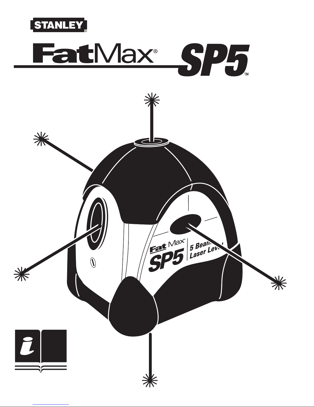
5 BEAM SELF-LEVELING LASER
77-154
INSTRUCTION MANUAL
MANUEL D’INSTRUCTIONS
MANUAL DE INSTRUCCIONES
Page 2
1
2
4
1
3
2
Fig. A
Fig. B
Fig. C
2 • SP5
Page 3

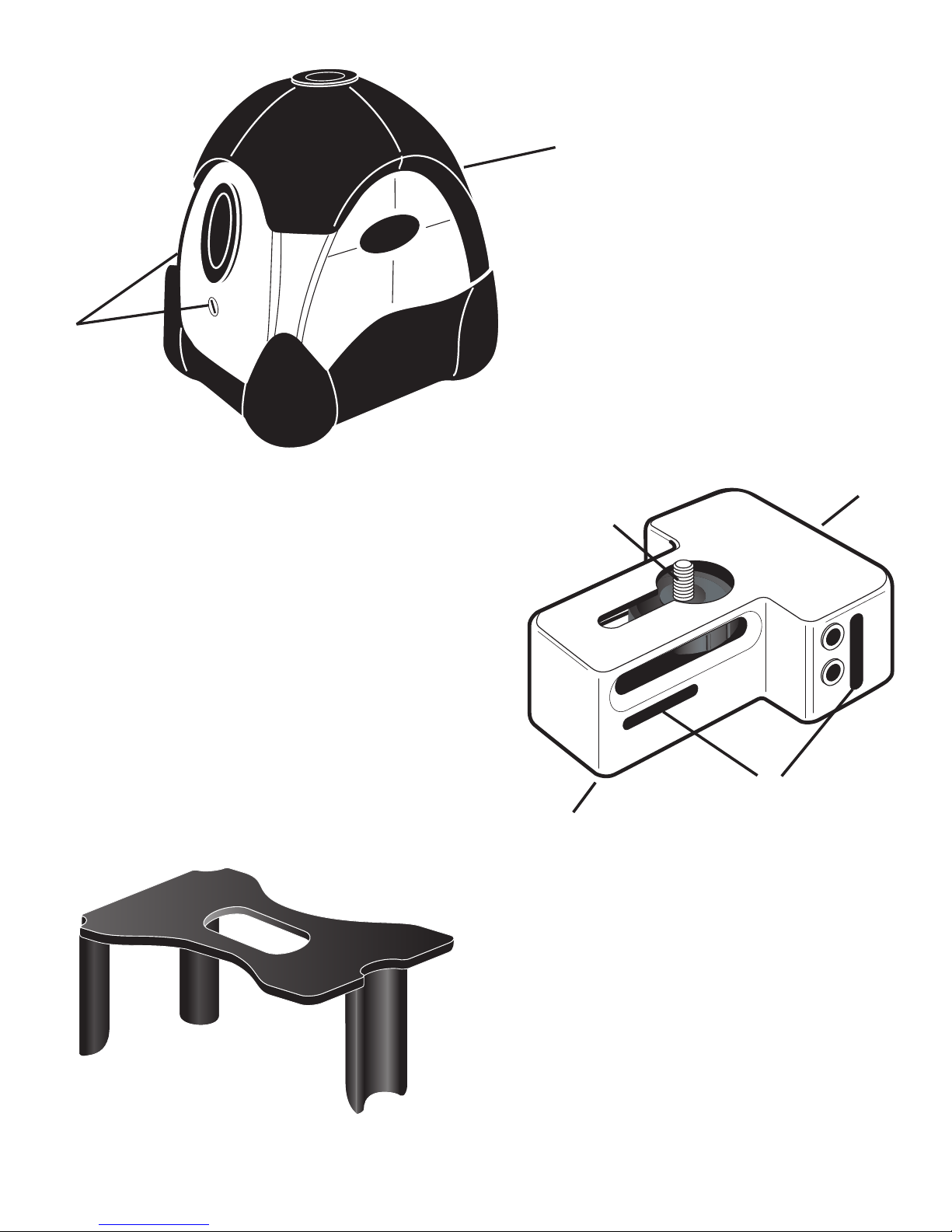
FEATURES (Fig. A)
EN
5 individual laser diodes produce 5 brilliant dots of light
On/Off Switch (#1, Fig. A)
The ON/OFF switch serves two purposes. Not only does it turn the power on
and off, it also locks the lasers in place. When the switch is placed in the
OFF position, a lock mechanism secures the pendulum (laser diodes) for
transportation or storage. This “Push & Slide” mechanism is designed to
protect the pendulum and to provide a product that will last on the job site.
ENGLISH
Out of Level Indicator
The SP5 has a warning to let you know that the unit is out of level beyond its
self-leveling capability. If the lasers start blinking quickly, just move the SP5
to a more level position.
Low Battery Indicator
The laser will blink on and off 4 times every 8 seconds when there is approximately 2 hours of battery life remaining. Average life of the 3 “AA” batteries
is +/- 15 hours of intermittent use. It is always a good idea to put extra batteries in the carrying case.
Two Self Calibration Ports (#2, Fig. A)
ACCESSORIES
Universal Mount (Fig. B)
1. Magnets for attachment to steel objects
2. Slots to attach mounting strap vertically or horizontally
3. 1/4" x 20 or 5/8” x 11 threads for tripod
4. 1/4" x 20 mounting stud for SP5
By sliding the Universal Mount back, you can expose the bottom beam to
transfer down plumb points.
Once the Universal Mount is attached to the bottom of the SP5, the unit can
SP5 • 3
Page 4
be mounted on a 1/4" x 20 thread camera tripod, a 5/8” x 11 surveyor’s tripod
or attached to any ferrous metal surface (such as steel studs) by using the
magnets located on the rear and bottom side of the mount, or fixed thanks to
the strap (supplied) to wood studs, etc.
Trivet – (Fig. C) Platform with 3 legs used for down plumb alignment jobs
(such as framing and drywall installation).
Target – This target is used for enhancing the visibility of the laser dot.
Strap – This strap is used for mounting the universal base to any object 17,80
cm or smaller in diameter, in order to ensure the safety of the instrument, if
mounted on an unstable surface.
Carrying Case – The soft sided carrying case provides ample storage for the
SP5, target, universal mount, laser glasses (not supplied), manual and 1
spare set of batteries (not supplied). The case can be belt mounted or comes
with a carrying strap and handle for easy handling.
APPLICATIONS
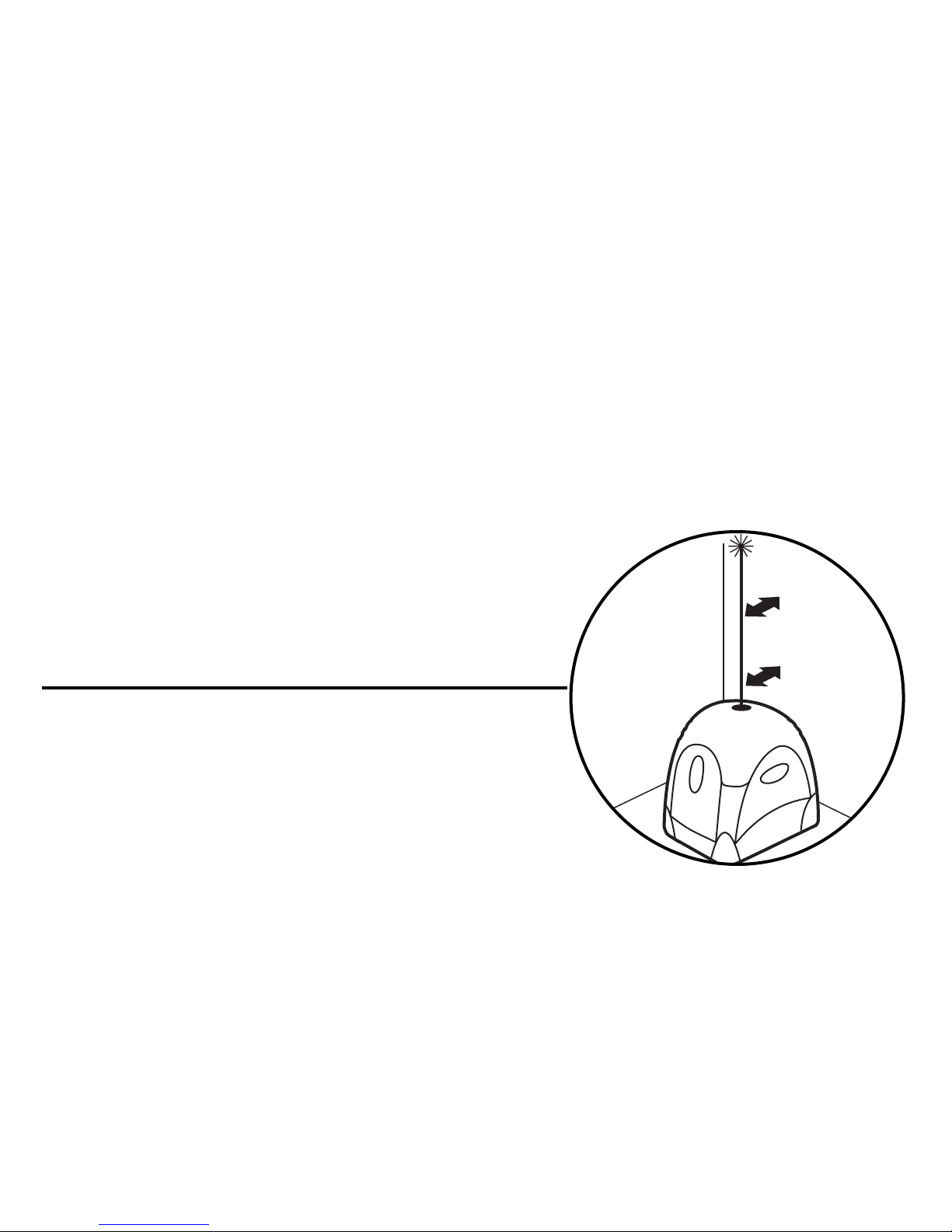
PLUMB (Fig. D)
Fig. D
Place the SP5 on the floor or a fairly level surface near the wall or the object to be plumbed.
Measure from the wall being plumbed to the
laser beam at two points. One point near the SP5
and another point farther away. (Note: the greater
the distance between the two points the greater the possible accuracy).
If the measurements of the two points are the same, then the surface is
plumb. If not, pull the wall in or push it out until the upper and lower measurements are equal.
If you want to transfer a point from the floor to a point on the ceiling or viceversa, mount the SP5 on the universal mount.
Move the SP5 until the point you wish to transfer is centered on the laser
dot. Mark the other point as required.
4 • SP5
Page 5
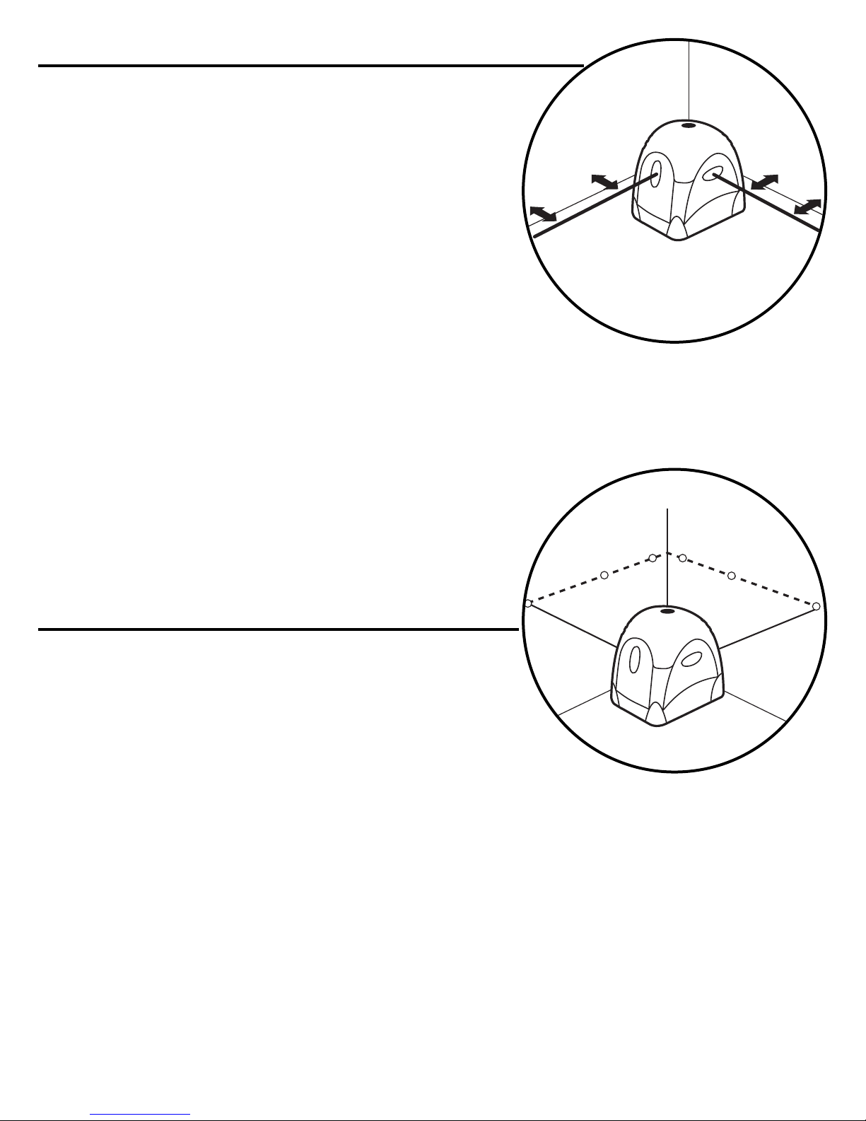
SQUARE (Fig. E)
Place the SP5 on the floor or a fairly level surface near the walls or the objects to be
squared. Measure from one wall to the laser
beam at two points. One point near the SP5
and at another point farther away. (Note: the
greater the distance between the two points
the greater the possible accuracy). Rotate the
Fig. E
SP5 until the two measurements are equal. Do not
move the SP5 until the rest of the measuring is completed. Now take two measurements from the other wall to that laser beam.
If the measurements of these two points are the same, then the walls are
square. If they are not equal, move the second wall until the two measurements are equal.
You can also square vertical surfaces to horizontal
Fig. F
surfaces by using a plumb beam and a level
beam.
LEVEL (Fig. F)
Set the SP5 on a surface that is at a convenient height for marking a level reference plane
on walls or other surfaces. Mark the laser dot’s
location. You can now turn the SP5 to move the
laser dot to another location and continue marking.
These marks can be connected together with a straight edge to give you a
level line.
Be careful not to change the height of the SP5 during the process or your
level line will vary in height.
For damages caused by usage other then intended, the user is responsible.
SP5 • 5
Page 6

INSERTING/REPLACING THE BATTERIES
Remove the Universal Mount if mounted. Remove the battery cover from the
battery compartment located in the bottom of the instrument itself.
Insert the batteries or replace the used batteries with new ones.
Check for correct polarity.
Do not use rechargeable batteries!
Extreme temperatures and the use of batteries with different levels of charge
can reduce the operating time of the instrument.
Always use batteries with the same power rating and from the same manufacturer. For disposal of the used batteries, see the section “Environmental
protection”.
CALIBRATION (Fig. G)
The SP5 is a precision instrument and needs to be handled carefully. If the
SP5 is treated roughly or accidentally dropped, it may need to be re-cal-
ibrated. Check the SP5 on a regular basis, following these steps:
1. Put the SP5 on a stable, smooth surface and turn it on. Aim one of the
side beams (1) at a vertical surface that is at least 20 meters away from
the SP5. Mark the beam’s location on the wall (a).
2. Turn the SP5 180° so the other side beam is now aimed at the original
spot. Mark this new spot (b). If the two spots are at the same height,
then move on to step 4.
3. If the two spots are at different heights, mark a spot half way between
the two (c). Remove the two calibration hole covers by using a screw-
driver. Insert a hex screw (1,5 mm) into the side calibration hole (X) and
turn the adjusting screw until the laser dot is on the new mark you
made (c).
4. Turn the SP5 so that the front beam (2) is pointed at the mark you made.
If the laser dot is not lined up with the mark, insert the adjusting wrench
in the front calibration hole (Y) and turn the adjusting screw until the
laser dot is on the mark you made.
6 • SP5
Page 7

5. Start at step 1 again and re-check your adjustments. If the three laser
dots stay on the same mark, then calibration is complete.
6. Push on the calibration port covers.
Your SP5 is calibrated and ready to go.
SAFETY AND CERTIFICATIONS
Working safely with this instrument is possible only when the operating and
safety information are read completely and the instructions contained therein are strictly followed.
Do not remove the label on the side of the housing.
The use in combination with other optical instruments, manipulations or use
in other applications other than described here, can lead to dangerous laser
outputs.
Do not stare into the laser beam.
Do not direct the laser beam at other persons. Since the laser beam is of the
boundled type, check the beam path over a relatively long distance and take
the necessary precautions.
This laser complies with all applicable portions of title 21 of the Code of
Federal Regulations set by the Dept. of Health, Education, and
Welfare, the Food and Drug Administration, the Center for Devices, and the
Bureau of Radiological Health.
The SP5 has also been tested and complies with the CE certification requirements set forth in the EC regulations 89/336/EEC and EN 61000-6-1 (EN50082-
1), EN 61000-6-3 (EN50081-1) and IEC 60-825-1.
SP5 • 7
Page 8

TECHNICAL DATA
ACCURACY: +/- 6 mm at 30 m
VISIBILITY RANGE: up to 30 m, according to the light conditions
SELF-LEVELING RANGE: +/- 5° in any direction
INDICATING LIGHTS:
Low power: Laser blinks 4x every 8 seconds
Out of level: Laser blinks quickly
POWER: 3 “AA” batteries 1,5 V
LASER OUTPUT: 5 laser diodes, 650 nm.
0.8-1.0 mW each for class 2M;
0.8-2.5 mW for class 3R, each\
LASER CLASS: Class 2M
WEIGHT: 545 g with batteries
UNIVERSAL BASE 200 g
MAINTENANCE AND CARE
The SP5 is not waterproof. Do not allow the unit to get wet. Damage to internal circuits will result.
Do not leave the SP5 out in direct sunlight or expose it to high temperatures.
The housing and some internal parts are made of plastic and may become
deformed at high temperatures.
Do not store the SP5 in a cold environment. Moisture will form on interior
parts when warming up. The moisture could fog up laser windows and cause
corrosion of internal circuit boards.
When working in dusty locations, some dirt will collect on the laser
windows. Remove any moisture or dirt with a soft, dry cloth.
Do not use
aggressive cleaning agents or solvents.
Store the SP5 in its case when not in use. Remove batteries before storage
of the instrument.
8 • SP5
Page 9

ENVIRONMENTAL PROTECTION
Recycle raw materials instead of disposing as waste.
The machine, accessories and packaging should be sorted for environmen-
tal-friendly recycling.
Do not throw used batteries into house waste, fire or water but dispose of in
an environmentally friendly manner according to the applicable legal regulations.
WARRANTY
One Year Warranty. The Stanley Works warrants the SP5 against defects in
material and workmanship for one year from the date of purchase. Deficient
products will be repaired or replaced at Stanley’s discretion. For warranty
repair information, call
(815) 432-5237
CST/berger, a division of STANLEY WORK®
Stanley’s liability under this warranty is limited to repair or replacement of
the unit. Any attempt to repair the product by other than factory authorized
personnel will void this warranty. Calibration, batteries and maintenance are
the responsibility of the user. Where permitted by law, Stanley is not responsible for incidental or consequential damages. Agents of Stanley cannot
change this warranty. Stanley is not responsible for damage resulting from
wear, abuse, or alteration of this product. The user is expected to follow ALL
operating instructions.
This warranty may provide you with additional rights that vary by state,
province or nation.
SP5 • 9
Page 10

CARACTERISTIQUES (Fig. A)
F
Cinq diodes laser séparées créent cinq points très visibles
1. INTERRUPTEUR ON/OFF
Cet interrupteur remplit deux fonctions. Non seulement il permet d’allumer
ou d’éteindre le laser mais il bloque aussi le pendule interne. Lorsque l’interrupteur se trouve en position OFF, un mécanisme bloque le pendule (diodes
laser) pour assurer une protection pendant le transport. Ce mécanisme
“Push & Slide” est conçu pour protéger le pendule et assurer sa durée de
vie sur le chantier.
FRENCH
INDICATION DE HORS-NIVEAU
Lorsque l’instrument est en dehors de son champ d’auto-nivelage, le laser
vous prévient en faisant clignoter rapidement les rayons laser. Dans ce cas
repositionnez le laser plus à niveau.
INDICATION DE BATTERIES A PLAT
Si les rayons laser clignotent quatre fois toutes les huit secondes, vos batteries n’ont plus que 2 heures d’autonomie. La durée moyenne des trois batteries est d’environ 15 heures d’emploi intermittent. C’est une bonne idée
que de mettre dans la mallette un groupe de batteries de rechange grâce à
sa capacité.
2. Accès vis de calibrage.
ACCESSOIRES
Base universelle (Fig. B)
1. Aimants pour fixer l’instrument à des objets métalliques.
2. Fissures pour utiliser la bande de fixage verticalement ou horizontalement.
3. Filets à 1/4”x 20 ou 5/8” x 11 pour trépieds
4. Vis à 1/4" x 20 pour l’SP5
10 • SP5
Page 11

En faisant glisser en arrière l’instrument sur la base, on expose le rayon vertical vers le bas pour mettre à plomb des points.
Quand le laser est monté sur la base, il peut être monté sur les trépieds avec
fixage à 1/4” x 20 ainsi que sur ceux ayant un fixage à 5/8” x 11, ou bien il
peut être fixé à n’importe quelle surface métallique (par exemple des piliers
en acier) grâce aux aimants dont il dispose. En utilisant la bande fournie
dans la mallette on peut le fixer aussi à des tiges en bois ou à d’autres supports non ferreux.
Cible
Cette cible est utilisée pour augmenter la visibilité du rayon.
Laser Plumb Trivet (Fig. C)
Pour déplacer facilement les points d’aplomb du sol au plafond
Bandelette
Cette bandelette est utilisée pour fixer la base à n’importe quel objet au
diamètre jusqu’à 17,80 cm., pour garantir la sûreté de l’instrument quand il
est appuyé sur une surface non stable.
Mallette
Cette mallette de transport a une grande capacité et peut contenir instrument, cible, base universelle, bandelette, manuel, lunettes (non fournies), 1
groupe de batteries de rechange (non fourni). La mallette peut être agrafée à
la ceinture ou elle peut être transportée facilement grâce à un manche ou à
une bandoulière.
SP5 • 11
Page 12

APPLICATIONS
PLOMB (Fig. D)
Placez l’instrument SP5 sur le sol ou sur une surface assez à niveau près de
l’objet qui doit être mis à plomb.
Mesurez la distance entre le rayon laser et la surface à mettre à plomb en
deux points. Un point près de l’SP5 et un autre plus distant (à remarquer :
plus grande est la distance entre les deux points, plus grande est la précision que l’on obtient).
Si les deux mesures sont égales, alors la surface est à plomb.
Autrement, déplacez en avant ou en arrière la surface à mettre à plomb,
jusqu’à ce que les deux mesures soient égales.
Si vous voulez déplacer un point du sol au plafond ou vice versa, placez l’in-
strument sur sa base.
Faites glisser en arrière le laser sur la base jusqu’à ce que le point laser ver-
tical se trouve centré sur le point à déplacer. Marquez l’autre point.
EQUERRES (Fig. E)
Placez l’instrument SP5 sur le sol ou sur une surface assez à niveau près
des deux parois qui doivent être mises en équerre. Mesurez la distance
entre le rayon laser et la paroi en deux points. Un point près de l’SP5 et un
autre plus distant (à remarquer : plus grande est la distance entre les deux
points, plus grande est la précision que l’on obtient).
Tournez légèrement le laser jusqu’à ce que les deux mesures soient égales.
Maintenant ne déplacez plus l’SP5 jusqu’à la fin des mesurages. Maintenant
prenez deux mesures entre l’autre paroi et l’autre rayon laser. Si les mesures
de ces nouveaux points sont égales, alors les deux parois sont à angle droit,
autrement déplacez la deuxième paroi jusqu’à ce que ces deux mesures
soient égales.
Vous pouvez aussi mettre en équerre une surface horizontale avec une verticale, en utilisant l’un des rayons à plomb et l’un des rayons à niveau.
12 • SP5
Page 13

NIVEAUX (Fig. F)
Placez l’SP5 sur une surface à une hauteur commode pour marquer des
points de niveaux sur des parois ou sur d’autres surfaces. Marquez le point.
Maintenant vous pouvez tourner le laser pour déplacer le point laser dans un
autre point et faire une autre marque. Vous pouvez également relier ces
points afin de créer une ligne à niveau. Faites attention à ne pas changer la
hauteur de l’instrument pendant ces mesurages, sinon votre ligne aura une
hauteur différente.
L’usager est responsable d’éventuels dommages causés par des emplois
différents de ceux qui viennent d’être décrits.
MISE EN PLACE/REMPLACEMENT DES PILES
Enlever la base universelle. Enveler le couvercle du boîtier des batteries
situé dans la partie inférieure de l’instrument. Introduire les piles ou remplacer celles qui sont usées par des neuves.
Veiller à les introduire correctement pour respecter la polarité. Ne pas utiliser de piles rechargeables. L’autonomie de fonctionnement de cet appareil
diminue en cas de températures très élevées ou si l’on utilise des piles ayant
des états de charge différents.
Remplacer toujours toutes les piles. Utiliser des piles de la même marque
ayant la même puissance. Pour l’élimination des piles usées, voir le chapitre
‘’Protection de l’environnement’’ .
CONTROLE DE LA PRECISION (Fig. G)
Le laser SP5 est un instrument de précision et doit être manié soigneusement. S’il est manié mal ou si on le fait tomber, il est probable qu’on doive le
recalibrer. Contrôlez l’instrument régulièrement de la façon suivante :
1. Placez l’SP5 sur une surface lisse et stable ; puis allumez-le. Braquez
l’un des rayons latéraux vers une paroi distante au moins de 20 mètres
de l’SP5.
Faites une marque sur la paroi en correspondance du rayon (a).
SP5 • 13
Page 14

2. Tournez le laser de 180° de façon à pouvoir diriger le deuxième rayon
latéral vers le point sur la paroi. Marquez ce nouveau point (b). Si les
deux marques se trouvent à la même hauteur, alors passez au point 4.
3. Si les deux marques se trouvent à des hauteurs différentes, faites une
marque à moitié (c) entre les deux précédentes. Enlevez les couvertures des deux vis de calibrage au moyen d’un tournevis. Insérez une
clé hexagonale à 1,5 mm. dans le trou latéral (X) et tournez la vis
jusqu’à ce que le rayon laser soit centré sur la nouvelle marque que
vous venez de faire (c).
4. Tournez l’SP5 en sorte que le rayon frontal (2) soit centré sur la marque
que vous avez faite. Si le point n’est pas aligné avec la marque, insérez
la clé hexagonale dans le trou frontal (y) et tournez la vis et le rayon
laser n’est pas centré sur la marque que vous avez faite.
5. Répétez les points de 1 à 4 de façon à contrôler les réglages que vous
venez de faire. Si les trois points laser sont centrés sur la même marque, alors le calibrage est achevé.
6. Remettez à leur place les couvertures des vis de calibrage.
SURETE ET CERTIFICATIONS
Avant d’utiliser l’appareil, et pour ne courir aucun risque, lire attentivement
la notice et les consignes de sécurité qui y sont imparties. Respecter toutes
ces consignes. Ne pas détacher l’étiquette apposée sur le côté de l’appareil.
L’emploi avec d’autres instruments optiques, les maniements et les utilisations dans d’autres domaines différents de ceux dont nous avons parlé plus
haut peuvent mener à des émissions potentiellement nuisibles.
Ne pas regarder le rayon.
Ne pas pointer le laser sur d’autres personnes. En raison de la fréquence du
rayon laser, faire également attention au passage du rayon en cas de
longues distances et prendre les précautions qui s’imposent.
14 • SP5
Page 15

Cet instrument satisfait à toutes les normes du # 21 du Code des Règlements
Fédéraux (U.S.A.), du Département de la Santé, Education et Prévoyance, de
l’Administration pour l’Alimentation et les Médicaments, du Centre pour les
Approvisionnements et du Bureau Radiologique de la Santé.
L’instrument est en outre Certifié CE, vu qu’il obtempère aux dispositions
contenues dans les 89/336/EEC et EN 61000-6-1 (EN50082-1),
EN 61000-6-3 (EN50081-1) e IEC 60-825-1.
DONNEES TECHNIQUES
PRECISION DE MISE A NIVEAU: +/- 6 mm à 30 m
VISIBILITE : 30 m selon les conditions de
luminosité ambiante
CHAMP D’AUTO-NIVELAGE: +/-5° dans toutes les directions
INDICATIONS:
Batteries à plat Les rayons clignotent 4 fois
toutes les 8 secondes
Hors-niveau Les rayons clignotent rapidement
ALIMENTATION: 3 piles de 1,5 V LR6
TYPE LASER: 5 diodes laser, 650 nm. 08-1.0 mW
classe II; 0.8-2.5 mW classe IIIA,
CLASSE LASER: 2M
POIDS: 545 g avec batterie
BASE UNIVERSELLE : 200 g
chaque diode
SP5 • 15
Page 16

ENTRETIEN
Le laser SP5 n’est pas étanche. Ne le mouillez pas, vous pourriez endommager les circuits internes. Ne laissez pas l’MPS sous la lumière directe du
soleil et ne l’exposez pas à des températures élevées. La “CHARPENTE” et
quelques parties internes sont en matériel plastique et pourraient se
déformer à de hautes températures. Ne gardez pas le laser dans un milieu
très froid, de la moiteur pourrait se former sur les parties internes quand
ensuite il se réchauffe. La moiteur pourrait embuer les verres de sortie des
rayons et oxyder les fiches électroniques internes.
Quand on travaille dans des milieux poussiéreux, de la poussière et de la
salissure pourraient se déposer sur les fenêtres de sortie des rayons.
Nettoyez toujours l’instrument au moyen d’un drap moelleux et sec, pour
éliminer toute trace d’humidité. N’utilisez ni détergents ni solvants agressifs.
Si vous n’avez pas l’intention d’employer l’instrument pour longtemps, on
vous conseille de le replacer dans sa mallette et d’en ôter les batteries.
PROTECTION DE L’ENVIRONNEMENT
Récupération des matières premières et non pas simple élimination des
déchets.
L’appareil, les accessoires et l’emballage doivent être envoyés dans une
déchetterie servant de centre de recyclage. Ne pas jeter les piles usées
dans les ordures ménagères, dans l’eau ni au feu mais les éliminer conformément à la législation en vigueur dans chaque pays.
16 • SP5
Page 17

GARANTIE
Stanley Works garantit le détecteur SP5 contre les défauts de matériaux et
de main d’œuvre pendant un an à partir de la date d’achat.
(815) 432-5237
CST/berger, a division of STANLEY WORK®
La responsabilité de Stanley sous cette garantie est limitée à la réparation
ou au remplacement de l’unité. Toute tentative de réparation du produit par
une personne autre que le personnel d’usine agréé annulera cette garantie.
L’étalonnage, les piles et l’entretien sont à la charge de l’utilisateur. Où permis par la loi, Stanley ne pourra pas être tenu responsable des dégâts accidentels ou conséquents. Les agents de Stanley ne peuvent pas changer
cette garantie. Stanley ne pourra pas être tenu responsable des dégâts dus
à l’usure, l’abus ou aux modifications de ce produit. L’utilisateur est supposé
suivre TOUTES les instructions de fonctionnement.
Cette garantie peut vous donner d’autres droits variant selon l’état, la
province ou la nation.
SP5 • 17
Page 18

DESCRIPCIÓN (Fig. A)
E
5 diodos láser individuales producen 5 punto de luz brillante
1. INTERRUPTOR ON/OFF
El interruptor ON/OFF ofrece 2 utilidades. Además de encender y apagar el
instrumento, también traba el láser en su sitio. Cuando el interruptor esté en
la posición OFF, un mecanismo bloquea el péndulo (diodos láser) para protegerlo durante el transporte. Este mecanismo « Push & Slide » protege el péndulo y garantiza un producto que dura en la obra.
SPANISH
INDICADOR DE FUERA DE NIVEL
El SP5 posee un indicador que le avisa cuando la unidad esta fuera de su
margen de autonivelado. Si el láser empieza a parpadear rapidamente solo
tiene que mover el SP5 a una posición más nivelada.
INDICADOR DE PILAS AGOTADAS
El láser parpadeará hasta 4 veces cada 8 segundos cuando queden unas 2
horas de bateria. La vida media de 3 pilas “AA” es +/- 15 horas. Es una
buena idea llevar algunas pilas extra en el maletín de transporte, ya que hay
suficiente espacio para ello.
2. Dos puertos de calibración.
ACCESORIOS
Soporte Universal (Fig. B)
1. Imanes para adherirse a objetos metalicos
2. Ranuras para colocar la correa en vertical u horizontal
3. Roscas para tripode 1/4” x 20 o 5/8” x 11
4. Perno de ensamble 1/4” x 20 para el SP5
Deslizando el soporte universal atras, puede trabajar con el rayo inferior
para trasladar hacia abajo punto de plomada.
18 • SP5
Page 19

Una vez colocado en la parte inferior del SP5, la unidad puede montarse en
un tripode de camara con rosca 1/4” x 20, un tripode de topografía con rosca
5/8” x 11 o adherirse a cualquier superficie metalica ferrica (ej. Un poste de
acero) con los imanes o también puede sujetarse a un poste de madera con
la correa.
Diana
La diana sirve para aumentar la visibilidad del punto láser.
Laser Plumb Trivet (Fig. C)
Para trasladar facilmente un punto del suelo en el techo.
Correa
Esta correa se utilizza para sujetar la base universal a cualquier objeto de
hasta 17,80 cm de diámetro.
Muy adecuado para garantizar la securidad del laser, cuando esté colocado
sobre una superficie inestable.
Maletín de transporte
El maletín de transporte proporciona un amplio alamcenaje para el SP5,
diana, soporte universal, correa ajustable, manual de instrucciónes, juego de
pilas de repuesto (non incluido), y gafas (non incluido). El maletín puede
engancharse al cinturón o transportarse fácilmente en bandolera.
SP5 • 19
Page 20

APLICACIONES
PLOMADA (fig. D)
Coloque el SP5 en el suelo o en una superficie bastante nivelada cerca del
objeto a aplomar. Mida desde la superficie aplomandose hasta el rayo láser
en dos puntos. Un punto cerca del SP5 y el otro punto un poco más lejos
(Nota: cuanto mayor sea la distanzia entre los dos puntos, mayor será la
posible exactitud).
Si las mediciones de los dos puntos son iguales, entonces la superficie está
aplomada.
Si no, acerque o aleje el tabique hasta que la medición superior e inferior
sean iguales.
Si quiere trasladar un punto desde el suelo hasta un punto en el techo o
viceversa, coloque el SP5 en el soporte universal. Mueva el SP5 hasta que el
punto que desea trasladar esté centrado en el punto láser. Marque el otro
punto según lo requerido.
ESCUADRA (Fig. E)
Coloque el SP5 en el suelo o en una superficie bastante nivelada cerca de
los objetos a escuadrar. Mida desde una superficie hasta el rayo láser en
dos puntos. Un punto cerca del SP5 y el otro punto un poco más lejos (Nota:
cuanto mayor sea la distanzia entre los dos puntos, mayor será la posible
exactitud). Gire el SP5 hasta que las dos medidas sean iguales. No mueva el
SP5 hasta que el resto de mediciones se hayan realizado. Entonces, tome
dos medidas desde la otra superficie hasta el rayo láser. Si las mediciones
de ambos puntos coinciden, entonces la superficie está en escuadra. Si no
son iguales, mueva la superficie hasta que las dos mediciones coincidan.
También puede sacar escuadras verticales en superficies horizontales con
la ayuda de una plomada y un nivel de burbuja.
20 • SP5
Page 21

NIVEL (fig. F)
Situe el SP5 en una superficie que está a una altura suficiente para marcar
el nivel de referencia en paredes u otras superficies. Marque la situación de
los puntos láser. También puede girar el SP5 para mover el punto láser hasta
otra situación y continuar marcando. Estas marcas pueden unirse con una
linea recta para darle así la linea de nivel.
Atención! No cambie la altura del SP5 durante este proceso o su linea de
nivel variará en altura.
El usuario es responsable de los posibles daños ocasionados, derivados de
un uso incorrecto.
INSERCIÓN/ CAMBIO DE LAS PILAS
Desmontar el soporte universal. Retirar la tapa del alojamiento de las pilas,
que se encuentra en la parte inferior del laser. Introducir las pilas o bien
sustituir las gastadas por pilas nuevas.
Ponga atención al introducir las pilas según la adecuada polarización.
No utilizar pilas recargables.
La autonomía del instrumento se reduce en caso de temperaturas extremas
o bien utilizando pilas con distintos estados de carga.
Cambiar regularmente todas las pilas. Utilizar pilas de un solo fabricante y
que tengan la misma capacidad.
Para el correcto aprovechamiento de las pilas gastadas, ver el apartado
“Medidas ecológicas”.
SP5 • 21
Page 22

CALIBRACIÓN (Fig. G)
El SP5 es un instrumento de precisión y necesita ser tratado con cuidado. Si
se trata rudamente o cae accidentalmente, puede ser necessario volver a
calibrarlo. Cuando sea necessario, la calibración es fácil de comprobar y
corregir.
1. Situe el SP5 en una superficie suave y estable y enciendalo. Dirija uno
de los rayos laterales (1) hacia una superficie vertical situada a 20 m
del SP5. Marque la situación del rayo en la pared (a).
2. Gire el SP5 180° de manera que el otro rayo lateral esté dirigido hacia el
punto original. Marque este nuevo punto (b). Si los dos puntos están a
la misma altura, pase al paso 4.
3. Si los dos puntos están a distintas alturas, marque un punto a mitad de
ambos (c). Quite la tapa de los dos agujeros de calibración, utilizando
un destornillador. Utilizando una llave hexagonal (1,5 mm) entre en el
agujero de calibración lateral (X) y gire el tornillo de ajuste hasta que el
punto láser esté en la nueva marca que Usted ha hecho (c).
4. Gire el SP5 de manera que el rayo frontal (2) esté dirigido hacia la
marca que Usted ha hecho. Si el punto laser no está alineado con la
marca, introduzca la llave hexagonal en al agujero frontal (Y) y gire el
tornillo hasta que el punto láser esté en la marca que Usted ha haecho.
5. Empiece de nuevo en el punto 1 y vuelva a comprobar sus ajustes. Si
los tres puntos láser permacenen en la misma marca, entonces se ha
completado la calibración.
6. Ponga las tapas en los puertos de calibración.
Su SP5 está calibrado y listo de nuevo para ser usado.
22 • SP5
Page 23

SEGURIDAD Y ESPECIFICACIONES
Es posible trabajar con el aparato sin peligro, solo después de haber leído
atentamente las instrucciones para el uso y las advertencias de seguridad y
siguiendo estrictamente las instrucciones. No despegar la etiqueta del lateral del aparato.
El uso de instrumentos opticos, controles, ajustes o procedimientos de funcionamiento distintos a los especificados en el presente manual pueden
provocar una exposicion a radiacion peligrosa.
No mirar hacia el rayo.
No apuntar el rayo láser hacia otras personas. A causa de la frecuencia del
rayo láser, prestar atención también al paso del rayo en caso de distancias
largas y tomar las precauciones necesarias.
El equipo cumple con todas las especificaciones del artículo 21 del Código
de Regulación Federal (U.S.A.) del Departamento de Sanidad, Educación,
Alimentacin y del Centro para la Salud Radiológica.
El instrumento también cumple con las especificaciones CE según las normas 89/336/EEC, EN 61000-6-1 (EN50082-1), EN 61000-6-3 (EN50081-1) y IEC
60-825-1.
SP5 • 23
Page 24

DATOS TÉCNICOS
PRECISIÓN: +/- 6 mm a 30 m
VISIBILIDAD: hasta 30 m dependiendo de las
MARGEN DE AUTONIVELADO: +/-5° in todas las direcciones
LUCES INDICADORAS:
Poca bateria El láser parpadea 4 veces cada
Fuera de nivel El láser parpadea rapidamente
ALIMENTACIÓN: 3 pilas « AA » de 1,5 V LR6
condiciones de luminosidad ambiental
8 segundos
SALIDA LÁSER: 5 diodos, 650 nm. 0.8-1.0 mW cada uno
para Clase 2M, 0.8-2.5 mW para Clase 3R
PESO : 545 g incluyendo pilas
SOPORTE UNIVERSAL: 200 g
MANTENIMIENTO Y CONSERVACIÓN
El SP5 no es a prueba de agua. No permita que el SP5 coja humedad, ya que
se perjudicarian los circuitos internos.
No deje el SP5 fuera bajo la luz del sol directa o expuesto a altas temperaturas. La carcassa y algunas partes internas están fabricadas en plastico y
pueden deformarse a altas temperaturas.
No guarde su SP5 en un lugar frio. Al calentarse puede salir vapor de las
partes internas y entelar la ventana láser y causar corrosión en los circuitos
internos.
Cuando trabaje en sitios de mucho polvo, se pegara suciedad en las ventanas láser. Nunca rasque la suciedad, retirela con un trapo limpio y suave.
Si necesita limpiar más a fondo, utilice alcohol y una bola del algodon.
24 • SP5
Page 25

Guarde el SP5 en su maletín cuando no vaya a usarlo.
Controlar el estado de las baterías regularmente. En caso de no utilizar el
aparato durante un largo período, se aconseja quitar las pilas.
MEDIDAS ECOLÓGICAS
Recuperación de materias primas en lugar de producir desperdicios.
Aparato, accesorios y embalaje deberían someterse a un proceso
de reciclaje. No tirar las pilas gastadas entre los desperdicios domésticos o
al fuego o al agua; eliminarlas de manera ecológica de acuerdo a las directrices legales.
GARANTÍA
Garantía de 1 año
La Stanley Works garantiza el SP5 contra defectos en material y mano de
obra durante un año a partir de la fecha de la compra.
(815) 432-5237
CST/berger, a division of STANLEY WORK®
La responsabilidad de Stanley bajo esta garantía está limitada a la
reparación o al reemplazo de la unidad. Cualquier intento de reparar este
producto por persona diferente al personal autorizado por la fábrica anulará
esta garantía. La calibración, las baterías y el mantenimiento son la responsabilidad del usuario. Donde sea permitido por la ley, Stanley no es responsable por daños incidentales o consecuentes. Los agentes de Stanley no
pueden cambiar esta garantía. Stanley no es responsable por daños como
resultado de desgaste, abuso o alteración de este producto. El usuario está
supuesto a seguir TODAS las instrucciones de operación.
Esta garantía podrá darle derechos adicionales los cuales varían de acuerdo
al estado, la provincia o la nación.
SP5 • 25
Page 26

Fig. D
Fig. E
Fig. F
26 • SP5
Fig. G
Page 27

SP5 • 27
Page 28

480 Myrtle Street, New Britain, CT 06053 U.S.A.
Z94-77154N (0804)
28 • SP5
©2004 THE STANLEY WORKS:
Stanley Tools Product Group,
Tel 1-800-262-2161 Fax 860-643-3756
www.stanleyworks.com
 Loading...