

Page 1
Catalog Number
FME700
INSTRUCTIVO DE OPERACIÓN, CENTROS DE SERVICIO Y PÓLIZA DE GARANTÍA.
ADVERTENCIA: LÉASE ESTE INSTRUCTIVO ANTES DE USAR EL PRODUCTO.
SAVE THIS INSTRUCTION MANUAL FOR FUTURE REFERENCE.
VEA EL ESPAÑOL EN LA CONTRAPORTADA.
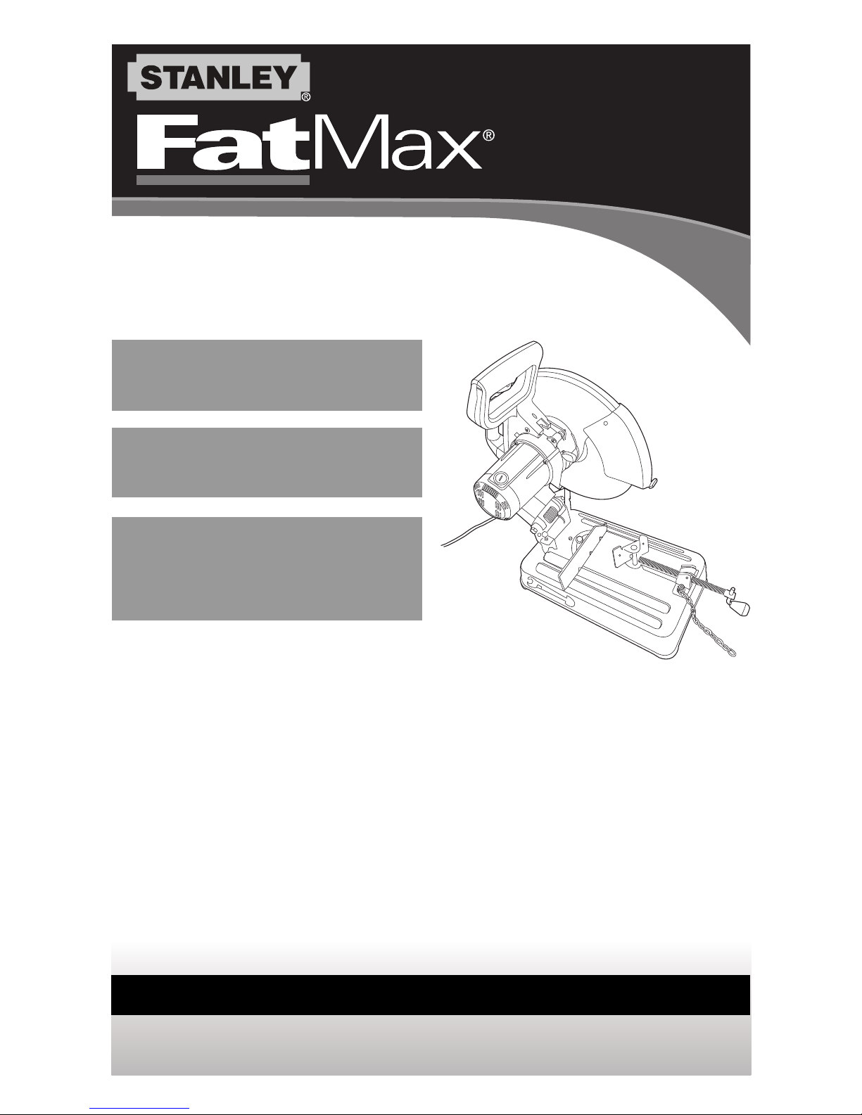
INSTRUCTION MANUAL
14 Inch (355mm)
Chop Saw
Scie fendeuse de
355 mm (14 po)
Serra Multi-Corte de
Metais de 14 pulg.
(355mm)
Page 2

2
GENERAL SAFETY RULES
WARNING: Read all safety warnings and all instructions. Failure to follow the warnings
and instructions may result in electric shock, fire and/or serious injury.
SAVEALLWARNINGSAND INSTRUCTIONS FOR FUTURE REFERENCE
The term “power tool” in the warnings refers to your mains-operated (corded) power tool or
battery-operated (cordless) power tool.
1)WORKAREA SAFETY
• Keep work areaclean and well lit.Cluttered or dark areas invite accidents.
• Donotoperatepowertoolsinexplosiveatmospheres,suchasinthepresenceofflammableliquids,
gasesordust.Power tools create sparks which may ignite the dust or fumes.
• Keep children and bystanders away while operating a power tool. Distractions can cause
you to lose control.
2)ELECTRICAL SAFETY
a)Power tool plugs must matchthe outlet. Never modifythe plugin any way. Donot use
any adapter plugs with earthed (grounded)power tools. Unmodified plugs and matching
outlets will reduce risk of electric shock.
b)Avoidbodycontact with earthedorgrounded surfaces suchaspipes,radiators,ranges and
refrigerators.There isan increased risk of electricshockifyour bodyisearthedorgrounded.
c)Do not expose power tools to rain or wet conditions. Water entering a power tool will
increase the risk of electric shock.
d)Do not abuse the cord. Never use the cord for carrying, pulling or unplugging the
power tool. Keep cord away from heat,oil,sharp edges or moving parts. Damaged or
entangled cords increase the risk of electric shock.
e)When operating a power tool outdoors, use an extension cord suitable for outdoor use.
Useofa cord suitable foroutdoor use reduces the risk of electric shock.
f)If operating a power tool in a damp location is unavoidable, use a groundfault circuit
interrupter (GFCI)protected supply. Use of a GFCI reduces the risk of electric shock.
3)PERSONAL SAFETY
a)Stay alert, watch what you are doing and use common sense when operating a power
tool. Donot use a power toolwhile you are tired or under the influence of drugs,alcohol
ormedication. A moment of inattention while operating power tools may result in serious
personal injury.
b)Use personal protective equipment. Always wear eye protection. Protective equipment
such as dust mask, nonskid safety shoes, hard hat, or hearing protection used for appropriate
conditions will reduce personal injuries.
c)Prevent unintentional starting. Ensurethe switchisin the offpositionbefore connecting to
powersource and/orbatterypack,picking up or carryingthe tool. Carrying power tools withyour
fingeronthe switch orenergizing power tools that have the switchoninvitesaccidents.
d)Remove any adjusting key or wrench before turning the power tool on. A wrenchora key
left attached to arotatingpart of thepower tool may resultinpersonalinjury.
e)Do not overreach.Keep proper footing and balance at all times.This enables better
control of the power tool in unexpected situations.
f)Dress properly. Do notwear loose clothing or jewelry. Keep your hair, clothingand
SAFETY GUIDELINES - DEFINITIONS
It is important for you to read and understand this manual. The information it
contains relates to protecting YOUR SAFETY and PREVENTING PROBLEMS. The
symbols below are used to help you recognize this information.
DANGER: Indicates an imminently hazardous situation which, if not avoided,
will result in death or serious injury.
WARNING: Indicates a potentially hazardous situation which, if not avoided,
could result in death or serious injury.
CAUTION: Indicates a potentially hazardous situation which, if not avoided,
may result in minor or moderate injury.
NOTICE: Used without the safety alert symbol indicates potentially hazardous
situation which, if not avoided, may result in property damage.
Page 3

3
glovesaway from moving parts.Loose clothes, jewelry or longhair can be caught in movingparts.
g)If devices are providedfor the connection of dust extraction and collection facilities,
ensure these are connected andproperly used. Use of dust collection can reduce dust-
related hazards.
4)POWERTOOL USE AND CARE
a)Do not force thepower tool. Usethe correct power tool for your application. The correct
powertoolwill do the job better and safer at the rateforwhichitwas designed.
b)Do not use the power tool if the switch does not turn it on and off. Any power tool that
cannot be controlled with the switch is dangerous and must be repaired.
c)Disconnect the plug from the power source and/or the battery pack fromthe power
tool before making any adjustments,changing accessories, or storing power tools.Such
preventive safety measures reduce the risk of starting the power tool accidentally.
d)Store idle power tools out of the reach of children and do not allow persons unfamiliar
with the power tool or these instructions to operate the powertool. Power tools are
dangerous in the hands of untrained users.
e)Maintainpower tools.Checkfor misalignment or binding ofmoving parts,breakageof parts
andanyother condition thatmayaffect thepower tool’s operation. Ifdamaged,have the
power toolrepairedbeforeuse. Many accidents arecaused by poorly maintained power tools.
f)Keep cutting tools sharp and clean.Properly maintained cutting tools with sharp cutting
edges are less likely to bind and are easier to control.
g)Use thepowertool,accessories andtoolbits,etc.inaccordancewith theseinstructions,
takinginto account the working conditionsandthe work to be performed. Useofthe power tool
for operationsdifferent fromthoseintended could result in a hazardous situation.
5)SERVICE
a)Haveyourpower tool serviced by a qualified repair personusingonly identicalreplacement
parts.This will ensure that the safety ofthe powertoolismaintained.
Additional Safety Rules for Chop Saws
• Always wear proper eye and respiratory protection.
• Before using, inspect the cutting wheel for cracks or flaws. If such a crack or
flaw is evident, discard the wheel. The wheel should also be inspected whenever
you think the tool may have been dropped. Flaws may cause wheel breakage.
• When starting the tool with a new or replacement wheel or if you are unsure of
the condition of the wheel, hold the tool in a well protected area and let it run for
one minute. If the wheel has an undetected crack or flaw, it should burst in less than one
minute. Never start the tool with a person in line with the wheel. This includes the operator.
• In operation, avoid bouncing the wheel or giving it rough treatment. If this occurs,
stop the tool and inspect the wheel for cracks or flaws.
• Clean your chop saw periodically following the procedure in this manual.
• Do not remove wheel guards or base.
• ALWAYS USE THE VISE OR SPECIAL FIXTURE TO CLAMP WORK SECURELY.
Other aids such as spring, bar, or C-clamps may be appropriate for certain sizes and
shapes of workpiece. Use care in selecting and placing these clamps and make a dry
run before making a cut.
• Use only 14 in. (355mm) type 1 wheels rated at 4300 rpm or higher.
• Allow cut off parts to cool before handling.
• Do not attempt to cut wood or plastic with this tool.
• NEVER CUT MAGNESIUM WITH THIS TOOL.
• Use chop saw in a well-ventilated area.
• Turn chop saw off before removing any pieces from the base.
• DO NOT CUT ELECTRICALLY LIVE MATERIAL.
• Do not use circular saw blades or any other toothed blades with this tool.
Serious injury may result.
• DO NOT OPERATE THIS TOOL NEAR FLAMMABLE
LIQUIDS, GASES OR DUST. Sparks or hot chips from cutting or arcing motor
brushes may ignite combustible materials.
• Do not use the side of the abrasive wheel as a deburring grinder. This will substantially
weaken the wheel creating an unsafe condition. The wheel may come apart.
Page 4

4
CAUTION: Wear appropriate hearing protection during use. Under some
conditions and duration of use, noise from this product may contribute to hearing loss.
CAUTION: Spark deflector will get hot.Avoid touching or adjusting while hot. Keep
cordset and materials away from spark deflector.
WARNING: Some dust created by power sanding, sawing, grinding, drilling, and
other construction activities contains chemicals known to the State of California to cause
cancer, birth defects, or other reproductive harm. Some examples of these chemicals are:
• lead from lead-based paints,
• crystalline silica from bricks and cement and other masonry products, and
• arsenic and chromium from chemically-treated lumber (CCA).
Your risk from these exposures varies, depending on how often you do this type of work.
To reduce your exposure to these chemicals: work in a well ventilated area, and work with
approved safety equipment, such as those dust masks that are specially designed to filter
out microscopic particles.
• Avoid prolonged contact with dust from power sanding, sawing, grinding,
drilling, and other construction activities. Wear protective clothing and wash
exposed areas with soap and water. Allowing dust to get into your mouth, eyes, or
lay on the skin may promote absorption of harmful chemicals.
WARNING: Use of this tool can generate and/or disburse dust, which may cause
serious and permanent respiratory or other injury. Always use NIOSH/OSHA approved
respiratory protection appropriate for the dust exposure. Direct particles away from face
and body.
WARNING: Always use NIOSH/OSHA approved respiratory protection appropriate for
the dust exposure. Direct particles away from face and body.
For your convenience and safety, the following warnings are on your Heavy-Duty 14 inch
(355mm) Chop Saw:
WARNING: FOR SAFE OPERATION READ THE INSTRUCTION MANUAL.
• DO NOT USE TOOTHED BLADES.
• USE ONLY REINFORCED WHEELS RATED 4300 RPM OR HIGHER.
• WHEN SERVICING USE ONLY IDENTICAL REPLACEMENT PARTS.
• ALWAYS: WEAR EYE PROTECTION, USE GUARDS, CLAMP WORK IN VISE, USE
PROPER RESPIRATORY PROTECTION.
• DO NOT EXPOSE TO RAIN OR USE IN DAMP LOCATIONS.
• An extension cord must have adequate wire size (AWG or American Wire Gauge)
for safety. The smaller the gauge number of the wire, the greater the capacity of the
cable, that is 16 gauge has more capacity than 18 gauge. An undersized cord will cause
a drop in line voltage resulting in loss of power and overheating. When using more than
one extension to make up the total length, be sure each individual extension contains at
least the minimum wire size. The following table shows the correct size to use
depending on cord length and nameplate ampere rating. If in doubt, use the next
heavier gauge. The smaller the gauge number, the heavier the cord.
Minimum Gauge for Cord Sets
Volts Total Length of Cord in Feet
120V 0-25 26-50 51-100 101-150
(0-7,6m) (7,6-15,2m) (15,2-30,4m) (30,4-45,7m)
240V 0-50 51-100 101-200 201-300
(0-15,2m) (15,2-30,4m)(30,4-60,9m) (60,9-91,4m)
Ampere Rating
More Not more American Wire Gage
Than Than
0-6 18 16 16 14
6-10 18 16 14 12
10 - 12 16 16 14 12
12 - 16 14 12 Not Recommended
Page 5
The label on your tool may include the following symbols. The symbols and their
definitions are as follows:
V..................volts A ..................amperes
Hz................hertz W..................watts
min ..............minutes ................alternating current
..........direct current
n
o ................no load speed
................Class I Construction ..................earthing terminal
(grounded) ................safety alert symbol
................Class II Construction .../min or rpm..revolutions or reciprocation
(double insulated) per minute
POWER SUPPLY
Be sure your power supply agrees with the nameplate marking. A voltage decrease
of more than 10% will cause a loss of power and overheating.
CUTTING CAPACITY
The wide vise opening and high pivot point provide cutting capacity for many large pieces.
Use the cutting capacity chart to determine total maximum size of cuts that can be made
with a new wheel.
CAUTION: CERTAIN LARGE, CIRCULAR OR IRREGULARLY SHAPED
OBJECTS MAY REQUIRE ADDITIONAL HOLDING MEANS IF THEY CANNOT BE
HELD SECURELY IN VISE.
CAUTION: DO NOT CUT MAGNESIUM WITH THIS TOOL.
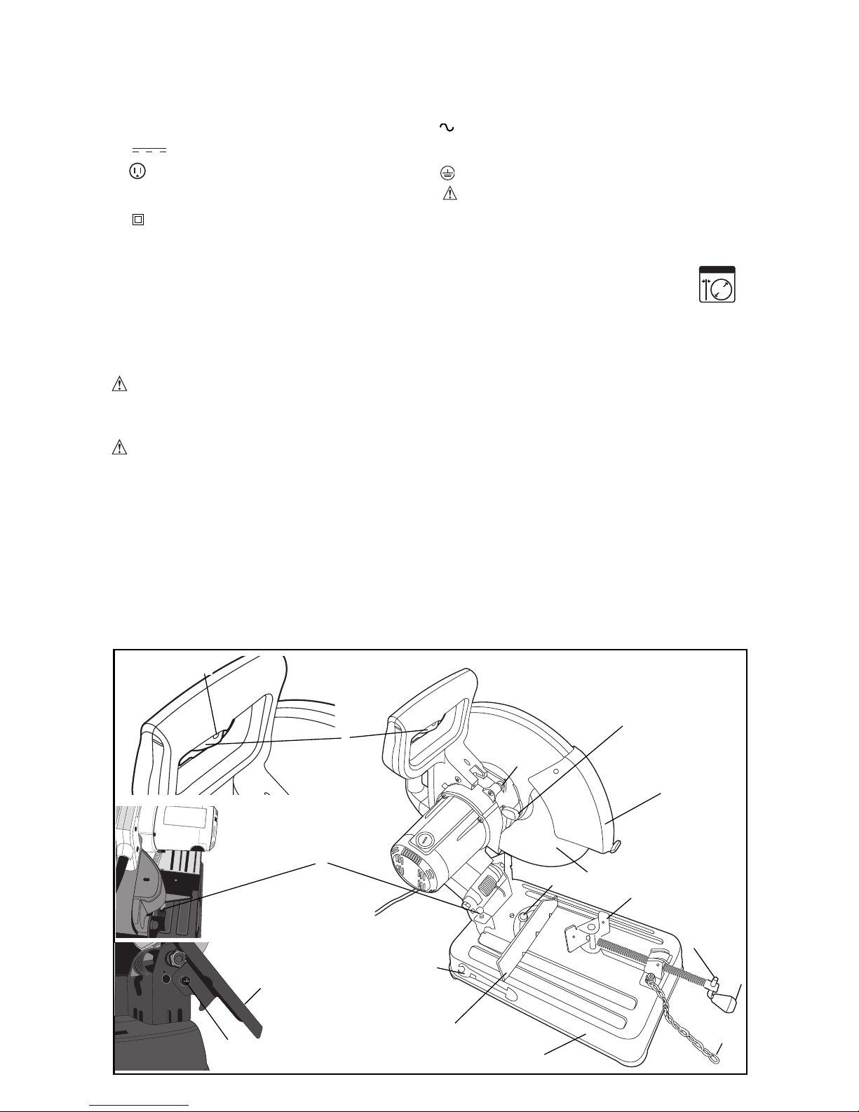
FEATURES
(FIGURES 1, 4)
A. Lock Chain
B. Spark deflector screw
C. Spark deflector
D. Base
E. Fence
F. Vise
G. Flat Wrench
H. Crank
I. Vise Lever
J. Wheel
K. Guard
L. Spindle Lock
M. Depth Stop Bolt and
Jam Nut
N. Trigger Switch
O. Padlock Hole
P. Fence Bolts
Q. Chain Hook
5
2.8
3
55
MAX. mm
Fig. 1
D
E
F
G
H
B
L
K
I
A
N
M
C
O
J
P
Q
Page 6
6
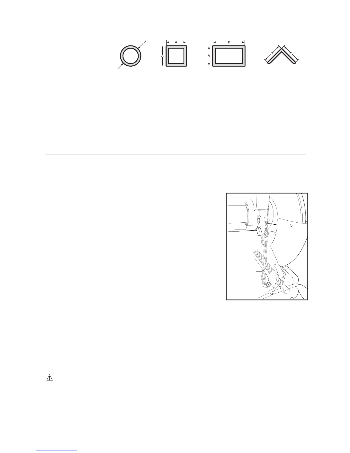
MAXIMUM CUTTING CAPACITY
NOTE: Capacity shown on chart assumes no wheel wear and optimum fence position.
Workpiece Shape:
A X B
90° CuttingAngle A= 4-7/8 in A= 4-1/2 in 4 1/2 in x 51/8in A= 4 1/2in x 5 3/8 in
(125mm) (115mm) (115mm x 130mm) (115mmx 137mm)
4 in x 7-5/8 in
(102mm x 188mm)
3 in x 7-3/8 in
(76mm x 229mm)
45° CuttingAngle A= 4-1/2 in A = 3-13/16 in 4 1/2 in x 313/16 in A= 3-13/16 in
(115mm) (98mm) 4 1/8 in x 33/4in 3-3/4 in
( 105mm x 95mm) (95mm)
STANDARD EQUIPMENT
1 14 inch (355mm) Metal Cutting Abrasive Wheel
1 Wheel Wrench
1 Instruction manual
TO CARRY (FIG. 1a)
Fold down unit to position where you can carry the saw. Hook
lock chain (A) to chain hook (Q).
UNLOCKING (FIG. 1a)
To unlock tool and raise head, depress motor arm slightly and
unhook lock chain (A) from chain hook (Q). Motor arm will
then pivot upward.
SPARK DEFLECTOR ADJUSTMENT (FIG. 1)
To best deflect sparks away from surrounding persons and materials, loosen the screw (B),
adjust the spark deflector (C) and then retighten screw. Do not allow cordset to come into
contact with deflector or sparks as damage to cordset may occur.
DEPTH STOP (FIG. 1)
Depth stop is set at the factory for a new 14 inch (355mm) wheel to prevent wheel from
cutting into the supporting surface. To allow more depth of cut, use the flat wrench provided
(G) to loosen the depth stop bolt (M) and lower bolt to desired height and then turn jam nut
(M)clockwise until seated firmly on the casting. Securely tighten the depth stopbolt beforeuse.
CAUTION: When changing to a new wheel, readjust depth stop to original position to
prevent cutting into supporting surface.
TRIGGER SWITCH (FIG. 1)
To start the tool, depress the trigger switch (N). To turn the tool off, release the trigger
switch. Keep hands and material from wheel until it has coasted to a stop.
To prevent unauthorized use of tool, install a standard padlock (not included) into the
padlock hole (O) located in the trigger.
Fig. 1a
A
Q
Page 7
7
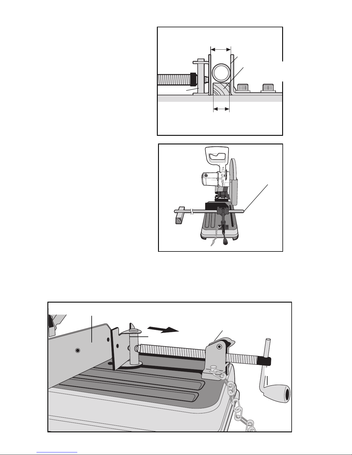
MATERIAL CLAMPING AND SUPPORTING (FIG. 2, 3)
• Angled material is best clamped and
cut with both legs resting against
base.
• A spacer block slightly narrower than
the workpiece can be used to
increase wheel utilization (Fig. 2).
• Long workpieces must be supported
by a block so it will be level with top
of base (Fig. 3). The cut off end
should be free to fall downward to
avoid wheel binding.
VISE OPERATION (FIG. 4)
The vise (F) has a quick-travel feature. To release the vise when it is clamped tightly, turn
the crank (H) counterclockwise one or two times to remove clamping pressure. Lift vise
lever (I) up. Pull crank assembly out as far as desired. Vise may be pushed forward into
work without cranking. Lower vise lever (I) then tighten vise (F) on work by using crank (H).
Fig. 2
WIDTH OF SPACER BLOCK
LARGEUR DE LA CALE DʼÉCARTEMENT
ANCHO DEL BLOQUE ESPACIADOR
DIAMETER OF WORKPIECE
DIAMÈTRE DE LA PIÈCE DE TRAVAIL
DIÁMETRO DE LA PIEZA DE TRABAJO
F
E
SPACER BLOCK
CALE DʼÉCARTEMENT
BLOQUE ESPACIADOR
Fig. 3
CUT-OFF END
EXTRÉMITÉ
COUPÉE
EXTREMO A
CORTAR
BLOCK
BLOC
BLOQUE
Fig. 4
H
I
F
E
FORWARD
MARCHE AVANT
HACIA ADELANTE
Page 8

8
FENCE OPERATION (FIG. 5, 6)
CAUTION: To reduce the risk of injury,
turn unit off and disconnect machine from
power source before installing and removing
accessories, before adjusting or changing
set-ups or when making repairs. Be sure the
trigger switch is in the OFF position. An
accidental start-up can cause injury.
The fence (E) can be adjusted two ways: to
change desired cutting angle and to change
spacing between the fence and vise.
TO CHANGE THE DESIRED CUTTING
ANGLE
Use the wrench provided to loosen (do not
remove) the two fence bolts (P). Align the
desired angle indicator line with the slot line
(Q) in the base (D). Securely tighten both
fence bolts before use. For more accurate
square cuts, disconnect the power supply,
loosen the two fence bolts, push arm down
until wheel extends into base. Place a square
against the wheel and adjust fence against
the square. Securely tighten both fence bolts
before use. When making a miter cut, the
vise (F) may not clamp securely, depending
on the thickness of the workpiece and the
miter angle. Other aids (such as spring, bar
or C-clamps) will be necessary to secure the
workpiece to the fence when making these
cuts.
TO CHANGE SPACING BETWEEN THE FENCE AND VISE
Using the wrench provided, loosen and remove the two fence bolts (P). Adjust the fence
(E) to desired locations. Insert both fence bolts in provided locations. Securely tighten both
fence bolts before use.
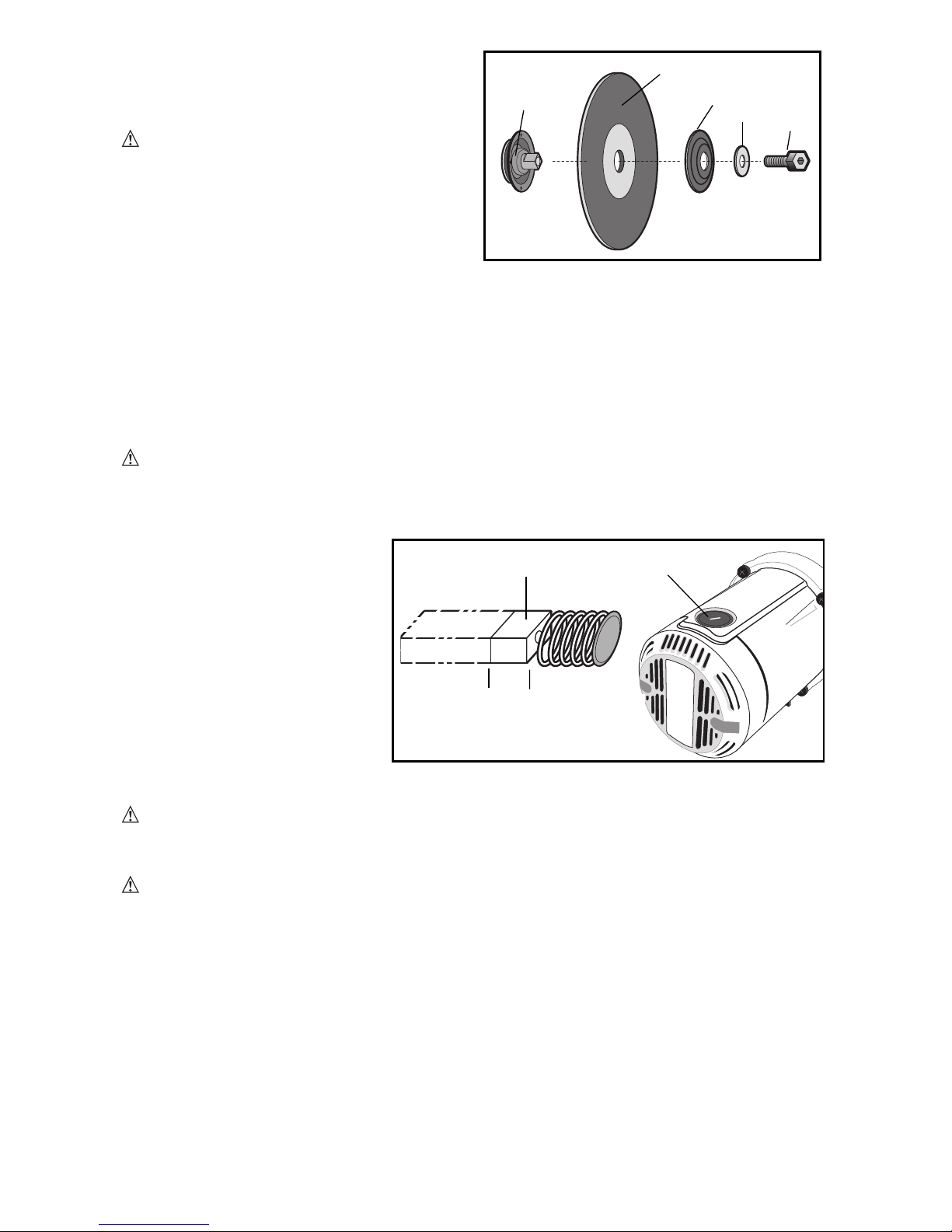
REMOVAL AND INSTALLATION OF WHEELS (FIG. 7, 8)
CAUTION: Turn off and unplug the tool
before making any adjustments or removing
or installing attachments or accessories. Be
sure the trigger switch is in the OFF
position. Do not make any adjustment while
the wheel is in motion.
Do not make any adjustment while chop saw is
plugged into power supply.
1. Push in wheel lock lever (L) and rotate
wheel (J) by hand until wheel lock lever
engages slot in inside flange (R) to lock
wheel. Loosen the bolt (S) counterclockwise
in the center of the abrasive wheel with the
included flat wrench (G). Bolt has right-hand
thread.
2. Remove the bolt (S), washer (T), outside
flange (U) and old wheel (J).
Fig. 6
Fig. 5
P
F
E
Q
D
Q
E
P
Fig. 7
L
Page 9
9
3. Make sure flange surfaces are clean and
flat. Install the new abrasive wheel by
reversing the above steps.
4. Do not overtighten bolt.
WARNING: Risk of personal injury.
Check the work surface that the chop saw
rests on when replacing with a new abrasive
wheel. It is possible that the wheel may
contact ANY ITEMS OR STRUCTURE THAT
EXTENDS ABOVE work surface (under the
base) when the arm is fully lowered.
OPERATION TIPS FOR MORE ACCURATE CUTS
• Allow the wheel to do the cutting. Excessive force will cause the wheel to glaze reducing
cutting efficiency and/or to deflect causing inaccurate cuts.
• Properly adjust fence angle.
• Make sure material is laying flat across base.
• Properly clamp material to avoid movement and vibration.
MAINTENANCE
MOTOR BRUSH INSPECTION AND REPLACEMENT (FIG. 9)
WARNING: To reduce the risk of injury, turn unit off and disconnect machine
from power source before installing and removing accessories, before adjusting or
changing set-ups or when making repairs. Be sure the trigger switch is in the OFF
position. An accidental start-up can cause injury.
Brushes should be regularly
inspected for wear. To inspect
brushes, remove brush cap (W).
Brushes (V) should slide freely in
brush box. If brushes are worn
down to .3 inch (8mm) as
shown in Figure 9 they should be
replaced. To reinstall, push new
brush back into brush
box. If replacing existing brush,
maintain same orientation as
when removed. Replace the
brush cap (do not overtighten).
CLEANING
WARNING: Blow dirt and dust out of the main housing with dry air as often as dirt
is seen collecting in and around the air vents. WearANSI Z87.1 (CAN/CSAZ94.3)
approved eye protection when performing this procedure.
CAUTION: When cleaning, use only mild soap and a damp cloth on plastic parts.
Many household cleaners contain chemicals which could seriously damage plastic. Also,
do not use gasoline, turpentine, lacquer or paint thinner, dry cleaning fluids or similar
products which may seriously damage plastic parts. Never let any liquid get inside the
tool; never immerse any part of the tool into a liquid.
REPAIRS
To assure product SAFETY and RELIABILITY, repairs, maintenance and adjustment
should be performed by authorized service centers or other qualified service organizations,
always using identical replacement parts.
LUBRICATION
Closed-type, grease-sealed ball bearings are used throughout. These bearings have
sufficient lubrication packed in them at the factory to last the life of the chop saw.
F
ig. 8
R
J
U
T
S
Fig. 9
V
.3in (8mm)
8mm (3 po)
8mm (3 pulg)
w
Page 10

10
REPLACEMENT PARTS
Use only identical replacement parts. For a parts list or toorder parts, visit our service website at
www.stanleytools.com. You canalso order parts from your nearest Stanley FatMax Factory
Service Center or Stanley FatMax AuthorizedWarranty Service Center. Or, you cancall our
Customer Care Center at (800) 262 2161.
SERVICE AND REPAIRS
All quality tools will eventually require servicing and/or replacement of parts. For
information about Stanley FatMax, its factory service centers or authorized warranty
service centers, visit our website at www.stanleytools.com or call our Customer Care
Center at (800) 262 2161. All repairs made by our service centers are fully guaranteed
against defective material and workmanship. We cannot guarantee repairs made or
attempted by others.
You can also write to us for information at Stanley Tools, 701 E. Joppa Road, Towson,
Maryland 21286 - Attention: Product Service. Be sure to include all of the information
shown on the nameplate of your tool (model number, type, serial number, etc.).
ACCESSORIES
WARNING: Since accessories, other than those offered by Stanley FatMax have
not been tested with this product, use of such accessories with this tool could be
hazardous. To reduce the risk of injury, only Stanley FatMax recommended accessories
should be used with this product.
A complete line of accessories is available from your Stanley FatMax Factory Service
Center or a Stanley FatMax Authorized Warranty Service Center. Please visit our Web
Site www.stanleytools.com for a catalog or for the name of your nearest supplier.
THREE YEAR LIMITED WARRANTY
Stanley FatMax will repair or replace, without charge, any defects due to faulty materials or
workmanship for three years from the date of purchase for tools (two years for batteries). This
warranty does not cover part failure due to normal wear or tool abuse. For further detail
of warranty coverage and warranty repair information, visit www.stanleytools.com or
call (800) 262-2161. This warranty does not apply to accessories or damage caused
where repairs have been made or attempted by others. This warranty gives you specific
legal rights and you may have other rights which vary in certain states or provinces.
In addition to the warranty, Stanley FatMax tools are covered by our:
1 YEAR FREE SERVICE: Stanley FatMax will maintain the tool and replace worn parts
caused by normal use, for free, any time during the first year after purchase.
90 DAY MONEY BACK GUARANTEE: If you are not completely satisfied with the
performance of your Stanley FatMax Power Tool for any reason, you can return it within
90 days from the date of purchase with a receipt for a full refund – no questions asked.
LATIN AMERICA: This warranty does not apply to products sold in Latin America. For
products sold in Latin America, see country specific warranty information contained in
the packaging, call the local company or see website for warranty information.
To register your tool for warranty service visit our website at www.stanleytools.com
WARNING LABEL REPLACEMENT
If your warning labels become illegible or are missing, call (800) 262-2161 for a free
replacement.
Imported by
Stanley Tools
701 E. Joppa Road
Towson, Maryland 21286
Page 11

11
Troubleshooting Guide
TROUBLE! TOOL WILL NOT START
WHATʼS WRONG? WHAT TO DO…
1. Tool not plugged in. 1. Plug in saw.
2. Fuse blown or circuit breaker tripped. 2. Replace fuse or reset circuit breaker.
3. Cord damaged. 3. Have cord replaced by authorized
service center.
4. Brushes worn out. 4. Replace brushes.
TROUBLE! TOOL MAKES UNSATISFACTORY CUTS
WHATʼS WRONG? WHAT TO DO…
1. Glazed wheel. 1. Dress the wheel or replace with a
new one.
2. Workpiece incorrectly placed or clamped. 2. Firmly clamp and support workpiece.
TROUBLE! BLADE DOES NOT COME UP TO SPEED
WHATʼS WRONG? WHAT TO DO…
1. Extension cord too light or too long. 1. Replace with adequate size cord.
See chart on page 2.
2. Low voltage. 2. Contact your electric company.
3. Low generator voltage. 3. Check generator output voltage.
Reduce number of tools powered by
the generator.
TROUBLE! TOOL VIBRATES EXCESSIVELY DURING CUT
WHATʼS WRONG? WHAT TO DO…
1. Damaged wheel. 1. Replace wheel.
2. Workpiece not clamped properly. 2. Refer to Material Clamping and
Supporting page 8.
TROUBLE! DOES NOT MAKE ACCURATE CUTS
WHATʼS WRONG? WHAT TO DO…
1. Fence not adjusted correctly. 1. Check and adjust. See Fence
Operation on page 9.
2. Wheel is not square to fence. 2. Check and adjust.
3. Excessive force used to make cut. 3. Reduce cutting force, let the wheel
do the work.
4. Work piece moving. 4. Clamp workpiece securely. See
Material Clamping and
Supporting page 8. Make sure
material is laying flat against the base.
TROUBLE! MATERIAL MOVES DURING CUT
WHATʼS WRONG? WHAT TO DO…
1. Fence slipping or workpiece incorrectly 1. See Material Clamping and
placed or clamped. Supporting page 8.
2. Vise too loose 2. Tighten vise clamping.
3. Excessive cutting force. 3. Reduce cutting force.
For assistance with your product, visit our website at www.stanleytools.com. for a list of
service centers, or call the Stanley FatMax Customer Care Center at (800) 262-2161
Page 12

12
MANUEL D'INSTRUCTIONS
Scie fendeuse de 355 mm (14 po)
CONSERVER CE MANUEL POUR UN USAGE ULTÉRIEUR.
N° DE CATALOGUE
FME700
Page 13

13
Consignes de sécurité importantes
AVERTISSEMENT :
Lire,comprendreetsuivretoutesles directivesprécisées ci-
dessousafindʼéviterles risquesdechocélectrique, dʼincendieoudeblessuregrave.
CONSERVER CES DIRECTIVES
ZONE DE TRAVAIL
• Assurez-vous que votre espace de travail est propre et bien éclairé. Les bancs
encombrés et les endroits sombres sont souvent des causes dʼaccidents.
• Ne faites pas fonctionner d’outils électriques dans une atmosphère
inflammable, soit en présence de liquides inflammables, de gaz ou de
poussière. Les outils électriques produisent des étincelles qui peuvent enflammer la
poussière ou les vapeurs.
• Éloignez les curieux, les enfants et les visiteurs lorsque vous utilisez un outil
électrique. Une distraction pourrait vous en faire perdre la maîtrise.
SÉCURITÉ EN ÉLECTRICITÉ
• Les outils à double isolation sont dotés d’une fiche polarisée (dont une lame de
contact est plus large que l’autre). Cette fiche ne se branche que d’une seule
façon dans une prise de courant polarisée.
Si la fiche ne s’insère pas totalement dans la prise de courant, renversez-la. Si
elle ne s’insère toujours pas dans la prise, demandez à un électricien
compétent d’installer une fiche polarisée. Ne tentez pas de remplacer la fiche.
La double isolation élimine la nécessité dʼutiliser un cordon dʼalimentation muni dʼune
fiche à trois fils avec mise à la terre et un bloc dʼalimentation avec mise à la terre.
• Évitez tout contact physique avec des surfaces mises à la terre tels des tuyaux,
des radiateurs, des cuisinières et des réfrigérateurs. Le risque dʼélectrocution est
plus élevé lorsque votre corps est mis à la terre.
• Ne laissez pas vos outils électriques sous la pluie ou dans un environnement
humide. Une infiltration dʼeau dans un outil électrique augmente le risque
dʼélectrocution.
• Faites attention au cordon électrique. Ne l’utilisez pas pour transporter l’outil.
Ne tirez jamais sur le cordon pour le débrancher de la prise de courant.
Éloignez le cordon électrique de la chaleur, de l’huile, des bords tranchants ou
des pièces mobiles. Remplacez immédiatement tout cordon électrique
endommagé. Un cordon endommagé peut provoquer une électrocution.
• Lorsqu’on utilise un outil électrique à l’extérieur, on ne doit utiliser que des
rallonges conçues pour cet usage, comme celles de type « W-A » ou « W », afin
de réduire les risques de choc électrique.
SÉCURITÉ PERSONNELLE
• Soyez vigilant, faites attention à ce que vous faites et faites preuve de jugement
lorsque vous utilisez un outil électrique. N’utilisez pas un outil lorsque vous
LIGNES DIRECTRICES EN MATIÈRE DE SÉCURITÉ - DÉFINITIONS
Il est important que vous lisiez et compreniez ce mode dʼemploi. Les informations
quʼil contient concernent VOTRE SÉCURITÉ et visent à ÉVITER TOUT PROBLÈME.
Les symboles ci-dessous servent à vous aider à reconnaître cette information.
DANGER : Indique une situation dangereuse imminente qui, si elle nʼest pas évitée,
causera la mort ou des graves blessures.
AVERTISSEMENT : Indique une situation potentiellement dangereuse qui, si elle
nʼest pas évitée, pourrait causer la mort ou de graves blessures.
MISE EN GARDE : Indique une situation potentiellement dangereuse qui, si elle
nʼest pas évitée, pourrait causer des blessures mineures ou modérées.
MISE EN GARDE : Utilisé sansle symbole dʼalerteà la sécurité, indiqueunesituation
potentiellementdangereusequi, sielle nʼestpasévitée, peutrésulteren des dommagesà lapropriété.)
Page 14

14
êtes fatigué ou lorsque vous avez pris de la drogue, de l’alcool ou des
médicaments. Un moment dʼinattention, lorsque vous utilisez un outil électrique, peut
se solder par des blessures sérieuses.
• Habillez-vous en conséquence. Ne portez pas de vêtements amples ni de bijoux
qui pourraient s'enchevêtrer quelque part. Attachez les cheveux longs. Gardez
les cheveux, les vêtements et les gants à l'écart des pièces mobiles. Les
vêtements amples, bijoux ou cheveux longs pourraient s'enchevêtrer dans les pièces
mobiles. Tenez-vous à l'écart des évents, car ils couvrent des pièces mobiles.
• Attention de ne pas mettre l’outil en marche accidentellement. Assurez-vous
que l’interrupteur est en position d’arrêt avant de brancher l’outil. Il est très
dangereux de transporter un outil en gardant le doigt sur lʼinterrupteur ou de le
brancher lorsque lʼinterrupteur est enclenché.
• Retirez les clés de réglage ou les clés à molette avant de mettre l’outil en
marche. Une clé à molette ou une clé de réglage attachée à une partie pivotante peut
causer des blessures.
• Ne tendez pas trop les bras. Conservez votre équilibre en tout temps. Un
équilibre convenable vous permettra de maîtriser lʼoutil en situation inattendue.
• Utilisez de l’équipement de sécurité. Portez toujours des verres protecteurs.
Selon les conditions, portez un masque anti-poussières, des souliers antidérapants,
un casque de sécurité ou des protecteurs dʼoreilles.
UTILISATION ET ENTRETIEN DE L’OUTIL
• Utilisez des attaches ou tout autre système permettant de soutenir et de retenir
la pièce sur laquelle vous travaillez sur une plate-forme stable. En retenant la
pièce avec la main ou contre votre corps, vous risquez de perdre votre emprise.
• Ne forcez pas l’outil. Utilisez le bon outil. Le bon outil effectuera le travail de la
bonne façon et en toute sécurité.
• N’utilisez pas l’outil si l’interrupteur ne fonctionne pas. Tout outil dont
lʼinterrupteur ne fonctionne pas est dangereux et doit être réparé.
• Débranchez la fiche du bloc d’alimentation avant de faire quelque ajustement
que ce soit, de changer d’accessoire ou de ranger l’outil. Une telle mesure de
sécurité préventive réduit le risque de mettre lʼoutil en marche accidentellement.
• Rangez les outilshors de laportée des enfants et des personnes sans expérience. Les
outils deviennent des appareils très dangereux dans des mains inexpérimentées.
• Prenez soin de vos outils. Assurez-vous que vous outils coupants sont aiguisés
et propres. Lorsque vous les entretenez correctement, vos outils tranchants
accrochent moins et sont plus faciles à maîtriser.
• Vérifiez que les pièces mobiles ne sont pas désalignées, tordues, brisées ou
dans un état qui pourrait affecter l’utilisation de l’outil. Si elles sont
endommagées, faites réparer l’outil avant de l’utiliser. Beaucoup dʼaccidents sont
causés par des outils mal entretenus.
• N’utilisez que les accessoires conseillés par le fabricant pour le modèle de
votre outil. Des accessoires qui conviennent à un outil peuvent devenir dangereux
lorsquʼils sont utilisés avec un autre outil.
RÉPARATION
• La réparation d’outils doit être exécutée uniquement par un personnel de
réparation formé. Toute réparation ou tout entretien réalisé par un personnel non
formé peut causer un risque de blessures.
• Pour réparer un outil, n’utilisez que des pièces de rechange identiques. Suivez
les directives figurant à la section « Entretien » du mode d’emploi. Lʼutilisation
de pièces non autorisées ou le fait de ne pas suivre les directives dʼentretien, peut
entraîner un risque de choc électrique ou de blessure corporelle.
Règles de sécurité additionnelles relativesaux scies fendeuses
• Toujours porter des lunettes de protection et un appareil respiratoire
antipoussières adéquats.
• Avant toute utilisation, vérifier que le disque de tronçonnage ne comporte ni
fissures ni défauts. Dans lʼaffirmative, mettre le disque au rebut. Inspecter aussi
le disque chaque fois que lʼon suspecte que lʼoutil a fait une chute. Tout défaut
pourrait provoquer la casse du disque.
• Avant de redémarrer lʼoutil équipé dʼun disque neuf ou de rechange ou si lʼon
nʼest pas sûr de la condition du disque, faire fonctionner lʼoutil pendant une
minute en sʼassurant dʼen être bien protégé. Si le disque est affecté dʼune fêlure ou
Page 15

15
dʼun défaut caché, il devrait éclater en moins dʼune minute. Ne jamais démarrer lʼoutil
lorsque quelquʼun se tient directement devant le disque. y compris lʼutilisateur,
• Pendant le fonctionnement, protéger le disque contre tout choc ou traitement
brutal. Dans cette éventualité, arrêter lʼoutil et vérifier que le disque de tronçonnage ne
comporte ni fissures ni défauts.
• Nettoyer la scie fendeuse régulièrement en suivant la procédure inclue dans ce manuel.
• Ne jamais retirer les protèges disque ou la base.
• TOUJOURS UTILISER UN ÉTAU OU TOUT AUTRE DISPOSITIF DE FIXATION
POUR ARRIMER SOLIDEMENT LA PIÈCE À DÉCOUPER. Tout autre dispositif, tels
pinces à ressort, serre-joints à coulisse ou étaux en C, peut être approprié selon la
taille ou la forme de la pièce à travailler. Choisir et installer soigneusement ces
dispositifs de fixation puis faire fonctionner lʼoutil à vide avant de commencer à découper.
• Nʼutiliser que des disques de type 1 de 355 mm (14 po) conçus pour un régime
minimal de 4300 r/min.
• Laisser toute pièce découpée refroidir avant toute manipulation.
• Ne pas tenter de découper bois ou plastique avec cet outil.
• NE JAMAIS DÉCOUPER DE MAGNÉSIUM AVEC CET OUTIL.
• Utiliser la scie fendeuse dans un endroit bien ventilé.
• Arrêter la scie fendeuse avant de retirer aucune pièce de sa base.
• NE DÉCOUPER AUCUN MATÉRIAU SOUS TENSION.
• Ne jamais utiliser de lames pour scie circulaire avec cet outil, ni de lames
dentées, afin dʼéviter les risques de blessure grave.
• NE PAS UTILISER CET OUTIL PRÈS DE LIQUIDES, DE GAZ OU DE POUSSIÈRES
INFLAMMABLES. Des étincelles ou copeaux brûlants, ou les balais incandescents du
moteur pourraient enflammer des matériaux combustibles.
• Nepas utiliser le côté du disque abrasif comme une meule à ébarboir. Cela affaiblirait
considérablement le disqueposant ainsi des risques à lʼutilisateur. Le disque pourrait se casser.
MISE EN GARDE : Porter un dispositif de protection personnel anti-bruit
approprié durant lʼutilisation. Sous certaines conditions et selon la durée dʼutilisation, le
bruit émanant de ce produit pourrait contribuer à la perte dʼaudition.
MISE EN GARDE : Le pare-étincelles deviendra chaud. Éviter de toucher ou de
régler l'outil lorsqu'il est chaud. Tenez le cordon amovible et le matériel loin du pare-étincelles.
AVERTISSEMENT : Certains outils électriques, tels que les sableuses, les scies,
les meules, les perceuses ou autres outils de construction peuvent produire des poussières
contenant des produits chimiques reconnus par lʼétat californien pour causer cancers,
malformations congénitales ou être nocifs au système reproductif. Parmi ces produits
chimiques, on retrouve :
• le plomb dans les peintures à base de plomb,
• la silice cristallisée dans les briques et le ciment ou autres articles de maçonnerie, et
• lʼarsenic et le chrome dans le bois ayant subi un traitement chimique (ACC).
Le risque associé à de telles expositions varie selon la fréquence à laquelle on effectue
ces travaux. Pour réduire toute exposition à ces produits : travailler dans un endroit bien
aéré, en utilisant le matériel de sécurité approprié tel un masque antipoussières
spécialement conçu pour filtrer les particules microscopiques.
• Éviter tout contact prolongé avec la poussière soulevée par cet outil ou autres
outils électriques. Porter des vêtements de protection et nettoyer les parties
exposées du corps à lʼeau savonneuse. Sʼassurer de bien se protéger afin dʼéviter
dʼabsorber par la bouche, les yeux ou la peau des produits chimiques nocifs.
AVERTISSEMENT : lʼutilisation decet outilpeutproduire et/oudégagerdes poussières
pouvant causerdes problèmes respiratoiresgravesetpermanents ou dʼautresproblèmes
médicaux. Toujours porterunappareil respiratoire approuvépar laNIOSH/OSHApourseprotéger
delapoussière.Dirigerles particulesloinduvisage etducorps.
Page 16

Lʼétiquette apposée sur votre outil pourrait comprendre les symboles suivants. Les
symboles et leurs définitions sont indiqués ci-après :
V ....................................volts A..........................ampères
Hz ..................................hertz W ........................watts
min..................................minutes ......................courant
alternatif
................................courant continu
n
o ........................sous vide
....................................
construction de classe II
........................borne de terre
..................................symbole d´avertissement .../minorrpm ..........tours ou
courses à la minute
SANS FIL
Sʼassurer que le bloc dʼalimentation est compatible avec lʼinscription de la plaque
signalétique. Une diminution de tension de plus de 10 % provoquera une perte de
puissance et une surchauffe.
CAPACITÉ DE COUPE
La grande ouverture de lʼétau et le point de pivotement élevé permettent de couper
beaucoup de grosses pièces. Consulter le tableau sur la capacité de coupe pour déterminer
la dimension maximale totale des coupes pouvant être réalisées à lʼaide dʼune meule neuve.
MISE EN GARDE : CERTAINS OBJETS QUI SONT GROS, CIRCULAIRESOU DE
FORME IRRÉGULIÈRE, PEUVENT NÉCESSITER DES DISPOSITIFS DE RETENUE
SUPPLÉMENTAIRES S’ILS NE PEUVENT ÊTRE BIEN RETENUS DANSUN ÉTAU.
MISE EN GARDE : NE PAS COUPER DU MAGNÉSIUM AVEC CET OUTIL.
16
AVERTISSEMENT : Toujours utiliser un appareil respiratoire antipoussières
approprié approuvé par le NIOSH ou lʼOSHA. Diriger les particules dans le sens opposé
du visage et du corps. Pour des raisons de commodités et de sécurité, les étiquettes
suivantes sont apposées sur votre scie fendeuse à service intensif de 355mm (14 po.)
AVERTISSEMENT :
POURVOTRESÉCURITÉ, LIRE LEMANUELDELʼUTILISATEUR.
• NE PAS UTILISER DE LAMES DENTÉES.
• NʼUTILISER QUE DES DISQUES RENFORCÉS CONÇUS POUR UN RÉGIME
MINIMAL DE 4300 R/MIN.
• LORSDE LʼENTRETIEN, NʼUTILISER QUE DES PIÈCES DE RECHANGE IDENTIQUES.
• TOUJOURS : PORTER DES LUNETTES DE PROTECTION, UTILISER UN
DISPOSITIF DE PROTECTION, MAINTENIR LA PIÈCE À TRAVAILLER DANS UN
ÉTAU, UTILISER UN APPAREIL RESPIRATOIRE ANTIPOUSSIÈRES ADÉQUAT.
• NEPASEXPOSERLʼOUTILÀ LAPLUIENILʼUTILISER DANSDES ENDROITSHUMIDES.
• En cas dʼutilisation dʼune
rallonge, sʼassurer que les
valeurs nominales de la
rallonge utilisée
correspondent bien à celles
de lʼoutil alimenté. Lʼusage
dʼune rallonge de calibre
insuffisant causera une
chute de tension entraînant
perte de puissance et
surchauffe. Le tableau cidessous illustre les calibres
à utiliser selon la longueur
de rallonge et lʼintensité
nominale indiquée sur la
plaque signalétique. En cas de doutes, utiliser le calibre suivant. Plus le calibre est petit,
plus la rallonge peut supporter de courant.
2.8
355
MAX. mm
Calibre minimal des cordons de rallonge
Tension Longueur totale du cordon en pieds
120V 0-25 26-50 51-100 101-150
(0-7,6m) (7,6-15,2m) (15,2-30,4m) (30,4-45,7m)
240V 0-50 51-100 101-200 201-300
(0-15,2m) (15,2-30,4m)(30,4-60,9m) (60,9-91,4m)
Intensité (A)
Au Au Calibre moyen des fils (AWG)
moins plus
0-6 18 16 16 14
6-10 18 16 14 12
10 - 12 16 16 14 12
12 - 16 14 12 Non recommandé
Page 17

17
CARACTÉRISTIQUES (FIG. 1, 4)
A. Chaîne de retenue
B. Vis de pare-étincelles
C. Pare-étincelles
D. Base
E. Guide
F. Étau
CAPACITÉ DE COUPE MAXIMALE
REMARQUE : la capacité indiquée dans le tableau ne tient pas compte de lʼusure de la
meule ni de la position optimale du guide.
Forme de la pièce :
A X B
Angle de coupe de 90° A = 125 mm A= 115 mm 115 mm x 130mm A= 115mm x 137 mm
(4 7/8 po) (4 1/2po) (4 1/2 po x 51/8po) (4 1/2 po x 5 3/8 po)
102 mm x 188 mm
(4 po x 7 5/8 po)
76 mm x 229 mm
(3 po x 7 3/8 po)
Angle de coupe de 45° A = 115 mm A = 98 mm 105mm x 95 mm A =95 mm
(4 1/2 po) (3 13/16 po) (4 1/2po x 3 13/16) (3 3/4 po)
(4 1/8 po x 3 3/4 po) (3-13/16 po)
ÉQUIPEMENT STANDARD
1 meule de tronçonnage des métaux de 355 mm (14 po),
1 clé pour meule, 1 mode dʼemploi
POUR TRANSPORTER (FIG. 1a)
Replier en deux lʼappareil à la position vous permettant de transporter la scie. Accrocher la
chaîne de retenue (A) au crochet pour chaîne (Q).
DÉVERROUILLAGE (FIG. 1a)
Pour déverrouiller lʼoutil et monter la tête, abaisser légèrement le bras du moteur, puis
décrocher la chaîne de retenue (A) du crochet pour chaîne (Q). Le bras du moteur pivotera
ensuite vers le haut.
RÉGLAGE DU PARE-ÉTINCELLES (FIG. 1)
Pour protéger toute personne ou matériel près des étincelles, dévisser la vis (B), régler le
déflecteur dʼétincelles (C) puis resserrer la vis. Ne pas laisser le cordon amovible entrer en
contactavecle pare-étincelles oulesétincelles, car le cordon amovible risque dʼêtre endommagé.
BUTÉE DE PROFONDEUR (FIG. 1)
La butée dʼarrêt est réglée à lʼusine à lʼintention dʼune meule neuve de 355 mm (14 po) pour
éviter que la meule ne coupe la surface portante. Pour augmenter la profondeur de coupe,
utiliser la clé plate fournie (G) pour desserrer le boulon (M) de la butée de profondeur et le
baisser à la hauteur désirée, puis tourner le contre-écrou (M) dans le sens horaire jusquʼà
ce quʼil soit bien serré contre le moulage. Bien serrer le boulon de la butée de profondeur
avant usage.
MISE EN GARDE : Au montage dʼune meule neuve, remettre le blocage de la
profondeur à la position originale pour éviter de couper la surface portante.
DÉTENTE (FIG. 1)
Pour démarrer lʼoutil, presser la détente (N). Pour lʼéteindre, simplement la relâcher. Tenir
G. Clé plate
H. Manivelle
I. Levier dʼétau
J. Meule
K. Garde protecteur
L. Dispositif de verrouillage
de la broche
M. Boulon et écrou de blocage
de la profondeur
N. Détente
O. Orifice pour cadenas
P. Boulons du guide
Q. Crochet pour chaîne
Page 18

18
les mains et les matériaux éloignés de la meule jusquʼà ce que cette dernière se soit
arrêtée complètement. Pour éviter toute utilisation non permise de lʼoutil, poser un
cadenas standard (non inclus) dans lʼorifice pour cadenas (O) situé dans la détente.
SERRAGE ET SOUTIEN DU MATÉRIAU (FIG. 2, 3)
• Il est plus facile de serrer et de couper les pièces angulaires si les deux montants
reposent contre la base.
• On peut utiliser une cale dʼécartement légèrement plus étroite que la pièce pour pouvoir
utiliser davantage la meule (fig. 2).
• Les pièces longues doivent être soutenues par une cale de manière à être alignées avec
le dessus de la base (fig. 3). Lʼextrémité coupée doit être libre de pouvoir tomber afin
dʼéviter tout grippage de la meule.
UTILISATION DE L’ÉTAU (FIG. 4)
Lʼétau (F) comprend une fonction de marche rapide. Pour dégager lʼétau lorsquʼil est
fortement serré, tourner la manivelle (H) une ou deux fois, dans le sens antihoraire, pour
libérer la pression de serrage. Soulever le levier de lʼétau (I). Tirer la manivelle aussi loin
que possible. Lʼétau peut être poussé vers lʼavant contre la pièce sans utiliser la manivelle.
Baisser le levier de lʼétau (I), puis serrer lʼétau (F) sur la pièce à lʼaide de la manivelle (H).
UTILISATION DU GUIDE (FIG. 5, 6)
MISE EN GARDE : Éteindre et débrancher l’outil avant d’effectuer tout
réglage ou d’enlever ou installer tout accessoire. S’assurer que l’interrupteur est en
position d’arrêt. Il est possible dʼajuster le guide (E) de deux façons : pour le mettre à
lʼangle de coupe désiré et pour régler lʼespacement entre le guide et lʼétau.
RÉGLAGE À L’ANGLE DE COUPE DÉSIRÉ
Utiliser la clé fournie pour desserrer les deux boulons du guide (P) (sans les enlever).
Aligner le trait désiré de lʼindicateur dʼangle avec la fente (Q) dans la base (D). Bien serrer
les deux boulons du guide avant usage. Pour accroître la précision des coupes carrées,
couper lʼalimentation, desserrer les deux boulons du guide et abaisser le bras jusquʼà ce
que la meule passe la base. Placer une équerre contre la meule et régler le guide de manière à
être contre lʼéquerre. Bien serrer les deux boulons du guide avant usage. Lors dʼune coupe
à onglet, il se peut que lʼétau (F) serre mal selon lʼépaisseur de la pièce et lʼangle dʼonglet.
Dʼautres accessoires (comme des pinces à ressort, des serres à barre ou des serre-joints
en C) sont nécessaires pour immobiliser la pièce sur le guide lors de telles coupes.
RÉGLAGE DE L’ESPACEMENT ENTRE LE GUIDE ET L’ÉTAU
À lʼaide de la clé fournie, desserrer et retirer les deux boulons du guide (P). Régler le guide
(E) aux emplacements désirés. Insérer les deux boulons du guide aux emplacements
prévus. Bien serrer les deux boulons du guide avant usage.
DÉPOSE ET INSTALLATION DES MEULES (FIG. 7, 8)
MISE EN GARDE : Éteindre et débrancher l’outil avant d’effectuer tout
réglage ou d’enlever ou installer tout accessoire. S’assurer que l’interrupteur est en
position d’arrêt. Ne pas effectuer de réglage tandis que la meule tourne.
Nepas effectuer de réglage tandis que la scie fendeuse estbranchée à la source dʼalimentation.
1. Enfoncer le levier de verrouillage de la meule (L), puis tourner la meule (J)
manuellement de manière à ce que le levier engage la fente, logée dans la bride
intérieure (R), pour verrouiller la meule. Desserrer le boulon (S) dans le sens
antihoraire au centre de la meule abrasive avec la clé plate comprise (G). Le boulon
est pourvu dʼun filetage à droite.
2. Retirer le boulon (S), la rondelle (T), la bride externe (U) et la vieille meule (J).
3. Sʼassurer que la surface de la bride est propre et plate. Installer la nouvelle meule
abrasive en inversant les étapes précédentes.
4. Ne pas serrer le boulon de manière excessive.
AVERTISSEMENT : Vérifier la surface de travail sur laquelle repose la scie
fendeuse au moment de remplacer la meule abrasive par une neuve. Il est possible que
la meule entre en contact avec TOUT OBJET OU STRUCTURE (se trouvant sous la
base) QUI DÉPASSE la surface de travail lorsque le bras est complètement descendu.
CONSEILS D’UTILISATION POUR DES COUPES PLUS PRÉCISES.
• Laisser la meule réaliser la coupe. Toute force excessive exercée sur la meule la rendra
glacée réduisant ainsi le rendement de coupe et/ou la fera dévier, ce qui entraînera des
coupes imprécises.
• Bien régler lʼangle du guide.
Page 19

19
• Sʼassurer que le matériau repose à plat sur la base.
• Bien serrer le matériau pour éviter quʼil ne se déplace ou ne vibre.
ENTRETIEN
INSPECTION ET REMPLACEMENT DES BALAIS DU MOTEUR (FIG. 9)
AVERTISSEMENT : Mettre l’outil hors tension et le débrancher. S’assurer
que l’interrupteur est en position d’arrêt.
Il importe dʼinspecter régulièrement les balais pour en vérifier lʼusure. Pour inspecter les
balais, retirer le capuchon du balai (W). Les balais (V) doivent pouvoir glisser librement
dans la cage à balais. Si les balais sont réduits par lʼusure à 8 mm (0,3 po) comme sur la
figure 9, il faut les remplacer. Pour une réinstallation, remettre les balais neufs dans la cage
à balais. Pour remettre en place le même balai, conserver la même orientation quʼau
moment de lʼenlever. Remettre le capuchon du balai (ne pas trop serrer).
NETTOYAGE
AVERTISSEMENT : nettoyer la saleté et la poussière du boîtier principal à lʼair
sec dès que vous voyez la saleté sʼaccumuler à lʼintérieur des évents et autour de ceux-ci.
Porter un dispositif de protection oculaire conforme à la norme ANSI Z87.1 (CAN/CSA
Z94.3) au moment dʼexécuter cette procédure.
MISE EN GARDE : lors du nettoyage des pièces en plastique, utiliser
uniquement du savon doux et un chiffon humide. Bon nombre de nettoyants domestiques
renferment des produits chimiques pouvant grandement endommager le plastique. En
outre, ne pas utiliser dʼessence, de térébenthine, de diluant à peinture-laque, de liquides
pour nettoyage à sec ou tout autre produit semblable qui pourrait endommager
gravement les composants en plastique. Ne jamais laisser de liquide pénétrer dans lʼoutil
et nʼimmerger aucune partie de lʼoutil dans un liquide.
RÉPARATIONS
Pour garantir la SÉCURITÉ et la FIABILITÉ du produit, les réparations, lʼentretien et le
réglage doivent être réalisés par un centre de réparation autorisé ou tout autre centre de
réparation professionnel, et des pièces de rechange identiques doivent toujours être utilisées.
LUBRIFICATION
Les roulements à billes fermés retenus de graisse sont utilisés dʼun bout à lʼautre de lʼoutil.
Ces roulements ont reçu suffisamment de lubrifiant en usine pour durer toute la vie utile de
la scie fendeuse.
PIÈCES DE RECHANGE
Utiliser seulement des pièces de rechange identiques. Pour obtenir une liste des
pièces ou pour en commander, consulter notre site Web de réparation à lʼadresse
suivante : www.stanleytools.com. Il est également possible de commander des
pièces auprès du centre de réparation en usine Stanley FatMax ou du centre de
réparation sous garantie agréé Stanley FatMax le plus proche. Sinon, appeler notre
service à la clientèle au 800 262-2161.
ENTRETIEN ET RÉPARATION
Tous les outils de qualité finissent par demander un entretien ou un changement de
pièce. Pour de plus amples renseignements à propos de Stanley FatMax, ses centres
de réparation en usine ou ses centres de réparation sous garantie agréés, visiter son site
Web à lʼadresse suivante : www.stanleytools.com ou communiquer avec son centre de
service à la clientèle en composant le 800 262-2161. Toutes les réparations effectuées
dans nos centres de réparation sont entièrement garanties contre les défauts de
matériaux et de main-dʼœuvre. Nous ne pouvons garantir les réparations effectuées en
partie ou totalement par dʼautres.
Vous pouvez aussi nous écrire pour obtenir de lʼinformation à lʼadresse suivante : Stanley
Tools, 701 E. Joppa Road, Towson, Maryland 21286 - Attention: Product Service.
Sʼassurer dʼindiquer toutes les informations figurant sur la plaque signalétique de lʼoutil
(numéro du modèle, type, numéro de série, etc.).
Page 20

20
Guide de depannage
PROBLEME! LʼOUTIL REFUSE DE DEMARRER
RAISONS ACTION
1. Lʼappareil nʼest pas branché. 1. Brancher la scie.
2. Un fusible a sauté ou le circuit a disjoncté. 2. Changer le fusible ou réenclencher
le disjoncteur.
3. Le cordon est endommagé. 3. Faire remplacer le cordon par un
centre de service autorisé.
4. Les balais sont usés. 4. Changer les balais.
PROBLEME! LES COUPESEFFECTUEES PAR LʼOUTIL NE SONT PAS SATISFAISANTES
RAISONS ACTION
1. Disque glacé. 1. Corroyer le disque ou le changer.
2. Pièce disposée ou arrimée incorrectement. 2. Arrimer et supporter fermement la
pièce.
PROBLEME! LE DISQUE NʼARRIVE PAS A PRENDRE SA VITESSE NORMALE
RAISONS ACTION
1. Rallonge de mauvais calibre ou trop longue. 1. Utiliser le cordon au calibre
adéquat. Se reporter à la planche en page 14.
2. Tension trop faible. 2. Contacter votre compagnie
dʼélectricité.
3. Générateur de tension faible. 3. Vérifier le générateur de tension.
Réduire le nombre dʼoutils
utilisés avec le générateur.
PROBLEME! LʼOUTIL VIBRE DE FAÇON EXCESSIVE PENDANT LA COUPE
RAISONS ACTION
1. Le disque est endommagé. 1. Changer le disque.
2. La pièce nʼest pas arrimée correctement. 2. Se reporter à la section Arrimage et
support des matériaux en page 19.
PROBLEME! LES COUPES NE SONT PAS PRECISES
RAISONS ACTION
1. Le guide nʼest pas réglé correctement. 1. Vérifier et ajuster. Se reporter à la
sectionUtilisation du guide en page 19.
2. Le disque nʼest pas dʼéquerre avec le guide. 2. Vérifier et ajustert.
3. Une force excessive est utilisée pour 3. Réduire la force utilisée et laisser le
effectuer la coupe. disque faire le travail.
4. La pièce à travailler bouge. 4. Arrimer la pièce solidement. Se
reporter à la section Arrimage et
support des matériaux en page 19.
Sʼassurer que le matériau est bien à
plat contre la base.
PROBLEME! LE MATERIAU BOUGE PENDANT LA COUPE
RAISONS ACTION
1. Le guide glisse ou la pièce est arrimée 1. Se reporter à la section Arrimage
ou placée incorrectement. et support des matériaux en page 19.
2. Lʼétau est trop lâche. 2. Resserrer lʼétau.
3. La force utilisée est excessive. 3. Réduire la force utilisée.
Pour obtenir de lʼaide relativement au produit, consulter notre site Web à lʼadresse
suivante : www.stanleytools.com pour obtenir une liste des centres de réparation ou
appeler le centre de service à la clientèle de Stanley FatMax au 800 262-2161.
ACCESSOIRES
AVERTISSEMENT : Puisque les accessoires autres que ceux offerts par Stanley
FatMax nʼont pas été testés avec ce produit, lʼutilisation de ceux-ci avec lʼoutil pourrait
sʼavérer dangereuse. Pour réduire le risque de blessures, utiliser exclusivement les
accessoires Stanley FatMax recommandés avec le produit. Les centres de réparation
de lʼusine Stanley FatMax ou les centres de réparation sous garantie autorisés
Stanley FatMax sont en mesure de vous fournir la gamme complète dʼaccessoires.
Consulter le site Web www.stanleytools.com pour obtenir un catalogue ou le nom du
fournisseur local.
Page 21

21
GARANTIE RESTREINTE DE TROIS ANS
Stanley FatMax réparera ou remplacera gratuitement les outils défectueux présentant
des défauts de matériau ou de fabrication pendant trois ans à compter de la date dʼachat
des outils (garantie de deux ans pour les blocs-piles). Cette garantie ne couvre pas des
défaillances de pièce dues à une usure normale ou à une mauvaise utilisation de lʼoutil.
Pour plus de détails relatifs à la couverture de la garantie et aux réparations sous
garantie, visitez le site Web www.stanleytools.com ou composez le 800 262-2161. Cette
garantie ne sʼapplique pas aux accessoires ni aux dommages causés par des réparations
réalisées ou tentées par des tiers. Cette garantie vous accorde des droits légaux
spécifiques et il est possible que vous ayez dʼautres droits qui varient dʼun État ou dʼune
province à lʼautre.
En plus de la garantie, les outils Stanley FatMax sont couverts par notre :
SERVICE DʼENTRETIEN GRATUIT DE 1 AN : Stanley FatMax entretiendra lʼoutil et
remplacera gratuitement les pièces usées par une utilisation normale en tout temps
pendant la première année à compter de la date dʼachat.
GARANTIE DE REMBOURSEMENT DE 90 JOURS : Si vous nʼêtes pas entièrement
satisfait des performances de votre outil électrique Stanley FatMax pour quelque raison
que ce soit, vous pouvez le retourner accompagné dʼun reçu dans les 90 jours suivant
la date dʼachat et nous vous rembourserons entièrement – sans poser de questions.
AMÉRIQUE LATINE : Cette garantie ne sʼapplique pas aux produits vendus en
Amérique latine. Pour les produits vendus en Amérique latine, veuillez consulter les
informations relatives à la garantie propre au pays, présentes dans lʼemballage,
appelez lʼentreprise locale ou consultez le site Web pour connaître les informations
relatives à la garantie.
Pour enregistrer votre outil en vue dʼobtenir un service de garantie, consultez notre
site Web à lʼadresse suivante : www.stanleytools.com.
REMPLACEMENT DES ÉTIQUETTES DʼAVERTISSEMENT
Si les étiquettes dʼavertissement deviennent illisibles ou sont manquantes, composez
le 800 262-2161 pour en obtenir le remplacement gratuit.
Imported by / Importé par
Stanley Tools
701 E. Joppa Road
Towson, Maryland 21286
Page 22

22
CATÁLOGO N°
FME700
MANUAL DE'INSTRUCCIONES
Serra Multi-Corte de Metais de
14 pulg. (355mm)
CONSERVE ESTE MANUAL PARA FUTURAS CONSULTAS.
Page 23

23
Instrucciones de seguridad importantes
ADVERTENCIA: Lea todas las instrucciones hasta comprenderlas. El
incumplimiento con alguna de las instrucciones enumeradas más abajo puede resultar en
descarga eléctrica, incendio y/o lesiones corporales serias.
CONSERVE ESTAS INSTRUCCIONES
• MANTENGA LOS PROTECTORES EN SU SITIO y en buenas condiciones de
funcionamiento.
• QUITE LAS LLAVES DE AJUSTE. Hágase el hábito de comprobar que la herramienta
no tenga ninguna llave de ajuste puesta antes de encenderla.
• MANTENGA LIMPIA EL ÁREA DE TRABAJO. Las áreas y mesas de trabajo
desordenadas aumentan el riesgo de lesiones.
• NO UTILICE LA HERRAMIENTA EN AMBIENTES PELIGROSOS. No utilice máquinas
herramienta en lugares húmedos o mojados ni las exponga a lluvia. Mantenga el área
de trabajo bien iluminada.
• MANTENGA ALEJADOS A NIÑOS. Toda visita debería mantenerse a una distancia
segura del área de trabajo.
• QUE SU TALLER SEA A PRUEBA DE NIÑOS. Para ello utilice candados o
conmutadores maestros o quite las llaves de arranque.
• NO FUERCE LA HERRAMIENTA. La herramienta hace el trabajo mejor y más seguro
a la velocidad para la cual fue diseñada.
• UTILICE LA HERRAMIENTA CORRECTA. No fuerce la herramienta o el accesorio a
que realice una tarea para la cual no fue diseñada.
• USE ROPA ADECUADA. No lleve ropa suelta, guantes, corbatas, anillos,
pulseras u otras joyas que podrían engancharse en las piezas móviles. Se
recomienda el uso de calzado antideslizante. Cúbrase y recójase el pelo si lo
tiene largo. Los orificios de ventilación suelen cubrir piezas en movimiento, por lo
que también se deben evitar.
• USE SIEMPRE GAFAS DE SEGURIDAD que cumplan con los requisitos de ANSI
Z87.1. Utilice además una máscara para la cara o guardapolvo si la operación de corte
genera demasiado polvo. Los anteojos de uso diario sólo tienen lentes resistentes a
golpes, no son gafas de seguridad.
• AFIRME BIEN SU TRABAJO. Utilice abrazaderas o tornillos para sujetar las piezas
en las que trabaja. Es más seguro, y así podrá utilizar ambas manos para operar la
herramienta.
• NO SE SOBREEXTIENDA. Manténgase siempre bien apoyado y equilibrado.
• CUIDE LAS HERRAMIENTAS. Mantenga las herramientas afiladas y limpias para un
funcionamiento mejor y más seguro. Siga las instrucciones para lubricar y cambiar
accesorios.
• DESENCHUFE LAS HERRAMIENTAS antes de reparar o mantenerlas; cuando
cambie accesorios tales como hojas, brocas, mecanismos de corte y otros por el estilo.
• REDUZCA EL RIESGO DE PUESTAS EN MARCHA ACCIDENTALES. Asegúrese
de que el conmutador esté apagado antes de enchufarla.
PAUTAS DE SEGURIDAD/DEFINICIONES
Esimportante que lea ycomprenda este manual. La información que contiene se relaciona con
laprotección de SUSEGURIDAD y la PREVENCIÓN DE PROBLEMAS. Los símbolos que
siguen se utilizan para ayudarlo a reconocer esta información.
PELIGRO: indica una situación de peligro inminente que, si no se evita, provocará
la muerte o lesiones graves.
ADVERTENCIA: indica una situación de peligro potencial que, si no se evita,
provocará la muerte o lesiones graves.
PRECAUCIÓN: indicauna situación de peligro potencial que, si no se evita,
provocará lesiones leves o moderadas.
PRECAUCIÓN: utilizado sin el símbolo de alerta de seguridad indica una situación de
peligro potencialque, si no se evita, puede provocardaños en la propiedad.
Page 24

24
• UTILICE LOS ACCESORIOS RECOMENDADOS. Consulte el manual de
instrucciones para conocer los accesorios recomendados. El uso de accesorios no
debidos puede producir un riesgo de lesiones corporales.
• NUNCA SE PARE SOBRE LA HERRAMIENTA. Podría sufrir graves lesiones si la
herramienta se cae a un lado o si se entra en contacto no intencionado con la
herramienta de corte.
• REVISE LAS PIEZAS DAÑADAS. Antes de continuar usando la herramienta, se
debe revisar cuidadosamente el protector o cualquier otra pieza dañada para
determinar que funcionará correctamente y realizará la función para la que fue
diseñada - verifique que las piezas móviles estén alineadas, que no estén atascadas,
rotas, montadas una sobre otra o de otra forma que pudiera afectar su operación.
Cualquier protector o pieza dañada debe repararse debidamente o cambiarse.
• JAMÁS DEJE SIN SUPERVISIÓN UNA HERRAMIENTA EN FUNCIONAMIENTO.
APAGUE LA HERRAMIENTA. No deje la herramienta hasta que no se haya detenido
completamente.
• REPUESTOS. Cuando realice mantenimiento, use sólo repuestos originales.
• PARA REDUCIR EL RIESGO DE DESCARGA ELÉCTRICA:
a. Puede que este equipo tenga un enchufe polarizado (con una para más ancha que
la otra.) Este enchufe sólo puede ser insertado en una toma de corriente
polarizada de una manera. Si el enchufe no entra, comuníquese con un electricista
calificado para que instale la toma de corriente apropiada.
b. Puede que la herramienta venga equipada con un enchufe con conexión a tierra
de tres patas. Este enchufe sólo puede ser utilizado en una toma de corriente con
conexión a tierra. Si el enchufe no entra, comuníquese con un electricista
calificado para que instale la toma de corriente apropiada.
c. No altere el enchufe de ninguna forma.
Reglas de seguridad adicionales para tronzadoras de metal
• Use siempre protección ocular y respiratoria apropiada.
• Antes de usarla, revise el disco de corte para verificar que no esté trizado o
tenga fallas. Si tuviera alguna trizadura o falla, descarte el disco. También se
debe inspeccionar el disco siempre que piense que la herramienta pudiera
haber caído. Las fallas pueden provocar la rotura del disco.
• Cuando arranque la herramienta con un disco nuevo o de repuesto o si no está
seguro de la condición del disco, sostenga la herramienta en un lugar bien
protegido y déjela andar por un minuto. Si el disco tiene una trizadura
o falla que haya pasado inadvertida, se debería romper en pedazos en menos de un
minuto. Nunca encienda la herramienta cuando haya una persona alineada con el
disco. Esto incluye al operador.
• Durante la operación, evite hacer rebotar el disco o tratarlo bruscamente. Si ello
sucediera, detenga la herramienta y revise que el disco no tenga trizaduras o fallas.
• Limpie su sierra circular estacionaria periódicamente, siguiendo el procedimiento de
este manual.
• No quite los protectores del disco o la base.
• SIEMPRE USE EL TORNO O DISPOSITIVO DE FIJACIÓN ESPECIAL PARA
SOSTENER BIEN LA PIEZA DE TRABAJO. Otros dispositivos tales como
abrazaderas de resorte, de barra o en C pueden ser apropiadas para piezas de
trabajo de diferentes tamaños y formas. Tenga cuidado al seleccionar y colocar estas
abrazaderas y haga un movimiento de práctica antes de hacer un corte.
• Use sólo discos tipo 1 de 355 mm (14 pulg.) para 4300 rpm o superiores.
• Deje que las piezas cortadas se enfríen antes de cogerlas.
• No intente cortar madera o plástico con esta herramienta.
• NUNCA CORTE MAGNESIO CON ESTA HERRAMIENTA.
• Use la sierra circular estacionaria en un lugar bien ventilado.
• Apague la sierra circular estacionaria antes de quitar cualquier pieza de su base.
• NO CORTE MATERIALES CARGADOS DE ELECTRICIDAD.
• No use hojas para sierras circulares ni ninguna otra hoja dentada con esta
herramienta. Pueden producirse lesiones graves.
Page 25

25
• NO OPERE ESTA HERRAMIENTA CERCA DE LÍQUIDOS, GASES O POLVOS
INFLAMABLES. Las chispas o partículas calientes generadas del corte o las escobillas
del motor podrían encender materiales combustibles.
• No use el lado del disco abrasivo como pulidor de rebabas. Esto debilitará
significativamente el disco y creará una condición poco segura. El disco podría desarmarse.
PRECAUCIÓN: Use protección auditiva apropiada durante el uso de esta
herramienta. Bajo algunas condiciones y duraciones de uso, el ruido producido por este
producto puede contribuir a la pérdida auditiva.
PRECAUCIÓN: El deflector de chispas se calienta. Evite tocarlo o ajustarlo
mientras está caliente. Mantenga cables y materiales alejados del deflector de chispas.
ADVERTENCIA: Algunos tipos de polvo, como aquellos generados por el lijado,
serruchado, pulido y taladrado eléctrico y otras actividades de construcción, contienen
químicos que el estado de California sabe causan cáncer, defectos de nacimiento y otros
daños reproductivos.Algunos ejemplos de estos químicos son:
• plomo procedente de pinturas con base de plomo,
• óxido de silicio procedente de ladrillos, cemento y otros productos de mampostería,
y
• arsénico y cromo provenientes de maderas tratadas con químicos (arseniato de
cobre cromado).
El peligro derivado de la exposición a estos materiales varía en función de la frecuencia
con que se realice este tipo de trabajo. Para reducir su exposición a estos químicos:
trabaje en una zona bien ventilada y llevando equipos de seguridad aprobados, como
mascarillas antipolvo especialmente diseñadas para filtrar partículas microscópicas.
• Evite el contacto prolongado con polvo generado por el
lijado, serruchado, pulido y taladrado eléctricos y otras actividades de
construcción. Vista ropa protectora y lave las áreas de la piel expuestas con agua
y jabón. Si permite que el polvo se introduzca en su boca o sus ojos, o que quede sobre
la piel, puede favorecer la absorción de químicos peligrosos.
ADVERTENCIA: El uso de esta herramienta puede generar o dispersar partículas
de polvo, que pueden causar lesiones respiratorias permanentes y graves u otras
lesiones. Use siempre protección respiratoria apropiada para la exposición al polvo
aprobada por el Instituto Nacional de Salud y Seguridad Ocupacional de EE.UU. y la
Administración de Salud y Seguridad Ocupacional de EE.UU. (NIOSH y OSHA
respectivamente, por sus siglas en inglés). Aleje la cara y el cuerpo del contacto con las
partículas.
ADVERTENCIA: Siempre use protección respiratoria aprobada por NIOSH
(Instituto Nacional de Seguridad y Salud en el Trabajo) u OSHA (Administración de
Seguridad y Salud en el Trabajo) apropiada para la exposición al polvo. Dirija las partículas
en dirección contraria a la cara y el cuerpo.
Para su conveniencia y seguridad, su tronzadora de metales de 14 pulg. (355 mm) tiene
las siguientes advertencias:
ADVERTENCIA: PARA OPERARLA DE UNA MANERA SEGURA, LEA EL
MANUAL DE INSTRUCCIONES.
• NO UTILICE HOJAS DENTADAS.
• UTILICE SÓLO DISCOS REFORZADOSCALIFICADOS PARA4300 RPMO SUPERIORES.
• CUANDO REALICE MANTENIMIENTO, USE SÓLO REPUESTOS ORIGINALES.
• SIEMPRE: UTILICE PROTECCIÓN OCULAR; USE LOS PROTECTORES DE
HOJA; SUJETE LA PIEZA DE TRABAJO CON EL TORNO; UTILICE LA
PROTECCIÓN RESPIRATORIA APROPIADA.
• NO EXPONGA A LLUVIA NI USE EN LUGARES HÚMEDOS.
Page 26

26
•
USE EL ALARGADOR INDICADO. Cerciórese de que su alargador esté en buenas
condiciones. Cuando use un alargador, asegúrese de que sea lo bastante resistente
como para llevar la corriente que su producto requerirá. Un alargador de menor calibre
causará una caída en el voltaje de la línea lo que resultará en pérdida de potencia y
sobrecalentamiento. El siguiente cuadro muestra el tamaño correcto a utilizar,
dependiendo del largo del cable y del amperaje nominal. En caso de tener dudas,
utilice el de mayor calibre. Mientras menor sea el número del calibre, mayor la
capacidad del cable.
La etiqueta de su herramienta puede incluir los siguientes símbolos. Los símbolos y sus
definiciones son los siguientes:
V ..............voltios A ............amperios
Hz ............hertz W ............vatios
min............minutos ..........corriente alterna
........corriente continua
n
o............no velocidad sin carga
............Construcción Clase I
(con conexión a tierra)
............
Construcción de clase II
........
terminal a tierra
..........símbolo de alerta de ../minorpm ..revoluciones o reciprocidad por minuto
seguridad
PAUTAS DE SEGURIDAD/DEFINICIONES
Es importante que lea y comprenda este manual. La información que contiene se
relaciona con la protección de SU SEGURIDAD y la PREVENCIÓN DE PROBLEMAS.
Los símbolos que siguen se utilizan para ayudarlo a reconocer esta información.
PELIGRO: indica una situación de peligro inminente que, si no se evita, provocará la
muerte o lesiones graves.
ADVERTENCIA: indica una situación de peligro potencial que, si no se evita,
provocará la muerte o lesiones graves.
PRECAUCIÓN: indicauna situación de peligro potencial que, si no se evita,
provocará lesiones leves o moderadas.
PRECAUCIÓN: utilizado sin el símbolo de alerta de seguridad indica una situación de
peligro potencialque, si no se evita, puede provocardaños en la propiedad.
Calibre mínimo para cables de extensión
Volts Longitud total del cable en pies
120V 0-25 26-50 51-100 101-150
(0-7,6m) (7,6-15,2m) (15,2-30,4m) (30,4-45,7m)
240V 0-50 51-100 101-200 201-300
(0-15,2m) (15,2-30,4m)(30,4-60,9m) (60,9-91,4m)
Amperaje
Más de No más de American Wire Gage
0-6 18 16 16 14
6-10 18 16 14 12
10 - 12 16 16 14 12
12 - 16 14 12 No se recomienda
CARACTERÍSTICAS
(FIG. 1, 4)
A.Cadena de fijación
B.Tornillopara ajuste de
deflector de chispas
C.Deflector de chispas
D.Base
E.Guía
F. Prensa
G.Llave para discoy
pernos
H.Manivela
I. Palanca de bloqueo de
prensa
J.Disco
K.Guarda retráctil
L.Botón de bloqueode eje
M.Tope de profundidad y
tuerca de obstrucción
N.Interruptor
O.Orificio para insertar
candado
P. Pernos de ajuste deguía
Q.Gancho para cadena
Page 27

27
ALIMENTACIÓN ELÉCTRICA
Compruebe que su suministro eléctrico concuerde con el indicado en la placa nominal.
Una reducción de voltaje superior al 10% provocará pérdida de potencia y
sobrecalentamiento.
CAPACIDAD DE CORTE
La amplitud de apertura de la prensa y la altura del punto de pivote proporcionan
capacidad de corte para varias piezas grandes. Use la tabla de capacidad de corte
para determinar el tamaño máximo total de los cortes que se pueden realizar con un
disco nuevo.
PRECAUCIÓN: PUEDE QUE CIERTOS OBJETOS GRANDES, CIRCULARES
O DE FORMAS IRREGULARES REQUIERAN DE SOPORTE ADICIONAL SI NO
PUEDEN SER SUJETOS FIRMEMENTE EN LA PRENSA.
PRECAUCIÓN: NO CORTE MAGNESIO CON ESTA HERRAMIENTA.
CAPACIDAD MÁXIMA DE CORTE
NOTA: La capacidad indicada en la tabla supone que el disco no está desgastado y
que la guía está en la posición óptima.
Forma de la pieza
de trabajo:
A X B
Ángulo de corte
de 90°
Ángulo de corte
de 45°
EQUIPO ESTÁNDAR
1 Disco abrasivo de 355 mm (14 pulg.) para cortar metales
1 Llave para el disco
1 Manual de instrucciones
PARA TRANSPORTE (FIG. 1a)
Pliegue la unidad a una posición en la que pueda transportar la sierra. Enganche la
cadena de bloqueo (A) en el gancho para cadena (Q).
DESBLOQUEO (FIG. 1a)
Para desbloquear la herramienta y levantar el cabezal, aplique una presión leve sobre el
brazo del motor y desenganche la cadena de bloqueo (A) del gancho para cadena (Q). El
brazo del motor girará hacia arriba.
AJUSTE DEL DEFLECTOR DE CHISPAS (FIG. 1)
Para deflectar mejor las chispas de las personas y los materiales circundantes, afloje el
tornillo (B), ajuste el deflector de chispas (C) y vuelva a ajustar el tornillo. No permita que
el cable entre en contacto con el deflector o las chispas para evitarle daños.
TOPE DE PROFUNDIDAD (FIG. 1)
El tope de profundidad viene ajustado de fábrica para un disco nuevo de 355 mm
(14 pulgadas) a fin de evitar que el mismo corte la superficie de apoyo. Para permitir
mayor profundidad de corte, utilice la llave plana provista (G) para soltar el perno del tope
A= 4-7/8 pu A= 4-1/2 pu 4 1/2 pux 5 1/8 pu A= 4 1/2pux5 3/8pu
(125mm) (115mm) (115mmx 130mm) (115mmx 137mm)
4 pu x 7-5/8 pu
(102mm x 188mm)
3 pu x 7-3/8 pu
(76mm x 229mm)
A= 4-1/2 pu A = 3-13/16 pu 4 1/2 pu x 313/16 pu A= 3-13/16 pu
(115mm) (98mm) 4 1/8 pux 3 3/4 pu 3-3/4 pu
(105mm x 95mm) (95mm)
2.8
355
MAX. mm
Page 28

28
de profundidad (M) y el perno inferior hasta la altura deseada y luego gire la tuerca de
inmovilización (M) hacia la derecha hasta que se asiente firmemente sobre la pieza
fundida. Ajuste firmemente el perno del tope de profundidad antes del uso.
PRECAUCIÓN: Cuando cambie el disco por uno nuevo, vuelva a ajustar el tope
a la posición original para evitar que corte la superficie de apoyo.
INTERRUPTOR (FIG. 1)
Para arrancar la herramienta, presione el interruptor (N). Para apagar la herramienta,
suelte el interruptor. Mantenga las manos y el material alejados del disco hasta que se
haya detenido completamente.
Para prevenir el uso no autorizado de la herramienta, instale un candado estándar
(no incluido) en el orificio para candados (O) ubicado en el gatillo.
SOPORTE Y FIJACIÓN DEL MATERIAL (FIG. 2, 3)
• Los materiales en ángulo se aseguran y cortan mejor con ambas patas apoyadas
contra la base.
• Se puede utilizar un bloque espaciador ligeramente más angosto que la pieza de
trabajo para aumentar la utilización de la rueda (Fig. 2).
• Las piezas de trabajo largas deben ser soportadas por un bloque para que estén al
mismo nivel que la parte superior de la base (Fig. 3). El extremo a cortar debería poder
caer libremente para evitar que el disco se atasque.
OPERACIÓN DE LA PRENSA (FIG. 4)
La prensa (F) tiene una característica que permite soltarlo rápidamente. Para soltar la
prensa cuando está bien ajustado, gire la manivela (H) en dirección contraria a las
manillas del reloj una o dos veces para liberar la presión de ajuste. Levante la palanca la
prensa (I). Tire de la unidad de la manivela lo más que desee. La prensa puede ser
empujada hacia la pieza de trabajo sin tener que girar la manivela. Baje la palanca la
prensa (I) y luego ajuste la prensa (F) en la pieza de trabajo, girando la manivela (H).
OPERACIÓN DE LA GUÍA (FIG. 5, 6)
PRECAUCIÓN: Apague y desenchufe la herramienta antes de realizar
ajustes o de quitarle o ponerle accesorios. Asegúrese que la maquina este
APAGADA. La guía (E) puede ser ajustada en una de dos formas: para cambiar el
ángulo de corte deseado y cambiar el espacio entre la guía y la prensa.
PARA CAMBIAR EL ÁNGULO DE CORTE DESEADO
Use la llave incluida para aflojar (sin quitar) los dos pernos de la guía (P). Alinee la línea
de indicación del ángulo deseado con la línea de la ranura (Q) en la base (D). Ajuste
bien ambos pernos de la guía antes de usarla. Para realizar cortes cuadrados más
precisos, desenchufe la herramienta, afloja los dos pernos de la guía, empuje el brazo
hacia abajo hasta que el disco se extienda dentro de la base. Coloque una escuadra
contra el disco y ajuste la guía contra la escuadra. Ajuste bien ambos pernos de la guía
antes de usarla. Puede que la prensa (F) no sujete bien la pieza de trabajo al realizar
cortes a inglete, dependiendo del grosor de la pieza y el ángulo de inglete. Otros
dispositivos auxiliares (tales como abrazaderas de resorte, de barra o en C) serán
entonces necesarios para sujetar la pieza a la guía al realizar estos cortes.
PARA CAMBIAR EL ESPACIO ENTRE LA GUÍA Y LA PRENSA
Con la llave incluida, afloje y retire ambos pernos de la guía (P). Ajuste la guía (E) al
lugar deseado. Inserte ambos pernos de la guía en los lugares previstos. Ajuste bien
ambos pernos de la guía antes de usarla.
RETIRO E INSTALACIÓN DE DISCOS (FIG. 7, 8)
PRECAUCIÓN: Apague y desenchufe la herramienta antes de realizar
ajustes o de quitarle o ponerle accesorios. Asegúrese que la maquina esta
APAGADA.Norealice ningún ajuste mientras eldisco estéenmovimiento.Norealice ningúnajuste
mientraslatronzadorademetales esté enchufadaalatomadecorriente.
1. Empuje el botón de bloqueo de eje (L) hacia adentro y gire el disco (J) con la mano
hasta que el bloqueo de eje enganche en la ranura dentro de la pestaña (R) para fijar
Page 29

29
e
l disco. Afloje el perno (S) que está en el centro del disco abrasivo girándolo en
dirección contraria a las manillas del reloj con la llave para pernos incluida (G). El
perno tiene un hilo diestro.
2. Retire el perno (S), la arandela (T), la pestaña exterior (U) y el disco viejo (J).
3. Asegúrese que las superficies de la pestaña queden limpias y planas. Instale el disco
abrasivo nuevo invirtiendo los pasos de arriba.
4. No ajuste demasiado el perno.
ADVERTENCIA: Revise la superficie de trabajo sobre la cual descansa la
tronzadoracuando le cambie el disco abrasivo por unonuevo. Es posible que el disco
entre en contactocon CUALQUIER COSAO ESTRUCTURA QUE SE EXTIENDA por
encima de la superficie de trabajo (debajo de la base) cuando el brazo está totalmente abajo.
CONSEJOS DE OPERACIÓN PARA CORTES MÁS PRECISOS
• Deje que el disco realice el corte. Si usa demasiada fuerza, el disco podría resbalar,
reduciendo así su eficiencia de corte o deflectar, causando cortes imprecisos.
• Ajuste debidamente el ángulo de la guía.
• Asegúrese que el material esté plano contra la base.
• Sujete bien el material con dispositivos de sujeción para evitar que se mueva y que la
tronzadora vibre.
MANTENIMIENTO
INSPECCIÓN Y CAMBIO DE ESCOBILLAS DEL MOTOR (FIG. 9)
ADVERTENCIA: Apague y desenchufe la herramienta. Asegúrese que el
conmutador tipo gatillo esté APAGADO.
Las escobillas deben ser revisadas regularmente para verificar que no estén
desgastadas. Para revisar las escobillas, retire la tapa de las escobillas (W). Las
escobillas (V) deberían poder deslizarse libremente dentro de la caja. Si las escobillas
están desgastadas a 8mm (0,3 pulg.), como aparece en la Figura 9, deberían ser
cambiadas. Para volverlas a instalar, empuje la escobilla nueva dentro de la caja. Si va
a reponer la escobilla existente, recuerde poner la escobilla en la misma orientación que
cuando fue retirada. Reponga la tapa de las escobillas (no sobreajuste).
LIMPIEZA
ADVERTENCIA: Sople la suciedad y el polvo de la cubierta principal con aire
seco cada vez que vea que se acumulan en o alrededor de los orificios de ventilación.
Para ejecutar este procedimiento, use protección visual avalada por la norma
ANSI Z87.1 (CAN/CSA Z94.3).
PRECAUCIÓN: Paralimpiar la herramienta,sóloutilice jabón suavey unpaño
húmedoenlas partesplásticas. Muchoslimpiadoresparauso doméstico pueden contener
sustanciasquímicasquepodríandañar elplástico considerablemente.Tampocoutilice gasolina,
aguarrás, barnizo solvente, líquidosparalimpieza ensecoo productos similares,que podrían
dañar seriamente las piezasdeplástico.Nunca permita quepenetre líquidodentro dela
herramienta nisumerjaningunadelas piezasenunlíquido.
REPARACIONES
Las reparaciones,elmantenimientoy los ajustesdeesteproductodeberíanser realizados por
centros deservicioautorizados u otras organizacionesdeservicio calificadas, usandosiempre
repuestos originales, paragarantizarlaSEGURIDAD y FIABILIDADdel producto.
LUBRICACIÓN
Seutilizaron rodamientos degrasa sellada, cerradosentodalaherramienta.Estos rodamientos
vienencon suficiente lubricacióndefábrica paradurarlavidaútildelamáquina.
PIEZAS DE REPUESTO
Utilice sólo piezas de repuesto idénticas. Para obtener una lista de piezas o para
solicitar piezas, visite nuestro sitio Web en www.stanleytools.com. También puede
solicitar piezas al Centro demantenimiento de fábricaStanley FatMax o al Centro de
mantenimiento con garantía autorizado de Stanley FatMax más cercanos. O bien, puede llamar
a nuestro Centro de atenciónal cliente al (800) 262 2161.
Page 30

30
Guía de resolución de problemas
¡PROBLEMA! LA HERRAMIENTA NO ARRANCA
¿QUÉ SUCEDE? QUÉ HACER…
1. La herramienta no está enchufada. 1. Enchufe la sierra.
2. Un fusible está quemado o el interruptor 2. Cambie el fusible o reposicione el
de circuito fue activado. interruptor de circuito.
3. El cable está dañado. 3. Haga cambiar el cable en un centro de
servicio autorizado.
4. Las escobillas están desgastadas. 4.Cambie las escobillas.
¡PROBLEMA! LA HERRAMIENTA REALIZA CORTES NO SATISFACTORIOS
¿QUÉ SUCEDE? QUÉ HACER…
1. El disco se resbala. 1. Rectifique el disco o cámbielo por uno
nuevo.
2. La pieza de trabajo fue colocada o 2. Fije y soporte bien la pieza de trabajo
fijada incorrectamente.
¡PROBLEMA! LA HOJA NOALCANZA LAVELOCIDAD NECESARIA
¿QUÉ SUCEDE? QUÉ HACER…
1. El alargador es de un calibre 1. Usar un cable del calibre adecuado.
demasiado bajo o es demasiado largo. Ver la tabla en la página 24.
2. Bajo voltaje. 2. Contacte a su empresa eléctrica.
3. Bajo voltaje de generador. 3. Revise el voltaje de salida del generador.
Reduzca el número de herramientas
alimentadas por el generador.
¡PROBLEMA! LA HERRAMIENTA VIBRA EXCESIVAMENTE DURANTE EL CORTE
¿QUÉ SUCEDE? QUÉ HACER…
1. Disco dañado. 1. Cambie el disco.
2. La pieza de trabajo no ha sido 2. Vea Soporte y fijación del material
debidamente fijada. página 29.
¡PROBLEMA! NO REALIZA CORTES PRECISOS
¿QUÉ SUCEDE? QUÉ HACER…
1. La guía no ha sido debidamente ajustada. 1. Revise y ajuste. Vea Operación de la
guía en la página 29.
2. El disco no está cuadrado con la guía. 2. Revise y ajuste.
3. Se usó demasiada fuerza para realizar 3. Reduzca la fuerza de corte; deje que
el corte. el disco haga el trabajo.
4. La pieza de trabajo se movió. 4.Fije bien la pieza de trabajo. Vea Soporte
y fijación del material página 29.
Asegúrese que el material esté plano contra
la base.
¡PROBLEMA! EL BRAZO ESTÁ FIJO
¿QUÉ SUCEDE? QUÉ HACER…
1. La guía se resbala o la pieza de trabajo 1. Vea Soporte y fijación del material
está mal colocada o no debidamente página 29.
soportada.
2. El torno está demasiado flojo 2.Ajuste el torno.
3. Demasiada fuerza durante el corte. 3. Use menos fuerza para cortar.
Para recibir ayuda con su producto, visite nuestro sitio Web en www.stanleytools.com
para conocer una lista de centros de mantenimiento o llame al Centro de atención al
cliente de Stanley FatMax al (800) 262 2161.
Page 31

31
MANTENIMIENTOY REPARACIONES
El mantenimiento de este producto no puede ser realizado por el usuario. Dentro del
cargador no hay piezas a las que el usuario pueda hacerles mantenimiento. El
mantenimiento de la herramienta debe realizarse en un centro de mantenimiento
autorizado para evitar daños a los componentes internos, sensibles a la estática. Para
obtener información acerca de Stanley-Bostitch, sus centros de mantenimiento o centros
de mantenimiento con garantía autorizados, visite nuestro sitio web en
www.stanleytools.com o comuníquese con nuestro Centro de atención al cliente al
(800) 262 2161. Todas las reparaciones realizadas en nuestros centros de
mantenimiento están completamente garantizadas en relación con los materiales
defectuosos y la mano de obra. No podemos otorgar garantías en relación con las
reparaciones ni los intentos de reparación de otras personas.
También puede escribirnos solicitando información a Stanley-Bostitch, S.A. de C.V , Av.
de Los Angeles No. 303 Interior Local 1-C, Col. San Martin Xochinahuac, Delegacion
Azcapotzalco, Mexico, D.F, C.P. 02120, R.F.C SB0-861201-7z5; referencia:
Mantenimiento de productos. Asegúrese de incluir toda la información mencionada en la
placa de la herramienta (número de modelo, tipo, número de serie, etc.).
ACCESORIOS
La utilización de cualquier accesorio no recomendado para esta herramienta puede ser
peligrosa.Use sólo discos de alta resistencia tipo 1 orgánicos calificados para 4100 rpm
o superiores. Puede comprar los accesorios recomendados para su herramienta donde
su distribuidor local o en el centro de servicio autorizado. Si necesita ayuda para ubicar
su distribuidor local o centro de servicio autorizado.
ADVERTENCIA: Debido a que no se han probado con este producto otros
accesorios que no sean los que ofrece Stanley FatMax, el uso de dichos accesorios
con esta herramienta podría ser peligroso. Para reducir el riesgo de lesiones, con este
producto deben usarse sólo los accesorios Stanley FatMax recomendados.
Puede encontrar la línea completa de accesorios en los centros de mantenimiento de
fábrica Stanley FatMax o centros de mantenimiento con garantía autorizados de
Stanley FatMax. Visite nuestro sitio web www.stanleytools.com para obtener un
catálogo o para conocer el nombre de su proveedor más cercano.
GARANTÍA LIMITADA DE TRES AÑOS
Stanley FatMax reparará o reemplazará, sin cargo, cualquier defecto ocasionado por
materiales defectuosos o mano de obra durante tres años a partir de la fecha de
compra, en el caso de las herramientas (dos años para las baterías). Esta garantía no
cubre fallas en las piezas que resulten del desgaste normal de la herramienta o de su
utilización inadecuada. Para obtener información detallada sobre la cobertura de la
garantía y sobre reparaciones, visite www.stanleytools.com o llame al (800) 262
2161. Esta garantía no se extiende a los accesorios o a los daños causados por
terceros al intentar realizar reparaciones. Esta garantía le concede derechos legales
específicos; pueden existir otros derechos que varían según el estado o la provincia.
Además de la garantía, las herramientas STANLEY FATMAX están cubiertas por nuestro:
SERVICIO GRATUITO DE 1 AÑO: STANLEY FATMAX realizará el mantenimiento y
reemplazará las piezas gastadas tras el uso normal, sin costo alguno, en cualquier
momento durante el primer año después de la compra.
GARANTÍA DE DEVOLUCIÓN DE DINERO DE 90 DÍAS: Si por alguna razón no
estuviera plenamente satisfecho con el rendimiento de su herramienta eléctrica
STANLEY FATMAX, puede devolver el producto dentro de los 90 días siguientes a la
fecha de compra acompañado del recibo. De esta manera, se le reintegrará el importe
total del producto sin formularle pregunta alguna.
Page 32

32
AMÉRICA LATINA: Esta garantía no se aplica a los productos que se venden en
América Latina. Para los productos que se venden en América Latina, debe consultar la
información de la garantía específica del país que viene en el empaque, llamar a la
compañía local o visitar el sitio Web a fin de obtener esa información.
Para registrar la herramienta con el objeto de obtener el mantenimiento cubierto por la
garantía, visite nuestro sitio Web, www.stanleytools.com.
REEMPLAZO DE LAS ETIQUETAS DE ADVERTENCIA
Si sus etiquetas de advertencia se vuelven ilegibles o faltan, llame al (800) 262 2161
para que se las reemplacen gratuitamente.
Imported Mexico By:
En Mexico importado por:
Au Mexique, importeʼ par:
Stanley-Bostitch, S.A. de C.V
Av. de Los Angeles No. 303 Interior Local 1-C
Col. San Martin Xochinahuac
Delegacion Azcapotzalco
Mexico, D.F, C.P. 02120
R.F.C SB0-861201-7z5
ESPECIFICACIONES
Tensión de alimentación: 120 V~ Potencia nominal: 2000 W
Frecuencia de operacion: 50/60 Hz Consumo de corriente: 15 A
Catalog Number FME700 Form # 90578963
JANUARY 2012 Printed in China
 Loading...