

Page 1
Catalog Number
FME140
INSTRUCTIVO DE OPERACIÓN, CENTROS DE SERVICIO Y PÓLIZA DE GARANTÍA.
ADVERTENCIA: LÉASE ESTE INSTRUCTIVOANTES DE USAR EL PRODUCTO.
SAVE THIS INSTRUCTION MANUAL FOR FUTURE REFERENCE.
VEA EL ESPAÑOL EN LA CONTRAPORTADA.
INSTRUCTION MANUAL
7.0 Amp ½ in. (13mm)
Hammer Drill
Marteau perforateur 7,0 A,
13 mm (1/2 po)
Taladro percutor 13 mm (1/2
pulgada) y 7 amperios
Page 2

2
GENERAL SAFETY RULES
WARNING: Read all safety warnings and all instructions. Failure to follow the
warnings and instructions may result in electric shock, fire and/or serious injury.
SAVEALLWARNINGS AND INSTRUCTIONSFOR FUTURE REFERENCE
The term “power tool” in the warnings refers to your mains-operated (corded) power tool or
battery-operated (cordless) power tool.
SAVE THESE INSTRUCTIONS
1)WORKAREA SAFETY
• Keep work area clean and well lit.Cluttered or dark areas invite accidents.
• Donot operate power tools in explosive atmospheres, such as in the presence of
flammable liquids,gases or dust. Power toolscreate sparks which may ignite the dust orfumes.
• Keep children and bystanders away while operating a power tool. Distractions can cause
you to lose control.
2)ELECTRICAL SAFETY
a)Power tool plugs must match the outlet. Never modify the plug in any way. Do not use
any adapter plugs with earthed (grounded) power tools. Unmodified plugs and matching
outlets will reduce risk of electric shock.
b) Avoid body contact with earthed or grounded surfaces such as pipes,radiators, ranges
and refrigerators. There is an increased risk of electric shock if your body is earthed or grounded.
c)Do not expose power tools to rain or wet conditions. Water entering a power tool will
increase the risk of electric shock.
d)Do not abuse the cord.Never use the cord for carrying, pulling or unplugging the
power tool. Keep cord away from heat, oil, sharp edges or moving parts. Damaged or
entangled cords increase the risk of electric shock.
e)When operating a power tool outdoors, use an extension cord suitable for outdoor
use. Use ofacord suitable foroutdoor use reduces the risk of electric shock.
f)If operating a power tool in a damp location is unavoidable, use a ground fault circuit
interrupter (GFCI) protected supply. Use of a GFCI reduces the risk of electric shock.
3)PERSONAL SAFETY
a)Stayalert,watchwhat you are doing anduse common sense when operating a power tool.
Do notuse a power toolwhileyou aretiredor undertheinfluence of drugs, alcoholor
medication. A moment of inattention while operating power tools may result inserious personal injury.
b)Use personal protective equipment. Always wear eye protection. Protective equipment
such as dust mask, nonskid safety shoes, hard hat, or hearing protection used for appropriate
conditions will reduce personal injuries.
c)Prevent unintentional starting. Ensure the switch is in the off position before
connecting to power source and/ or battery pack, picking up or carrying the tool.
Carrying power tools with your finger on the switch or energizing power tools that have the
switch on invites accidents.
d)Remove any adjusting key or wrench before turning the power tool on. A wrenchor a
key left attached toa rotating part ofthepower tool may result inpersonal injury.
e)Do not overreach. Keep proper footing and balance at all times. This enables better
SAFETY GUIDELINES - DEFINITIONS
Itis important for you to read and understand this manual. The information it contains relates to
protectingYOUR SAFETY and PREVENTING PROBLEMS. The symbols below are used to
help you recognize this information.
DANGER: Indicates an imminently hazardous situation which, if not avoided, will result in
death or serious injury.
WARNING: Indicatesa potentiallyhazardous situation which,if not avoided, could resultin
death orserious injury.
CAUTION:Indicates a potentially hazardous situation which,ifnot avoided, may resultin
minor ormoderate injury.
NOTICE: Used without the safety alert symbolindicates potentially hazardous situation which,if
not avoided, may resultin property damage.
Page 3

3
control of the power tool in unexpected situations.
f)Dress properly.Do not wearlooseclothing orjewelry.Keepyourhair, clothing andgloves
away frommoving parts. Loose clothes,jewelry or long haircanbe caught in movingparts.
g)If devices areprovided forthe connection ofdust extraction andcollection facilities,ensure
these areconnected and properlyused.Useof dustcollection can reduce dust-related hazards.
4) POWERTOOL USE AND CARE
a)Do not force the power tool. Use the correct power tool for your application. The correct
powertool willdo thejobbetter and safer at the rateforwhichit wasdesigned.
b)Do not use the power tool if the switch does not turn it on and off. Any power tool that
cannot be controlled with the switch is dangerous and must be repaired.
c)Disconnect the plug from the power source and/or the battery pack from the power
tool before making any adjustments, changing accessories,or storing power tools.Such
preventive safety measures reduce the risk of starting the power tool accidentally.
d)Store idle power tools out of the reach of children and do not allow persons unfamiliar
with the power tool or these instructions to operate the power tool. Power tools are
dangerous in the hands of untrained users.
e)Maintain power tools. Check for misalignment or bindingof moving parts,breakage of parts
and anyother conditionthat may affect the power tool’s operation.If damaged,have the power
tool repairedbefore use.Many accidents arecaused by poorly maintainedpower tools.
f)Keep cutting tools sharp and clean. Properly maintained cutting tools with sharp cutting
edges are less likely to bind and are easier to control.
g)Use the power tool, accessories and tool bits, etc. in accordance with these instructions,
taking into account the workingconditions and the work to beperformed.Use of thepower
tool for operations different from those intended could result in a hazardous situation.
5)SERVICE
a) Have your power tool serviced by a qualified repair person using only identical
replacement parts. This will ensure that the safety of the power tool is maintained.
SPECIFIC SAFETY RULES
• Wear ear protectors with impact drills. Exposure to noise can cause hearing loss.
• Useauxiliary handle(s) ifsupplied with the tool. Loss ofcontrol can causepersonalinjury.
• Hold power tool by insulated gripping surfaces when performing an operation
where the cutting accessory may contact hidden wiring or its own cord. Cutting
accessory contacting a "live" wire may make exposed metal parts of the power tool
"live" and could give the operator an electric shock.
• Use clamps or another practical way to secure and support the work piece to a
stable platform. Holding the work by hand or against your body leaves it unstable and
may lead to loss of control.
• When not in use, place tool on its side on a stable surface where it will not cause
a tripping or falling hazard. Some tools with large battery packs will stand upright but
may be easily knocked over.
• Keep your hair, clothing, and gloves away from air vents. Air vents often cover
moving parts in which these items can be caught.
• Hold tool firmly with two hands, one hand on the handle, and the other gripping the
bottom around the battery area. Use auxiliary handle if provided. Loss of control can
cause personal injury.
WARNING: ALWAYS use safety glasses. Everyday eyeglasses are NOT safety
glasses. Also use face or dust mask if drilling operation is dusty. ALWAYS WEAR
CERTIFIED SAFETY EQUIPMENT:
• ANSI Z87.1 eye protection (CAN/CPA Z94.3),
• ANSI S12.6 (S3.19) hearing protection,
• NOSH/OSHA respiratory protection.
Page 4

4
WARNING: Some dust created by power sanding, sawing, grinding, drilling, and
other construction activities contains chemicals known to the state of California to
cause cancer, birth defects or other reproductive harm. Some examples of these
chemicals are:
• lead from lead-based paints,
• crystalline silica from bricks and cement and other masonry products, and
arsenic and chromium from chemically-treated lumber.
Your risk from these exposures varies, depending on how often you do this type of work.
To reduce your exposure to these chemicals: work in a well ventilated area, and work with
approved safety equipment, such as those dust masks that are specially designed to filter
out microscopic particles.
• Avoid prolonged contact with dust from power sanding, sawing, grinding, drilling,
and other construction activities. Wear protective clothing and wash exposed
areas with soap and water. Allowing dust to get into your mouth, eyes, or lay on the
skin may promote absorption of harmful chemicals.
WARNING: Use of this tool can generate and/or disperse dust, which may cause
serious and permanent respiratory or other injury. Always use NOSH/OSHA
approved respiratory protection appropriate for the dust exposure. Direct particles away
from face and body.
Symbols
• The label on your tool may include the following symbols. The symbols and their
definitions are as follows:
V..................volts A ..................amperes
Hz................hertz W..................watts
min ..............minutes ................alternating current
............direct current
n
o ................no load speed
................Class I Construction ..................earthing terminal
(grounded) ................safety alert symbol
................Class II Construction .../min or rpm ........revolutions or reciprocation
(double insulated) per minute
• When using an extension cord, be sure to use one heavy enough to carry the current
your product will draw. An undersized cord will cause a drop in line voltage resulting in
loss of power and overheating. The following table shows the correct size to use
depending on cord length and nameplate ampere rating. If in doubt, use the next heavier
gage. The smaller the gage number, the heavier the cord.
SAFETY WARNINGS AND INSTRUCTIONS: DRILLS
WARNING: Drill may stall (if overloaded or improperly used) causing a twist.
Always expect the stall. Grip the drill firmly with both hands to control the twisting action
and prevent loss of control which could cause personal injury. If a stall does occur,
release the trigger immediately and determine the reason for the stall before re-starting.
Minimum Gage for Cord Sets
Volts Total Length of Cord in Feet
120V 0-25 26-50 51-100 101-150
(0-7,6m) (7,6-15,2m) (15,2-30,4m) (30,4-45,7m)
240V 0-50 51-100 101-200 201-300
(0-15,2m) (15,2-30,4m) (30,4-60,9m) (60,9-91,4m)
Ampere Rating
More Not more American Wire Gage
Than Than
0-6 18 16 16 14
6-10 18 16 14 12
10 - 12 16 16 14 12
12 - 16 14 12 Not Recommended
Page 5
ASSEMBLY
WARNING: To reduce the risk of
injury, before assembly, make sure that the
tool is switched off and unplugged.
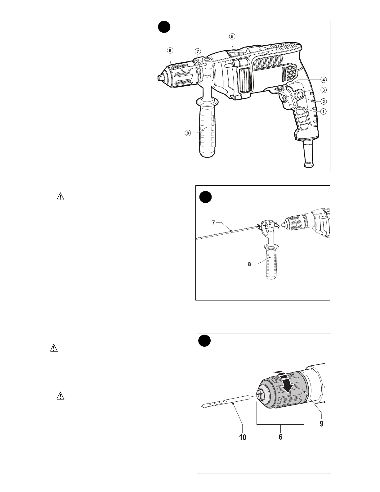
ATTACHING THE SIDE HANDLE (FIGURE B)
The drill is equipped with a side handle, and
must be installed properly to control the drill.
• Turn the grip counterclockwise until you
can slide the side handle (8) onto the front
of the tool as shown.
• Rotatethe sidehandleintothe desiredposition.
• Insert the depth stop (7) into the mounting
hole as shown.
• Set the drilling depth as described under “Setting the Drilling Depth”.
• Tighten the side handle by turning the grip clockwise. Make sure that the side handle is
secure and does not slip.
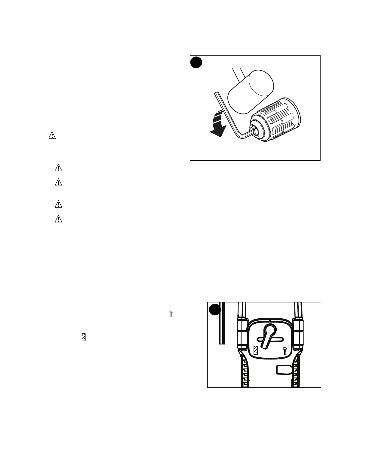
INSERTING A DRILL BIT OR OTHER
ACCESSORY (FIGURE C)
WARNING: Do not attempt to
tighten drill bits (or any other accessory)
by gripping the front part of the chuck
and turning the tool on. Damage to the
chuck and personal injury may occur when
changing accessories.
WARNING: Always ensure the bit
is secure before starting the tool. A
loose bit may eject from tool causing
possible personal injury.
• Open the chuck (6) by turning the collar
counterclockwise (when viewed from the
chuck end).
• Insertthe accessory shaft(10)intothe chuckto
about 3/4in. (19mm) depth,centeredinthe
jaws.
5
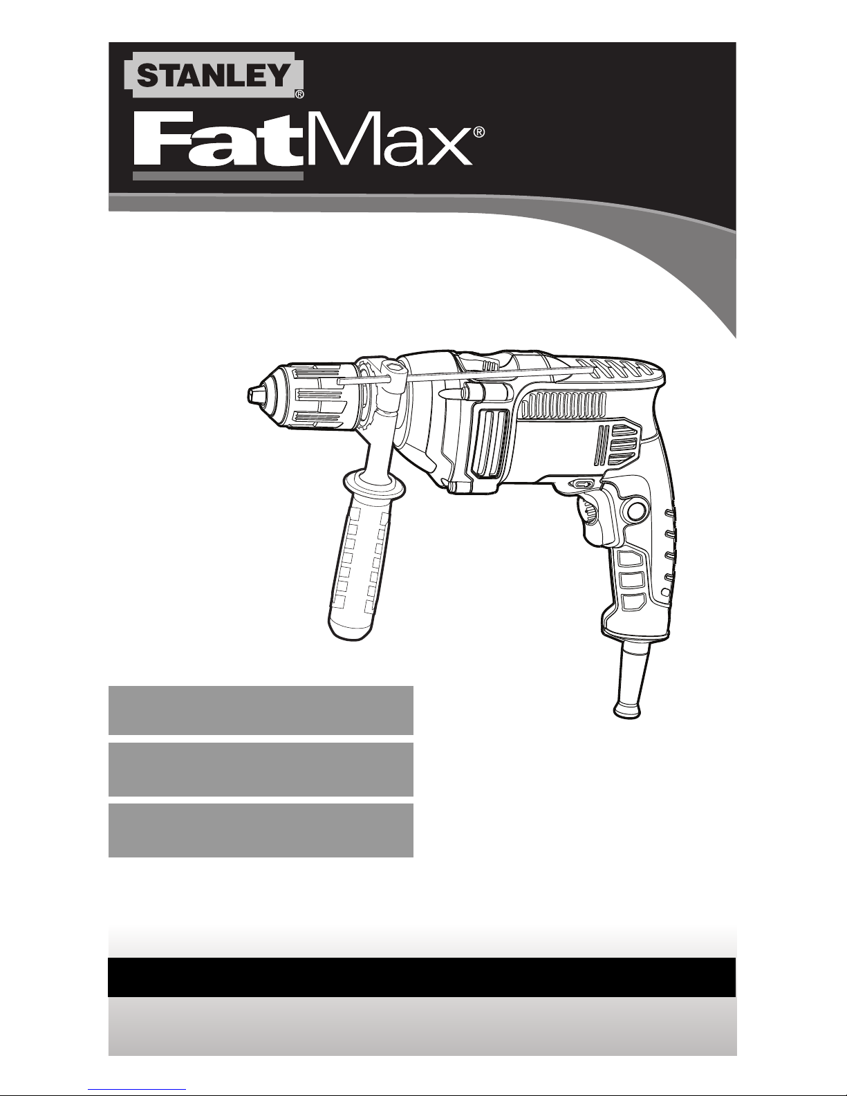
FUNCTIONAL
DESCRIPTION
Figure A
1. Variable speed switch
2. Lock-on button
3. Variable speed control knob
4. Forward/Reverse slider
5. Drilling mode selector
6. Keyed chuck
7. Depth stop rod
8. Side handle
A
B
C
Page 6
6
• Tighten chuck collar by turning the collar clockwise.
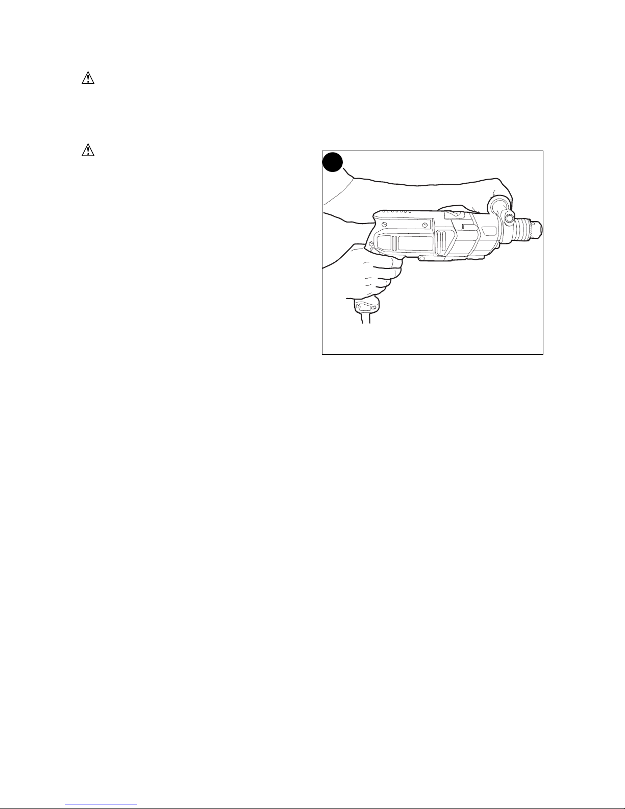
REMOVING AND ATTACHING THE CHUCK (FIGURE D)
• Open the chuck as far as possible.
• Remove the chuck retaining screw, located in the chuck, by turning it clockwise using a
screwdriver (lefthand thread).
• Tighten an Allen key of 1/4 inch or greater
size (not supplied) into the chuck and strike
it with a soft hammer in a counterclockwise
direction as shown.
• Remove the Allen key.
• Remove the chuck by turning it
counterclockwise.
• Toattachthe chuck, screwitontothe spindle
and secure itwiththechuck retainingscrew.
OPERATING INSTRUCTIONS
WARNING: To reduce the risk of
serious personal injury, read, understand
and follow all safety warnings and
instructions prior to using tool.
WARNING:Itisimportant tosupport the workproperlyand toholdthe drill firmly
withbothhands toprevent lossofcontrolwhich could cause personal injury.
WARNING: Do not attempt to tighten drill bits (or any other accessory) by
gripping the front part of the chuck and turning the tool on. Damage to the chuck
and personal injury may occur when changing accessories.
WARNING: To reduce the risk of injury, always unplug drill from power supply
before making any adjustments or changing accessories.
WARNING: Toreducetheriskofinjury,letthetoolworkat itsownpace.Donotoverload.
SWITCHING ON AND OFF
• To switch the tool on, press the variable speed switch (1).The toolspeed depends onhow far
you press the switch. If the tool has a variable speed control knob (3), set it to the required speed
range.As a general rule, use low speeds for large diameter drill bits andhigh speeds for smaller
diameter drill bits.
• For continuous operation, press the lock-on button (2)and release the variable speed switch. This
option is available only at full speed or at any speed preset with the variable speed control knob
(3).This option does not work inreverse rotation.
• To switch the tool off, release the variable speed switch. To switch the tool off when in continuous
operation,press the variable speed switch once more and release it.
SELECTING THE DRILLING MODE (FIGURE E)
• For drilling in masonry, set the drilling mode
selector (5) to the “hammer symbol” position.
• For drilling in other materials and for fastening,
set the drilling mode selector (5) to the “drill
symbol” position.
SELECTING THE DIRECTION OF ROTATION
For drilling and for tightening screws, use forward
(clockwise) rotation. For loosening screws or
removing a jammed drill bit, use reverse
(counterclockwise) rotation.
Note: The direction of rotation is also depicted by
an arrow on theforward/reverse slider (4).
Never change the direction of rotation while the motor is running.
• To select forward rotation, push the forward/reverse slider (4) to the left (when viewed
from the chuck end).
• To select reverse rotation, push the forward/reverse slider (4) to the right (when viewed
from the chuck end).
SETTING THE DRILLING DEPTH
• Slacken the side handle (8) by turning the grip counterclockwise.
• Set the depth stop rod (7) to the desired position. The maximum drilling depth is equal
E
D
Page 7
7
to the distance between the tip of the drill bit and the front end of the depth stop rod.
• Tighten the side handle by turning the grip clockwise. Make sure that the side handle is
secure and does not slip.
WARNING: The drill should only be locked ON when it is held stationary in a drill
press stand or other means; NOT BY HAND! Never unplug the tool with the locking
feature engaged. To do so will cause the tool to start immediately the next time it is
plugged in.
DRILLING
WARNING: Hold drill firmly with one
hand on the grip and the other hand on the
side handle as shown in figure F.
• Always unplug the drill when attaching or
removing accessories. When attaching
accessories in the drill chuck, it is
important to securely tighten the chuck
using all three holes to prevent slippage.
When using a keyless chuck, hand tighten
firmly.
• Use sharp drill bits only.
• Support and secure work properly, as
instructed in the Safety Instructions.
• Useappropriate andrequired safety
equipment,asinstructedinthesafety
instructions.
• Secure and maintain work area, as
instructed in the safety instructions.
• Run the drill very slowly, using light pressure, until the hole is started enough to keep
the drill bit from slipping out of it.
• Apply pressure in a straight line with the bit. Use enough pressure to keep the bit biting
but not so much as to stall the motor or deflect the bit.
• Hold the drill firmly with both hands to control its twisting action.
• Drills equipped with a side handle must use the side handle.
• DO NOT CLICK THE TRIGGER OF A STALLED DRILL OFF AND ON IN AN ATTEMPT
TO START IT. DAMAGE TO THE DRILL CAN RESULT.
• Minimize stalling on breakthrough by reducing pressure and slowly drilling through the
last part of the hole.
• Keep the motor running while pullingthebit out ofa drilled hole.Thiswillhelpreducejamming.
DRILLING IN WOOD
Holes in wood can be made with the same twist drill bits used for metal or with spade
bits. These bits should be sharp and should be pulled out frequently when drilling to
clear chips from the flutes.
DRILLING IN METAL
Use a cuttinglubricant whendrilling metals.The exceptions are castironand brass whichshould be
drilled dry.The cuttinglubricantsthatworkbestare sulfurizedcutting oilorlardoil.
DRILLING IN MASONRY (Shift drill into hammer mode)
Use carbidetipped masonry bits. RefertoDrilling section.Keepevenforce onthe drill but not so
muchthatyou crackthe brittlematerial.Asmooth, evenflowofdustindicates the properdrilling rate.
F
Page 8

8
TROUBLESHOOTING
Problem Possible Cause Possible Solution
• Unit will not start. • Cord not plugged in. • Plug tool into a working outlet.
• Circuit fuse is blown. • Replace circuit fuse. (If the
product repeatedly causes the
circuit fuse to blow, discontinue
use immediately and have it
serviced at a Stanley FatMax
service center or authorized
servicer.)
• Circuit breaker is tripped. • Reset circuit breaker. (If the
product repeatedly causes the
circuit breaker to trip,
discontinue use immediately
and have it serviced at a
StanleyFatMax service center
or authorized servicer.)
• Cord or switch is damaged. • Have cord or switch replaced
at a Stanley FatMax Service
Center or Authorized Servicer
For assistance with your product, visit our website at www.stanleytools.com. for a list of
service centers, or call the Stanley FatMax Customer Care Center at (800) 262-2161
MAINTENANCE
Use only mild soap and damp cloth to clean the tool. Never let any liquid get inside the
tool; never immerse any part of the tool into a liquid.
REPLACEMENT PARTS
Use only identical replacement parts.For a parts list orto order parts, visit our service website at
www.stanleytools.com. Youcan alsoorder parts fromyour nearest Stanley FatMax Factory
Service Center or Stanley FatMax Authorized WarrantyServiceCenter. Or, you can call our
Customer Care Centerat (800) 262 2161.
SERVICE AND REPAIRS
Page 9

9
All quality tools will eventually require servicing and/or replacement of parts. For
information about Stanley FatMax, its factory service centers or authorized warranty
service centers, visit our website at www.stanleytools.com or call our Customer Care
Center at (800) 262 2161. All repairs made by our service centers are fully guaranteed
against defective material and workmanship. We cannot guarantee repairs made or
attempted by others.
You can also write to us for information at Stanley Tools, 701 E. Joppa Road, Towson,
Maryland 21286 - Attention: Product Service. Be sure to include all of the information
shown on the nameplate of your tool (model number, type, serial number, etc.).
ACCESSORIES
WARNING: Since accessories, other than those offered by Stanley FatMax have
not been tested with this product, use of such accessories with this tool could be
hazardous. To reduce the risk of injury, only Stanley FatMax recommended accessories
should be used with this product.
A complete line of accessories is available from your Stanley FatMax Factory Service
Center or a Stanley FatMax Authorized Warranty Service Center. Please visit our Web
Site www.stanleytools.com for a catalog or for the name of your nearest supplier.
THREE YEAR LIMITED WARRANTY
Stanley FatMax will repair or replace, without charge, any defects due to faulty materials
or workmanship for three years from the date of purchase for tools (two years for batteries).
This warranty does not cover part failure due to normal wear or tool abuse. For further
detail of warranty coverage and warranty repair information, visit
www.stanleytools.com or call (800) 262-2161. This warranty does not apply to
accessories or damage caused where repairs have been made or attempted by others.
This warranty gives you specific legal rights and you may have other rights which vary in
certain states or provinces.
In addition to the warranty, Stanley FatMax tools are covered by our:
1 YEAR FREE SERVICE: Stanley FatMax will maintain the tool and replace worn parts
caused by normal use, for free, any time during the first year after purchase.
90 DAY MONEY BACK GUARANTEE: If you are not completely satisfied with the
performance of your Stanley FatMax Power Tool for any reason, you can return it within
90 days from the date of purchase with a receipt for a full refund – no questions asked.
LATIN AMERICA: This warranty does not apply to products sold in Latin America. For
products sold in Latin America, see country specific warranty information contained in
the packaging, call the local company or see website for warranty information.
To register your tool for warranty service visit our website at www.stanleytools.com
WARNING LABEL REPLACEMENT
If your warning labels become illegible or are missing, call (800) 262-2161 for a free
replacement.
Imported by
Stanley Tools
701 E. Joppa Road
Towson, Maryland 21286
Page 10
10
N° de catalogue
FME140
MANUEL D'INSTRUCTIONS
Marteau perforateur 7,0 A, 13 mm (1/2 po)
CONSERVER CE MANUEL POUR UN USAGE ULTÉRIEUR.
Page 11

11
Avertissements de sécuritégénérauxpourlesoutils électriques
AVERTISSEMENT : Lire tous les avertissements de sécurité et toutes
les directives. Le non-respect des avertissements et des directives pourrait se
solder par un choc électrique, un incendie et/ou une blessure grave.
Conserver tous les avertissements et toutes les directives pour un usage ultérieur.
Le terme «outil électrique» cité dans les avertissements se rapporte à votre
outil électrique à alimentation sur secteur (avec fil) ou par piles (sans fil).
1) Sécurité du lieu de travail
a) Tenir la zone de travail propre et bien éclairée. Les endroits sombres sont
souvent des causes d'accidents.
b) Ne pas faire fonctionner dʼoutils électriques dans un milieu déflagrant, soit en
présence deliquidesinflammables, degaz ou depoussière. Les outils
électriques produisent des étincelles qui peuvent enflammer la poussière ou les vapeurs.
c) Éloigner les enfants et les curieux au moment dʼutiliser un outil électrique.
Une distraction pourrait vous en faire perdre la maîtrise.
2) Sécurité en matière dʼélectricité
a) Les fiches des outils électriques doivent correspondre à la prise. Ne jamais
modifier la fiche en aucune façon. Ne jamais utiliser de fiche dʼadaptation avec
un outil électrique mis à la terre. Le risque de choc électrique sera réduit par
lʼutilisation de fiches non modifiées correspondant à la prise.
b) Éviter tout contact physique avec des surfaces mises à la terre comme des
tuyaux, des radiateurs, des cuisinières et des réfrigérateurs. Le risque de
choc électrique est plus élevé si votre corps est mis à la terre.
c) Ne pas exposer les outils électriques à la pluie ou à d'autres conditions où il
pourrait être mouillé. La pénétration de lʼeau dans un outil électrique augmente
le risque de choc électrique.
d) Ne pas utiliser abusivement lecordon dʼalimentation. Nejamais utiliser le
cordon pourtransporter, tirer ou débrancherun outil électrique. Tenirle
cordon éloigné de lachaleur, de lʼhuile, desbords tranchantsou des pièces mobiles.
Les cordons endommagés ou emmêlés augmentent les risques de choc électrique.
e) Pour lʼutilisation dʼun outil électrique à lʼextérieur, se servir dʼune rallonge
convenant à une telle utilisation. Lʼutilisation dʼune rallonge conçue pour
lʼextérieur réduit les risques de choc électrique.
f) Sʼil est impossible dʼéviter lʼutilisation dʼun outil électrique dans un endroit
humide, brancher lʼoutil dans une prise ou sur un circuit dʼalimentation
dotés dʼun disjoncteur de fuite à la terre (GFCI). Lʼutilisation de ce type de
disjoncteur réduit les risques de choc électrique.
3) Sécurité personnelle
a) Être vigilant, surveiller le travail effectué et faire preuve de jugement
lorsquʼun outil électrique est utilisé. Ne pas utiliser dʼoutil électrique en cas
de fatigue ou sous lʼinfluence de drogues, dʼalcool ou de médicaments. Un
LIGNES DIRECTRICES EN MATIÈRE DE SÉCURITÉ - DÉFINITIONS
Ilest important quevous lisiez et compreniez ce mode dʼemploi. Les informations quʼil contient
concernentVOTRE SÉCURITÉ etvisent à ÉVITER TOUT PROBLÈME. Les symboles cidessous servent à vous aider à reconnaître cette information.
DANGER : Indique une situation dangereuse imminente qui, si elle nʼest pas évitée,
causera la mort ou des graves blessures.
AVERTISSEMENT : Indique une situation potentiellement
dangereusequi, si elle nʼest pas évitée, pourrait causer la mort ou de graves blessures.
MISE EN GARDE : Indique une situation potentiellement dangereusequi, si elle nʼest
pas évitée,pourraitcauser des blessures mineures oumodérées.
AVIS : Utilisé sans le symbole dʼalerte à la sécurité, indique une situationpotentiellement
dangereusequi, si elle nʼest pas évitée, peutrésulter en des dommages à la propriété.
Page 12

12
simple moment dʼinattention en utilisant un outil électrique peut entraîner des
blessures corporelles graves.
b) Utiliserdes équipements deprotection individuelle. Toujours porter une
protection oculaire. Lʼutilisation dʼéquipements de protection comme un masque
antipoussière, des chaussures antidérapantes, un casque de sécurité ou des protecteurs
auditifs lorsque la situation le requiert réduira les risques de blessures corporelles.
c) Empêcher les démarrages intempestifs. Sʼassurer que lʼinterrupteur se
trouve à la position dʼarrêt avant de relier lʼoutil à une source dʼalimentation
et/ou dʼinsérer un bloc-piles, de ramasser ou de transporter lʼoutil.
Transporter un outil électrique alors que le doigt repose sur lʼinterrupteur ou
brancher un outil électrique dont lʼinterrupteur est à la position de marche risque
de provoquer un accident.
d) Retirer toute clé de réglage ouclé standard avant de démarrer lʼoutil. Une clé standard
ou une clé de réglage attachée à une partie pivotante peut causer des blessures.
e) Ne pas trop tendre les bras. Conserver son équilibre en tout temps. Cela
permet de mieux maîtriser lʼoutil électrique dans les situations imprévues.
f) Sʼhabiller de manière appropriée. Ne pas porter de vêtements amples ni de
bijoux. Garder les cheveux, les vêtements et les gants à lʼécart des pièces
mobiles. Les vêtements amples, les bijoux ou les cheveux longs risquent de
rester coincés dans les pièces mobiles.
g) Si des composants sont fournis pour le raccordement de dispositifs de
dépoussiérage et de ramassage, sʼassurer que ceux-ci sont bien raccordés
et utilisés. Lʼutilisation dʼun dispositif de dépoussiérage peut réduire les dangers
engendrés par les poussières.
4) Utilisation et entretien dʼun outil électrique
a) Ne pas forcer un outil électrique. Utiliser lʼoutil électrique approprié à
lʼapplication. Lʼoutil électrique approprié effectuera un meilleur travail, de façon
plus sûre et à la vitesse pour laquelle il a été conçu.
b) Ne pas utiliser un outil électrique dont lʼinterrupteur est défectueux. Tout outil électrique
dont lʼinterrupteur est défectueux est dangereux et doit être réparé.
c) Débrancher la fiche du secteur ou le bloc-piles de lʼoutil électrique avant de
faire tout réglage ou changement dʼaccessoire, ou avant de ranger lʼoutil
électrique. Ces mesures préventives réduisent les risques de démarrage
accidentel de lʼoutil électrique.
d) Ranger les outils électriques hors de la portée des enfants, et ne permettre
à aucune personne nʼétant pas familière avec un outil électrique (ou son
manuel dʼinstruction) dʼutiliser ce dernier. Les outils électriques deviennent
dangereux entre les mains dʼutilisateurs inexpérimentés.
e) Entretenir les outils électriques. Vérifier les pièces mobiles pour sʼassurer
quʼelles sont bien alignées et tournent librement, quʼelles sont en bon état
et ne sont affectées par aucun trouble susceptible de nuire au bon
fonctionnement de lʼoutil électrique. En cas de dommage, faire réparer
lʼoutil électrique avant toute nouvelle utilisation. Beaucoup dʼaccidents sont
causés par des outils électriques mal entretenus.
f) Sʼassurer que les outils de coupe sont aiguisés et propres. Les outils de
coupe bien entretenus et affûtés sont moins susceptibles de se coincer et sont
plus faciles à contrôler.
g) Utiliser lʼoutil électrique, les accessoires, les forets, etc. conformément aux
présentes directives en tenant compte des conditions de travail et du travail
à effectuer. Lʼutilisation dʼun outil électrique pour toute opération autre que celle
pour laquelle il a été conçu est dangereuse.
5) Réparation
a) Faire réparer lʼoutil électrique par un réparateur professionnel en nʼutilisant
que des pièces de rechange identiques. Cela permettra de maintenir une
utilisation sécuritaire de lʼoutil électrique.
CONSIGNES DE SÉCURITÉ PARTICULIÈRES
• Porter des protecteurs auditifs si une perceuse à percussion est utilisée. Une
exposition au bruit peut entraîner une perte auditive.
• Utiliser les poignées auxiliaires fournies avec l’outil. Une perte de maîtrise de lʼoutil
peut entraîner des blessures corporelles.
Page 13

13
• Saisir l’outil électrique par ses surfaces de prises isolées lorsque l’outil peut
entrer en contact avec des fils cachés ou son cordon. En cas de contact avec un fil
sous tension, les pièces métalliques de lʼoutil seront sous tension et lʼutilisateur subira des
secousses électriques.
• Utiliser des bridesdefixationouunautre dispositifdefixationpermettant defixer
solidementetdesoutenirlapiècesur une plateformestable. Tenirlapièce aveclamainou
contresoncorps larendinstableetrisquedeprovoqueruneperte demaîtrisedelʼoutil.
• Tenir les cheveux, les vêtements et les gants loin des évents. En effet, les évents
cachent souvent des pièces mobiles qui risquent de happer ces articles.
• Maintenir les poignées sèches, propres, exemptes d’huile et de graisse. On
recommande d’utiliser des gants de caoutchouc. Cela permet de mieux
maîtriser lʼoutil.
AVERTISSEMENT : TOUJOURS porter des lunettes de sécurité. Les
lunettes de vue ne constituent PAS des lunettes de sécurité. Utiliser
également un masque facial ou anti-poussière si l’opération de découpe
génère de la poussière. TOUJOURS PORTER UN ÉQUIPEMENT DE
PROTECTION HOMOLOGUÉ :
• protection oculaire conforme à la norme ANSI Z87.1 (CAN/CSA Z94.3);
• protection auditive ANSI S12.6 (S3.19);
• protection des voies respiratoires conformes aux normes NIOSH/OSHA/MSHA.
AVERTISSEMENT :certains outils électriques, tels que les sableuses, les
scies, les meules, les perceuses ou certains autres outils de construction,
peuvent produire de la poussière contenant des produits chimiques reconnus
par l’État de la Californie comme étant susceptibles d’entraîner le cancer, des
malformations congénitales ou pouvant être nocifs pour le système
reproductif. Parmi ces produits chimiques, on retrouve :
· le plomb dans les peintures à base de plomb,
· la silice cristalline dans les briques et le ciment et autres produits de maçonnerie,
· lʼarsenic et le chrome dans le bois de sciage ayant subi un traitement chimique.
Le risque associé à de telles expositions varie selon la fréquence avec laquelle on
effectue ces travaux. Pour réduire lʼexposition à de tels produits, il faut travailler dans un
endroit bien aéré et utiliser le matériel de sécurité approprié, tel un masque
anti-poussières spécialement conçu pour filtrer les particules microscopiques.
• Éviter tout contact prolongé avec la poussière soulevée par cet outil ou autres
outils électriques. Porter des vêtements de protection et nettoyer les parties
exposées du corps à l’eau savonneuse. Sʼassurer de bien se protéger afin dʼéviter
dʼabsorber par la bouche, les yeux ou la peau des produits chimiques nocifs.
AVERTISSEMENT : Cetoutil peutproduireetrépandre delapoussière
susceptible decauserdes dommagessérieuxetpermanents ausystème respiratoire.
Toujoursutiliser unappareilrespiratoireanti-poussières approprié approuvépar leNIOSH ou
lʼOSHA. Diriger les particulesdanslesensopposéduvisageetducorps.
SYMBOLES
• Lʼétiquette apposée sur votre outil pourrait comprendre les symboles suivants. Les
symboles et leurs définitions sont indiqués ci-après :
V ..............volts A................ampères
Hz ............hertz W ..............watts
min............minutes ............courant alternatif
..........courant continue non............régime à vide
..............Construction de classe I
(mis à la terre)
..............Construction classe II
............
borne de terre
............symbole dʼalerte à la opm ............oscillations par minute
sécurité
Page 14

14
• En cas dʼutilisation dʼune rallonge, sʼassurer que les valeurs nominales de la rallonge
utilisée correspondent bien à celles de lʼoutil alimenté. Lʼusage dʼune rallonge de calibre
insuffisant causera une chute de tension entraînant perte de puissance et surchauffe. Le
tableau ci-dessous illustre les calibres à utiliser selon la longueur de rallonge et lʼintensité
nominale indiquée sur la plaque signalétique. En cas de doutes, utiliser le calibre suivant.
Plus le calibre est petit, plus la rallonge peut supporter de courant.
Calibre minimal des cordons de rallonge
Tension Longueur totale du cordon en pieds
120V 0-25 26-50 51-100 101-150
(0-7,6m) (7,6-15,2m) (15,2-30,4m) (30,4-45,7m)
240V 0-50 51-100 101-200 201-300
(0-15,2m) (15,2-30,4m) (30,4-60,9m) (60,9-91,4m)
Intensité (A)
Au Au Calibre moyen des fils (AWG)
moins plus
0-6 18 16 16 14
6-10 18 16 14 12
10 - 12 16 16 14 12
12 - 16 14 12 Non recommandé
DESCRIPTION
FONCTIONNELLE - FIGURE A
1. Détente de vitesse variable
2. Bouton de verrouillage
3. Molette de commande à
vitesse variable
4. Commutateur coulissant
avant/arrière
5. Sélecteur de mode de
perçage
6. Mandrin à clé
7. Tige de limitation de la
profondeur
8. Poignée latérale
A
Page 15

15
AVERTISSEMENTS DE SÉCURITÉ ET DIRECTIVES : PERCEUSES
AVERTISSEMENT :Saisir fermement la perceuse avec les deux mains afin de
maîtriser le mouvement de torsion et dʼéviter dʼen perdre la maîtrise ce qui pourrait
entraîner des blessures corporelles. En cas de blocage, relâcher la détente
immédiatement et déterminer la raison du blocage avant de redémarrer.
ASSEMBLAGE
AVERTISSEMENT :
Pour réduire le risque de blessures avant lʼassemblage,
sʼassurer que lʼoutil est éteint et débranché.
FIXATION DE LA POIGNÉE LATÉRALE - (FIG. B)
Si la perceuse est dotée dʼune poignée latérale, veuillez lʼinstaller correctement
pour bien maîtriser la perceuse.
• Tourner la poignée en sens antihoraire jusquʼà ce que la poignée latérale (8) se glisse
en place à lʼavant de lʼoutil comme indiqué.
• Pivoter la poignée latérale à la position désirée.
• Insérer la butée de profondeur (7) dans le trou réservé à cette fin comme indiqué.
E
D
F
C
B
Page 16

16
•
Régler la butée de profondeur comme décrit sous la rubrique « Réglage de la
profondeur de perçage ».
• Serrer la poignée latérale en la tournant en sens horaire. Sʼassurer que la poignée
latérale est bien fixée et ne glisse pas.
INSÉRER UNE MÈCHE OU UN AUTRE ACCESSOIRE (FIG. C)
AVERTISSEMENT : ne pas essayer de resserrer les mèches (ou tout autre
accessoire) en saisissant la partie avant du mandrin et en mettant l’outil en
marche. Lors du changement dʼaccessoire, il y a risque dʼendommager le mandrin et
dʼentraîner des blessures corporelles.
AVERTISSEMENT : toujourss’assurerque lamèche estbienfixéeavantde
démarrerl’outil. Unemèchedesserréepeutêtreéjectéedelʼoutil etcauserdes blessurescorporelles.
• Tourner la bague en sens antihoraire (si on se place à lʼextrémité du mandrin) pour
ouvrir les mâchoires du mandrin (6).
• Insérer lʼemmanchement de lʼaccessoire (10) au centre des mâchoires du mandrin à
une profondeur dʼenviron 19 mm (3/4 po).
• Puisserrerlemandrin à lamainentournantlecollierensens horaire.
RETRAIT ET FIXATION DU MANDRIN (FIG. D)
• Ouvrir autant que possible les mâchoires du mandrin.
• Dévisser en sens horaire avec un tournevis (filetage gauche) et retirer la vis de sûreté
du mandrin logée sur ce dernier.
• Insérer etserrerune cléAllende6,35mm(1/4 po) ouplus(clénon comprise)dansles mâchoires
dumandrinetlafrapper ensens antihoraire avecunmarteau-caoutchouc
• puis retirer la clé Allen.
• Retirer le mandrin en le tournant en sens antihoraire.
• Pourfixer unmandrin,levissersur labrocheetlefixer aveclavis desûretédumandrin.
FONCTIONNEMENT
AVERTISSEMENT :
pour réduire le risque de blessure personnelle grave,
veuillez lire, assimiler et suivre tous les avertissements de sécurité et toutes les
directives avant dʼutiliser lʼoutil.
AVERTISSEMENT : Pour éviter toute blessure corporelle, soutenir
correctement la pièce et tenir fermement la perceuse avec les deux mains pour
empêcher une perte de maîtrise de l’outil.
AVERTISSEMENT : ne pas essayer de resserrer les mèches (ou tout autre
accessoire) en saisissant la partie avant du mandrin et en mettant l’outil en
marche. Lors du changement dʼaccessoires, il y a risque dʼendommager le mandrin et
dʼentraîner des blessures corporelles.
AVERTISSEMENT : pour réduire lerisque deblessures,toujours débrancher la
perceuseavecdʼeffectuer quelque ajustement que cesoitoudechanger dʼaccessoires.
AVERTISSEMENT : pour réduire les risques de blessures, laisser lʼoutil
travailler à sa propre vitesse. Ne pas le surcharger.
MISE EN MARCHE ET ARRÊT
•Pourmettrelʼoutil enmarche, appuyer sur ladétente àvitessevariable (1).Lavitessedelʼoutilvarie
selon lapressionquʼon exerce sur ladétente.Silʼoutil est pourvudʼune molette decommandeà
vitesse variable(3),laréglerà lagamme devitessesexigée.Règlegénérale, onutiliseles vitesses
bassespour les mèchesdegrand diamètreetles vitessesélevées pourcellesdepetit diamètre.
•Pourunfonctionnementcontinu,appuyersurleboutondeverrouillage(2)etrelâcherladétenteàvitesse
variable.Cetteoptionestofferteuniquementàpleinrégimeouàtoutevitesseprérégléeaveclamolettede
commandeàvitessevariable(3).Cetteoptionnefonctionnepasenrotationarrière.
•Pouréteindrelʼoutil,relâcherladétente à vitesse variable. Pourmettrelʼoutilhorstension enmode
defonctionnementcontinu, appuyersur ladétente à vitesse variableune fois,puislarelâcher.
Page 17

17
SÉLECTION DU MODE PERCEUSE (FIG. E)
• Pour perforer de la maçonnerie, régler le sélecteur de mode de travail (5) sur le «
symbole du marteau » .
• Pour le perçage d'autres matériaux et pour le vissage, régler le sélecteur de mode de
perçage (5) sur le « symbole de la perceuse » .
SÉLECTION DU SENS DE ROTATION
Pour percer et serrer des vis, utiliser la rotation avant (sens horaire). Pour desserrer des
vis ou retirer une mèche de perceuse coincée, utiliser la rotation arrière (sens
antihoraire).
Remarque : dispositif de glissement avant/arrière comporte également une illustration
du sens de rotation (4).
Ne jamais permuter entre les directions de rotation avec le moteur de la perceuse en
fonctionnement.
• Pour sélectionner la rotation avant, coulisser le dispositif de glissement avant/arrière (4)
vers la gauche (si on se place à lʼextrémité du mandrin).
• Pour sélectionner la rotation avant, coulisser le dispositif de glissement avant/arrière (4)
vers la droite (si on se place à lʼextrémité du mandrin).
RÉGLAGE DE LA PROFONDEUR DE PERÇAGE
• Donner du mou à la poignée latérale (8) en la tournant en sens antihoraire.
• Régler la butée de profondeur (7) à la position désirée. La profondeur maximale de
perçage est équivalente à la distance entre la pointe de la mèche et lʼextrémité avant de
la butée de profondeur.
• Serrer la poignée latérale en la tournant en sens horaire. Sʼassurer que la poignée
latérale est bien fixée et ne glisse pas.
AVERTISSEMENT : Verrouiller la perceuse en position de MARCHE
uniquement si elle est fixe sur un socle de perceuse à colonne ou un autre dispositif de
fixation. NE JAMAIS LA VERROUILLER LORS DʼUNE UTILISATION MANUELLE ! Ne
jamais débrancher lʼoutil avec le dispositif de verrouillage engagé. Le non-respect de
cette mesure provoquera le démarrage immédiat de lʼoutil dès le prochain branchement.
MODE PERÇAGE
AVERTISSEMENT : Tenir fermement la perceuse en saisissant la poignée dʼune
main et en plaçant lʼautre main sur la poignée latérale comme montré à la figure F.
• Toujours débrancher la perceuse lors de lʼinsertion ou du retrait dʼaccessoires. Lors de
lʼinsertion dʼaccessoires dans le mandrin de la perceuse, il est primordial de serrer
solidement le mandrin en utilisant les trois trous pour prévenir tout glissement. Dans le
cas dʼun mandrin sans clé, serrer fermement à la main.
• Utiliser des mèches aiguisées seulement.
• Bien soutenir et fixer la pièce, conformément aux consignes de sécurité.
• Utiliser le matériel de sécurité approprié, conformément aux consignes de sécurité.
• Garder lazonedetravail propreetsécuritaire,conformémentaux consignesdesécurité.
• Faire fonctionner la perceuse très lentement en exerçant une légère pression, jusquʼà
ce que le trou soit suffisamment profond pour empêcher la mèche dʼen sortir.
• Appliquer une pression en ligne droite au moyen de la mèche en exerçant juste assez
de pression pour permettre à la mèche de mordre dans la pièce, en évitant de caler le
moteur ou de faire dévier la mèche.
• Tenir fermement l’outil avec les deux mains afin de contrôler sa rotation.
• Utiliser en tout temps la poignée latérale des perceuses qui en sont dotées.
• NE PAS ENFONCER ET RELÂCHER LA GÂCHETTE À PLUSIEURS REPRISES
POUR ESSAYER DE REDÉMARRER LA PERCEUSE AFIN DʼÉVITER DE
LʼENDOMMAGER.
• Réduire les risques de calage au minimum en réduisant la pression lorsque la mèche
perce le matériau et en perçant lentement la dernière section du trou.
• Maintenir le moteur en marche lorsquʼon retire la mèche du trou percé afin dʼéviter
quʼelle reste coincée.
Page 18

18
PERÇAGE DU BOIS
On peut percer le bois au moyen des mèches hélicoïdales quʼon utilise pour le métal ou
de mèches à vrille. On doit utiliser des mèches bien aiguisées et les sortir fréquemment
pour enlever les copeaux restés coincés dans les cannelures.
PERÇAGE DU MÉTAL
Utiliser une huile de coupe lorsquʼon perce des métaux, à lʼexception de la fonte et du
laiton, car ces derniers doivent être percés à sec. Pour cette tâche, les meilleurs
lubrifiants sont lʼhuile sulfurée et lʼhuile de lard.
PERÇAGE DE LA MAÇONNERIE
Utiliser des mèches à pointe carburée (voir la section « Mode perçage »). Maintenir une
pression uniforme sur la perceuse, sans trop forcer pour éviter de fissurer les matériaux
plus cassants. La vitesse choisie est appropriée lorsque la poussière est soulevée
uniformément et régulièrement.
ENTRETIEN
Nʼutiliser quʼun détergent doux et un chiffon humide pour nettoyer lʼappareil. Ne jamais
laisser de liquide pénétrer dans lʼappareil et nʼimmerger aucune partie de lʼappareil dans
un liquide.
PIÈCES DE RECHANGE
Utiliser seulement des pièces de rechange identiques. Pour obtenir une liste des
pièces ou pour en commander, consulter notre site Web de réparation à lʼadresse
suivante : www.stanleytools.com. Il est également possible de commander des
pièces auprès du centre de réparation en usine Stanley FatMax ou du centre de
réparation sous garantie agréé Stanley FatMax le plus proche. Sinon, appeler notre
service à la clientèle au 800 262-2161.
DÉPANNAGE
Problème Cause possible Solutionpossible
• Lʼappareil refuse de • Cordon dʼalimentation • Brancher lʼoutil dans
démarrer. non branché. une prise qui fonctionne.
• Le fusible du circuit est grillé. • Remplacer le fusible du
circuit. (Si le produit fait
griller de façon répétée
le fusible du circuit, arrêter
immédiatement dʼutiliser le
produit et le faire réparer
dans un centre de réparation
Stanley FatMa
x ou un centre
de réparation autorisé.)
• Le disjoncteur est déclenché. • Remettre le disjoncteur à
zéro . (Si le produit fait
déclencher de façon
répétée le disjoncteur,
arrêter immédiatement
dʼutiliser le produit et le
faire réparer dans un
centre de réparation
Stanley
FatMa
x ou un centre de
réparation autorisé.)
• Le cordon dʼalimentation • Faire remplacer le
ou la prise de courant est cordon ou lʼinterrupteur
endommagé(e). au centre de réparation
Stanley FatMa
x ou à un
centre de réparation
autorisé.
Pour obtenir de lʼaide relativement au produit, consulter notre site Web à lʼadresse
suivante : www.stanleytools.com pour obtenir une liste des centres de réparation ou
appeler le centre de service à la clientèle de Stanley FatMax au 800 262-2161.
Page 19

19
ENTRETIEN ET RÉPARATION
Tous les outils de qualité finissent par demander un entretien ou un changement de
pièce. Pour de plus amples renseignements à propos de Stanley FatMax, ses centres
de réparation en usine ou ses centres de réparation sous garantie agréés, visiter son site
Web à lʼadresse suivante : www.stanleytools.com ou communiquer avec son centre de
service à la clientèle en composant le 800 262-2161. Toutes les réparations effectuées
dans nos centres de réparation sont entièrement garanties contre les défauts de
matériaux et de main-dʼœuvre. Nous ne pouvons garantir les réparations effectuées en
partie ou totalement par dʼautres.
Vous pouvez aussi nous écrire pour obtenir de lʼinformation à lʼadresse suivante : Stanley
Tools, 701 E. Joppa Road, Towson, Maryland 21286 - Attention: Product Service.
Sʼassurer dʼindiquer toutes les informations figurant sur la plaque signalétique de lʼoutil
(numéro du modèle, type, numéro de série, etc.).
ACCESSOIRES
AVERTISSEMENT : Puisque les accessoires autres que ceux offerts par Stanley
FatMax nʼont pas été testés avec ce produit, lʼutilisation de ceux-ci avec lʼoutil pourrait
sʼavérer dangereuse. Pour réduire le risque de blessures, utiliser exclusivement les
accessoires Stanley FatMax recommandés avec le produit. Les centres de réparation de
lʼusine Stanley FatMax ou les centres de réparation sous garantie autorisés
Stanley FatMax sont en mesure de vous fournir la gamme complète dʼaccessoires.
Consulter le site Web www.stanleytools.com pour obtenir un catalogue ou le nom du
fournisseur local.
GARANTIE RESTREINTE DE TROIS ANS
Stanley FatMax réparera ou remplacera gratuitement les outils défectueux présentant des
défauts de matériau ou de fabrication pendant trois ans à compter de la date dʼachat des
outils (garantie de deux ans pour les blocs-piles). Cette garantie ne couvre pas des
défaillances de pièce dues à une usure normale ou à une mauvaise utilisation de lʼoutil.
Pour plus de détails relatifs à la couverture de la garantie et aux réparations sous
garantie, visitez le site Web www.stanleytools.com ou composez le 800 262-2161. Cette
garantie ne sʼapplique pas aux accessoires ni aux dommages causés par des réparations
réalisées ou tentées par des tiers. Cette garantie vous accorde des droits légaux
spécifiques et il est possible que vous ayez dʼautres droits qui varient dʼun État ou dʼune
province à lʼautre.
En plus de la garantie, les outils Stanley FatMax sont couverts par notre :
SERVICE DʼENTRETIEN GRATUIT DE 1 AN : Stanley FatMax entretiendra lʼoutil et
remplacera gratuitement les pièces usées par une utilisation normale en tout temps
pendant la première année à compter de la date dʼachat.
GARANTIE DE REMBOURSEMENT DE 90 JOURS : Si vous nʼêtes pas entièrement
satisfait des performances de votre outil électrique Stanley FatMax pour quelque raison
que ce soit, vous pouvez le retourner accompagné dʼun reçu dans les 90 jours suivant
la date dʼachat et nous vous rembourserons entièrement – sans poser de questions.
AMÉRIQUE LATINE : Cette garantie ne sʼapplique pas aux produits vendus en
Amérique latine. Pour les produits vendus en Amérique latine, veuillez consulter les
informations relatives à la garantie propre au pays, présentes dans lʼemballage,
appelez lʼentreprise locale ou consultez le site Web pour connaître les informations
relatives à la garantie.
Pour enregistrer votre outil en vue dʼobtenir un service de garantie, consultez notre site
Web à lʼadresse suivante : www.stanleytools.com.
REMPLACEMENT DES ÉTIQUETTES DʼAVERTISSEMENT
Si les étiquettes dʼavertissement deviennent illisibles ou sont manquantes, composez
le 800 262-2161 pour en obtenir le remplacement gratuit.
Imported by / Importé par
Stanley Tools
701 E. Joppa Road
Towson, Maryland 21286
Page 20

20
Catálogo N° FME105
MANUAL DE INSTRUCCIONES
Taladro percutor 13 mm (1/2 pulgada) y 7 amperios
CONSERVE ESTE MANUAL PARA FUTURAS CONSULTAS.
Page 21

21
PAUTAS DE SEGURIDAD/DEFINICIONES
Es importante que lea y comprenda este manual. La información que contiene se
relaciona con la protección de SU SEGURIDAD y la PREVENCIÓN DE PROBLEMAS.
Los símbolos que siguen se utilizan para ayudarlo a reconocer esta información.
PELIGRO: indica una situación de peligro inminente que, si no se evita, provocará la
muerte o lesiones graves.
ADVERTENCIA: indica una situación de peligro potencial que, si no se evita,
provocará la muerte o lesiones graves.
PRECAUCIÓN: indica una situación de peligro potencial que, si no se evita,
provocará lesiones leves o moderadas.
AVISO: utilizado sin el símbolo de alerta de seguridad indica una situación de peligro
potencial que, si no se evita, puede provocar daños en la propiedad.
Advertencias generales de seguridad para herramientaseléctricas
ADVERTENCIA: Lea todas las advertencias de seguridad e instrucciones El
incumplimiento de las advertencias e instrucciones puede provocar descargas
eléctricas, incendios o lesiones graves.
Conserve todas las advertencias e instrucciones para futuras consultas.
El término “herramienta eléctrica” incluido en las advertencias hace referencia
a las herramientas eléctricas operadas con corriente (con cable eléctrico) o a
las herramientas eléctricas operadas con baterías (inalámbricas).
1) Seguridad en el área de trabajo
a) Mantenga el área de trabajo limpia y bien iluminada. Las áreas abarrotadas y
oscuras propician accidentes.
b) No opere herramientas eléctricas en atmósferas explosivas, como ambientes
donde se encuentran líquidos, gases o polvo inflamables. Las herramientas
eléctricas originan chispas que pueden encender el polvo o los vapores.
c) Mantenga a los niños y espectadores alejados de la herramienta eléctrica en
funcionamiento. Las distracciones pueden provocar la pérdida de control.
2) Seguridad eléctrica
a) Los enchufes de la herramienta eléctrica deben adaptarse al tomacorriente. Nunca
modifique el enchufe de ninguna manera. No utilice ningún enchufe
adaptador con herramientas eléctricascon conexión a tierra. Los enchufes no
modificados y que se adaptan a los tomacorrientes reducirán el riesgo de descarga eléctrica.
b) Evite el contacto corporal con superficies puestas a tierra, como por
ejemplo tuberías, radiadores, rangos y refrigeradores. Existe mayor riesgo de
descarga eléctrica si su cuerpo está puesto a tierra.
c) No exponga las herramientas eléctricas a la lluvia o a condiciones de humedad.
Si ingresa agua a una herramienta eléctrica, aumentará el riesgo de descarga eléctrica.
d) No maltrate al cable. Nunca utilice el cable para transportar, tirar o
desenchufar la herramienta eléctrica. Mantenga el cable lejos del calor,
aceite, bordes afilados o piezas móviles. Los cables dañados o enredados
aumentan el riesgo de descarga eléctrica.
e) Al operar una herramienta eléctrica en el exterior, utilice un cable
prolongador adecuado para tal uso. Utilice un cable adecuado para uso en
exteriores a fin de reducir el riesgo de descarga eléctrica.
f) Si el uso de una herramienta eléctrica en un lugar húmedo es imposible de
evitar, utilice un suministro protegido con un interruptor de circuito por falla a
tierra (GFCI). El uso de un GFCI reduce el riesgo de descargas eléctricas.
3) Seguridad personal
a) Permanezca alerta, controle lo queestá haciendo y utilice elsentidocomún cuando
emplee una herramienta eléctrica. No utilice una herramienta eléctrica si está cansado o
Page 22

22
bajo el efecto de drogas, alcohol o medicamentos. Un momento de descuido mientras se
opera una herramienta eléctrica puede provocar lesiones personales graves.
b) Utilice equipos de protección personal. Siempre utilice protección para los
ojos. En las condiciones adecuadas, el uso de equipos de protección, como
máscaras para polvo, calzado de seguridad antideslizante, cascos o protección
auditiva, reducirá las lesiones personales.
c) Evite el encendido por accidente. Asegúrese de que el interruptor esté en la
posición de apagado antes de conectarlo a la fuente de energía o paquete de
baterías, o antes de levantar o transportar la herramienta. Transportar
herramientas eléctricas con el dedo apoyado en el interruptor o enchufar herramientas
eléctricas con el interruptor en la posición de encendido puede propiciar accidentes.
d) Retire las clavijas deajuste o llavesde tuercas antes de encender la
herramienta eléctrica. Una llave de tuercas o una clavija de ajuste que se deje conectada a
una pieza giratoria de la herramienta eléctrica pueden provocar lesiones personales.
e) No se estire. Conserve el equilibrio adecuado y manténgase parado
correctamente en todo momento. Esto permite un mejor control de la
herramienta eléctrica en situaciones inesperadas.
f) Use lavestimenta adecuada. No use ropas holgadas ni joyas.Mantengael cabello, la
ropa y los guantes alejados delas piezas en movimiento.Las ropas holgadas, las joyas o
el cabello largo pueden quedar atrapados en las piezas en movimiento.
g) Si se suministran dispositivos para la conexión de accesorios con fines de
recolección y extracción de polvo, asegúrese de que estén conectados y que
se utilicen correctamente. El uso de dispositivos de recolección de polvo puede
reducir los peligros relacionados con el polvo.
4) Uso y mantenimiento de la herramienta eléctrica
a) No fuerce la herramienta eléctrica. Utilice la herramienta eléctrica correcta
para el trabajo que realizará. La herramienta eléctrica correcta hará el trabajo
mejor y más seguro a la velocidad para la que fue diseñada.
b) No utilice la herramienta eléctrica si no puede encenderla o apagarla con el
interruptor. Toda herramienta eléctrica que no puede ser controlada mediante el
interruptor es peligrosa y debe ser reparada.
c) Desconecte el enchufe de la fuente de energía y/o el paquete de baterías de la
herramienta eléctrica antes de realizar ajustes, cambiar accesorios o
almacenar herramientas eléctricas. Estas medidas de seguridad preventivas
reducen el riesgo de encender la herramienta eléctrica en forma accidental.
d) Guarde las herramientas eléctricas que no están en uso fuera del alcance de
los niños y no permite que otras personas no familiarizadas con ella o con
estas instrucciones operen la herramienta. Las herramientas eléctricas son
peligrosas en las manos de usuarios no entrenados.
e) Mantenimiento de las herramientas eléctricas. Controle que no haya piezas
móviles mal alineadas o trabadas, piezas rotas y toda otra situación que
pueda afectar el funcionamiento de las herramientas eléctricas. Si encuentra
daños, haga reparar la herramienta eléctrica antes de utilizarla. Se producen
muchos accidentes a causa de las herramientas eléctricas que carecen de un
mantenimiento adecuado.
f) Mantenga las herramientas de corte afiladas y limpias. Las herramientas de
corte con mantenimiento adecuado, con los bordes de corte afilados son menos
propensas a trabarse y son más fáciles de controlar.
g) Utilice la herramienta eléctrica, los accesorios y las brocas de la herramienta,
etc. de acuerdo con estas instrucciones y teniendo en cuenta las condiciones
de trabajo y el trabajo que debe realizarse. El uso de la herramienta eléctrica para
operaciones diferentes de aquéllas para las que fue diseñada podría originar una
situación peligrosa.
5) Mantenimiento
a) Haga que una persona de reparaciones calificada realice el mantenimiento de
su herramienta eléctrica y utilice piezas de repuesto idénticas solamente.
Esto garantizará la seguridad de la herramienta eléctrica.
Page 23

23
NORMAS DE SEGURIDAD ESPECÍFICAS
• Utilice protectores auditivos con los taladros de impacto. La exposición al ruido
puede ocasionar la pérdida de la audición.
• Use los mangos auxiliares que se suministran con la herramienta. La pérdida del
control podría ocasionar lesiones personales.
• Sujete la herramienta eléctrica por las superficies aislantes cuando realice una
operación en que la herramienta pueda hacer contacto con cableados ocultos. Al
hacer contacto con un cable “vivo”, las partes metálicas de la herramienta se vuelven
“vivas” y pueden originar un choque al operador.
• Utilice abrazaderas u otra forma práctica para asegurar y sostener la pieza de
trabajo sobre una plataforma estable. Sostener el trabajo con la mano o contra el
cuerpo no brinda la estabilidad requerida y puede llevar a la pérdida del control.
• Mantenga el cabello, la ropa y los guantes alejados de los orificios de
ventilación. Los orificios de ventilación suelen cubrir piezas móviles donde estos
elementos se pueden enganchar.
• Mantenga los mangos secos, limpios y sin restos de aceite ni grasa. Se
recomienda utilizar guantes de goma. Éstos permitirán controlar la herramienta de
mejor manera.
ADVERTENCIA: USE SIEMPRE LENTES DE SEGURIDAD. Los anteojos de uso
diario NO son lentes de seguridad. Utilice también máscaras faciales o para polvo si el
corte produce polvillo. UTILICE SIEMPRE EQUIPOS DE SEGURIDAD
CERTIFICADOS:
• Protección para los ojos según la norma ANSI Z87.1 (CAN/CSA Z94.3)
• Protección auditiva según la norma ANSI S12.6 (S3.19)
• Protección respiratoria según las normas NIOSH/OSHA/MSHA
ADVERTENCIA: parte del polvo producido por las herramientas eléctricas al
lijar, aserrar, esmerilar, taladrar y realizar otras actividades de la construcción,
contiene productos químicos reconocidos por el Estado de California como
causantes de cáncer, defectos de nacimiento u otros problemas reproductivos.
Algunos de estos productos químicos son:
• el plomo de las pinturas de base plomo,
• la sílice cristalina de ladrillos, el cemento y otros productos de mampostería, y
• el arsénico y el cromo de la madera con tratamiento químico.
El riesgo derivado de estas exposiciones varía según la frecuencia con la que se realice
este tipo de trabajo. Para reducir la exposición a estos productos químicos: trabaje en
áreas bien ventiladas y trabaje con equipos de seguridad aprobados, como las
máscaras para polvo especialmente diseñadas para filtrar las partículas microscópicas.
• Evite el contacto prolongado con el polvo procedente del lijado, serrado,
esmerilado y taladrado eléctricos, así como de otras actividades del sector de la
construcción. Lleve ropa protectora y lave con agua y jabón las zonas
expuestas. Si permite que el polvo se introduzca en la boca u ojos o quede sobre la
piel, puede favorecer la absorción de productos químicos peligrosos.
ADVERTENCIA: El uso de esta herramienta puede generar o dispersar polvo
lo cual puede causar lesiones respiratorias serias y permanentes y otros tipos
de lesión. Siempre use protección respiratoria aprobada por NIOSH/OSHA para la
exposición al polvo. Dirija las partículas en dirección opuesta a su cara y cuerpo.
Page 24

24
SÍMBOLOS
• La etiqueta de su herramienta puede incluir los siguientes símbolos. Los símbolos y
sus definiciones son los siguientes:
V ..............voltios A ............amperios
Hz ............hertz W ............vatios
min............minutos ..........corriente alterna
..........corriente continua
n
o............no velocidad sin carga
............Construcción Clase I
(con conexión a tierra)
............
Construcción de clase II
........
terminal a tierra
..........símbolo de alerta de ../mino rpm ..revoluciones o reciprocidad por minuto
seguridad
• Cuando use un alargador, asegúrese de usar uno de un calibre suficientecomo para
cargar con la corriente que requerirá su producto. Unalargador de menor calibre causará una
caída en el voltaje de la línea lo que resultará en pérdida de potencia y sobrecalentamiento. El
siguiente cuadro muestra el tamaño correcto a utilizar, dependiendo dellargo del cable y el
amperaje nominal. Encaso de duda, utilice el demayor calibre. Mientras menor el número del
calibre, mayor la capacidad del cable.
Calibre mínimo para cables de extensión
Volts Longitud total del cable en pies
120V 0-25 26-50 51-100 101-150
(0-7,6m) (7,6-15,2m) (15,2-30,4m) (30,4-45,7m)
240V 0-50 51-100 101-200 201-300
(0-15,2m) (15,2-30,4m) (30,4-60,9m) (60,9-91,4m)
Amperaje
Más de No más de American Wire Gage
0-6 18 16 16 14
6-10 18 16 14 12
10 - 12 16 16 14 12
12 - 16 14 12 No se recomienda
DESCRIPCIÓN DE LAS
FUNCIONES
- Figura A
1. Interruptor de
velocidad variable
2. Botón de bloqueo
en encendido
3. Perilla de control de
velocidad variable
4. Interruptor deslizable
de avance/reversa
5. Selector de modo de
taladrado
6. Portabrocas con llave
7. Varilla de tope de
profundidad
8. Mango lateral
A
Page 25

25
INSTRUCCIONES Y ADVERTENCIAS DE SEGURIDAD: TALADROS
ADVERTENCIA: Sujete el taladro firmemente con ambas manos para controlar la
torsión y evitar la pérdida de control que podría ocasionar lesiones personales. En
caso de que la herramienta se atasque, suelte el disparador inmediatamente y
determine la causa del atascamiento antes de encenderla nuevamente.
ENSAMBLAJE
ADVERTENCIA:Para reducir el riesgo de lesión antes de ensamblar, asegúrese de
que la herramienta esté apagada y desenchufada.
ACOPLAMIENTO DEL MANGO LATERAL - (FIG. B)
Si su taladro está equipado con un mango lateral, se debe instalar adecuadamente
para asegurar el control del taladro.
• Gire la agarradera en sentido contrario a las agujas del reloj hasta que pueda deslizar
el mango lateral (8) en la parte delantera de la herramienta según se muestra.
• Rote el mango lateral a la posición deseada.
• Inserte el tope de seguridad (7) en el orificio de ensamblaje según se muestra.
• Ajuste el tope de seguridad como se describe en “Ajuste del tope de seguridad”.
E
D
F
C
B
Page 26

26
•
Para ajustar el mango lateral, gire la agarradera en el sentido de las agujas del reloj.
Asegúrese de que el mango lateral esté firme y no se resbale.
INSERCIÓN DE UNA BROCA U OTRO ACCESORIO (FIGURA C)
ADVERTENCIA: No tome la parte delantera del portabrocas y encienda la
herramienta para ajustar las brocas (o cualquier otro accesorio). Cuando se
cambian los accesorios, se pueden provocar daños al portabrocas y daños personales.
ADVERTENCIA: Siempre asegúrese de que la broca esté fija antes de poner en
funcionamiento la herramienta. Una broca floja puede ser expulsada de la
herramienta y ocasionar lesiones personales.
• Para abrir el portabrocas (6), gire el anillo en sentido contrario a las agujas del reloj
(visto desde el extremo del portabrocas).
• Introduzca el eje del accesorio (10) en el portabrocas aproximadamente a 19 mm
(3/4 pulg.) de profundidad, centrado en las mordazas.
• Ajuste el anillo del portabrocas en forma manual, gire el anillo rotación en el sentido de
las agujas del reloj.
ACOPLAMIENTO Y EXTRACCIÓN DEL PORTABROCAS (FIGURA D)
• Abra el portabrocas tanto como sea posible.
• Para quitar el tornillo de fijación para portabrocas, ubicado en el portabrocas, gírelo en
el sentido de las agujas del reloj con un destornillador (rosca hacia la izquierda).
• Ajuste una llave Allen de 6,4 mm (1/4 pulgada) o de un tamaño mayor (no suministrada)
en el portabrocas y golpéela con un martillo liviano en el sentido contrario al de las
agujas del reloj como se muestra.
• Retire la llave Allen.
• Para retirar el portabrocas, gírelo en sentido contrario a las agujas del reloj.
• Para acoplar el portabrocas, atorníllelo en el eje y asegúrelo con un tornillo de fijación
para portabrocas.
INSTRUCCIONES DE OPERACIÓN
ADVERTENCIA: Para reducir el riesgo de lesiones personales graves, lea,
comprenda y siga todas las instrucciones y las advertencias de seguridad antes de usar
la herramienta.
ADVERTENCIA: Es importante apoyar bien el trabajo y sostener el taladro
firmemente con ambas manos para evitar la pérdida de control, la que podría
provocar daños personales.
ADVERTENCIA: No tome la parte delantera del portabrocas y encienda la
herramienta para ajustar las brocas (o cualquier otro accesorio). Cuando se
cambian los accesorios, se pueden provocar daños al portabrocas y daños personales.
ADVERTENCIA: Antes de realizar ajustes o cambiar accesorios, desenchufe
siempre el taladro de la fuente de energía para reducir el riesgo de lesiones.
ADVERTENCIA: Para reducir el riesgo de lesiones, permita que la herramienta
trabaje a su propio ritmo. No la sobrecargue.
ENCENDIDO Y APAGADO
• Para encender la herramienta, oprima el interruptorde velocidad variable (1). La velocidad dela
herramienta dependede cuánto oprimael interruptor. Si la herramienta tiene una perilla de control
develocidad variable (3), fíjela en rango de velocidad requerido. Como regla general, utilice
velocidades bajas para brocas de diámetro grande y velocidades altas para brocas de diámetro
más pequeño.
• Para que la herramienta funcione en forma continua, oprima el botón de bloqueo (2)y suelteel
interruptor de velocidad variable. Esta opción está disponibleúnicamente a velocidad máxima o en
cualquier velocidadpreestablecida con la perilla de control develocidad variable (3). Esta opción no
funciona enrotación de reversa.
• Para apagar la herramienta, suelte el interruptor develocidad variable. Para apagar la
herramienta cuando está en funcionamiento continuo, oprima unavez más el interruptor de
velocidad variable y suéltelo.
Page 27

27
SELECCIÓN DEL MODO DE TALADRADO (FIG. E)
• Para perforar mampostería, ajuste el selector de modo de taladrado (5) en la posición
del “símbolo de percusión” .
• Para taladrar en otros materiales y para fijación, ajuste el selector de modo de
taladrado (5) en la posición del “símbolo de taladro” .
SELECCIÓN DE LA DIRECCIÓN DE ROTACIÓN
Para taladrar y ajustar tornillos, aplique la dirección de avance (rotación en el sentido
de las agujas del reloj). Para aflojar tornillos y retirar una broca atascada, aplique la
dirección reversa (rotación en sentido contrario a las agujas del reloj).
Nota: La dirección de rotación también se describe mediante una flecha en la
interruptor deslizable de avance y reversa (4).
Nunca cambie la dirección de rotación con el motor en funcionamiento.
• Para seleccionar la rotación de avance, empuje el interruptor deslizable de avance y
reversa (4) hacia la izquierda (visto desde el extremo del portabrocas).
• Para seleccionar la rotación reversa, empuje el interruptor deslizable de avance y
reversa (4) hacia la derecha (visto desde el extremo del portabrocas).
AJUSTE DE LA PROFUNDIDAD DE PERFORACIÓN
• Girelaagarraderaensentidocontrario a las agujasdel relojy aflojeelmango lateral (8).
• Ajuste el tope de profundidad (7) en la posición deseada. La profundidad máxima de
perforación es igual a la distancia entre la punta de la broca y el extremo frontal del
tope de seguridad.
• Para ajustar el mago lateral, gire la agarradera en el sentido de las agujas del reloj.
Asegúrese de que el mango lateral esté firme y no se resbale.
ADVERTENCIA: El taladro sólo puede ser bloqueado en la posición ON (de
encendido) cuando está fijo en una base con prensa para taladro o algún otro
dispositivo; NUNCA CUANDO SE SOSTIENE CON LAS MANOS. Nunca desenchufe la
herramienta con el mecanismo de bloqueo activado. De hacerlo, la herramienta
arrancará de inmediato la próxima vez que se la enchufe.
TALADRADO
ADVERTENCIA: Sostenga el taladro con firmeza, con una mano en el agarre y la otra
en el mango lateral como se muestra en la figura F.
• Cuando acople o retire accesorios del taladro, desenchúfelo siempre. Es importante
que cuando acople accesorios al portabrocas del taladro asegure con firmeza el
portabrocas mediante los tres orificios para evitar el deslizamiento de la broca.
Cuando use un portabrocas sin llave, asegure manualmente con firmeza.
• Use solamente brocas para taladro afiladas.
• Sostenga y asegure el trabajo adecuadamente, según se indica en las instrucciones de
seguridad.
• Utilice equipos de seguridad adecuados y necesarios, como se indica en las
instrucciones de seguridad.
• Asegure y mantenga el área de trabajo, según se indica en las instrucciones de
seguridad.
• Haga funcionar el taladro muy lentamente, con poca presión, hasta que el orificio
producido sea tal que contenga la broca y evite que se deslice del mismo.
• Aplique presión en línea recta con la broca. Utilice presión suficiente para mantener la
broca funcionando, pero no tanto como para ahogar el motor o ladear la broca.
• Sostenga firmemente el taladro con las dos manos para controlar la torsión.
• Se deben usar taladros equipados con un mango lateral.
• NO APRIETE EL INTERRUPTOR DE DISPARO EN LAS POSICIONES DE
ENCENDIDO Y APAGADO CON EL FIN DE INTENTAR HACER FUNCIONAR LA
BROCA ATORADA - ESTO PUEDE DAÑAR EL TALADRO
• Para minimizar las posibilidades de atascamiento durante una perforación, disminuya
la presión y taladre lentamente hasta la última parte del orificio.
• Mantenga el motor en funcionamiento mientras retira la broca de un orificio taladrado.
Esto ayudará a reducir atascamientos.
Page 28

28
T
ALADRADO EN MADERA
Los orificios en madera se pueden realizar con las mismas brocas de taladro
helicoidales que se usan para los metales o con brocas de pala. Estas brocas deben
estar afiladas y se deben retirar con frecuencia mientras se taladra para limpiar las
virutas de las ranuras.
TALADRADO EN METAL
Utilice un lubricante de corte cuando taladre metales. Las excepciones son el bronce y
el hierro fundido que deben taladrarse en seco. Los lubricantes de corte que funcionan
mejor son el aceite de corte sulfurizado o el aceite de grasa de cerdo.
TALADRADO EN MAMPOSTERÍA
Utilice brocas para mampostería con puntas de carburo. Consulte la sección Taladrado.
Mantenga una fuerza pareja sobre el taladro, pero que no sea tanta como para agrietar
el material frágil. Un flujo de virutas uniforme y suave indica que se taladra a la
velocidad adecuada.
MANTENIMIENTO
Utilice únicamente jabón suave y un trapo húmedo para limpiar la herramienta. Nunca
permita que se introduzcan líquidos en la herramienta; nunca sumerja ninguna parte de
la herramienta en ningún líquido.
DETECCIÓN DE PROBLEMAS
Problema Causa posible Solución posible
•La unidad no enciende. • Cable desenchufado. • Enchufe el cargador en un
tomacorriente que funcione.
• Fusible quemado. • Reemplace el fusible
quemado. (Si repetidamente el
producto hace que el fusible del
circuito se queme, deje de
utilizarlo inmediatamente y
haga que le realicen
mantenimiento en un centro de
mantenimiento Stanley FatMax
o en un centro de servicio
autorizado.)
• El interruptor automático • Reinicie el interruptor
está activado. automático. (Si repetidamente
el producto hace que el fusible
del circuito se queme, deje de
utilizarlo inmediatamente y
haga que le realicen
mantenimiento en un centro de
mantenimiento Stanley FatMax
o en un centro de servicio
autorizado.)
• Interruptor o cable dañado. • Haga reparar el cable o el
interruptor en un centro de
mantenimiento Stanley FatMax
o en un centro de
mantenimiento autorizado.
Para conocer la ubicación del centro de mantenimiento más cercano a fin de recibir
ayuda con su producto, visite nuestro sitio Web www.stanleytools.com o llame a la
línea de ayuda Stanley FatMax al (800) 262 2161.
Page 29

29
PIEZAS DE REPUESTO
Utilice sólo piezas de repuesto idénticas. Para obtener una lista de piezas o para solicitar
piezas, visite nuestro sitio Web en www.stanleytools.com. También puede solicitar
piezas al Centro demantenimiento defábricaStanley FatMax o alCentro de mantenimiento con
garantía autorizadode Stanley FatMax más cercanos. O bien, puedellamar a nuestro Centro de
atención alcliente al (800) 262 2161.
MANTENIMIENTO Y REPARACIONES
El mantenimiento de este producto no puede ser realizado por el usuario. Dentro del
cargador no hay piezas a las que el usuario pueda hacerles mantenimiento. El
mantenimiento de la herramienta debe realizarse en un centro de mantenimiento
autorizado para evitar daños a los componentes internos, sensibles a la estática. Para
obtener información acerca de Stanley-Bostitch, sus centros de mantenimiento o centros
de mantenimiento con garantía autorizados, visite nuestro sitio web en
www.stanleytools.com o comuníquese con nuestro Centro de atención al cliente al
(800) 262 2161. Todas las reparaciones realizadas en nuestros centros de mantenimiento
están completamente garantizadas en relación con los materiales
defectuosos y la mano de obra. No podemos otorgar garantías en relación con las
reparaciones ni los intentos de reparación de otras personas.
También puede escribirnos solicitando información a Stanley-Bostitch, S.A. de C.V , Av.
de Los Angeles No. 303 Interior Local 1-C, Col. San Martin Xochinahuac, Delegacion
Azcapotzalco, Mexico, D.F, C.P. 02120, R.F.C SB0-861201-7z5; referencia:
Mantenimiento de productos. Asegúrese de incluir toda la información mencionada en la
placa de la herramienta (número de modelo, tipo, número de serie, etc.).
ACCESORIOS
ADVERTENCIA: Debido a que no se han probado con este producto otros
accesorios que no sean los que ofrece Stanley FatMax, el uso de dichos accesorios
con esta herramienta podría ser peligroso. Para reducir el riesgo de lesiones, con este
producto deben usarse sólo los accesorios Stanley FatMax recomendados.
Puede encontrar la línea completa de accesorios en los centros de mantenimiento de
fábrica Stanley FatMax o centros de mantenimiento con garantía autorizados de
Stanley FatMax. Visite nuestro sitio web www.stanleytools.com para obtener un
catálogo o para conocer el nombre de su proveedor más cercano.
GARANTÍA LIMITADA DE TRES AÑOS
Stanley FatMax reparará o reemplazará, sin cargo, cualquier defecto ocasionado por
materiales defectuosos o mano de obra durante tres años a partir de la fecha de
compra, en el caso de las herramientas (dos años para las baterías). Esta garantía no
cubre fallas en las piezas que resulten del desgaste normal de la herramienta o de su
utilización inadecuada. Para obtener información detallada sobre la cobertura de la
garantía y sobre reparaciones, visite www.stanleytools.com o llame al (800) 262 2161.
Esta garantía no se extiende a los accesorios o a los daños causados por terceros al
intentar realizar reparaciones. Esta garantía le concede derechos legales específicos;
pueden existir otros derechos que varían según el estado o la provincia.
Además de la garantía, las herramientas STANLEY FATMAX están cubiertas por nuestro:
SERVICIO GRATUITO DE 1 AÑO: STANLEY FATMAX realizará el mantenimiento y
reemplazará las piezas gastadas tras el uso normal, sin costo alguno, en cualquier
momento durante el primer año después de la compra.
GARANTÍA DE DEVOLUCIÓN DE DINERO DE 90 DÍAS: Si por alguna razón no
estuviera plenamente satisfecho con el rendimiento de su herramienta eléctrica
STANLEY FATMAX, puede devolver el producto dentro de los 90 días siguientes a la
fecha de compra acompañado del recibo. De esta manera, se le reintegrará el importe
total del producto sin formularle pregunta alguna.
Page 30

30
A
MÉRICA LATINA: Esta garantía no se aplica a los productos que se venden en
América Latina. Para los productos que se venden en América Latina, debe consultar
la información de la garantía específica del país que viene en el empaque, llamar a la
compañía local o visitar el sitio Web a fin de obtener esa información.
Para registrar la herramienta con el objeto de obtener el mantenimiento cubierto por la
garantía, visite nuestro sitio Web, www.stanleytools.com.
REEMPLAZO DE LAS ETIQUETAS DE ADVERTENCIA
Si sus etiquetas de advertencia se vuelven ilegibles o faltan, llame al (800) 262 2161
para que se las reemplacen gratuitamente.
Imported Mexico By:
En Mexico importado por:
Au Mexique, importeʼ par:
Stanley-Bostitch, S.A. de C.V
Av. de Los Angeles No. 303 Interior Local 1-C
Col. San Martin Xochinahuac
Delegacion Azcapotzalco
Mexico, D.F, C.P. 02120
R.F.C SB0-861201-7z5
Page 31

31
Page 32

32
Catalog # FME140 Form # 90586744
APRIL 2012 Printed in China
 Loading...