

Page 1
Errigal Solid Fuel 47K Cooker
Boiler & Non Boiler
The complete installation must be done in accordance with current Standards and Local Codes. It
should be noted that the requirements and these publications may be superseded during the life of this
manual.
When using the boiler stove in situations where children, aged and/or infirm persons are present a fireguard must be used to prevent accidental contact with the stove. The fireguard should be
manufactured in accordance with BS 8423: 2002.
ASSEMBLY, INSTALLATION & OPERATING INSTRUCTIONS
Page 2

TABLE OF CONTENTS
PAGE
1. Introduction . . . . . . . . . . . . . . . . . . . . . . . . . . . . . . . . . . . . . . . . . . . . . . . . . . . . . . . . . . . . . . . . . . 3
2. Safety Notice . . . . . . . . . . . . . . . . . . . . . . . . . . . . . . . . . . . . . . . . . . . . . . . . . . . . . . . . . . . . . . . . . 3
3. Control of Substances . . . . . . . . . . . . . . . . . . . . . . . . . . . . . . . . . . . . . . . . . . . . . . . . . . . . . . . . . . 4
4. Specification. . . . . . . . . . . . . . . . . . . . . . . . . . . . . . . . . . . . . . . . . . . . . . . . . . . . . . . . . . . . . . . . . . 4
5. Technical Data . . . . . . . . . . . . . . . . . . . . . . . . . . . . . . . . . . . . . . . . . . . . . . . . . . . . . . . . . . . . . . . . 5
6. Installation . . . . . . . . . . . . . . . . . . . . . . . . . . . . . . . . . . . . . . . . . . . . . . . . . . . . . . . . . . . . . . . . . . . 6
7. Assembly . . . . . . . . . . . . . . . . . . . . . . . . . . . . . . . . . . . . . . . . . . . . . . . . . . . . . . . . . . . . . . . . . . . . 6
8. Pre-Installation Assembly. . . . . . . . . . . . . . . . . . . . . . . . . . . . . . . . . . . . . . . . . . . . . . . . . . . . . . . . 6
9. Top Flue Exit . . . . . . . . . . . . . . . . . . . . . . . . . . . . . . . . . . . . . . . . . . . . . . . . . . . . . . . . . . . . . . . . . 7
10. Rear Flue Exit . . . . . . . . . . . . . . . . . . . . . . . . . . . . . . . . . . . . . . . . . . . . . . . . . . . . . . . . . . . . . . . . 7
11. Flues . . . . . . . . . . . . . . . . . . . . . . . . . . . . . . . . . . . . . . . . . . . . . . . . . . . . . . . . . . . . . . . . . . . . . . . 8
12. Flue Pipes . . . . . . . . . . . . . . . . . . . . . . . . . . . . . . . . . . . . . . . . . . . . . . . . . . . . . . . . . . . . . . . . . . . 8
13. Flue Cleaning. . . . . . . . . . . . . . . . . . . . . . . . . . . . . . . . . . . . . . . . . . . . . . . . . . . . . . . . . . . . . . . . . 8
14. Chimney. . . . . . . . . . . . . . . . . . . . . . . . . . . . . . . . . . . . . . . . . . . . . . . . . . . . . . . . . . . . . . . . . . . . . 8
15. Use of Existing Chimney & Flues . . . . . . . . . . . . . . . . . . . . . . . . . . . . . . . . . . . . . . . . . . . . . . . . . 8
16. Location . . . . . . . . . . . . . . . . . . . . . . . . . . . . . . . . . . . . . . . . . . . . . . . . . . . . . . . . . . . . . . . . . . . . . 9
17. Floor Protection . . . . . . . . . . . . . . . . . . . . . . . . . . . . . . . . . . . . . . . . . . . . . . . . . . . . . . . . . . . . . . . 9
18. Clearances to Combustibles . . . . . . . . . . . . . . . . . . . . . . . . . . . . . . . . . . . . . . . . . . . . . . . . . . . . . 9
19. Ventilation & Combustion Air Requirements . . . . . . . . . . . . . . . . . . . . . . . . . . . . . . . . . . . . . . . . . 9
20. Smoke Spillage Test. . . . . . . . . . . . . . . . . . . . . . . . . . . . . . . . . . . . . . . . . . . . . . . . . . . . . . . . . . . . 10
21. Plumbing . . . . . . . . . . . . . . . . . . . . . . . . . . . . . . . . . . . . . . . . . . . . . . . . . . . . . . . . . . . . . . . . . . . . 10
22. Heating System . . . . . . . . . . . . . . . . . . . . . . . . . . . . . . . . . . . . . . . . . . . . . . . . . . . . . . . . . . . . . . . 10
23. Gravity Circuit . . . . . . . . . . . . . . . . . . . . . . . . . . . . . . . . . . . . . . . . . . . . . . . . . . . . . . . . . . . . . . . . 11
24. Heating. . . . . . . . . . . . . . . . . . . . . . . . . . . . . . . . . . . . . . . . . . . . . . . . . . . . . . . . . . . . . . . . . . . . . . 11
25. Pipe Fittings . . . . . . . . . . . . . . . . . . . . . . . . . . . . . . . . . . . . . . . . . . . . . . . . . . . . . . . . . . . . . . . . . . 11
26. Water Circuit Temperature . . . . . . . . . . . . . . . . . . . . . . . . . . . . . . . . . . . . . . . . . . . . . . . . . . . . . . . 11
27. Commissioning & Handover . . . . . . . . . . . . . . . . . . . . . . . . . . . . . . . . . . . . . . . . . . . . . . . . . . . . . 11
28. Care For Your Central Heating System . . . . . . . . . . . . . . . . . . . . . . . . . . . . . . . . . . . . . . . . . . . . . 12
29. Injector Tee . . . . . . . . . . . . . . . . . . . . . . . . . . . . . . . . . . . . . . . . . . . . . . . . . . . . . . . . . . . . . . . . . . 12
30. Draining . . . . . . . . . . . . . . . . . . . . . . . . . . . . . . . . . . . . . . . . . . . . . . . . . . . . . . . . . . . . . . . . . . . . . 12
31. General Maintenance. . . . . . . . . . . . . . . . . . . . . . . . . . . . . . . . . . . . . . . . . . . . . . . . . . . . . . . . . . . 12
32. Fuels . . . . . . . . . . . . . . . . . . . . . . . . . . . . . . . . . . . . . . . . . . . . . . . . . . . . . . . . . . . . . . . . . . . . . . . 12
33. Refuelling . . . . . . . . . . . . . . . . . . . . . . . . . . . . . . . . . . . . . . . . . . . . . . . . . . . . . . . . . . . . . . . . . . . . 13
34. Controlling The Fire . . . . . . . . . . . . . . . . . . . . . . . . . . . . . . . . . . . . . . . . . . . . . . . . . . . . . . . . . . . . 13
35. Overnight Burning . . . . . . . . . . . . . . . . . . . . . . . . . . . . . . . . . . . . . . . . . . . . . . . . . . . . . . . . . . . . . 13
36. De-Ashing . . . . . . . . . . . . . . . . . . . . . . . . . . . . . . . . . . . . . . . . . . . . . . . . . . . . . . . . . . . . . . . . . . . 13
37. Disposal of Ashes . . . . . . . . . . . . . . . . . . . . . . . . . . . . . . . . . . . . . . . . . . . . . . . . . . . . . . . . . . . . . 13
38. Main Oven . . . . . . . . . . . . . . . . . . . . . . . . . . . . . . . . . . . . . . . . . . . . . . . . . . . . . . . . . . . . . . . . . . . 14
39. The Hotplate . . . . . . . . . . . . . . . . . . . . . . . . . . . . . . . . . . . . . . . . . . . . . . . . . . . . . . . . . . . . . . . . . 14
40. Use of Tools . . . . . . . . . . . . . . . . . . . . . . . . . . . . . . . . . . . . . . . . . . . . . . . . . . . . . . . . . . . . . . . . . . 14
1
Page 3

2
PAGE
41. Over-Firing . . . . . . . . . . . . . . . . . . . . . . . . . . . . . . . . . . . . . . . . . . . . . . . . . . . . . . . . . . . . . . . . . . . 14
42. Hints on Fire Safety . . . . . . . . . . . . . . . . . . . . . . . . . . . . . . . . . . . . . . . . . . . . . . . . . . . . . . . . . . . . 14
43. Lighting The Fire . . . . . . . . . . . . . . . . . . . . . . . . . . . . . . . . . . . . . . . . . . . . . . . . . . . . . . . . . . . . . . 15
44. Cleaning Instructions . . . . . . . . . . . . . . . . . . . . . . . . . . . . . . . . . . . . . . . . . . . . . . . . . . . . . . . . . . . 16
45. Cleaning Mild Steel Parts. . . . . . . . . . . . . . . . . . . . . . . . . . . . . . . . . . . . . . . . . . . . . . . . . . . . . . . . 17
46. Cleaning Ovens . . . . . . . . . . . . . . . . . . . . . . . . . . . . . . . . . . . . . . . . . . . . . . . . . . . . . . . . . . . . . . . 17
47. Cleaning The Hotplate . . . . . . . . . . . . . . . . . . . . . . . . . . . . . . . . . . . . . . . . . . . . . . . . . . . . . . . . . . 17
48. Vitreous Enamel Cleaning . . . . . . . . . . . . . . . . . . . . . . . . . . . . . . . . . . . . . . . . . . . . . . . . . . . . . . . 17
49. CO Awareness. . . . . . . . . . . . . . . . . . . . . . . . . . . . . . . . . . . . . . . . . . . . . . . . . . . . . . . . . . . . . . . . 17
50. Chimney Fires . . . . . . . . . . . . . . . . . . . . . . . . . . . . . . . . . . . . . . . . . . . . . . . . . . . . . . . . . . . . . . . . 17
Prevention . . . . . . . . . . . . . . . . . . . . . . . . . . . . . . . . . . . . . . . . . . . . . . . . . . . . . . . . . . . . . . 17
Detection . . . . . . . . . . . . . . . . . . . . . . . . . . . . . . . . . . . . . . . . . . . . . . . . . . . . . . . . . . . . . . . 17
Action . . . . . . . . . . . . . . . . . . . . . . . . . . . . . . . . . . . . . . . . . . . . . . . . . . . . . . . . . . . . . . . . . . 17
51. Spares . . . . . . . . . . . . . . . . . . . . . . . . . . . . . . . . . . . . . . . . . . . . . . . . . . . . . . . . . . . . . . . . . . . . . . 18
52. Exploded View . . . . . . . . . . . . . . . . . . . . . . . . . . . . . . . . . . . . . . . . . . . . . . . . . . . . . . . . . . . . . . . . 19
Page 4
INTRODUCTION
Congratulations on purchasing this fine Irish made Solid Fuel cooker which is built to exacting standards.
Please read the following information before operating this product.
This appliance is hot while in operation and retains its heat for a long period of time after use. Children,
aged or infirm persons should be supervised at all times and should not be allowed to touch the hot
working surfaces while in use or until the appliance has thoroughly cooled.
As manufacturers and suppliers of cooking and heating appliances, we take every possible care to ensure as
reasonably practicable, that these appliances are so designed and constructed as to meet the general safety
requirement when properly used and installed.
The complete installation must be done in accordance with current Standards and Local Codes. It should be
noted that the requirements and these publications may be superseded during the life of this manual.
SAFETY NOTICE
PLEASE READ THIS ENTIRE MANUAL BEFORE YOU INSTALL AND USE YOUR NEW COOK STOVE.
FAILURE TO FOLLOW INSTRUCTIONS MAY RESULT IN PROPERTY DAMAGE, BODILY INJURY OR
EVEN DEATH. SAVE THESE INSTRUCTIONS FOR FUTURE REFERENCE.
IF THIS APPLIANCE IS NOT PROPERLY INSTALLED, A HOUSE FIRE MAY RESULT. FOR YOUR SAFETY, FOLLOW THE INSTALLATION DIRECTIONS. CONTACT LOCAL BUILDING OR FIRE OFFICIALS
ABOUT RESTRICTIONS AND INSTALLATION INSPECTION REQUIREMENTS IN YOUR AREA.
THIS APPLIANCE MUST BE CONNECTED TO A LISTED, HIGH-TEMPERATURE RESIDENTIAL TYPE
AND BUILDING HEATING APPLIANCE CHIMNEY OR AN APPROVED MASONRY CHIMNEY WITH FLUE
LINER.
IMPORTANT NOTICE: Any alteration to this appliance that is not approved in writing by Waterford Stanley will
render the guarantee void.
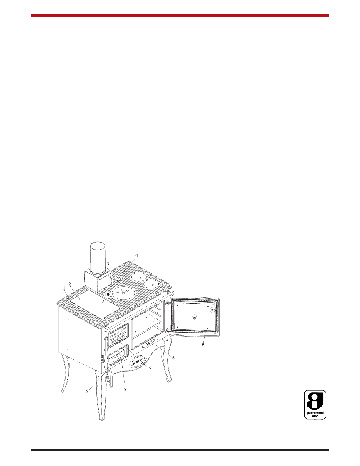
Fig.1
3
1. Hob
2. Hotplate
3. Bonnet Door
4. Direct Damper
5. Oven Door
6. Base Cleaning Door
7. Fire Fence
8. Ash Pan
9. Spin Valve
10. Oven Damper
Page 5
It is the Users/Installers responsibility to ensure that
the necessary personal protective clothing is worn
when handling materials that could be interpreted as
being injurious to health and safety. When handling
Firebricks, Fire Cement or Fuels, use disposable
gloves. Exercise caution and use disposable masks
and gloves when handling glues and sealants. When
working with fibre glass, mineral wool, insulation
materials, ceramic blanket/board or kerosene fuel
oil, avoid inhalation as it may be harmful. Avoid contact with skin, eyes, nose and throat. Use disposable
protection. Installation should be carried out in a well
ventilated area.
Handling
Adequate facilities must be available for loading,
unloading and site handling.
Fire Cement
Some types of fire cement are caustic and should
not be allowed to come into contact with the skin. In
case of contact with the skin wash immediately with
plenty of water.
Asbestos
This cooker contains no asbestos. If there is a possibility of disturbing any asbestos in the course of
installation then please seek specialist guidance and
use appropriate protective equipment.
Metal Parts
When installing or servicing this cooker care should
be taken to avoid the possibility of personal injury.
CONTROL OF SUBSTANCES
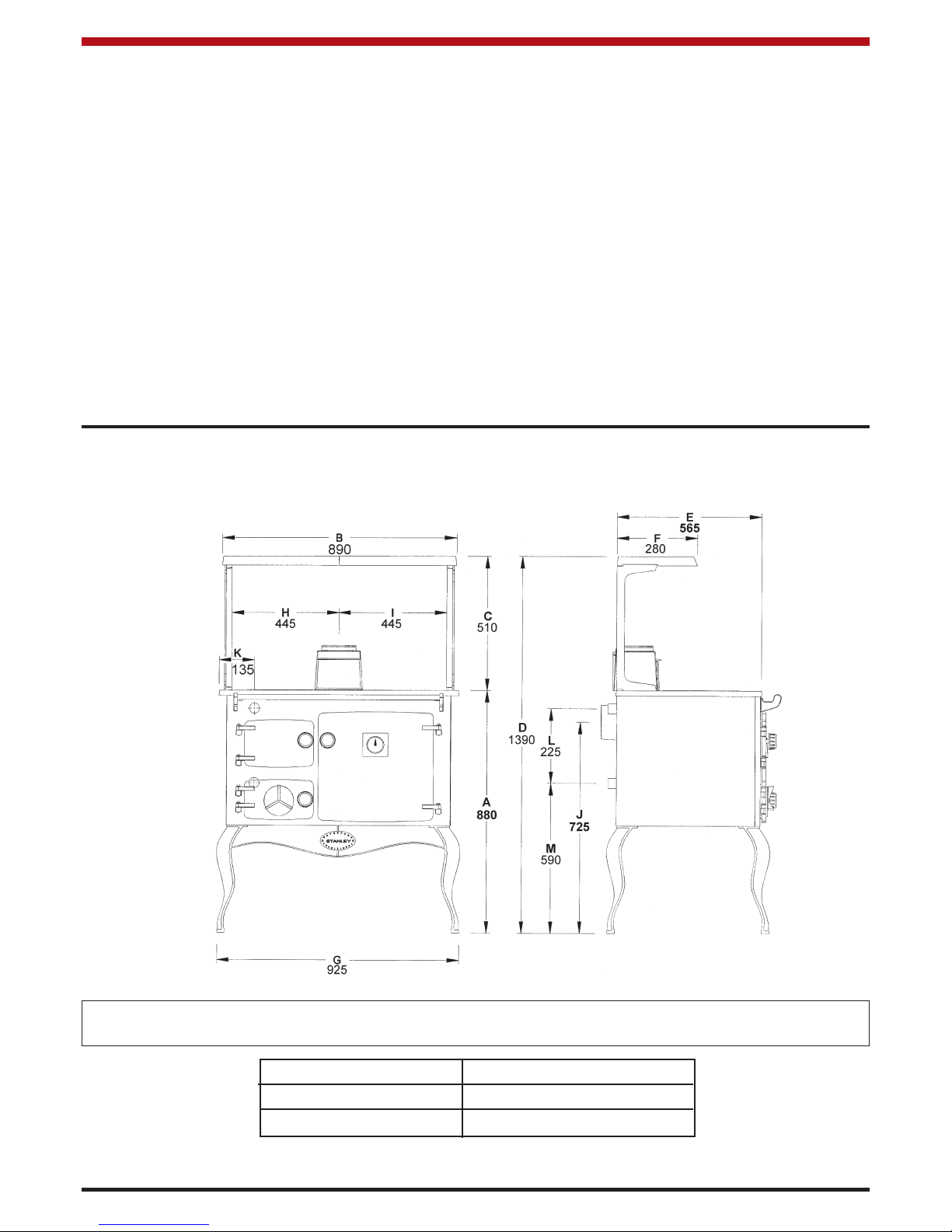
Fig.2
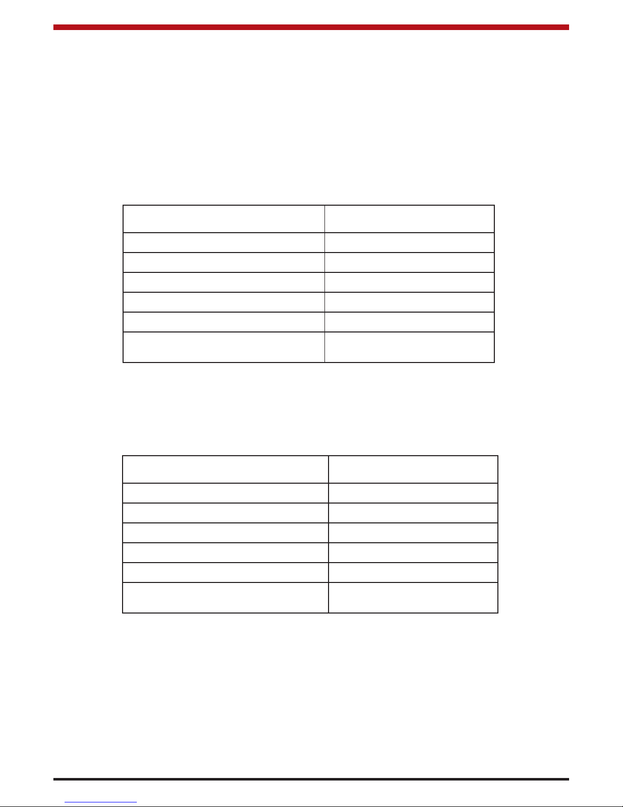
SPECIFICATION
Note: Dimensions stated are in millimetres unless otherwise stated and may be subject to a slight +/-
variation.
FEATURE METRIC
HOT PLATE 911.25 cm
2
OVEN 400W x 330H x 400D
4
Page 6
TECHNICAL DATA
CHIMNEY DRAUGHT: 15 pa.
FLUE DIAMETER: 5” (127mm)
BOILER TAPPINGS: 1” BSP (28mm)
TEST PRESSURE OF BOILER (Where applicable): 40 PSI (2.75 Bar)
COOKER WEIGHT: 263 Kgs (579 lbs)
SPACE HEATING: 5 kW’s (17, 000) Btu’s
All technical data are taken under laboratory conditions and may vary in use, flue draught conditions will effect
performance
5
47K
Nominal Outputs - Manufactured smokeless fuels kW:
High output cannot be maintained unless fuel is being burned at the above rates. The output for wood will be
lower owing to the lower calorific value of the fuel.
Nominal Outputs - Wood Fuel kW:
Typical refuelling intervals to obtain nominal
outputs
2 hours 4 kgs
Nominal heat output to space 4.5kW Nominal heat output to water 7.5 kW
Flue gas mass flow 9.0 g/s
Flue gas temp at nominal output
293
o
C
Gross Weight 263 kgs Boiler Capacity 7.5 Litres
Flue outlet 127 mm
This appliance has been tested in accordance
with BS EN 13240
Flue draught 15 Pascals
Typical refuelling intervals to obtain nominal
outputs
1 hours 4 kgs
Nominal heat output to space 5.7 kW Nominal heat output to water 5.4 kW
Flue gas mass flow 10.4 g/s
Flue gas temp at nominal output
279
o
C
Gross Weight 263 kgs Boiler Capacity 7.5 Litres
Flue outlet 127 mm
This appliance has been tested in accordance
with BS EN 13240
Flue draught 15 Pascals
Page 7

1. Remove packing strip from the top of the range.
Place the sheet steel back plate to one side.
Remove all loose components from the top of
the range and firebox and the oven. Remove
the oven door. Spread the components on
the floor so you can identify them easily.
6
Fig.3
Fig.4
PRE-INSTALLATION ASSEMBLY
When installing, operating and maintaining a solid fuel heater, respect basic standards of fire safety. Read
these instructions carefully before commencing the installation. Failure to do so may result in damage to persons and property. Consult your local municipal office, Fire Department and your insurance representative to
determine what regulations are in force.
Any permanent electrical installations made during the installation of the heating system must be done
by a registered competent electrician and in accordance with the current issue of BS 7671.
INSTALLATION
2. Place strong supports about 458mm (18”)
high behind the range. Space the supports
behind it and lay the cooker on its back.
(See Fig.4)
1. Hob Sealing Plate
2. Riddling/Operating Tool
3. Base Cleaning Door
4. Towel Rail Bracket LH
5. Towel Rail Bracket RH
6. Leg (4)
7. Plinth (RHS)
8. Plinth (LHS)
11. Nameplate
14. Ashpan
15. Oven Shelf (Sheet Iron)
22. Ashpit Door
23. Oven Door
24. Fire Door
25. Bonnet
30. Fire Fence
45. Plinth Joining Clip
46. Simmering Plate
47. Cleaning Cups (2)
48. Hotplate
49. Oven Damper
59. Oven Shelf (Cast Iron)
61. Cleaning Brush
62. Poker
63. Scraper
64. Towel Rail
71. Bonnet Door
72. Bonnet Ring
ASSEMBLY
3. Fit the four legs (Part no. 6) to the four base
corners (Part no. 52) using the hexagon-head
bolts and washers. Note that each of the front
legs has a screw hole in the front.
4. Lift the range off the supports. Stand it upright
without putting any strain on the legs.
5. Join the two sections of the front plinth together (Part No. 7 and 8) by screwing the name
plate (Part No. 11) and the plinth joining clip
(Part No. 45) into position between the two
sections and secure the two sections tightly to
the name plate.
6. Fit the complete plinth under the front of the
range inside the front legs using a screw and nut
to secure it to each leg. (See Fig.5)
7. Move the range into position for installation.
CAREFUL: Do not break a leg! Consult the
Chimney & Location Sections before finalising
the position for the range.
Page 8

Fig.5
8. Place the oven damper in position (Part No.49)
on top of the oven and place the simmering
plate (Part No.46) in position above it. Place
the oblong hotplate (Part No.48) and the two
round cleaning cups (Part No.47) in position to
complete the cooker top.
9. Place the bonnet (Part No.25) in position and fit
its front cleaning door (Part no.71) in position.
10. Screw the towel rail brackets (Part Nos.4 and
5) to the top front of the range (Part No.10)
and fix the towel-rail (Part No.64) in position
between the brackets. Tighten up the screws.
11. Hang the fire door (Part No.24) and the ashpit
door (Part No.22) on their hinges.
12. Place the oven shelves in position (Part No.15 &
59) the cast iron shelf below the sheet steel
shelf.
13. Place the base cleaning door (Part No.3) in
position beneath the oven door (Part No.23).
14. Screw the optional splashback (A) to its two
supports (B) keeping the folded end to the
bottom. Screw the platerack (C) to the splashback. Screw the complete assembly on to the
cooker hob (Part No.9). (See Fig.8)
Note: The Platerack and splashback are an
optional extra, not supplied as standard.
TOP FLUE EXIT
With the bonnet (Part No 25) in position on the hob,
connect the bonnet ring (Part No 72) onto the top of
the bonnet. The flue pipe is then connected to the
bonnet ring as shown in Fig.6. Seal all joints using
approved fire cement, ensuring that no cement
blocks the flue passageway.
Fig.6
REAR FLUE EXIT
Replace the bonnet (Part No.25) with the hob sealing plate (Part No.1), using approved fire cement to
seal the hob sealing plate to the hob. Remove the
back sealing plate (Part No.37) and fit the rear outlet spigot (Part No.29) to the flue back (Part No.36).
Connect the flue pipe to the rear flue spigot (see Fig
7). Seal all joints with fire cement ensuring that no
cement blocks the flue passageways.
Fig.7
Fig.8
7
Page 9

8
FLUES
The flue pipe must be fitted with a cleaning access.
The flue and chimney must be inspected at least
twice annually and cleaned when necessary. During
periods of non-use, the flueway through the appliance should be ventilated. By leaving the spinwheel
or ashdoor open, this will prevent the build up of
condensation.
The position of all flues and chimneys must comply
with Building Regulations.
FLUE PIPES
A flue pipe should only be used to connect an appliance to a chimney and should not pass through any
roof space.
Flue pipes may be of any of the following materials:
(a) Cast iron as described in BS 41:1973 (1981)
(b) Mild steel with a wall thickness of at least
3mm.
(c) Stainless steel with a wall thickness of at least
1mm and as described in BS EN 10095:1999
specification for stainless and heat resisting
steel plate, sheet and strip, for grade 316 S11,
316 S13, 316 S16, 316 S31, 316 S33, or the
equivalent Euronorm 88-77 designation.
(d) Vitreous enamelled steel complying with
BS 6999: 1989.
FLUE CLEANING
The flue pipe must be fitted with a cleaning access.
the flue and chimney must be inspected at least
twice annually and cleaned when necessary. During
periods of non-use, the flueway through the appliance should be ventilated. By leaving the spinwheel
or ashdoor open, this will prevent the build up of
condensation.
CHIMNEY
The Waterford Stanley Solid Fuel Range must be
connected to a Factory-Built Chimney, installed in
accordance with the manufacturer’s instructions or a
lined masonry chimney, acceptable to the authority
having jurisdiction. An existing masonry chimney
should be inspected and if necessary repaired by a
competent mason or be relined using an approved
relining system.
THE CHIMNEY SERVING THIS WATERFORD
STANLEY SOLID FUEL RANGE SHOULD NOT
SERVE ANY OTHER APPLIANCES. If you intend
to use a fireplace chimney, the fireplace opening
must be sealed. The overall height of the chimney,
measured from the floor on which the Range is
installed must be at least 4.572 meters (15ft).
Do not use more than two elbows.
Chimneys for use with solid fuel appliances should
be capable of withstanding a temperature of 1100oC
without any structural change which would impair
the stability or performance of the chimney.
Chimney’s should be built in accordance with BS EN
15287-1:2007, Design, installation and commissioning of chimney.
USE OF EXISTING FLUES AND CHIMNEYS
The spigot of this appliance will accept a 5” flue pipe.
Stanley cast iron pipes are highly recommended for
interior use. When connecting to an existing chimney it is necessary to line the flue using either 6”
(150mm) rigid or flexible stainless steel flue liner. It
is not premitted to reduce the diameter of the connecting pipe to less than the appliance outlet
between the appliance and the chimney.
An existing flue pipe or chimney that has proved to
be satisfactory when used for solid fuel can normally be used for this appliance provided that its construction, condition and dimensions are acceptable.
Flues that have proven to be unsatisfactory, particularly with regard to down draught, must not be considered for venting this appliance until they have
been examined and any faults corrected. If there is
any doubt about an existing chimney, a smoke test
should be carried out.
Before connecting this appliance to a chimney or
flue pipe which has previously been used with
another fuel, the chimney or flue pipe must be thoroughly swept and/or lined accordingly.
All register plates, restrictor plates and dampers etc.
which could obstruct the flue at a future date must
be removed before connecting this appliance.
The combustion products from this appliance will
have a descaling effect on hardened soot deposits
left from burning solid fuels.
ALTHOUGH THE CHIMNEY MAY HAVE BEEN
CLEANED OF LOOSE SOOT PRIOR TO INSTALLATION, IT IS IMPERATIVE THAT THE CHIMNEY
IS INSPECTED FOR SCALED SOOT PARTICLES
AFTER THE FIRST MONTH OF OPERATION AND
ANY LOOSE MATERIALS REMOVED TO AVOID
BLOCKAGE.
Page 10

LOCATION
There are several conditions to be considered in
selecting a location for your Waterford Stanley Solid
Fuel Range.
a. Position in the area to be heated - central
locations are usually best.
b. Allowances for proper clearances to com-
bustibles.
FLOOR PROTECTION
When installing the Waterford Stanley Solid Fuel
Range on a combustible floor, a floor protector consisting of a layer of non-combustible material at least
3/8” (9mm) thick, or of at least 1/4” (6mm) thick covered with a 1/8” (3mm) sheet of metal is required to
cover the area under the heater and to extend to at
least 18” (460mm) at the front and 8” (200mm) to the
sides and back of stove. This will provide protection
from sparks and embers which may fall out from the
door when stoking or refuelling.
Fig.9
(200mm)
(200mm)
(200mm)
(460mm)
Additional insulation must also be fitted to the wall to
protect the area around the flue and flue box. The
insulation must reach a minimum distance of
150mm either side of the flue/flue box and follow the
line of the flue. The minimum specification for this
material is Superwool 607 LTI with a density of
320kg/m3, a thickness of 10mm and a self finish.
There must be a minimum 16mm air gap between
the insulation board and an adjacent combustible
wall surface. A higher specification material maybe
used but the air gap must be maintained.
CLEARANCES TO COMBUSTIBLES
Maintain at least the following clearances to all
combustible material:
Front 460mm
Back 250mm
Oven Side 60mm
Oven Side with
Optional Shelf Fitted 60mm
Firebox Side 60mm
The minimum clearance to non-combustible materials should be maintained at least 50mm (2”) from the
back of the range.
Never obstruct free air circulation from around the
cooker. Where the flue passes through a combustible material a twin wall solid packed insulated
chimney connector must be used and come flush
with the outer surface material and run all the way to
the masonry chimney or to the point of termination
of the factory made chimney. (see Fig. 10).
Fig.10
VENTILATION & COMBUSTION AIR
REQUIREMENTS
It is imperative that there is sufficient air supply
to the cooker in order to support correct combustion.
Never cover or close air vents
The air supply to this appliance must comply with
B.S. 8303: Part 1 and Building Regulations.
The minimum effective air requirement for this appliance is 65cm
2
for both 47K and 30K models. If flue
is fitted with a flue draught stabaliser, the air requirement needs to be increased to 83cm2. When calculating combustion air requirement for this appliance
use the following equation: a total free area of at
least 550mm
2
per kW of rated output above 5kW
shall be provided. Where a flue draught stabiliser is
used the total free area shall be increased by
300mm
2
for each kW of rated output. If there is
another appliance using air fitted in the same or
adjacent room, it will be necessary to calculate additional air supply.
All materials used in the manufacture of air vents
should be such that the vent is dimensionally stable
and corrosion resistant.
The effective free area of any vent should be ascertained before installation. The effect of any screen
should be allowed for when determining the effective
9
Page 11

10
free area of any vent. Air vents direct to the outside
of the building should be located so that any air current produced will not pass through normally occupied areas of the room.
An air vent outside the building should not be located less than the dimensions specified within the
Building Regulations from any part of any flue terminal. These air vents must also be fire proofed as per
Building Regulations.
Air vents in internal walls should not communicate
with bedsits, toilets, bathrooms or rooms containing
a shower.
Air vents traversing cavity walls should include a
continuous duct across the cavity. The duct should
be installed in such a manner as not to impair the
weather resistance of the cavity.
Joints between air vents and outside walls should be
sealed to prevent the ingress of moisture. Existing
air vents should be of the correct size and unobstructed for the appliance in use.
ITS NOT RECOMMENDED FOR AN EXTRACTION
FAN TO BE FITTED IN THE SAME ROOM AS
THIS APPLIANCE BUT IF THERE IS AN EXTRACTOR FAN SHOULD NOT BE FITTED IN THE
SAME ROOM AS THIS APPLIANCE. IF THERE IS
AN AIR EXTRACTION FAN FITTED IN THE ROOM
OR ADJACENT ROOMS WHERE THIS APPLIANCE IS FITTED, ADDITIONAL AIR VENTS WILL
BE REQUIRED TO ELEVIATE THE POSSIBILITY
OF SPILLAGE OF PRODUCTS OF COMBUSTION
FROM THE APPLIANCE/FLUE WHILE THE FAN
IS IN OPERATION.
Where such a installation exists, a test for spillage
should be made with the fan or fans and other appliances using air in operation at full rate, (i.e. extraction fans, tumble dryers) with all external doors and
windows closed.
If spillage occurs following the above operation, an
additional air vent of sufficient size to prevent this
occurrence should be installed.
SMOKE SPILLAGE TEST
In all installations a spillage test should be carried
out to ensure there is sufficient combustion and the
flue system is adequate.
The spillage test is carried out as follows:
1. Light/burn appliance under normal conditions in accordance with this installation
manual.
2. Close all doors and windows.
3. Operate all appliances requiring air at full
rate (eg. extraction hoods, tumble dryers
etc).
4. Check for smoke spillage.
PLUMBING
Diagrams illustrate the basic principles of water systems and are not to be regarded as working drawings.
Fig. 11
NOTE: We strongly advise the use of pipe lagging
and also the use of a frost thermostat if the installation is likely to be exposed to situations where the
temperatures will drop to a level consistent with
frost.
Central Heating and Indirect Domestic Hot
Water.
Recommended indirect cylinder 135 litres, depending on domestic requirements with a 28mm flow and
return pipes not exceeding 7.8m each in length.
Cylinder and pipework should be lagged to minimise
heat losses.
HEATING SYSTEM
The system must include a gravity circuit with
expansion pipe, open to the atmosphere. The central heating must be pump-driven as with other types
of boilers. The primary air valve controls the heating
rate of the boiler, Closed = minimum, Open = maximum output. (See operating instructions).
The central heating system must be designed and
installed in accordance with the following standards:
BS EN 14336:2004: Heating Systems in Buildings.
Installation and commissioning of water based
Page 12

11
heating systems. BS EN 12828: 2003; Heating
Systems in Buildings. Design of water based heating
systems. BS EN 12831: 2003; Heating Systems in
Buildings. Method for calculation of the design heat
load.
GRAVITY CIRCUIT
The gravity circuit consists of a domestic hot water
tank of 135 litres. An indirect cylinder to BS 1566
must be used. A heat leak radiator with a heat output minimum 1kW should also be connected on the
gravity circuit. It should be connected to the boiler
by 28mm diameter flow and return piping. The pipes
should not exceed 7.8m each in length and anything
in excess of 4.6m must be fully lagged. The shorter
the run of pipe work the more effective the water
heating efficiency and to this end, the cylinder
should be fully lagged. In the interest of safety do
not have any valves on this circuit. It is recommended to fit a drain point at the lowest level of the
system and at any point that may not drain if the system is emptied.
HEATING
Care should be taken to ensure that the heating
installation is correctly installed and that it complies
with all relevant codes of practice. If this appliance
is being connected to an existing system, it is
strongly recommended to check the following.
(a) That the pipework is adequately insulated
(where applicable).
(b) Check all controls e.g. pump, pipe thermostat
etc, are operating satisfactorily and are compatible with the requirements of the cooker.
(c) Cleanse the system and add suitable inhibitor.
Only competent personnel should be employed to
carry out your heating installation.
PIPE FITTINGS
Materials used for installation work should be fire
resistant, sound and should conform to the current
editions of the following or their equivalent:
1. Ferrous Materials
B.S. 1387: Steel tubes
B.S. 1740: Steel pipe fittings
B.S. 5295 & jointing materials
2. Non-ferrous materials
I.S. 238: Copper tubes
B.S. 4127: Stainless steel tubes
EN 29453:Solder
I.S. 239: Compression tube fittings
B.S. 1552: Manual shut-off valves
WATER CIRCUIT TEMPERATURE
The return water temperature must be maintained at
not less than 50º C so as to avoid condensation on
the boiler and return piping. Fitting a pipe thermostat to the return from the gravity circuit and wiring it
into the pump control will ensure than no cold water
will be returned from the central heating circuit
before the water from the gravity circuit has warmed
up the common return pipe and boiler. If this is not
sufficient to keep the boiler temperatures above the
required minimum, a three-way mixing valve may be
fitted to the flow pipe to divert some hot water
straight back into the return. Such a valve can be
operated either manually or electrically in conjunction with a return pipe thermostat.
In some circumstances it may be possible to overheat the appliance and the water inside will boil. This
will be evident by the sound of a knocking noise
coming from the appliance and pipes around the
house. If this occurs close off all air controls and
manually start the central heating pump if fitted.
One radiator on the heating circuit should be uncontrolled to act as a heat leak in the event that the
appliance overheats and has nowhere to discharge
a build up of hot water should the heating circuit be
satisfied. Be aware that steam and boiling water will
be expended from any open vent from the heating
system probably in the roof space at the expansion
tank.
In the unlikely event that the appliance is not operating in freezing conditions the water must be
drained from the boiler to prevent frost damage.
Fig.12
COMMISSIONING & HANDOVER
Ensure all parts are fitted in accordance with the
instructions.
On completion of the installation allow a suitable
period of time for any fire cement and mortar to dry
out, before lighting the stove. Once the stove in
under fire check all seals for soundness and that the
boiler and water system are operating correctly.
Page 13

12
Ensure that the flue is functioning correctly and that
all products of combustion are vented safely to
atmosphere via the chimney terminal.
On completion of the installation and commissioning
ensure that the operating instructions for the cooker
are left with the customer. Ensure to advise the customer on the correct use of the appliance with the
fuels likely to be used on the cooker and warn them
to use only the recommended fuels for the cooker.
Advise the user what to do should smoke or fumes
be emitted from the cooker. The customer should be
warned to use a fireguard to BS 6539 in the presence of children, aged and/or infirm persons.
CARE FOR YOUR CENTRAL HEATING SYSTEM
We strongly recommend the use of suitable corrosion inhibitors and anti-freeze solution in your heat
ing system, in an effort to minimise black oxide,
sludge and scale build-up, which effects efficiency.
In hard water areas the use of a suitable limescale
preventer / remover is advised.
Use only quantities specified by the water treatment
product manufacturer. Only add to the heating system after flushing and finally refilling. Refer to BS
7953.
INJECTOR TEE (Central Heating)
Where the gravity and central heating circuits join
together to return to the Cooker we recommend the
use of an injector tee connection, situated as close
to the unit as possible. This type of tee encourages
a stable flow of hot water through both circuits and
helps to prevent priority being given to the stronger
flow, which is most commonly the pumped central
heating circuit. This way, there will be no shortage
of hot water to the taps when the heating is on.
Fig.13
ing under doorways that may not be possible to
drain.
GENERAL MAINTENANCE
It is important that the user is familiar with their heating system and that they ensure regular checks and
maintenance which can limit unnecessary breakdowns.
We recommend that you evaluate the overall insulation in your house, i.e. attic, external walls, windows,
external doors. Insulation and draught proofing can
greatly reduce running costs, while equally enhancing living conditions.
FUELS
This appliance has been tested using manufactured
briquetted smokeless fuel (Ancit) for closed appliances, sized between 20g and 140g and seasaoned
wood logs. Other fuels are commercially available
and may give similar results. All fuels should be
stored under cover and kept as dry as possible
before use.
Do not use fuels with a Petro-coke ingredient as this
may cause the grate to overheat, causing damage.
Reduced outputs will result when fuels of lower
calorific values are used. Never use gasoline or
gasoline type lantern fuel, kerosene, charcoal lighter
fluid or similar liquids to start or freshen up a fire in
this heater. Keep all such liquid well away from the
heater at all times. Operate the stove only with the
fuelling door closed except for re-fuelling.
This appliance has obtained HETAS Ltd approval as
a ‘continuous’ operating appliance for burning manufactured briquetted smokeless fuel as the recommended fuel, it also has approval as an intermittent
operating appliance for burning wood logs. HETAS
Approval does not cover the use of other fuels either
alone or mixed with the recommended fuel, nor does
it cover instructions for the use of other fuels.
WARNING NOTE
Properly installed, operated and maintained this
stove will not emit fumes into the dwelling.
Occasional fumes from de-ashing and re-fuelling
may occur. However, persistent fume emission is
potentially dangerous and must not be tolerated. If
fume emission does persist, then the following
immediate action should be taken -
(a) Open doors and windows to ventilate room.
(b) Let the fire out or eject and safely dispose of
fuel from the stove.
DRAINING
Key - operated drain taps to B.S. 2879 should be
provided in accessible positions in all low parts of
the system. However it should be noted that there
may be short sections of pipework e.g. when pass-
Page 14

13
(c) Check for flue or chimney blockage and clean if
required.
(d) Do not attempt to relight the fire until the cause
of the fume emission has been identified and
corrected. If necessary seek expert advice.
The most common cause of fume emission is flueway or chimney blockage. For your own safety
these must be kept clean at all times.
FUEL CALORIFIC VALUES
Anthracite 25-50mm C.V.: 8.2 kW/Kg = 14,000 Btu’s/lb
House Coal 25-75mm C.V.: 7.2 kW/Kg = 12,300 Btu’s/lb
Peat Briquettes C.V.: 4.8 kW/Kg = 8,300 Btu’s/lb
REFUELLING
Before refuelling the range, open the direct damper
(Part No.51). Add the fuel, and after refuelling
ensure that the direct damper is closed, otherwise
oven temperature will drop and the fire box may
overheat.
Note: Only the recommended fuels as outlined in
the section on fuels may be used during refuelling of
the range.
CONTROLLING THE FIRE
The direct damper must be kept closed except when
initially lighting the fire or during refuelling. The burn
rate is adjusted by controlling the primary air using
the spin valve. The primary air is increased by turning the spin valve anticlockwise, and decreased by
turning it clockwise (see Fig.14). The oven damper
under the round hot plate controls the chimney
draught which also adjusts the burn rate. (see
Fig.15). For normal running leave the oven damper
in the open position. It may be necessary to close
the damper to assist with overnight burning or in
conditions of excessive flue draught. It is possible to
direct more heat to water and less to the oven by
opening the direct damper and closing the oven
damper.
Fig.14
Fig.15
You will get to know how to use the spin valve and
oven damper in conjunction for the optimum range
performance. Ensure that both the ashpit door (Part
No.22) and the fire door (Part No.24) are closed
securely during firing. Opening the spinwheel 2-3
turns for mineral fuels and 3-4 turns for wood logs is
a good starting point to understand the operation of
the cooker.
KEEP ALL COMBUSTIBLE MATERIALS AT
LEAST 1220mm (4 Feet) AWAY FROM THE
RANGE. They include rugs, fabrics, furnishings,
papers, firewood, etc. NEVER dry clothing on or
within 1220mm (4 Feet) of the range.
OVERNIGHT BURNING
Open the spin valve (Part No.73) by a quarter turn
and close the oven damper (Part No.49); riddle the
fire and refuel. In the morning open the air valve and
damper and riddle the fire; when it is again burning
brightly, refuel. If it is found that the fire is completely burned out then new settings should be tried
in respect of the spin valve. On the other hand if the
fire is out and the fuel unburned then the reverse
should apply.
DE-ASHING
The ash pan (Part No. 14) must be emptied regularly, otherwise ash will build up to a point where it
interferes with the natural flow of cool air through the
fire bars and as a consequence these will be damaged.
The ashpan is accessed by opening the ashpit door
(Part No.22) and is removed using the riddling tool
(Part No.2).
Note: The ashpan must be replaced in position
before the range is fired.
DISPOSAL OF ASHES
Ashes should be placed in a metal container with a
tight-fitting lid. The closed container of ashes should
be placed on a non-combustible floor or on the
ground well away from all combustible materials
Page 15

pending final disposal. If the ashes are disposed of
by burial in soil or otherwise locally dispersed they
should be retained in the closed container until all
cinders have thoroughly cooled.
MAIN OVEN
When baking or roasting, open the oven damper
and spin valve fully until the thermometer shows a
temperature about 20
o
F (10oC) higher than that
which is required. Then close the Spin Valve to a
point where the required temperature is sustained (a
little practice will soon show how much adjustment is
necessary). Much will also depend on the strength
of the chimney draught. Remember the direct flue
damper must be kept fully closed as a by-pass is
provided to allow waste gases through at all times.
When baking or roasting, if it is found that the surface of the food is cooking too quickly then position
the plain steel shelf in the top of the oven so as to
act as a heat shield which will protect the food on the
shelf beneath.
THE HOTPLATE
Use the hotplate and the cooking-top of the range
for boiling simmering, frying, grilling, braising, etc.
(Hotter side is to the left) Best results can be
obtained by using flat bottomed utensils. The lacquer which was applied to protect the surfaceground hotplates will burn off and give a strong
odour during the burn off process. Keep the hotplates clean with a wire brush. Over a short period
you will quickly adapt to the best ways and means of
using the cooker-top in order to obtain utmost satisfaction and efficiency.
14
USE OF TOOLS
Fig.17
Ash Pan
Lifting Tool
Soot
Cleaning
WARNING! THIS APPLIANCE IS HOT WHILE IN
OPERATION, USE TOOLS PROVIDED WHEN
ADJUSTING CONTROLS.
DO NOT HEAT UP SEALED OR UNOPENED
CONTAINERS OF FOOD.
DO NOT USE AEROSOL SPRAY NEAR THE
COOKER WHEN IT IS ALIGHT.
CAUTION! IF USING A DEEP FAT FRYER ON
THIS APPLIANCE, NEVER LEAVE THE FRYER
UNATTENDED AND NEVER ATTEMPT TO
EXTINGUISH A FIRE USING WATER. PLACE A
SOAKED TOWEL OVER THE TOP OF THE PAN
TO EXTINGUISH FLAMES AND REMOVE PAN
FROM SOURCE OF HEAT.
IF IN ANY DOUBT IMMEDIATELY EVACUATE
THE BUILDING AND CALL THE FIRE BRIGADE.
OVER-FIRING
When using anthracite, coke or coal avoid excessive
firing conditions. High temperatures are unnecessary and can only do serious harm to the cooker.
The first indication that overheating is taking place
will be the formation of Clinker (Melted Ash) in the
firebox and this should be removed immediately otherwise damage will occur not only to the cooker
components but also to the fire bricks and any damage here should be repaired without delay.
HINTS ON FIRE SAFETY
To provide reasonable fire safety the following
should be given serious consideration:
1. The installation of smoke detectors.
2. A conveniently located Class A fire extinguisher.
3. A practical evacuation plan.
4. A plan to deal with chimney fire as follows
(a) Notify the fire department
(b) Prepare occupants for immediate
evacuation.
(c) Close all openings into the stove
(d) While awaiting fire department, watch for
ignition of adjacent combustibles from over-
heated stove pipe or hot embers or sparks
from the chimney.
NOTE: Inspect the chimney flue weekly until a safe
frequency is established.
Page 16

15
LIGHTING THE FIRE
Before lighting the appliance:
* Check with the installer that the installation work and commissioning checks described in the
installation instructions have been carried out correctly and that the chimney has been swept
clean, is sound and free from any obstructions.
* As part of the commissioning and handover procedure the installer should demonstrate how to
operate the appliance correctly.
* Check water system is not frozen.
1. Open the Fire Door.
2. Lower Fire Fence by lifting up and then tilt forward. Fuel may also be loaded through the opening hotplate.
3. Open the Spin Valve fully by rotating it in an anit-clockwise direction. Turn the direct damper to open by
using the operating tool.
4. Kindle with paper and sticks in the usual way.
5. Ignite by using a taper or rolled wad of paper.
6. Lift up the fire fence and close the fire door.
7. Under no circumstances should any flammable liquid i.e. petrol, paraffin etc., be used to light the
fire.
8. When the fire is well established, and the flue is warm, close the direct damper fully and keep it closed.
9. Add fuel to the firebox as required and adjust the spin valve to suit the current requirements.
Note: It is also possible to access the firebox by lifting the hotplate. (See Hotplate Section).
IMPORTANT: UNDER NO CIRCUMSTANCES SHOULD ANY FLAMMABLE LIQUID, GASOLINE
KEROSENE, LIGHTER FLUID OR CHARCOAL- STARTERS BE USED TO LIGHT OR “FRESHEN UP” THE
FIRE. “KEEP ALL SUCH LIQUIDS WELL AWAY FROM STOVE (COOKER) WHILE IN USE”
THIS APPLIANCE IS HOT WHILST IN OPERATION, KEEP CHILDREN, CLOTHING AND FURNITURE A
SAFE DISTANCE AWAY.
OPERATE APPLIANCE ONLY WITH FUELLING DOOR AND ASHPIT DOOR CLOSED.
Page 17

Remove the hotplate & simmering plate (Part No.48
& 9), the bonnet door (Part No.25), the oven damper
(Part No.49) and the cleaning cups (Part No.47)
from the top of the cooker. See Fig. 18. If the flue
is connected to the back outlet configuration, the
hob sealing plate (Part No.1) is removed instead of
the bonnet door.
To remove all the accumulated deposits, take off the
cleaning door (Part No.3) situated immediately
under the oven on the front of the cooker and thoroughly clean out the residue from the side flue, back
flue and base plate using the scraper tool (Part No.
63). This operation is essential, otherwise the flow
of combustion gases will be obstructed or even
stopped, and satisfactory oven temperature will not
be maintained, apart from which such deposits will
cause smoking. See Fig.21.
Replace all loose parts which have been removed
making sure that all cooking surfaces have been
thoroughly cleaned on the underside. See Fig.22. It
is important to replace the cleaning door and to
make sure it is sealed tight. Failure to do so will
impair oven performance.
CLEANING INSTRUCTIONS
Fig.18
Fig.20
Fig.21
All deposits from the flue pipe and the top of the
oven may be brushed both into the firebox and down
the back flue passage way. See Fig. 19.
Deposits which have accumulated on the side of the
oven must also be brushed downward. (See Fig 20)
16
Direct Damper
Open
Cleaning
Brush
Flue
Passageway
SIDE FLUE
PASSAGEWAY
Fig.19
Page 18

17
3. Use only products recommended by the
Vitreous Enamel Association, these products
carry the Vitramel label.
4. DO NOT USE ABRASIVE PADS OR OVEN
CLEANSERS CONTAINING CITRIC ACID
ON ENAMELLED SURFACES. ENSURE
THAT THE CLEANSER MANUFACTURERS INSTRUCTIONS ARE ADHERED TO.
CO AWARENESS
Any solid fuel appliance emits carbon monoxide
which is an odourless gas. Usually this will pass
safely up the flue. If the flue is not maintained properly or in certain unusual conditions, this gas can be
spilled into the room. In a well ventilated room this
is not a problem but we advise fitting a CO monitoring device which will warn householders of the presence of high levels of Carbon Monoxide and will
allow corrective action to be taken in good time.
These items can be purchased locally and are about
the size and cost of a smoke alarm.
People affected by CO poisoning may have one or
any of the following symptoms:-
Headaches, Nausea (sickness), Drowsiness or ‘Flu
like’ symptoms. The elderly and young are particularly at risk and may show the effects first.
Preventative action should include :-
* Regularly checking the appliance and flue for
blockage,
* Having the appliance regularly serviced by a
competent person,
* Making sure vents and grilles are not blocked or
obstructed
* Fitting a CO alarm.
CHIMNEY FIRES
Failing to maintain your cooker properly can lead to
a chimney fire. Chimney fires occur when combustible deposits on the inner walls of the chimney
ignite. These combustible deposits, called “creosote” are a natural by-product of woodburning. A
fire hazard exists if
1
/4” of creosote (or more) coats
the inner walls of the chimney.
Association
Fig.22
CLEANING THE MILD STEEL PARTS
The steel side panels and splash back must not be
cleaned with steel wool. Use only washing up liquid
in hot water with a lint free cloth. Dry off and apply
a coat of good quality furniture polish.
CLEANING THE OVENS
Grease spillages will burn off from the oven interior,
when the oven is hot and any other loose materials
can be wiped out with a cloth, when cold. Stubborn
stains in the oven and on the shelves in the oven
can be cleaned off with a paste of bread soda and
water.
CLEANING THE HOT PLATE
The hotplate may be cleaned using a small amount
of oil or fine steel wool to remove rust and cooking
stains. Dry off with a lint free cloth and apply a light
coat of cooking oil to preserve the finish.
VITREOUS ENAMEL CLEANING
General cleaning must be carried out when the
stove is cool.
If this stove is finished in a high gloss vitreous enamel, to keep the enamel in the best condition observe
the following tips:
1. Wipe over daily with a soapy damp cloth,
followed by a polish with a clean dry duster.
2. For stubborn deposits a soap impregnated
pad can be carefully used on the vitreous
enamel.
Page 19

Prevention:
Chimney fires do not occur in clean, intact, properly
installed chimneys. Have a professional chimney
sweep clean and inspect your appliance at least
once a year. More frequent cleanings may be
required, based on the type of fuel burned, the type
of appliance, and the frequency of use. In general,
an older appliance or one that is used frequently will
require more than one cleaning per year.
Detection:
The first indication of a chimney fire is usually the
noise, a roaring sound that grows louder as the fire’s
intensity increases. Clouds of black smoke and
sparks will be seen exiting the top of the chimney, in
severe fires, flames can extend several feet above
the chimney.
Action:
Incase of a chimney fire follow these steps but do not
put yourself or others in peril:
1. Call the fire brigade immediately.
2. Get everyone out of the property.
3. Close down the air supply to the appliance i.e.
the primary air spinner and the flue damper.
Limiting the fire’s air supply will reduce its intensity. If there is a damper in the chimney connector, plug or close the opening.
4. If a fire extinguisher is available open the appliance door just enough to insert the nozzle of a
10lb dry chemical fire extinguisher rated for
Class ABC fires. Discharge the entire content of
the extinguisher into the appliance and shut the
door.
5. If possible, wet down the roof and other outside
combustibles to prevent fires ignited by shooting
sparks and flames.
6. Closely monitor all combustible surfaces near
the chimney. During severe chimney fires, these
surfaces can become hot enough to ignite.
After a chimney fire, have the chimney inspected by
a professional chimney sweep or cooker installer.
IMPORTANT: Only use replacement parts that are
authorised by the manufacturer of this appliance and
fitted by a recognised engineer. Do not make modifications that are not authorised by the manufacturer
as this may affect the safety or running of the appliance.
SPARE PARTS
Spare and replacement parts can be obtained from
your Waterford Stanley dealer or direct from the
manufacturer. Always use a qualified service/heating
engineer when servicing is required. Use only
replacement parts. Do not make unauthorised modifications.
18
Page 20

19
EXPLODED VIEW
N00076AXX DP 100803
Manufactured by
Waterford Stanley Ltd.,
Unit 210, IDA Industrial Estate, Cork Road,
Waterford, Ireland.
Tel: (051) 302300 Fax (051) 302315
www.waterfordstanley.com
1. Hob Sealing Plate - B00135BXX
2. Lifting Tool - B00140AXX
3. Front Cleaning Door - B00141AXX
4. Towel Rail Bracket RH - B00142AXX
5. Towel Rail Bracket LH - B00143AXX
6. Leg - B00144AXX
7. Plinth RH - B00145AXX
8. Plinth LH - B00146AXX
9. Errigal Machined Hob - B00151DXX
10. Front - B00152DXX
11. Name Plate - B00156AXX
12. Small Back Panel - F00056CXX
13. Angle Bracket - F00057AXX
14. Ashpan - F00058AXX
15. Oven Shelf - F00061AXX
16. Back Panel LH - F00062BXX
17. Side Panel - F00069CXX
18. Base Panel - F00071AXX
19. Fire Bar Link - F00097AXX
20. 47K Boiler - F00201EXX
21. Solid Brick - H00036AXX
22. Ash Pit Door - L00034AXX
23. Oven Door Assembly - L00058AXX
24. Fire Door - L00059AXX
25. Bonnet - B00124AXX
26. Serial Number Plate - N00234BXX
27. Summer Brick -
Q00096BXX
28. Spigot - Q00097AXX
29. Flue Outlet Connection 5” - Q00098AXX
30. Fire Bar - Q00111AXX
31. Summer Brick - Q00112AXX
32. Bottom Grate Frame - Q00114AXX
33. Ashpit Back - Q00115BXX
34. Ashpit Side RH - Q00116AXX
35. Ashpit Side LH - Q00117AXX
36. Flue Back - Q00119BXX
37. Back Sealing Plate - Q00120AXX
38. Oven Bottom - Q00121BXX
39. Oven Side RH - Q00122BXX
40. Oven Side LH - Q00125BXX
41. Oven Back - Q00128CXX
42. Flue Check - Q00129AXX
43. Hotplate Cup Clips - Q00132BXX
44. Cleaning Door Clip - Q00133AXX
45. Plinth Joining Clip - Q00134AXX
46. Simmering Plate - Q00136BXX
47. Hotplate Cup - Q00137AXX
48. Hotplate - Q00138CXX
49. Oven Flue Damper - Q00139AXX
50. Hob Protecting Plate -
Q00140AXX
51. Damper With Cut Out - Q00142AXX
52. Base - Q00146CXX
53. Fire Bar Standard - Q00148AXX
54. Shaker Bar Frame - Q00234AXX
55. Oven Top - Q00235EXX
56. Ashpit Bottom - Q00595AXX
57. Hob Protection Plate - Q00620AXX
58. Oven End Flue - Q00723BXX
59. Shelf Diffuser - Q00728AXX
60. Boiler Plug - V00016AXX
61. Cleaning Brush - V00072AXX
62. Poker - V00073AXX
63. Scraper - V00074AXX
64. Towel Rail - V00077AXX
65. Stay Rod - V00082DXX
66. Hotplate Lifter - V00086AXX
67. Wire Brush - V00093AXX
68. Steam Vent - W00904AXX
69. Stay Rod Nut - W00920AXX
70. Stay Rod Nut Cap - W00923AXX
71. Bonnet Door - B00125AXX
72. Bonnet Ring - B00147AXX
73. Spin Valve - B00128AXX
 Loading...