

Page 1
Erin Non Boiler Solid Fuel Stove
INSTALLATION AND OPERATING INSTRUCTIONS
This appliance is hot while in operation and retains its heat for a long period of time after use.
Children, aged or infirm persons should be supervised at all times and should not be allowed to touch
the hot working surfaces while in use or until the appliance has thoroughly cooled.
When using the stove in situations where children, aged and/or infirm persons are present a fireguard
must be used to prevent accidental contact with the stove. The fireguard should be manufactured in
accordance with
BS 8423:2010.
PLEASE RETAIN
Page 2

TABLE OF CONTENTS
PAGE NO.
1. Stanley Solid Fuel Stove Warranty . . . . . . . . . . . . . . . . . . . . . . . . . . . . . . . . . . . . . . . . . . . . . . . . . . 3
2. Installation Checklist . . . . . . . . . . . . . . . . . . . . . . . . . . . . . . . . . . . . . . . . . . . . . . . . . . . . . . . . . . . . . 4
3. Important Operation/ Maintenance Notes . . . . . . . . . . . . . . . . . . . . . . . . . . . . . . . . . . . . . . . . . . . .5
4. Installation & Operating Instructions . . . . . . . . . . . . . . . . . . . . . . . . . . . . . . . . . . . . . . . . . . . . . . . . ..6
5. General . . . . . . . . . . . . . . . . . . . . . . . . . . . . . . . . . . . . . . . . . . . . . . . . . . . . . . . . . . . . . . . . . . . . . . ..6
6. Pre Installation Assembly . . . . . . . . . . . . . . . . . . . . . . . . . . . . . . . . . . . . . . . . . . . . . . . . . . . . . . . . . .6
7. Pre Installation Assembly . . . . . . . . . . . . . . . . . . . . . . . . . . . . . . . . . . . . . . . . . . . . . . . . . . . . . . . . . .7
8. Flues . . . . . . . . . . . . . . . . . . . . . . . . . . . . . . . . . . . . . . . . . . . . . . . . . . . . . . . . . . . . . . . . . . . . . . . . ..8
9. Flue Pipes . . . . . . . . . . . . . . . . . . . . . . . . . . . . . . . . . . . . . . . . . . . . . . . . . . . . . . . . . . . . . . . . . . . . .8
10. Chimney . . . . . . . . . . . . . . . . . . . . . . . . . . . . . . . . . . . . . . . . . . . . . . . . . . . . . . . . . . . . . . . . . . . . . . .8
11. Chimney . . . . . . . . . . . . . . . . . . . . . . . . . . . . . . . . . . . . . . . . . . . . . . . . . . . . . . . . . . . . . . . . . . . . . . .9
12. Flue Exit - Top and Rear . . . . . . . . . . . . . . . . . . . . . . . . . . . . . . . . . . . . . . . . . . . . . . . . . . . . . . . . . .10
13. Down Draughts . . . . . . . . . . . . . . . . . . . . . . . . . . . . . . . . . . . . . . . . . . . . . . . . . . . . . . . . . . . . . . . . .11
14. Ventilation & Combustion Air Requirements . . . . . . . . . . . . . . . . . . . . . . . . . . . . . . . . . . . . . . . . . . .11
15. Location . . . . . . . . . . . . . . . . . . . . . . . . . . . . . . . . . . . . . . . . . . . . . . . . . . . . . . . . . . . . . . . . . . . . . . . 12
16. Clearance to Combustibles . . . . . . . . . . . . . . . . . . . . . . . . . . . . . . . . . . . . . . . . . . . . . . . . . . . . . . . .12
17. Floor Protection . . . . . . . . . . . . . . . . . . . . . . . . . . . . . . . . . . . . . . . . . . . . . . . . . . . . . . . . . . . . . . . . . 12
18. Stove Dimensions . . . . . . . . . . . . . . . . . . . . . . . . . . . . . . . . . . . . . . . . . . . . . . . . . . . . . . . . . . . . . . . 13
19. Commissioning & Handover . . . . . . . . . . . . . . . . . . . . . . . . . . . . . . . . . . . . . . . . . . . . . . . . . . . . . . .13
20. Operation . . . . . . . . . . . . . . . . . . . . . . . . . . . . . . . . . . . . . . . . . . . . . . . . . . . . . . . . . . . . . . . . . . . . . . 13
21. Air Controls . . . . . . . . . . . . . . . . . . . . . . . . . . . . . . . . . . . . . . . . . . . . . . . . . . . . . . . . . . . . . . . . . . . .13
22. Recommended Fuels . . . . . . . . . . . . . . . . . . . . . . . . . . . . . . . . . . . . . . . . . . . . . . . . . . . . . . . . . . . . .14
23. Technical Data . . . . . . . . . . . . . . . . . . . . . . . . . . . . . . . . . . . . . . . . . . . . . . . . . . . . . . . . . . . . . . . . . .15
24. Lighting . . . . . . . . . . . . . . . . . . . . . . . . . . . . . . . . . . . . . . . . . . . . . . . . . . . . . . . . . . . . . . . . . . . . . . . 15
25. User Instructions . . . . . . . . . . . . . . . . . . . . . . . . . . . . . . . . . . . . . . . . . . . . . . . . . . . . . . . . . . . . . . . . 15
26. De-Ashing/ Refuelling . . . . . . . . . . . . . . . . . . . . . . . . . . . . . . . . . . . . . . . . . . . . . . . . . . . . . . . . . . . .16
27. Slow Burning . . . . . . . . . . . . . . . . . . . . . . . . . . . . . . . . . . . . . . . . . . . . . . . . . . . . . . . . . . . . . . . . . . . 16
28. Disposal of Ashes . . . . . . . . . . . . . . . . . . . . . . . . . . . . . . . . . . . . . . . . . . . . . . . . . . . . . . . . . . . . . . .16
29. Monthly Maintenance . . . . . . . . . . . . . . . . . . . . . . . . . . . . . . . . . . . . . . . . . . . . . . . . . . . . . . . . . . . . 16
33. Periodic Maintenance . . . . . . . . . . . . . . . . . . . . . . . . . . . . . . . . . . . . . . . . . . . . . . . . . . . . . . . . . . . . 16
30. Door Latch Adjustment . . . . . . . . . . . . . . . . . . . . . . . . . . . . . . . . . . . . . . . . . . . . . . . . . . . . . . . . . . . 16
31. Chimney Cleaning . . . . . . . . . . . . . . . . . . . . . . . . . . . . . . . . . . . . . . . . . . . . . . . . . . . . . . . . . . . . . . 17
31. Glass Cleaning . . . . . . . . . . . . . . . . . . . . . . . . . . . . . . . . . . . . . . . . . . . . . . . . . . . . . . . . . . . . . . . . . 17
31. Vitreous Enamel Cleaning . . . . . . . . . . . . . . . . . . . . . . . . . . . . . . . . . . . . . . . . . . . . . . . . . . . . . . . . 17
31. Cleaning a Matt Black/ Senotherm Stove . . . . . . . . . . . . . . . . . . . . . . . . . . . . . . . . . . . . . . . . . . . . 17
31. Changing Rope Seals . . . . . . . . . . . . . . . . . . . . . . . . . . . . . . . . . . . . . . . . . . . . . . . . . . . . . . . . . . . 17
34. Prolonged Periods of Non Use . . . . . . . . . . . . . . . . . . . . . . . . . . . . . . . . . . . . . . . . . . . . . . . . . . . . . 17
35. Fire Safety . . . . . . . . . . . . . . . . . . . . . . . . . . . . . . . . . . . . . . . . . . . . . . . . . . . . . . . . . . . . . . . . . . . . . 18
36. Glass Replacement . . . . . . . . . . . . . . . . . . . . . . . . . . . . . . . . . . . . . . . . . . . . . . . . . . . . . . . . . . . . . .18
36. Replace Damaged Bricks . . . . . . . . . . . . . . . . . . . . . . . . . . . . . . . . . . . . . . . . . . . . . . . . . . . . . . . . .18
37. CO Alarm . . . . . . . . . . . . . . . . . . . . . . . . . . . . . . . . . . . . . . . . . . . . . . . . . . . . . . . . . . . . . . . . . . . . . . 19
38. Exploded View . . . . . . . . . . . . . . . . . . . . . . . . . . . . . . . . . . . . . . . . . . . . . . . . . . . . . . . . . . . . . . . . ..20
2
Page 3
3
STANLEY SOLID FUEL STOVE WARRANTY
CONDITIONS OF WARRANTY
Your Stanley Solid Fuel Stove is guaranteed against any part that fails (under normal operating conditions) as detailed
in the following table with timelines specified from the date of installation of the appliance. If the unit is not installed with-
in six months of date of purchase, the warranty will commence six months from the date of purchase.
Warranty Period Parts Covered (Parts & Labour unless Stated)
Up to 1 Year • Refractory materials (supply only)
• Rope seals, glass seals and cement seals.
• Surface Finish on Seno models.
• Grates and fire bars.
• Ceramic glass is covered for Thermal breakage (supply only).
• Rust (if reported before installation)
• Aesthetic Damage (provided reported on date of receipt)
Up to 5 Years • All external castings & enamel finishes (excluding impact damage or
damage caused by overfiring). Pictures of damage must be submitted to
WS Service Department.
Up to 3 Years • Boiler - A Leaking Boiler Report must be conducted by an Authorised
Stanley Service Engineer and submitted to WS Service Department for re
view.
LIMITS OF LIABILITY
The warranty does not cover:
* Special, incidental or consequential damages, injury to persons or Property, or any other consequential loss.
* Any issue caused by negligence, misuse, abuse or circumstances beyond Waterford Stanley’s control.
* Any issue with wear and tear, modification, alteration, or servicing by anyone other than an authorized service
engineer.
* Installation and operational related problems such as draught related issues external to the stove, inadequate
venting or ventilation, excessive flue offsets, negative air pressure caused by insufficient burning of improper
fuel.
* Damage caused to the unit while in transit.
* Enamel discolouration due to over firing, enamel damage caused by impact, damage to baffles caused by
over firing and fading of surface finish on casting.
* Stress fractures on bricks.
* Rust on cast iron parts unless reported prior to unit being installed.
* Aesthetic damage, rust & missing parts on units purchased off display.
Note: Adequate clearance must be maintained around the appliance to ensure the ease of part removal in the possible event of their damage/failure. Waterford Stanley are not responsible for any costs incurred in the removal of items
installed in the vicinity of the appliance that have to be moved to facilitate a part replacement.
All warranty claims must be reported to the Waterford Stanley Service Department and must be submitted with the product serial number (located on the front casting), date of purchase, proof of purchase (if requested) and details of the
specific nature of the problem.
The warranty is given only to the original consumer/purchaser only and is non- transferable. The appliance must be
installed by a suitable qualified person and installed as per the requirements of the manual. Failure to comply with the
Installation requirements or Building Regulations will void your warranty. Waterford Stanley reserve the right to replace
any part due to manufacturing defect that fails within the warranty period under the terms of the warranty. The unit must
be used for normal domestic purposes only and in accordance with manufacturer's operation instructions.
Page 4

INSTALLATION CHECK LIST
Tick
4
Flue System
1. Minimum Flue Height of 4.6 metres (15 feet).
2. Appliance should be connected to a minimum of 1.8 metres (6 feet) of 150mm (6”)
flue pipe.
3. The horizontal flue run should not exceed 150mm (6”)
4. All flue pipework passing through walls must be sleeved & adequately insulated in line
with current Building Regulations.
5. Appliance should be connected to a chimney of less than 200mm (8”) in diameter
(otherwise the chimney must be lined with a 6” flue liner).
6. The chimney/ flue termination must be located in accordance with building regulations part J.
7. The chimney serving this appliance should not serve any other appliance.
8. Access should be provided to the chimney serving the appliance to allow for cleaning.
9. It is a requirement by Building Regulations to have a carbon monoxide alarm
fitted to any room with a solid fuel appliance.
Location
10. Clearance to combustible materials must be adhered to as described in the Clearance
to Combustible section.
11. The stove must be installed on a floor protector that covers the area under the stove
and extends 18” to the front & 5” to the sides and back.
12. Clearance must be maintained to allow for maintenance and part replacement.
Ventilation & Combustion Air Requirements
13. The room in which the appliance is located should have an air vent of adequate
size to support correct combustion (see Ventilation & Combustion Air Requirement
Section for specific details).
14. The stove must not be installed in the same room as an extractor fan.
Page 5
5
IMPORTANT OPERATION / MAINTENANCE NOTES
Now that your Stanley Solid Fuel Stove is installed and no doubt you are looking forward to many comforts it
will provide, we would like to give you some tips on how to get the best results from your stove.
1. We would like if you could take some time to read the operating instructions/hints, which we are
confident, will be of great benefit to you.
2. Do not burn fuel with a high moisture content, such as a damp peat or unseasoned timber. This will
only result in a build up of tar in the stove and in the chimney.
3. IMPORTANT: The first few fires should be relatively small to permit the refractory to set proper
ly and season the stove. During these firings it is recommended to ventilate the room as an
unpleasant (not toxic) odour may be emitted as the paint is completing curement.
4. Inspect the flue-ways of the stove weekly and ensure that there are no blockages. Check flue
ways before lighting especially after a shut down period. Please see chimney cleaning section.
5. Before loading fresh fuel into the firebox, riddle fully to remove all ashes. This will allow better and
cleaner burning. See Re-Fuelling section.
6. Never allow a build up of ashes in the ash pan, as this will cause the grate to burn out prematurely.
Empty the ashpan when refuelling.
7. Avoid slow burning of damp or unseasoned fuel as this will result in tarring flue ways and chimney i.e. peat or timber.
8. Allow adequate air ventilation to ensure plenty of air for combustion.
9. Do not burn rubbish/household plastic.
10. Do not operate the stove with the ash-door open as this will over heat the unit causing unnecessary
damage.
11. Clean the chimney at least twice a year.
12. Burning soft fuels such as timber and peat will stain the glass. Regular cleaning will prevent
permanent staining. Clean with soapy water when cool.
13. Keep all combustible materials a safe distance away from unit, please see section for clearances
to combustibles.
14. Never use aerosol spray near the appliance when it is in operation.
15. For safety reasons never leave children or the elderly unaccompanied while stove is in use. Use a
fire guard.
16. Avoid contact with the appliance when in use as stove reaches very high operating temperatures.
17. This appliance should be regularly maintained by a competent service engineer.
FUEL CALORIFIC VALUES - SOLID FUELS
Anthracite 25-50mm C.V.: 8.2kW/Kg 14,000 BTUs/lb
House Coal 25-75mm C.V.: 7.2kW/Kg 12,000 BTUs/lb
Timber - Firebox size C.V.: 5.0kW/Kg 8,600 BTUs/lb
Peat Briquettes C.V.: 4.8kW/Kg 8,300 BTUs/lb
Page 6
ERIN SOLID FUEL NON BOILER STOVE
INSTALLATION & OPERATING INSTRUCTIONS
6
GENERAL
When installing, operating and maintaining your
Erin Stove respect basic standards of fire safety.
Read these instructions carefully before commencing the installation. Failure to do so may result in
damage to persons and property. Consult your local
Municipal office and your insurance representative
to determine what regulations are in force. Save
these instructions for future reference.
Please note that it is a legal requirement under
England & Wales Building Regulations that the
installation of the stove is either carried out under
Local Authority Building Control approval or is
installed by a Competent Person registered with a
Government approved Competent Persons
Scheme. HETAS Ltd operate such a scheme and a
listing of their Registered Competent Persons can
be found on their website at www.hetas.co.uk.
Special care must be taken when installing the stove
such that the requirements of the Health & Safety at
Work Act are met.
Handling
Adequate facilities must be available for loading,
unloading and site handling.
Fire Cement
Some types of fire cement are caustic and should
not be allowed to come into contact with the skin. In
case of contact with the skin wash immediately with
plenty of water.
Asbestos
This stove contains no asbestos. If there is a possibility of disturbing any asbestos in the course of
installation then please seek specialist guidance and
use appropriate protective equipment.
Metal Parts
When installing or servicing this stove care should
be taken to avoid the possibility of personal injury.
“IMPORTANT WARNING”
This stove must not be installed into a chimney that
serves any other heating appliance.
The complete installation must be done in accordance with current Standards and Local Codes. It
should be noted that the requirements and these
publications may be superseded during the life of
this manual.
(A). After removing the stove from its pack, open
the ashpit door and remove the contents
from the ashpan. Attach the short timber
handle to the ashpit door using the M8 x
70mm long round head screw and the
spring washer. (See Fig.2).
Please refer to the current standards, BS EN 152871:2007 Design, Installation and Commissioning of
chimneys. BS EN 14336:2004: Heating Systems in
Buildings. Installation & Commissioning of Water
Based Heating Systems. BS EN 12828: 2003;
Heating Systems in Buildings. Design of Water
Based Heating Systems. BS EN 12831: 2003;
Heating Systems in Buildings. method for
calculation of the design heat load.
PRE INSTALLATION ASSEMBLY
Your Erin stove is supplied with the following items:
• Legs
• Ashtray
• Top Spigot
• Hob Filler Piece
• Ashpan
• Operating Tool
• Tool Holder
• Riddling Tool
• Fire Fence
• Touch-Up Paint (Enamel Only)
• Secondary Air Con. Rod (packed under hob)
• Glove
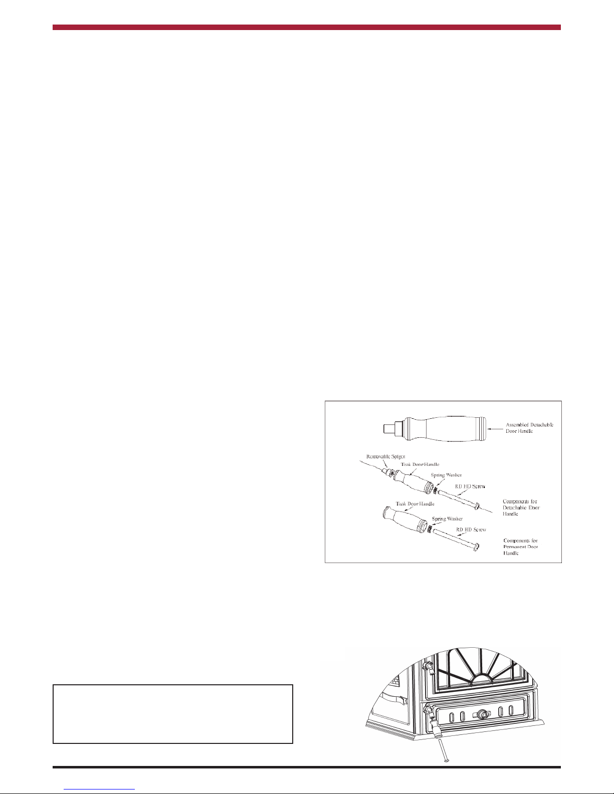
• Fire Door Handle (Assembled) See fig. 1
• Ashdoor Handle (Assembled) See fig. 1
• Damper Assembly
Fig.1
Fig.2
Page 7

(C). Remove the hob and place to one side, tak
ing care not to damage the enamel finish.
(D). Lay the stove on its back taking care not to
damage rear of stove.
(E). Fit the ashtray to the base using the two
1
/4”
x
1
/2” long round head screws and two of the
3
/8” washers provided. Fit the tool holder to
the base using the two
1
/4” x 1 1/2” long coun
tersunk screws, and two of the 3/8” washers
provided (See Fig.4).
Fig.3
(B). Open the fire door using the detachable han
dle and remove the contents from the fire
box.
Fig.4
(F). Fit the secondary air control rod bracket to
the ashtray using the two
1
/4” x 1/2” long
round head screws and the two lock washers
provided. Fit the connecting rod through the
control rod bracket with the notches facing
downwards and leave it hanging loose until
the stove is standing upright. (See Fig.5).
Fig.5
(G). Remove the four M10 bolts from the base,
and fit the four legs using the four M10 x
20mm long bolts and the 3/8” washers pro
vided in the jiffy bag. (See Fig.6).
Fig.6
(H). Stand the stove upright, taking care not to
strain the back leg bolts. Attach the sec
ondary air damper assembly to the back
panel using the two
1
/4” x 3/4” long round
head screws and the two lock washers pro
vided (See Fig.7). Connect the connecting
rod to the secondary air damper assembly
and fix it into place using the split pin and
1
/4” washer provided in the jiffy bag. Ensure
that the ends of the split pin are bent back
with the
1
/4” washer between the casting and
the ends of the split pin.
Fig.7
Secondary Air
Damper Assembly
7
Page 8

FLUES
Flues should be vertical wherever possible and
where a bend is necessary, it should not make an
angle of more than 45owith the vertical. Horizontal
flue runs should be avoided except in the case of a
back outlet from the appliance, when the length of
the horizontal section should not exceed 150mm.
CHIMNEY
Do not connect to a chimney serving another
appliance.
The stove is a radiant room heater and must be connected to a chimney of the proper size and type.
The chimney must have a cross-sectional area of at
least 30 square inches 19350sq. mm or a diameter
of at least 6” (150mm). It is best to connect to a
chimney of the same size, as connection to a larger
size may result in a somewhat less draught.
A flue that has proved to be unsatisfactory, particularly with regard to down draught should not be used
for venting this appliance until it has been examined
and any faults corrected. An existing masonry chimney should be inspected and if necessary repaired
by a competent mason or relined using an approved
lining system.
The stove must be connected to a chimney with a
minimum continuous draught of 0.06 w.g. Poor
draught conditions will result in poor performance.
All register plates, restricter plates, damper etc.,
which could obstruct the flue at a future date should
be removed before connecting this appliance.
If connecting to an existing chimney with a flue
diameter of more that 8” it is recommend to line the
flue using a suitable stainless steel flue liner.
Where a masonry chimney is not available a proprietary type of 6”/150mm - twin wall, fully insulated
pipe may be used. The pipe must terminate at a
point not lower than the main ridge of adjacent outside obstructions. With such installation, access to
the chimney must be provided for cleaning purposes.
A chimney / flue termination must be located to minimise wind effects, a basic guide is that the distance
from the termination to the roof should be at be at
least 2300mm when measured horizontally and at
least 1000mm when measured vertically, (see
Fig.8). In circumstances where there are adjoining
buildings/ structures/ roof openings there are additional requirements, please refer to building regulations part J.
8
2300
1000
Fig.8
Appliance
Soot Door
FLUE EXIT (TOP & REAR)
The stove is designed to allow the chimney be
cleaned through the stove. If the chimney cannot be
cleaned through the stove it is necessary to provide
a soot box/access door in the flue for cleaning. See
Fig.9 for recommended locations. Fit it to the stove
as shown in Fig.9.
Fig.9
Flue Liner
Flue
Soot Door
Debris Collection
space
Sleeve
Flue Pipe
Possible
Positions
for access
Appliance Flue
Outlet
Appliance
Page 9

9
Fig.10
TOP FLUE EXIT
Take the flue spigot and before fitting it to the stove
place a small amount of fire cement on the inside
flange of the outlet and push the flue spigot into
place making sure the spigot is properly sealed to
the stove. Remove any excess cement from the
inside of the flue spigot to prevent obstruction of the
flue way.
REAR FLUE EXIT
Fit the top cover plate to the stove with the two
screws holding on the rear exit cover plate making
sure that the sealing rope is properly seated on the
stove flue outlet. Tighten screws. See Fig.21.
Fig.11
DOWN DRAUGHTS
However well designed constructed and positioned,
the satisfactory performance of the flue can be
adversely affected by down draught caused by nearby hills, adjacent tall buildings or trees. These can
deflect wind to blow directly down the flue or create
a zone of low pressure over the terminal.
A suitable terminal or cowl will usually effectively
combat direct down blow but no cowl is likely to prevent down draught due to a low pressure zone.
(See Fig.12)
Fig.12
Direction of wind
Pressure zone
Direction of wind
Suction zone
Pressure zone
Direction of wind
Suction zone
Pressure zone
Suction zone
Page 10

10
VENTILATION & COMBUSTION AIR REQUIREMENTS
It is imperative that there is sufficient air supply to
the stove in order to support correct combustion.
The air supply to this appliance must comply with
current Building Regulations Part J, Heat Providing
Appliances. If another appliance is fitted in an adjacent room it will be necessary to calculate an additional air supply.
The minimum effective air requirement for this appliance is 53cm². When calculating combustion air
requirements for this appliance use the following
equation:
550mm² per each kw of rated output above 5kw
should be provided, where a flue draught stabiliser is
used the total free area shall be increased by
300mm² for each kw of rated output.
NOTE:
There must not be an extractor fan fitted in the same
room as the stove as this can cause the stove to
emit smoke and fumes into the room.
All materials used in the manufacture of air vents
should be such that the vent is dimensionally stable,
corrosion resistant, and no provision for closure.
The effective free area of any vent should be ascertained before installation. The effect of any grills
should be allowed for when determining the effective
free area of any vent.
Air vents should be positioned so that they are not
liable to blockage.
Air vents direct to the outside of the building should
be located so that any air current produced will not
pass through normally occupied areas of the room.
An air vent outside the building should not be located less than the dimensions specified within the
Building Regulations and B.S. 8303: Part 1 from any
part of any flue terminal. These air vents must also
be satisfactorily fire proofed as per Building
Regulations and B.S. 8303: Part 1.
Air vents in internal walls should not communicate
with bedrooms, bedsits, toilets, bathrooms or rooms
containing a shower. Air vents traversing cavity walls
should include a continuous duct across the cavity.
The duct should be installed in such a manner as not
to impair the weather resistance of the cavity.
Joints between air vents and outside walls should be
sealed to prevent the ingress of moisture. Existing
air vents should be of the correct size and unobstructed for the appliance in use.
If there is an extraction fan fitted in adjacent rooms
where this appliance is fitted, additional air vents
may be required to alleviate the possibility of
spillage of products of combustion from the appliance/flue while the fan is in operation. Refer to B.S.
8303 Part 1.
Where such an installation exists, a test for spillage
should be made with the fan or fans and other appliances using air in operation at full rate, (i.e.extraction
fans, tumble dryers) with all external doors and windows closed.
If spillage occurs following the above operation, an
additional air vent of sufficient size to prevent this
occurrence should be installed.
Especially Airtight Properties:-
If the stove is being fitted in a property where the
design air permeability is less than 5m
3
/ (h.m2) (normally newer properties built from 2006), then a permanent ventilation must be fitted to provide 550mm
2
of ventilation for each kW of rated output. If a
draught stabiliser is also fitted then the requirement
is 850mm
2
per kW of rated output.
LOCATION
There are several conditions to be considered in
selecting a location for your Stanley Erin Stove.
a. Position in the area to be heated, central
locations are usually best.
b. Allowances for proper clearances to
combustibles.
c. Allowances for proper clearances for
maintenance work.
CLEARANCE TO COMBUSTIBLES
Maintain at least the following clearances to all
combustible material:
From the front (36”) 910 mm
From the back (35”) 900 mm
From the sides (28”) 700 mm
From the flue pipe (36”) 910 mm
straight up only
It is recommended that this appliance is sited next to
and on a non-combustible surface. A minimum all
round clearance of 150 mm will allow air circulation
and not impede the performance of the stove.
Page 11

11
Fig.13
127mm
127mm
127mm
460mm
FLOOR PROTECTION
When installing this heater on a combustible floor, a
floor protector, consisting of a layer of non combustible material at least
3
/8” (10mm) thick or 1/4”
(6mm) thick covered with
1
/8” (3mm) sheet metal. It
is required to cover the area under the heater and to
extend to at least 18” (460mm) at the front and 8”
(200mm) to the sides, and rear, this will provide protection from sparks and embers which may fall out
from the door when stoking or fuelling, See Fig. 13
STOVE DIMENSIONS
Fig.14
Fig.15
WARNING: DO NOT OBSTRUCT PRIMARY
AIR SUPPLY TO THE STOVE
Note: Dimensions stated are in millimetres and
may be subject to a slight +/- variation.
COMMISSIONING AND HANDOVER
On completion of the installation allow a suitable
period of time for any fire cement and mortar to dry
out, when a small fire may be lit and checked to
ensure the smoke and fumes are taken from the
stove up the chimney and emitted safely to the
atmosphere. Do not run at full output for at least
24 hours.
Ensure that the operating instructions for the stove
are left with the customer. Ensure to advise the customer on the correct use of the appliance with the
fuels likely to be used on the stove and warn them to
use only the recommended fuels for the stove.
Advise the user what to do should smoke or fumes
be emitted from the stove. The customer should be
warned to use a fireguard to BS 8432:2010 in the
presence of children, aged and/or infirm persons.
OPERATION
Check that all dampers and catches are operating
correctly and ensure that all flue connections are
thoroughly sealed.
Page 12

12
Fig.16
The stove has three independent air controls:
1. The primary air control knob on the ashdoor
(See fig. 16 &17). Move the knob to the right
to open and to the left to close.
2. The air wash control which is located above
the firedoor (See fig. 16), turn anti-clockwise
to open and clockwise to close (See fig. 18).
The air wash control is hot when the appli
ance is in use, the ashpan handle is a com
bined operating tool and can be used to
operate this knob or use the glove provided.
3. The secondary air is adjusted by adjusting
the position of the secondary air connecting
rod which is located underneath the ashtray
(See fig. 16 & fig. 19). Pull the rod out to
open and push it in to close.
AIR CONTROLS
Fig.17
Primary Air Control
Full Open
Other Settings
Fully Closed
Air Wash Control
Fig.18
Fig.19
NOTE: When burning anthracite or smokeless coal,
the air wash and secondary air damper must be
closed.
RECOMMENDED FUELS
All fuels should be stored under cover and kept
as dry as possible prior to use.
This appliance has been tested using seasoned
wood logs and manufactured briquetted smokeless
fuel (Ancit) for closed appliances, sized between
20g and 140g. Other fuels are commercially available and may give similar results. Wood logs up to
340mm long are suitable. All fuels should be stored
under cover and kept as dry as possible prior to use.
Do not use fuels with a Petro-coke ingredient as this
may cause the grate to overheat, causing damage.
Reduced outputs will result when fuels of lower
calorific values are used. Never use gasoline or
gasoline type lantern fuel, kerosene, charcoal lighter
fluid or similar liquids to start or freshen up a fire in
this heater. Keep all such liquid well away from the
heater at all times. Operate the stove only with the
fuelling door closed except for re-fuelling.
This stove has obtained HETAS Ltd approval for
burning natural and manufactured smokeless fuels
only as detailed in recommended fuels below.
HETAS Approval does not cover the use of other
fuels either alone or mixed with the recommended
fuels listed, nor does it cover instructions for the use
of other fuels.
Page 13

13
OUTPUT TO ROOM TOTAL OUTPUT
NOMINAL MAX. NOMINAL MAX.
WOOD LOGS 10.2 kW 10.2kW
MANUFACTURED
SMOKELESS FUEL
10.4 kW 14.7kW 10.4kW 14.7kW
TECHNICAL DATA
Typical refuelling intervals to obtain nominal
outputs
Wood 1.5 hours 5.5kgs
MSF 4 hours 6.5kgs
Flue Gas Mass Flow Wood 7.7 g/s
MSF 8.2 g/s
Flue Gas temp at nominal output 344oC
Gross Weight: 172 kgs
Flue Outlet 153 mm Log size 406 mm
This appliance has been tested in
accordance with BS EN 13240
Flue draught 15 Pascals
Model
Energy
Efficiency
Class
Heat Output
to Room
Heat Output
to Water
Energy
Efficiency
Index
Preferred
Fuel
Nominal
Heat
Output
Net Efficiency
Erin NB SF
Stove
A 10.2 N/A 98.45 Wood 10.2 74.1
LIGHTING
Before lighting the stove check with the installer that the installation work and commissioning checks described
previously have been carried out correctly and that the chimney has been swept clean, is sound and free from
any obstructions. As part of the stoves commissioning and handover the installer should demonstrate how to
operate the stove correctly.
USER INSTRUCTIONS
LIGHTING THE STOVE
1. Open firedoor and open the primary air inlet by sliding the control knob on the ashpit door to the right
hand side.
2. Open the secondary air inlet by pulling it out and open the air wash control by turning it anti-clockwise.
3. Cover the grate with crumpled pieces of paper and lay 10-12 pieces of kindling on top of the paper
towards the back of the firebox.
4. lgnite and close the fire door.
5. When the kindling is well alight open the fire door and add more kindling of a larger size to sustain the
fire. Close the fire door.
6. When a hot fire bed is established add the normal fuel.
7. When well lighted, adjust the air controls as required depending on the fuel type being used & the heat
output required. The controls should be adjusted in conjunction with each other to get the appropriate
burn rate with exact settings on each control depending on the draught conditions of the chimney to
which the unit is connected.
Page 14

14
FULLY
OPEN
FULLY
OPEN
FULLY
OPEN
0-10%
OPEN
0-80%
OPEN
0-80%
OPEN
FULLY
OPEN
FULLY
OPEN
FULLY
OPEN
0-80%
OPEN
0-50%
OPEN
0-50%
OPEN
FULLY
OPEN
FULLY
CLOSED
FULLY
CLOSED
0-80%
OPEN
FULLY
CLOSED
FULLY
CLOSED
PRIMARY AIRWASH SECONDARY PRIMARY AIR WASH SECONDARY
IGNITION CONTROLLED BURN
AIR CONTROLS
FUEL
ANTHRACITE
COAL
WOOD/ TURF
Riddle the fire using the operating tool (see Fig.
20). Before opening the door, move the primary air
control knob fully to the right (i.e. fully open) as this
will help to eliminate any smoke or fly ash resident
in the combustion chamber. Add fuel to the fire,
close the door and reset the primary air control
knob to the desired setting.
RE-FUELLING
Fig.20
SLOW BURNING
Slow burning will cause the window glass to blacken and should not be used for a long period. It
should only be done after the fire has been established and been running at nominal output for a
period of time. For a prolonged show burn, fill the
firebox with fuel up to the maximum height just
below the top of the fire fence at the front of the
door opening.Close all controls fully.
DE-ASHING
When ash build-up becomes excessive in the fire
chamber shake the firebars by inserting the operating tool into the square slot on the right side of the
stove. (See Fig. 20)
DISPOSAL OF ASHES
Your stove is provided with a steel ashpan. This ashpan should be emptied every day.
If ashes are allowed to build to grate level you could
damage the firebars by overheating. We recommend that you remove ashes after you have riddled
the fire following overnight burn.
Ashes should be placed in a metal or other noncombustible container with a tight fitting lid. The
closed container of ashes should be placed on a
non-combustible material, pending final disposal. If
ashes are buried in soil, or otherwise dumped they
should be retained in the closed container until they
are thoroughly cooled. Open the ashdoor and
remove the ashpan using the tool provided, see Fig.
21. Close the ashdoor. When the ash is disposed of
replace the ashpan.
REMEMBER COAL GASES ARE TOXIC
Fig.21
Replace ashpan. Close ashpit door
Ashpan
Page 15

15
MONTHLY MAINTENANCE
Cleaning Stove Flue Pathways
It is recommended that the flue pathways in the
stove are cleaned on a monthly basis (or less
depending on the soot build-up created by the fuel
being used) and the chimney cleaned annually. To
access the chimney pathways, use the following
procedure (See fig. 22)
1. Remove the hob and place to one side, tak
ing care not to damage the enamel finish.
2. Remove the heat exchanger by unscrewing
the four 1/4” round head screws, and insert
the cleaning brush.
3. Replace the heat exchanger, ensuring that
the rope has not moved out of position or
been damaged.
4. Replace the hob before relighting the fire.
PERIODIC MAINTENANCE
Fig.23
Hob
Screws
Cleaning Firebox
Chamber
Fig.22
ADJUSTING THE DOOR CATCH
Over time, the fire door latch can loosen due to the
continual compression and hardening of the rope
seal between the door and the front casting. The
position of the latch can be easily adjusted (in
order to tighten the door closure) by removing the
nut holding on the door latch and repositioning the
washers between the latch & the door casting to
allow the latch to be positioned closer to the back
of the door casting - see Fig. 23 & 24.The tightness
of the door seal should be checked after each
adjustment is made. lt is recommended that the
rope seals on the stove are changed at least every
two years or sooner if the seal loses its integrity.
Fig.24
Page 16

16
CHIMNEY CLEANING
The chimney should be cleaned twice annually or if
the stove is not used for a prolonged period during
the summer period, it should be cleaned prior to
commencement of usage. The flue liner should be
cleaned in accordance with manufacturer's instructions. Always use a brush with plastic bristles that is
the correct size to reach all areas of the flue.
GLASS CLEANING
The stove glass will self-clean when there is sufficient heat generated by the burning fuel i.e. when
the unit is operated at the maximum air settings. If a
build-up of creosote occurs on the glass it may be
due to low draft conditions, poor quality fuel or operating the stove at the minimum air settings for long
periods of time. The glass should be cleaned when
cool and cleaned with a non-abrasive cloth using
warm soapy water. For stubborn deposits, a grade 0
steel wool can be used whilst tak¡ng care not to
scratch the glass with any coal/ash deposits.
VITREOUS ENAMEL CLEANING
General cleaning must be carried out when the
stove is cool.
If this stove is finished in a high gloss vitreous
enamel, to keep the enamel in the best condition
observe the following tips:
1. Wipe over daily with a soapy damp cloth,
followed by a polish with a clean dry duster.
2. For stubborn deposits a soap impregnated
pad can be carefully used on the vitreous
enamel.
3. Use only products recommended by the
Vitreous Enamel Association, these products
carry the Vitramel label.
A detailed list of the approved cleaners can be found
on their website www.vea.org.uk/enamel-care/
CLEANING A MATT BLACK/SENOTHERM
STOVE
Cleaning should be done when the stove is cold by
removing any dust or dirt using a dry cloth. Do not
use any water on the matt black/senotherm finish as
this will cause it to rust.
DO NOT USE ABRASIVE PADS OR OVENCLEANSERS CONTAINING CITRIC ACID ON
ENAMELLED SURFACES. ENSURE THAT THE
CLEANSER MANUFACTURERS INSTRUCTIONS
ARE ADHERED TO.
NOTE: Small impact marks on the enamel finish can
be repaired using an appropriate enamel
touch up (a touch up bottle
is included with
the stove packaging) but it should not be
used to cover marks greater than ø10mm or
multiple marks on the same casting/area.
PROLONGED PERIODS OF NON USE
If the stove is to be left unused for a prolonged period of time then it should be given a thorough clean
to remove ash and unburned fuel residues. To
enable a good flow of air through the appliance to
reduce condensation and subsequent damage,
leave the air controls fully open.
It is important that the flue connection, any appliance
baffles or throat plates and the chimney are swept
prior to lighting up after a prolonged shutdown
period.
WARNING NOTE:
Properly installed, operated and maintained this
stove will not emit fumes into the dwelling.
Occasional fumes from the de-ashing and refuelling may occur. However, persistent fume emission is potentially dangerous and must not be tolerated. If fume emission does persist, then the following immediate action should be taken:
(a) Open doors and windows to ventilate room.
(b) Let the fire out or eject and safely dispose of
fuel from the stove.
(c) Check for flue or chimney blockage and clean if
required.
(d) Do not attempt to relight the fire until the cause
of the fume emission has been identified and
corrected. If necessary seek expert advice.
The most common cause of fume emission is flueway or chimney blockage. For you own safety
these must be kept clean at all times.
Page 17

GLASS REPLACEMENT
(a) Open the firedoor fully.
(b) Remove the four corner screws and clips and
carefully remove the broken glass.
(c) Clean the glass recess in the door.
(d) Replace the sealing rope in the door if
necessary
(e) Tighten screws.
(f) Replace glass only with ceramic glass 5mm
thick. (See Fig. 25).
Fig.25
TO REPLACE DAMAGED BRICKS
Clean the firebox thoroughly and remove any fire
cement in the joints of the bricks. Remove the left
and right hand front bricks. Remove the two back
bricks. To remove the side bricks (left or right), lift
the top side brick up and hold it in position. Lift up
the bottom side brick to clear the rocker bar frame
then swing the bottom brick and take it out. Lower
the top firebrick and take it out at the firebox.
Replace the damaged brick and replace the bricks
by doing the reverse of the above.
17
FIRE SAFETY
To provide reasonable fire safety, the following
should be given serious consideration.
1. Do not over fire the stove.
2. Over-firing will also damage painted or enamel
finish.
3. Install a smoke detector in the room.
4. A conveniently located class A fire extinguisher to
contend with small fires resulting from burning
embers.
5. A practical evacuation plan.
6. A plan to deal with a chimney fire as follows:-
(a) Notify the fire department.
(b) Prepare occupants for immediate evacua-
tion.
(c) Close all openings into the stove.
Fig.26
CO ALARM
The fitting of CO Alarms in the same room as the
appliance is a compulsory requirement under current Building Regulations. For ROI an additional CO
Alarm must be fitted either inside each bedroom or
within 5 metres of the bedroom door, refer to
Building Regulations Part J. Further guidance on the
installation of a carbon monoxide alarm is available
in BS EN 50292:2002 and from the alarm manufacturers instructions.
Provision of an alarm must not be considered a
substitute for either installing the appliance
correctly or ensuring regular servicing and
maintenance of the appliance and chimney
system.
WARNING:-
If the CO Alarm sounds unexpectedly:-
1. Open Doors and windows to ventilate the
room and then leave the premises.
2. Let the fire go out.
Page 18

18
ERIN SOLID FUEL STOVE EXPLODED VIEW
1. TOP FLUE OUTLET - B00053AXX
2. LEG (SHORT) - B00054AXX
3. TOP FLUE BLANKING PLATE - B00055AXX
4. ASHTRAY - B00056AXX
5. HOB - B00057BXX
6. DOOR GRILL - B00058AXX
7. FIRE DOOR - B00059CXX
8. ASHPIT DOOR - B0061CXX
9. AIR CONTROL KNOB - B00063AXX
10. LEFT HAND SIDE PANEL - B00066EXX
11. PRIMARY AIR SLIDE - B00067AXX
12. FRONT FRAME - B00069EXX
13. RH SIDE CASTING - B00071BXX
14. RIDDLING TOOL - B00076AXX
15. TOOL HOLDER - B00078AXX
16. BASE - B00079CXX
17. BACK PANEL - B00080AXX
18. PRIMARY AIR CONTROL KNOB - B00153AXX
19. SECONDARY AIR DAMPER BKT - B00389AXX
20. SECONDARY AIR DAMPER - B00391AXX
21. INNER TOP - B00553AXX
22. ACESS PLATE - B00578AXX
23. DOOR GLASS CLIP - F00003AXX
24. ASHPAN - F00018AXX
25. PRIMARY AIR SLIDE CLIP - F00019AXX
26. GASKET CLAMP PLATE - F00022AXX
27. TOP LATCH COVER PLATE - F00023AXX
28. LOWER LATCH COVER PLATE - F00024AXX
29. SIDE SUPPORT CLIP - F00029AXX
30. PLATE TO DAMPER - F00833AXX
31. FIRE BRICK SIDE - H00012AXX
32. BACK BRICK - H00013AXX
33. LH FRONT BRICK - H00014AXX
34. RH FRONT BRICK - H00015AXX
35. FIRE BRICK BOTTOM LEFT - H00016AXX
36. BOTTOM SIDE BRICK - RH - H00017AXX
37. SERIAL NUMBER PLATE - N00234BXX
38. DATA PLAQUE - N00476AXX
39. PRIMARY AIR BOX - Q00028AXX
40. PRIMARY AIR SHUTTER - Q00029AXX
41. FRONT ROCKER BAR CLAMP - Q00030AXX
42. SHAKER BARREL - Q00037AXX
43. FRONT ROCKER BAR - Q00044AXX
44. BACK ROCKER BAR - Q00045AXX
45. ROCKER BAR FRAME - Q00047BXX
46. FIRE FENCE RETAINER - Q00048CXX
47. AIR DUCT BACK PLATE - Q00049AXX
48. AIR INLET BOX - Q00571AXX
49. BACK FLUE COVER PLATE - Q00578AXX
50. BAFFLE - Q00753AXX
51. GLASS - T00003AXX
52. DOOR HANDLE (SHORT) - U00008AXX
53. DOOR HANDLE LONG - U00009AXX
54. HINGE - U00153AXX
55. SECONDARY AIR CON ROD BKT - V00017BXX
56. OPERATION TOOL - V00020BXX
57. SPIGOT TO DOOR HANDLE - V00021AXX
58. DOOR HANDLE AXLE - V00022BXX
59. DOOR LATCH - V00023AXX
60. CONICAL SPRING - V00024AXX
61. PRIMARY AIR CONTROL SHAFT - V00027AXX
62. SPACER - V00033AXX
63. SPRING - V00034AXX
64. SPACER - V00039AXX
65. AIR SLIDE SPINDLE - V00067AXX
66. CON ROD TO AIR DAMPER - V00068AXX
67. SPACER - V00489AXX
68. BADGE - V00730BXX
69. TOP AIR DUCT PLATE - Z00001AXX
70. BOTTOM AIR DUCT PLATE - Z00002AXX
71. FIRE FENCE - Z00003AXX
72. SECONDARY AIR BACK PLATE - Z00006AXX
Page 19

19
NOTES
Page 20

Manufactured by
Waterford Stanley Ltd.,
Unit 401-403, IDA Industrial Estate, Cork Road,
Waterford, Ireland.
Tel: (051) 302300 Fax (051) 302315
Item No: N00229AXX
YS 150517Rev 018
20
 Loading...