

Stanley Dura-Glide 2000, Dura-Glide 5300, Dura-Glide 3000, Dura-Glide 5200, ProCare 8300A Installation And Operation Manual
Page 1

iQ Controller
Installation and Operation Manual
204144
INCLUDES INSTRUCTIONS FOR
DURA-GLIDE™ 2000/3000, 5200/5300,
DURA-GUARD™, DURA-STORM™, DURACARE™, *5400-SERIES,
*PROCARE™ 8300A, AND DURACARE 7500A TL-FBO
AUTOMATIC SLIDE DOOR SYSTEMS
*Refer to product-specic Installaon Manuals for Wiring Diagrams as they contain the relevant system wiring.
Stanley Part Number 204144
REV B 01.2019
All manuals can be found at
www.stanleymobileapps.com
Copyright 2019, Stanley Access Technologies, LLC.
Prohibition on Copying: Any unauthorized reproduction, disclosure or distribution of copies by
any person of any portion of this work may be a violation of copyright law of the United States
of America and other countries, could result in the awarding of statutory damages of up to
$250,000 (17 USC 504) for infringement, and may result in further civil and criminal penalties.
All rights reserved.
Page 2

Table of Contents
General Description ........................................................................................................... 2
Intended Use ............................................................................................................................................. 2
Applicability ............................................................................................................................................... 3
Prerequisites .............................................................................................................................................. 3
Precautions ................................................................................................................................................3
Installation Instructions .................................................................................................... 3
Installing the iQ Controller ................................................................................................................. 3
Wiring Instructions ............................................................................................................ 3
Evaluating Power Requirements ........................................................................................................ 3
Connecting Main Power Wiring ........................................................................................................4
Connecting Accessories (As Applicable) ......................................................................................... 4
Tune-In Instructions ........................................................................................................... 4
Handing for FIS Only .............................................................................................................................. 5
Tuning In the iQ Controller Using the Controller Pushbuttons ........................................... 6
Tables ............................................................................................................................................................ 7
Final Tune-In Adjustments .................................................................................................................18
Attachments ..................................................................................................................... 19
Attachment 1 - iQ Controls and Indicators .................................................................................19
Attachment 2 - iQ System Wiring Diagram ...............................................................................21
Attachment 3 - iQ Terminal Block Connections TB1-TB7 ..................................................... 31
Attachment 4 - ANSI/BHMA and UL Compliance Requirements for Sliding Doors ..32
Attachment 5 - Troubleshooting Aid ............................................................................................ 35
Attachment 6 - iQ Troubleshooting Aid ...................................................................................... 36
Attachment 7 - Fine Tuning Slide Doors .....................................................................................37
1
GENERAL DESCRIPTION
Intended Use
This manual provides installaon instrucons, wiring instrucons, and tune-in instrucons for the iQ
Controller. It includes instrucons for Dura-Glide™ 2000/3000, 5200/5300, Dura-Guard™, Dura-Storm™,
All rights reserved. Reproduction
Dura-Max™ 5400-Series*, ProCare™ 8300A*, and DuraCare™ 7500A TL-FBO Automac Slide door systems.
On Dura-Glide sliding doors, the iQ Controller replaces the MC521 and MC521Pro, or both the
microprocessor control box and the interface board on older models. The door acvaon devices (SU-100
moon sensors, carpets, control mats, push plates, etc.), lock, funcon switch, doorway holding beams, and
door posion switches previously connected to the interface board must be connected to the iQ Controller.
Aachment 1 illustrates the iQ Controller controls and indicators. Aachment 2 illustrates system wiring for
Dura-Glide series sliders.
This manual supports the hardware and rmware at the me of this released revision.
Applicability
Copyright 2019 Stanley Access Technologies, LLC.
in whole or in part without the express written permission of Stanley is prohibited.
This manual is applicable to the Dura-Glide series sliding doors used on Dura-Glide™ 2000/3000, 5200/5300,
Dura-Guard™, Dura-Storm™, Dura-Max™ 5400-Series, ProCare™ 8300A, and DuraCare™ 7500A TL-FBO
Automac Slide door systems.
Instrucons for connecng oponal accessories are not provided in this manual.
01.25.2019
2 Document # 204144 REV B • www.stanleyaccess • 1.800.7.ACCESS
Page 3

iQ Control Box
Prerequisites
Special Items Required:
• Stanley Access Technologies document No. 203957, “SU-100 Moon Sensor Installaon and Operaon” (if
installed).
• SU-100 tune-in remote control (if SU-100 Moon Sensor is installed).
• Stanley Access Technologies document No. 203768, “StanguardTM Threshold Sensor Installaon and Operaon”
(if installed).
• Optex X Zone T or X Zone ST manufacturer’s installaon and tune-in instrucons (if installed).
• Hotron HR100 ST manufacturer’s installaon and tune-in instrucons (if installed).
• Bluetooth adapter or cable to connect compable handheld device to iQ Controller.
• Degreaser.
• Instrucons for any other device to be wired into the iQ Controller.
Precautions
All ANSI/BHMA and UL Requirements in Attachment 4 must be met before the door is put into operation.
2
INSTALLATION INSTRUCTIONS
Installing the iQ Controller
NOTE: This manual covers new door installaons in which the iQ is factory-installed and wired.
3
WIRING INSTRUCTIONS
Evaluating Power Requirements
• ENSURE power source is a dedicated 115 VAC, 50/60 Hz source with 20A circuit rang. If four operators are
used, the source should have a 30A rang.
• ENSURE no more than four operators will be connected to one circuit.
• ENSURE power source is not shared with other equipment, i.e., cash registers, EAS systems, or other
electromagnec interference generators.
Copyright 2019, Stanley Access Technologies, LLC. All rights reserved. Reproduction
1.800.7.ACCESS • www.stanleyaccess.com • Document # 204144 REV B 3
in whole or in part without the express written permission of Stanley is prohibited.
01.25.2019
Page 4

iQ Control Box
Connecting Main Power Wiring
Warning: To prevent injury to personnel, incoming electrical power to the header must be de-energized
before connecng electrical service to the control box.
Warning: All electrical wiring must conform to Naonal Electrical Code Requirements.
1. DE-ENERGIZE incoming electrical power to header.
2. Refer to Aachment 2, and, using wire nuts, CONNECT incoming line, neutral, and ground wires
to the controller power harness.
3. IF adhesive wire clamps will be used, DE-GREASE metal surfaces on inside of header cover
where clamps will mount.
4. SECURE wiring to top of the header track tube, and ENSURE the following:
• All wires are clear of belts and belt brackets.
• Header cover opens and closes without interference.
Connecting Accessories (As Applicable)
Refer to Aachments 2 and 3, and CONNECT any of the following subsystems to the iQ Controller:
• Funcon switch (rotary, rocker and “POWER” switch wiring).
• StanguardTM threshold sensor.
• Doorway holding beam(s).
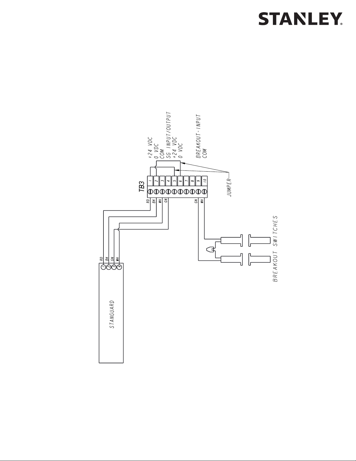
• Breakout switch.
• Solenoid lock.
• SU-100 moon sensor(s) wiring (refer to Stanley Document #203957).
• Optex X Zone T and X Zone ST Sensor(s) wiring.
• Push plate wiring.
• Door posion switch closed contact (with door closed).
• Hotron HR100 ST Sensor(s) wiring.
All rights reserved. Reproduction
4
TUNE-IN INSTRUCTIONS
Warning: The door path must be free of objects and remain clear unl the First Install Sequence (FIS)
is complete. During this sequence the sensors are inacve and the door has no SAFETY. To stop the door,
turn power off or put the doors into breakout.
NOTES:
1. Tune-In: The iQ Controller can be tuned-in using a handheld device or using the pushbuon switches
located on the controller. Tune-in using a handheld device is the preferred method.
Copyright 2019, Stanley Access Technologies, LLC.
in whole or in part without the express written permission of Stanley is prohibited.
01.25.2019
4 Document # 204144 REV B • www.stanleyaccess.com • 1.800.7.ACCESS
2. Status Codes: During normal operaon, the digital display indicates status codes. The “UP” and “DOWN”
pushbuon switches can be used to enter and display data values. The user interface values are shown
in Tables 2 through 4.
Page 5

iQ Control Box
PULLEY ROTATES CCW
WHILE OPENING
USE RIGHT HAND IN FIS
PULLEY ROTATES CW
WHILE OPENING
USE LEFT HAND IN FIS
RIGHT HAND
LEFT HAND
HANDING
3. Solenoid Lock: If a solenoid lock is installed with no lock circuit board (new style), set Lock Logic to the
actual lock type (Fail Safe or Fail Secure). If a Fail Safe or Fail Secure Lock is being installed with a lock circuit
board (old style), the Lock Logic must be set to Fail Secure.
4. Handing (For purpose of FIS only): Manually open door nong rotaon of belt pulleys. If counter clockwise (CCW)
use right hand during FIS. If clockwise (CW) use le hand during FIS. See gure below.
5. FIS: The rst installaon sequence (FIS) is used to perform the inial conguraon. Upon compleon of FIS, all
setup parameters are stored in non-volale memory. Subsequent power cycles will reload the
conguraon parameters that were congured during FIS.
6. Decimal points on digital display are encoder 1 signals. Rotang motor will cause decimal points to blink
and appear to dim.
7. Aer changing values, the values must be saved in non-volale memory by cycling the door to full open.
Copyright 2019, Stanley Access Technologies, LLC. All rights reserved. Reproduction
in whole or in part without the express written permission of Stanley is prohibited.
1.800.7.ACCESS • www.stanleyaccess.com • Document # 204144 REV B 5
01.25.2019
Page 6

iQ Control Box
Tuning In the iQ Controller Using the Controller Pushbuttons
1. To change the INDEX and VALUE:
To show the INDEX press and hold ENTER, the current INDEX will display. Once ENTER is released, the display
will show the VALUE of that INDEX. Aer 2.5 seconds, the display will return to the current status code.
2. To change the INDEX:
Hold ENTER switch while pressing UP or DOWN to get desired INDEX.
3. To change a VALUE:
a. Unlock the keypad by seng index 99 to value 00.
b. Aer the desired INDEX is selected, release ENTER and within 2.5 seconds press UP or DOWN to get the
desired VALUE. (If the UP or DOWN buons are not pressed within 2.5 seconds of releasing the ENTER
buon, the display will change from the VALUE back to the STATUS.)
4. To display STATUS CODE:
A few seconds aer the VALUE is selected, the display indicates the STATUS CODE.
5. Refer to Tables 2 and 3 for a list of index seng descripons and values. Read the descripons enrely
before performing each step. Check the INDEX and VALUE aer each step.
6. To STORE CHANGES in permanent memory:
Cycling door open one me will store changes.
7. To LOCK keypad:
Lock keypad by seng index 99 to value 01 or by turning power OFF and then ON.
8. To ACCESS the door cycle counter funcon:
a. Ensure that the keypad is locked by seng index 99 to 01.
b. Ensure that the index is set to any index but 99.
c. Press the up or down key to access the door cycle counter.
The display will show “dc” followed by four pairs of digits, followed by “dc”.
Example: If the Door Count was 12345678 cycles the controller will display “dc” “12” “34” “56” “78” “dc”.
All rights reserved. Reproduction
Copyright 2019, Stanley Access Technologies, LLC.
in whole or in part without the express written permission of Stanley is prohibited.
01.25.2019
6 Document # 204144 REV B • www.stanleyaccess.com • 1.800.7.ACCESS
Page 7

iQ Control Box
Table 1. FIS Procedure using Pushbuttons
Step Description Display
Index Value Status Code
1 Set Funcon Switch to Closed.
2 Turn power on.
3 Unlock keypad. 99 00 00
4 Restart FIS. 96 01 A0
5 Select door type: Slide, 01 single motor or 02 dual motor. 00 01 (Single)
02 (Dual)
6 Select Handing: 00 Right or 01 Le.
Manually open door and note rotation of belt pulleys.
If counterclockwise (CCW) use right hand during FIS.
If clockwise (CW) use left hand during FIS.
01
7 Accept FIS. Display will go to A1. 03 01 A1
8 Make changes: Funcon Switch
11 01 (Rocker)
01 Rocker or 00 Rotary. The INDEX will start at 00.
9 Select Lock Logic: Lock Logic, 00 = Fail Safe; 01 = Fail Secure;
07 Lock Logic:
02 = Fail Safe Dura-Max; 03 = Fail Secure Dura-Max.
NOTE: For locks with circuit board, set to 01 Fail Secure.
For locks with no circuit board, set to Fail Safe
or Fail Secure.
10
Warning: During this sequence the sensors are inactive and the door
has NO SAFETY. To stop the door, TURN POWER OFF or PUT THE DOOR
INTO BREAKOUT.
Function Switch: Switch to OPEN, momentarily, then CLOSED/
LOCKED. The door opens fully, delays and then closes fully.
The iQ displays A2 when FIS is completed.
11 Aer FIS is complete it might be necessary to change index
11 (safety logic) and Index 20 (Safety Beam Type) to match
the systems installed.
Adjust any other index sengs as needed (refer to Table 3
for opons).
12 Lock keypad. 99 01 00
13 Final Tune-In.
Walk test doors to conrm compliance with applicable ANSI
Standards and local codes.
00 (Right)
01 (Le)
00 (Rotary)
00 = Fail Safe
01 = Fail Secure
02 = Fail Safe
Dura-Max
03 = Fail Secure
Dura-Max
A0
A1
A2
Copyright 2019, Stanley Access Technologies, LLC. All rights reserved. Reproduction
1.800.7.ACCESS • www.stanleyaccess.com • Document # 204144 REV B 7
in whole or in part without the express written permission of Stanley is prohibited.
01.25.2019
Page 8

iQ Control Box
Table 2. Index List
Index Description
0 - 99 Sengs Values, see Table 3.
90 - 95 Reserved.
96 Command – Restart FIS. Entering “01” will cause FIS to restart.
97 Firmware – Entering “01” will display “FE” followed by two pairs of digits followed by “FE”. For example,
if the rmware was 0609 the controller will display “FE” “06” “09” “FE”.
98 Command – Restart auto conguraon. Entering “01” sets the Control Box to “A1” keeping all previous
values and then re-learns the encoder count.
99* Command – Lock. Entering “01” will lock all value inputs except this index. This prevents inadvertent
changes to input values. Values may be unlocked by entering “00” in this index.
Table 3. Settings
Index Min.
Value
0 1 99* Open
1 1 99* Close
All rights reserved. Reproduction
2 1 99* Open
Copyright 2019, Stanley Access Technologies, LLC.
in whole or in part without the express written permission of Stanley is prohibited.
Max
Value
Speed
Speed
Check
Speed
Open Speed is the speed used during normal operaon
in the opening state (02).
This speed is set to change how long it takes the door
to open.
This parameter sets the target speed seng. Other
parameters like open torque, open startup torque, open
startup length, and open acceleraon as well as door
properes like fricon, door length, and door weight
aect door speed.
Close Speed is the speed used during normal operaon in the
closing state (07).
This speed is set to change how long it takes the door
to close.
This parameter sets the target speed seng. Other
parameters like Close Torque, Close Startup Torque, Close
Startup Length, and Close Acceleraon as well as door
properes like fricon, door length, and door weight aect
door speed.
Open Check Speed is the speed used during normal
operaon in the open check state (04) prior to arriving at
full open.
This speed is set to determine how fast the door arrives at
full open aer open speed.
This parameter sets the target speed seng. Other
parameters like open check torque, open acceleraon,
and open braking as well as door properes like fricon,
door length, and door weight aect door speed.
Defaults
Single Dual
99 99
35 25
10 10
NOTE: With the iQ Toolbox, the Max Values are 125.
Table 3 Settings continued next page.
01.25.2019
8 Document # 204144 REV B • www.stanleyaccess.com • 1.800.7.ACCESS
Page 9

iQ Control Box
Table 3. Settings (continued)
Index Min
Value
Max
Value
Description Defaults
3 5 99 Open Check Length Open Check Length is the percent of door
length in which the door starts to slow down to
open check speed.
This parameter typically is adjusted based on
door weight and open speed seng.
4 5 99 Close Check Length Close Check Length is the percent of door length
in which the door starts to slow down to Close
Check Speed.
This parameter typically is adjusted based on
door weight and Close Speed seng.
5 1 99 Reduced Open
Length
Reduced Open Length is the percent of door length
from the full open posion the door will stop at if in
reduced open mode.
6 1 99 Hold Open Delay Delay that the door stays open aer all sensors
have cleared (0 to 25 seconds).
7 0 3 Lock Logic Select to choose desired Lock Logic.
NOTE: Dura-Max 5400 logic is dierent and has
its own two opons:
00 = Fail Safe (unlocked when power
is removed),
01 = Fail Secure (locked when power
is removed),
02 = Dura-Max Fail Safe (unlocked when power
is removed),
03 = Dura-Max Fail Secure (locked when power
is removed).
8 1 99* Open Torque Open Torque is the torque used during normal
operaon following the end of open startup
length.
Single Dual
40 25
15 15
1 1
15 15
1 1
40 45
This torque must be set to comply with BHMA/
ANSI door force requirements.
This parameter sets the maximum current
available to the motor which is directly
proporonal to the door force. This torque
seng is used in conjuncon with open speed.
Table 3 Settings continued next page.
1.800.7.ACCESS • www.stanleyaccess.com • Document # 204144 REV B 9
Copyright 2019, Stanley Access Technologies, LLC. All rights reserved. Reproduction
in whole or in part without the express written permission of Stanley is prohibited.
01.25.2019
Page 10

Table 3. Settings (continued)
iQ Control Box
Index Min
Value
Max
Value
Description Defaults
9 1 99 Close Torque Close Torque is the torque used during normal
operaon following the end of Close Startup Length.
This torque must be set to comply with BHMA/ANSI
door force equirements.
This parameter sets the maximum current available
to the motor which is directly proporonal to the
door force. This torque seng is used in
conjuncon with Close Speed.
10 1 99 Close Check
Torque
Close Check Torque is the torque used during normal
operaon in close check state.
This torque must be set to comply with BHMA/ANSI
door force requirements.
This parameter sets the maximum current available
to the motor which is directly proporonal to the
door force. This torque seng is used in conjuncon with close check speed.
11 0 2 Funcon
Switch Type
00 = Double pole rotary
01 = Rocker
02 = ICU
12 0 1 2S Operaon; 00 = 2S mode disabled / normal
01 = Push switch to open, push switch to close;
Single Dual
30 25
35 25
1 1
0 0
13 1 60 Close
Obstrucon
Time
Close Obstrucon Time is the amount of me in
increments of 0.025s the door applies force when
almost stopped or stopped when the controller
indicates a state of “07”.
All rights reserved. Reproduction
Before increasing this parameter, check mechanical
issues, and speed and torque parameter sengs.
14 0 40 Open
Acceleraon
Open Acceleraon aects the rate at which the door
gets to its target speed.
This parameter is used when the door is lagging
open speed; open startup torque and open startup
length should be invesgated prior to increasing.
This parameter aects all open moon speeds: open
speed, open check speed, open learn speed, as well
Copyright 2019, Stanley Access Technologies, LLC.
in whole or in part without the express written permission of Stanley is prohibited.
Table 3 Settings continued next page.
01.25.2019
10 Document # 204144 REV B • www.stanleyaccess.com • 1.800.7.ACCESS
as open braking.
50 50
30 30
Page 11

iQ Control Box
Table 3. Settings (continued)
Index Min
Value
Max Value Description Defaults
15 1 10 Open
Braking
16 0 40 Close
Acceleraon
17 1 10 Close
Braking
The Open Braking parameter adjusts
how quickly the door slows down prior
to check speed.
Increasing this parameter increases
braking power.
Close Acceleraon aects the rate at
which the door gets to its target speed.
This parameter is used when the door is
lagging close speed, close startup torque
and close startup length should be
invesgated prior to increasing.
This parameter aects all close moon
speeds: close speed, close check speed,
close learn speed, as well as close
braking.
The Close Braking parameter adjusts
how quickly the door slows down prior
to check speed.
Single Dual
8 8
20 20
4 2
Increasing this parameter increases
braking power.
18 0 6 Delayed Egress Special Locking Applicaon. See the
Delay Egress Instrucon Manual for use.
00 = O
01 = 15 sec delay 1 second nuisance
02 = 30 sec delay 1 second nuisance
03 = 15 sec delay 2 second nuisance
04 = 30 sec delay 2 second nuisance
05 = 15 sec delay 3 second nuisance
06 = 30 sec delay 3 second nuisance
19 0 5 Safety Logic 00 - Monitored 2 Sensors: Threshold
zone control (the threshold zone
is enabled and disabled by the iQ).
1 - Monitored 4 Sensors: Threshold
zone control (the threshold zone is
enabled and disabled by the iQ).
2 - Monitored StanGuard™: (not
recommended for Telescopic doors).
3 - Monitored 2 sensors.
4 - Non-monitored sensors.
5 - Monitored 4 sensors.
0 0
2 2
Copyright 2019, Stanley Access Technologies, LLC. All rights reserved. Reproduction
in whole or in part without the express written permission of Stanley is prohibited.
Table 3 Settings continued next page.
1.800.7.ACCESS • www.stanleyaccess.com • Document # 204144 REV B 11
01.25.2019
Page 12

Table 3. Settings (continued)
iQ Control Box
Index Min
Value
Max
Value
Description Defaults
20 0 1 Hold Beam Type 00 - Non-monitored Hold Beam
01 - Monitored Hold Beam
Selects the hold beam type to be used for
monitored or non-monitored applicaons.
For Monitored Hold Beams: Photobeam Pro or
Optex OSC12CT refer to wiring diagrams
per applicaon.
21 1 50 Lock Delay This allows the lock to mechanically unlock
before door moon. Lock Delay in 0.1 second
increments.
22 0 99 Open Stop Distance Distance from full open that the door will stop.
This will be in 0.25” increments.
23 1 99 Close Check Speed Close Check Speed is the speed used during
normal operaon in the close check state (09)
prior to arriving at full closed.
This speed is set to determine how fast the
door arrives at full closed aer close speed.
This parameter sets the target speed seng.
Other parameters like close check torque, close
acceleraon, and close braking as well as door
properes like fricon, door length, and door
weight aect door speed.
24 0 1 Access Control Pro
Enabled
Inside sensor lockout funcon.
00= OFF
01= ON
When set to 01-On, the interior acvaon input is inhibited if the exterior acvaon input
is acve. Acvaon override can be
accomplished through TB2 pin 9 and 10.
25 0 5 Close Press Close Press aects how the doors press
All rights reserved. Reproduction
together at full closed. If the value selected is
0, the door does not press at the closed
posion. A value of 1 will have a soer release
of motor energy and a value of 5 will be a
quicker release.
27 1 99 Lock Release Torque Lock Release Torque is the torque used on
lock release state. A closed posion switch is
required, connected to TB-5.
This parameter sets the maximum current
available to the motor which is directly
proporonal to the door force.
28 1 60 Close Check
Copyright 2019, Stanley Access Technologies, LLC.
in whole or in part without the express written permission of Stanley is prohibited.
Obstrucon Time
Close Check Obstrucon Time is the amount of
me in increments of 0.025s the door
applies force when almost stopped or stopped
when the controller indicates a state of “09”.
Before increasing this parameter, check
01.25.2019
mechanical issues, and speed and torque
parameter sengs.
Single Dual
1 1
1 1
4 4
8 8
0 0
2 2
20 20
50 50
12 Document # 204144 REV B • www.stanleyaccess.com • 1.800.7.ACCESS
Page 13

iQ Control Box
Table 3. Settings (continued)
Index Min
Value
Max
Value
31 1 99* Close Learn
Speed
32 1 99 Close Learn
Torque
33 0 99 Close Startup
Length
Description Defaults
Close Learn Speed is the speed used on power up,
during FIS and aer an obstrucon. The controller
display may indicate either 07 or 09 as a door state
and sll use Close Learn Speed based on the
condions listed prior.
This speed is typically set higher than check speed,
to allow faster door moon when not in the check
zones, but sll slower door moon than normal
operaon.
This parameter sets the target speed seng. Other
parameters like close learn torque and close
acceleraon as well as door properes like fricon,
door length, and door weight aect door speed.
Close Learn Torque is the torque used on power up,
during FIS, aer an obstrucon.
This torque must be set to comply with ANSI/
BHMA door force requirements.
This parameter sets the maximum current available
to the motor which is directly proporonal to the
door force. This torque seng is used in
conjuncon with Close Learn Speed.
Close Startup Length is the percent of door length
in which Close Startup Torque parameter is used.
These parameters are used to overcome fricon
encountered at the begining of close door moon.
Single Dual
20 20
30 25
0 0
35 1 99 Close Startup
Torque
Table 3 Settings continued next page.
This parameter should be set as low as possible to
ensure reliable operaon.
Close Startup Torque is the torque used when
35 25
entering the closing state (07). It is used for a
congurable door length (determined by the Close
Startup Length parameter). Aer this door length,
the torque seng will revert to the Close Torque.
This torque should be set greater than Close Torque
to ensure that the controller can start door moon,
overcome stac fricon, and avoid obstrucons.
This torque must be set to comply with ANSI/BHMA
door force requirements.
Copyright 2019, Stanley Access Technologies, LLC. All rights reserved. Reproduction
This parameter sets the maximum current available
to the motor which is directly proporonal to the
door force.
1.800.7.ACCESS • www.stanleyaccess.com • Document # 204144 REV B 13
in whole or in part without the express written permission of Stanley is prohibited.
01.25.2019
Page 14

Table 3. Settings (continued)
iQ Control Box
Index Min
Value
Max
Value
36 1 60 Open Check
Obstrucon
Time
37 1 99 Open Check
Torque
39 1 99* Open Learn
Speed
Description Defaults
Open Check Obstrucon Time is the amount of me
in increments of 0.025s the door applies force when
almost stopped or stopped when the controller
indicates a state of “04”.
Before increasing this parameter, check mechanical
issues, and speed and torque parameter sengs.
Open Check Torque is the torque used during
normal operaon in open check state.
This torque must be set to comply with ANSI/BHMA
door force requirements.
This parameter sets the maximum current available
to the motor which is directly proporonal to the
door force. This torque seng is used in
conjuncon with open check speed.
Open Learn Speed is the speed used on power up,
during FIS, aer an obstrucon, and return from
breakout. The controller display may indicate either
02 or 04 as a door state and sll use Open Learn
Speed based on the condions listed prior.
Single Dual
50 50
40 40
25 25
All rights reserved. Reproduction
Copyright 2019, Stanley Access Technologies, LLC.
in whole or in part without the express written permission of Stanley is prohibited.
40 1 99 Open Learn
Torque
41 1 60 Open
Obstrucon
Time
This speed is typically set higher then check speed,
to allow faster door moon when not in the check
zones, but sll slower door moon than normal
operaon.
This parameter sets the target speed seng.
Other parameters like open learn torque, and open
acceleraon as well as door properes like fricon,
door length, and door weight aect door speed.
Open Learn Torque is the torque used on power up,
during FIS, aer an obstrucon, and return from
breakout.
This torque must be set to comply with ANSI/BHMA
door force requirements.
This parameter sets the maximum current available
to the motor which is directly proporonal to the
door force. This torque seng is used in
conjuncon with open learn speed.
Open Obstrucon Time is the amount of me in
increments of 0.025s the door applies force when
almost stopped or stopped when the controller
indicates a state of “02”.
Before increasing this parameter, check mechanical
issues, and speed and torque parameter sengs.
48 25
50 50
Table 3 Settings continued next page.
01.25.2019
14 Document # 204144 REV B • www.stanleyaccess.com • 1.800.7.ACCESS
Page 15

iQ Control Box
Table 3. Settings (continued)
Index Min
Value
42 0 99 Open Startup
Max
Value
Length
Description Defaults
Open Startup Length is the percent of door length in which
open startup torque parameter is used. These parameters
are used to overcome fricon encountered at the begining
of open door moon.
This parameter should be set as low as possible to
ensure reliable operaon.
44 1 99 Open Startup
Torque
Open Startup Torque is the torque used when entering
the opening state (02) and recycles. It is used for
a congurable door length (determined by the
Open Startup Length parameter). Aer this door
length, the torque seng will revert to the Open Torque.
This torque should be set greater than Open Torque
to ensure that the controller can start door moon,
overcome stac fricon, and avoid obstrucons.
This torque must be set to comply with ANSI/BHMA
door force requirements.
This parameter sets the maximum current available
to the motor which is directly proporonal to the
door force.
45 0 99 Recycle Speed Recycle Speed is the percent of open speed that is used
when recycling in the open check or open braking zone.
46 0 50 Lock Release
Time
The amount of me (seconds) that the door will press
closed before going open when the lock needs to
release at the closed posion. The value zero
disables the lock release. A closed posion switch is
required, connected to TB-5.
47 0 4 Fire Alarm
Mode
Allows a normally closed contact to force the door
open or closed slowly, upon contact opening.
Single Dual
15 15
85 85
30 20
0 0
0 0
Used in conjuncon with Congurable I/O parameter.
Opons 00 to 04 are minimum and maximum values:
00 = Disabled,
01 = Open,
02 = Close,
03 = Open with Retry,
04 = Close with Retry.
Aer an obstrucon, retry modes (03 and 04) will retry
with short delay.
Table 3 Settings continued next page.
1.800.7.ACCESS • www.stanleyaccess.com • Document # 204144 REV B 15
Copyright 2019, Stanley Access Technologies, LLC. All rights reserved. Reproduction
in whole or in part without the express written permission of Stanley is prohibited.
01.25.2019
Page 16

Table 3. Settings (continued)
iQ Control Box
Index
Min
Value
Max
Value
Description Defaults
Single Dual
0 3 IO conguraon 0 0
48
00 (Default)
TB2-5 TB2-7 TB2-9
1 way / 2 way Reduced Access Control Pro acvaon override (highest priority
when selected).
4 Monitored Sensors (when selected).
Delay egress reset (default).
01 1 way / 2 way Reduced Fire Alarm.
02 1 way / 2 way Fire alarm Access Control Pro acvaon override (highest priority
when selected).
4 Monitored Sensors (when selected).
Delay egress reset (default).
03 Fire alarm Reduced Access Control Pro acvaon override (highest priority
when selected).
4 Monitored Sensors (when selected).
Delay egress reset (default).
IO Configuration Parameter Description
Allows the Fire Alarm to be used instead of funcons normally used with the selected input:
0 = Standard Funcons (NO Fire Alarm Input).
1 = Fire Alarm Input is TB2-9 (Removes Funcons: Access Control Pro acvaon override, Delayed Egress Reset,
and 4 Monitored Sensor capability).
2 = Fire Alarm Input is TB2-7 (Removes Reduced Open funcon).
3 = Fire Alarm Input is TB2-5 (Removes One-way funcon).
All rights reserved. Reproduction
Index
49
Min
Value
0 99 Open Power
Max
Value
Assist Torque
Descriptions Defaults
This parameter sets the current to the motor which
is used to make the door feel easier to move open
when in “Manual” mode. This value should be
set only as high as is needed to reduce the force
required to move the door. Seng this value too
high can cause the door to move by itself.
Only available when index 11 is set to 02-ICU.
50 0 99 Close Power
Assist Torque
This parameter sets the current to the motor which
is used to make the door feel easier to move closed
when in “Manual” mode. This value should be
set only as high as is needed to reduce the force
required to move the door. Seng this value too
Copyright 2019, Stanley Access Technologies, LLC.
in whole or in part without the express written permission of Stanley is prohibited.
high can cause the door to move by itself.
Only available when index 11 is set to 02-ICU.
01.25.2019
16 Document # 204144 REV B • www.stanleyaccess.com • 1.800.7.ACCESS
Single Dual
60 60
50 50
Page 17

iQ Control Box
Table 4. Status Codes
Status Code Description Remediation IF Necessary
00 Normal operaon—All OK
20 Breakout
33 System error See aachment 7
34 Internal communicaon error – Type 1 See aachment 7
35 Motor drive failure Replace controller
36 Internal communicaon error – Type 2 See aachment 7
0b Obstrucon
A0 First Installaon Sequence (FIS)
A1 Auto-conguraon sequence
A2 Auto-conguraon conrmaon sequence
b1 Encoder error > cable failure Verify magnet/encoder pair
b2 Encoder mismatch > wrong encoder/magnet Verify magnet/encoder pair
b3 Encoder fault > wrong encoder/magnet or
cable falure
bE Blocked egress
c1 Posion learn error
Ld Lock down (shear lock energized)
db Output control See Aachment 6, Sheet 2 of 2
dc Display door cycle counter
dE Delayed egress
d0 Free egress
E2 Door held open by any sensor input other than
the Hold Open switch on TB2-1.
E3 Door length error Re-do First Installaon Sequence (FIS)
E4 Presence sensor monitoring failure Verify sensor wiring and safety logic seng
E5 Motor drive failure
F0 Inside monitored sensor failure Verify sensor wiring and safety logic seng
F1 Outside monitored sensor failure Verify sensor wiring and safety logic seng
F2 Upper Monitored Photo Beam failure Check transmier, receiver, and hold beam type
F3 Lower Monitored Photo Beam failure Check transmier, receiver, and hold beam type
F6 Inside (2) monitored sensor failure Verify sensor wiring and safety logic seng
F7 Outside (2) monitored sensor failure Verify sensor wiring and safety logic seng
ho Door held open Check sensors and hold beam type
FA Fire Alarm Acve
uL Unlocked delay egress
Verify magnet/encoder pair
Copyright 2019, Stanley Access Technologies, LLC. All rights reserved. Reproduction
in whole or in part without the express written permission of Stanley is prohibited.
1.800.7.ACCESS • www.stanleyaccess.com • Document # 204144 REV B 17
01.25.2019
Page 18

iQ Control Box
Table 5. Door States
Door State Description
00 Door State is Closed
02 Door State is Opening
04 Door State is in Open Check
06 Door State is Full Open
07 Door State is Closing
09 Door State is in Close Check
10 Open Assist (manual mode door state)
11 Close Assist (manual mode door state)
12 Close Assist (manual mode door state)
14 Door Fault
15 Door State is in Open Stop
16 Door State is in Obstrucon while Closing
17 Door State is in Close Press
19 Lock Release (door state)
NOTE: If the current status code is “Normal operaon—All OK”, the iQ will show the current door state.
Otherwise, the iQ alternates between showing the current status code and the door state.
Final Tune-In Adjustments
1. Refer to ANSI/BHMA A156.10, “Standard for Power Operated Pedestrian Doors,” and aachment 4 and
DETERMINE ANSI and UL door operang requirements.
2. IF StanguardTM threshold sensor is installed, refer to Stanley Access Technologies document No. 203768,
“StanguardTM Threshold Sensor Installaon and Operaon,” and TUNE-IN StanguardTM threshold sensor.
Ensure that the JP301 Jumper is properly installed for StanGuardTM Sensors.
3. IF SU-100 moon sensor(s) are installed, refer to Stanley Access Technologies document No. 203957,
All rights reserved. Reproduction
Copyright 2019, Stanley Access Technologies, LLC.
in whole or in part without the express written permission of Stanley is prohibited.
“SU-100 Moon Sensor Installaon and Operaon,” and TUNE-IN SU-100 moon sensor(s).
4. IF Optex X Zone T or X Zone ST Sensors are installed, refer to the manufacturer’s installaon and tune-in instrucons.
5. If Hotron HR100 ST sensors are installed, refer to the manufacturer’s instrucons.
6. Aer all changes have been made, cycle the door to have the sengs stored in Non-Volale memory.
Then turn power OFF and then back ON to ensure that all of the sengs are permanently stored.
• Verify that the correct Safety Logic has been selected for Sensor Monitoring and that the JP301 is in the
correct posion.
• DO NOT remove JP301 when Stanguard™ is installed. X Zone T, X Zone ST and HR100 ST monitored sensors
require JP301 to be removed.
7. This step only applies to the Stanley Automac ICU series doors: Refer to ANSI/BHMA A156.38, “American
Naonal Standard for Low Energy Power Operated Sliding and Folding Doors” and Aachment 4 (Page 3 of 3)
and determine ANSI and IBC-2018 door operang requirements.
01.25.2019
18 Document # 204144 REV B • www.stanleyaccess.com • 1.800.7.ACCESS
Page 19

iQ Control Box
Attachment 1
iQ Controls and Indicators
(Sheet 1 of 2)
NOTE: See next page for indicators and descriptions
1
2
3
4
SEE DETAIL A
5
6
7
8
15
15
9
9
11
11
1212
13
13
14
10
10
19
18
17
DETAIL A
16
1.800.7.ACCESS • www.stanleyaccess.com • Document # 204144 REV B 19
Copyright 2019, Stanley Access Technologies, LLC. All rights reserved. Reproduction
in whole or in part without the express written permission of Stanley is prohibited.
01.25.2019
Page 20

iQ Control Box
Attachment 1
iQ Controls and Indicators
(Sheet 2 of 2)
ITEM CONTROL/INDICATOR DESCRIPTION
1 Motor 2 Connector Motor No. 2 connector.
2 Power Connector Connecon point for incoming line, neutral, and common power wiring.
3 Fuse Controller fuse-- 5 Amp, 250V.
4 Motor 1 Connector Motor No. 1 connector.
5 Terminal Block Connector TB1 Connecon point for 24V power supply and solenoid lock.
6 Terminal Block Connector TB2 Connection point for function switch (rotary or rocker) and Fire
Alarm input.
7 Terminal Block Connector TB6 Push plate outside. Monitored Photo Beam and Test output.
8 Encoder 2 Connector Encoder # 2 Connector.
9 Two Digit Display Displays Controller Status. Also serves as the display for tune-in by
pushbuon switches and indicates encoder movement. High resoluon
encoder may be dim.
10 Encoder 1 Connector Connecon point for motor encoder No. 1.
11 Up Pushbuon Switch Used for manual setup and tuning of door when handheld
is not available.
12 Down Pushbuon Switch Used for manual setup and tuning of door when handheld
is not available.
13 Enter Pushbuon Switch Used for manual setup and tuning of door when handheld is
14 RS232 RS232 connector. Connecon point for Bluetooth harness.
15 Jumper JP301 Keep jumper installed for StanguardTM installaons. See wiring diagrams
16 Terminal Block Connector TB7 Connecon for ECO Pro.
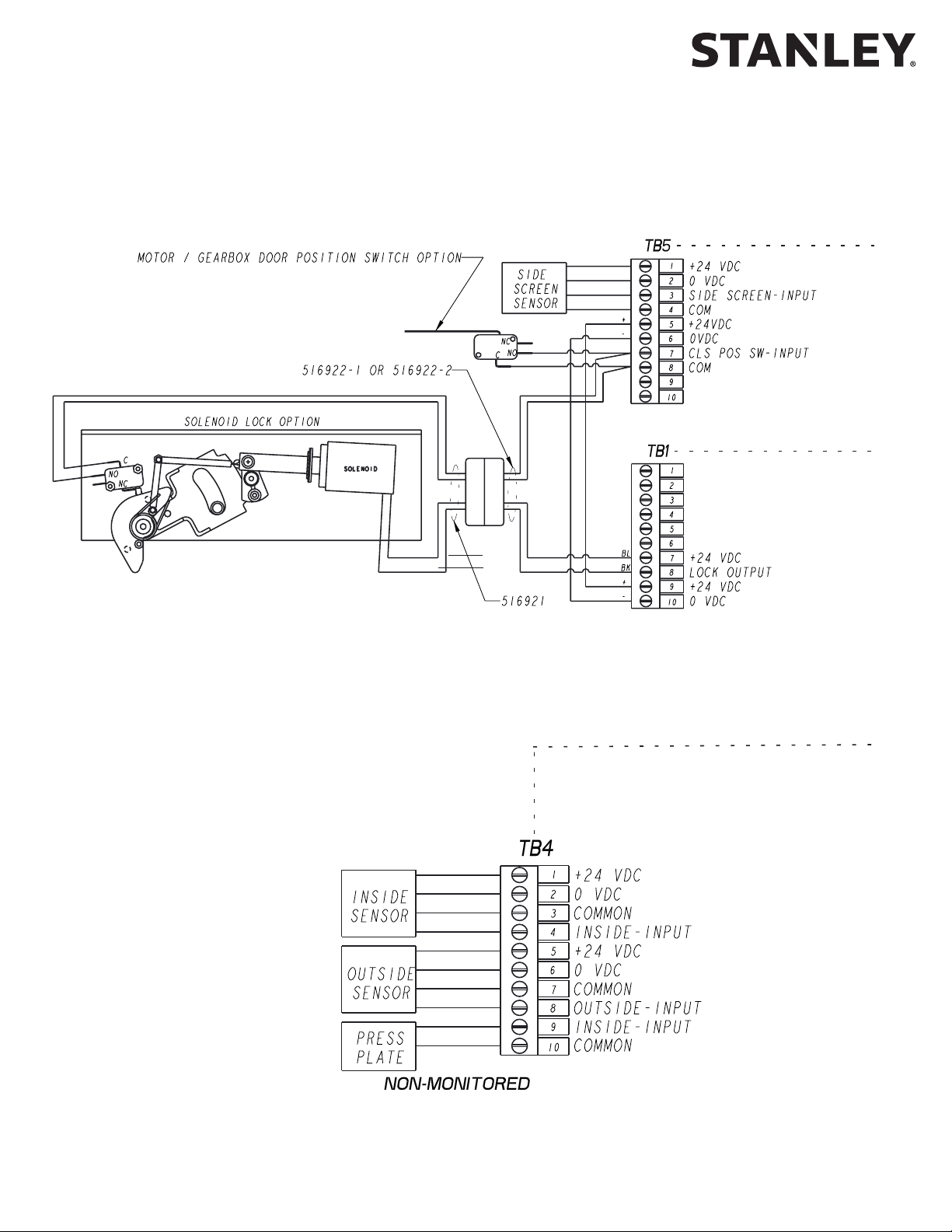
17 Terminal Block Connector TB5 Side screen sensor, door posion switch.
18 Terminal Block Connector TB4 Connecon point for INSIDE / OUTSIDE sensor and push plate.
All rights reserved. Reproduction
19 Terminal Block Connector TB3 Connecon point for StanguardTM, safety sensor and breakout switch.
not available.
to determine when to remove JP301 for monitored sensor installaons.
Using jumper wires across TB3 terminals 1 to 5 and 2 to 6,
internal 24 VDC supplies power to mulple external sensors.
Copyright 2019, Stanley Access Technologies, LLC.
in whole or in part without the express written permission of Stanley is prohibited.
01.25.2019
20 Document # 204144 REV B • www.stanleyaccess.com • 1.800.7.ACCESS
Page 21
iQ Control Box
Attachment 2
iQ System Wiring Diagram
(Sheet 1 of 10)
NOTE: JP 301 must be installed.
Copyright 2019, Stanley Access Technologies, LLC. All rights reserved. Reproduction
in whole or in part without the express written permission of Stanley is prohibited.
1.800.7.ACCESS • www.stanleyaccess.com • Document # 204144 REV B 21
01.25.2019
Page 22

Attachment 2
iQ System Wiring Diagram
(Sheet 2 of 10)
iQ Control Box
All rights reserved. Reproduction
Copyright 2019, Stanley Access Technologies, LLC.
in whole or in part without the express written permission of Stanley is prohibited.
01.25.2019
22 Document # 204144 REV B • www.stanleyaccess.com • 1.800.7.ACCESS
Page 23
iQ Control Box
Attachment 2
iQ System Wiring Diagram
(Sheet 3 of 10)
SEE NEXT PAGE
OR
Copyright 2019, Stanley Access Technologies, LLC. All rights reserved. Reproduction
in whole or in part without the express written permission of Stanley is prohibited.
1.800.7.ACCESS • www.stanleyaccess.com • Document # 204144 REV B 23
01.25.2019
Page 24

Attachment 2
iQ System Wiring Diagram
(Sheet 4 of 10
iQ Control Box
SEE PREVIOUS PAGE
OR
All rights reserved. Reproduction
Copyright 2019, Stanley Access Technologies, LLC.
in whole or in part without the express written permission of Stanley is prohibited.
01.25.2019
24 Document # 204144 REV B • www.stanleyaccess.com • 1.800.7.ACCESS
Page 25
iQ Control Box
Attachment 2
iQ System Wiring Diagram
(Sheet 5 of 10)
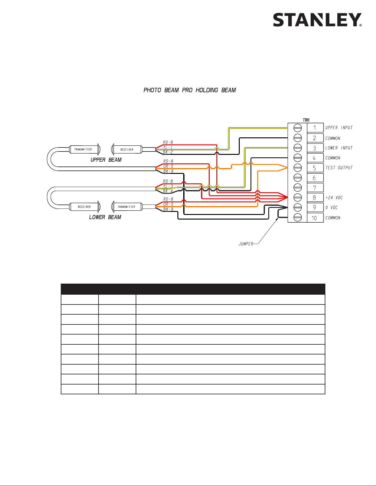
STANLEY PHOTO BEAM
On the iQ: Set INDEX 20 to VALUE 01 (Monitored Beam).
TB6 COLOR DUAL HOLDING BEAM WIRING
1 YL OUTPUT UPPER RECEIVER
2 BK (-) UPPER RECEIVER
3 YL OUTPUT LOWER RECEIVER
4 BK (-) LOWER RECEIVER
5 OR TRANSMITTER CONTROL LOWER AND UPPER
6 -- NO CONNECTION
7 -- NO CONNECTION
8 RD (+) ALL RECEIVERS AND TRANSMITTERS
9 BK (-) LOWER AND UPPER TRANSMITTERS, JUMPER TO TB6-10
10 BK JUMPER FROM TB6-9
Copyright 2019, Stanley Access Technologies, LLC. All rights reserved. Reproduction
in whole or in part without the express written permission of Stanley is prohibited.
1.800.7.ACCESS • www.stanleyaccess.com • Document # 204144 REV B 25
01.25.2019
Page 26

Attachment 2
iQ System Wiring Diagram
(Sheet 6 of 10)
iQ Control Box
All rights reserved. Reproduction
Copyright 2019, Stanley Access Technologies, LLC.
in whole or in part without the express written permission of Stanley is prohibited.
Program the OS-12 CT set to “D” - Acve High / N.C.
On the iQ: Set INDEX 20 to VALUE 01 (Monitored Beam).
01.25.2019
26 Document # 204144 REV B • www.stanleyaccess.com • 1.800.7.ACCESS
Page 27

iQ Control Box
Attachment 2
iQ System Wiring Diagram
(Sheet 7 of 10)
TB3 COLOR PHOTO BEAM PRO BREAKOUT BEAM
1 RD JUMPER FROM TB3-5
2 BK JUMPER FROM TB3-6
3 -- NO CONNECTION
4 -- NO CONNECTION
5 RD JUMPER FROM TB3-1, (+) RECEIVER AND TRANSMITTER
6 BK JUMPER FROM TB3-2, (-) RECIEVER AND TRANSMITTER
7 -- NO CONNECTION
8 -- NO CONNECTION
9 YL OUTPUT RECEIVER
10 -- NO CONNECTION
Copyright 2019, Stanley Access Technologies, LLC. All rights reserved. Reproduction
in whole or in part without the express written permission of Stanley is prohibited.
1.800.7.ACCESS • www.stanleyaccess.com • Document # 204144 REV B 27
01.25.2019
Page 28
Attachment 2
iQ System Wiring Diagram
(Sheet 8 of 10)
iQ Control Box
All rights reserved. Reproduction
Copyright 2019, Stanley Access Technologies, LLC.
in whole or in part without the express written permission of Stanley is prohibited.
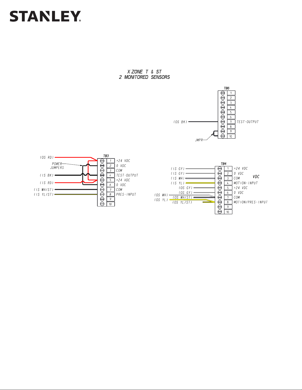
X-Zone ST
For Security Applicaons / 1-WAY
Key DIP Switch sengs: 10 and 11 DOWN; 12, 13, 14, 15 and 16 UP.
X-Zone ST and X-Zone (ST)
Key DIP Switch sengs: 10 and 11 DOWN; 12, 14 and 15 UP.
iQ
Remove JP301.
Set index 19 to Value = 00 (Sensor Monitoring with Threshold Control).
X-Zone T
Key DIP Switch sengs: 11 and 12 DOWN; 13 and 15 UP.
iQ
Remove JP301.
Set index 19 to Value = 03 (Monitored 2 Sensors).
NOTE:: The X-Zone ST will replace the X-Zone (ST) in 2019.
01.25.2019
28 Document # 204144 REV B • www.stanleyaccess.com • 1.800.7.ACCESS
Page 29

iQ Control Box
Attachment 2
iQ System Wiring Diagram
(Sheet 9 of 10)
X-Zone ST
For Security Applicaons / 1-WAY
Key DIP Switch sengs: 10 and 11 DOWN; 12, 13, 14, 15 and 16 UP.
X-Zone ST and X-Zone (ST)
Key DIP Switch sengs: 10 and 11 DOWN; 12, 14 and 15 UP.
iQ
Remove JP301.
Set index 19 to Value = 01 (Monitored 4 Sensors - Threshold Zone Control).
X-Zone T
Key DIP Switch sengs: 11 and 12 DOWN; 13 UP and 15 UP.
iQ
Remove JP301.
Set index 19 to Value = 05 (Monitored 4 Sensors).
Copyright 2019, Stanley Access Technologies, LLC. All rights reserved. Reproduction
in whole or in part without the express written permission of Stanley is prohibited.
NOTE: The X-Zone ST will replace the X-Zone (ST) in 2019.
1.800.7.ACCESS • www.stanleyaccess.com • Document # 204144 REV B 29
01.25.2019
Page 30

Attachment 2
iQ System Wiring Diagram
(Sheet 10 of 10)
iQ Control Box
All rights reserved. Reproduction
Copyright 2019, Stanley Access Technologies, LLC.
in whole or in part without the express written permission of Stanley is prohibited.
HR100 ST
Recommended DIP Switch sengs:
DIP Switch X: (2, 3, and 4 = UP) (1 = DOWN).
DIP Switch Y: (1, 2, 3 and 4 = UP)
DIP Switch Z: (1, 2, 3 and 4 = UP) (5 and 6 = DOWN).
{UP = OFF} {DOWN = ON}
iQ Sengs
Remove JP301.
Set index 19 to Value = 03 (Monitored 2 Sensors).
CAUTION: Tapered HR100 ST base plate must removed before sensor
is installed for threshold sensor detecon.
01.25.2019
30 Document # 204144 REV B • www.stanleyaccess.com • 1.800.7.ACCESS
Page 31

iQ Control Box
TB2
TB2
1
TB3
4
2
3
Attachment 3
iQ Terminal Block Connections -- TB1 through TB7
(Sheet 1 of 1)
2
4
6
8
5
9
7
10
1
TB7
5
3
8
6
7
9
10
VDC -
0
24 VDC +
EXT+
EXT-
COMMON (WH)
STANGUARD(GN)
EXT-
SEENOTE1
1
2
3
4
(ROTARYSWITCHWIRING)
COMMON (YL)
HOLD OPEN (BK)
1
COMMON (OR)
AUTOMATIC (RD)
3
2
4
COMMON (WH)
INT-
6
7
5
REDUCEDOPEN(GN)
ENTER-ONEWAY (BN)
6
7
5
BREAKOUT (GN)
OPTEXHOLDING BEAM (GN)
8
9
FIRE ALARM INPUT
8
9
COMMON (WH)
10
NOTE: Requires proper
setting of index 47 and 48.
Refer to Table 3 - Settings.
10
15 VDC +
1
TB6
PHOTO BEAM PRO UPPER RCVR
1
SEE NOTE 1SEE NOTE 1
VDC -
0
COMMON
COMMON
2
3
4
COMMON
PHOTO BEAM PRO LOWER RCVR
PHOTO BEAM PRO TEST OUTPUT
3
4
2
7
5
6
COMMON
OUT_SPARE2
7
5
6
COMMON
8
9
10
VDC -
0
24 VDC +
COMMON
8
9
10
(ROCKERSWITCHWIRING)
COMMON
HOLD OPEN (YL)
COMMON (OR)
AUTOMATIC (BN)
COMMON (BL)
COMMON(VI)
REDUCEDOPEN(VI )
ENTER-ONEWAY (BL)
EXT+
EXT-
EXT-
COMMON
SIDE SCREEN SENSOR
CH
VDC -
0
24 VDC +
INT-
COMMON
SEE NOTE 1
CLOSED POSITION SWIT
1
EXT+
2
EXT-
COMMON (WH)
EXT-
6
8
2
4
1
TB1
15 VDC +
5
3
SOLENOID LOCK (BL)
9
7
SOLENOID LOCK (BK)
10
TB TB54
VDC -
0
24 VDC +
POWER
INPUT
5
6
8
4
3
VDC -(BK)
0
24 VDC + (RD)
INSIDE SENSOR
COMMON (WH)
INT-
9
7
OUTSIDESENSOR(GN)
10
COMMON
PUSH PLATE
TO THE EXTERNAL POWER SUPPLY BUS (EXT).
NOTE 1. REMOVE JUMPERS ON TB3 IF EXTERNAL POWER SUPPLY IS USED.
JUMPERS ON TB3 CONNECT INTERNAL POWER SUPPLY (INT)
Copyright 2019, Stanley Access Technologies, LLC. All rights reserved. Reproduction
in whole or in part without the express written permission of Stanley is prohibited.
01.25.2019
1.800.7.ACCESS • www.stanleyaccess.com • Document # 204144 REV B 31
Page 32

iQ Control Box
Attachment 4
ANSI/BHMA and UL Compliance Requirements for Sliding Doors
(Sheet 1 of 3)
Final adjustment and proper operaon of the door system must be and shall be performed in the eld.
NOTE: These instrucons are for informaonal purposes and do not substute for review against the current
revision of the referenced standards. Where a requirement exists in mulple standards, such as the ANSI/BHMA
standard and the UL standard, the more restricve condion applies. Other local codes and re codes likely exist,
and must also be followed.
ANSI/BHMA A156.10 Sliding Door Systems
Sliding door systems must be installed and adjusted for compliance with the current version of ANSI/BHMA
A156.10, “American Naonal Standard for Power Operated Pedestrian Doors”.
Crical aspects of the installaon for compliance with ANSI/BHMA A156.10 include:
• Control mat size, layout, molding height, acve areas and sensivity.
• Sensor paern size, sensivity, and funcon.
• Knowing Act guidelines and secondary acvang zone.
• Entrapment protecon rules including door speeds, forces, and me delays.
• Signage. (Decals and applicaon instrucons are provided with the door system.)
NOTE: For Procare and Duracare series Automac series refer to the current version of ANSI/BHMA A156.38.
UL 325 Compliance
All power operated door systems must be installed in compliance with the current edion of UL 325, “Standard for
Safety for Door, Drapery, Gate, Louver, and Window Operators and Systems”.
Wiring
1. To reduce the risk of electric shock proper and reliable grounding is mandatory. See Main Power Wiring instruc-
All rights reserved. Reproduction
ons and Wiring Diagrams in this guide for grounding techniques.
2. Permanent wiring is to be employed as required by the Naonal Electrical Code and/or local codes.
3. Connecon of external devices is shown in the wiring diagrams and terminal block layouts elsewhere in this
guide. Refer to these gures for proper wiring of external devices to ensure compliance with UL 325.
Knowing Act
Doors acvated by a manual switch (Knowing Act switch in ANSI/BHMA terms) must have the switch installed
in a locaon from which operaon of the door can be observed by the person operang the switch and not
located in a positon where the user would be in the path of the moving door.
Copyright 2019, Stanley Access Technologies, LLC.
in whole or in part without the express written permission of Stanley is prohibited.
01.25.2019
32 Document # 204144 REV B • www.stanleyaccess.com • 1.800.7.ACCESS
Page 33

iQ Control Box
Attachment 4
ANSI/BHMA and UL Compliance Requirements for Sliding Doors
(Sheet 2 of 3)
To ensure that a sliding door operates in accordance with UL 325 entrapment protecon criteria the following must
be established:
• Manual opening force (sliding doors without breakout) or breakout force with power on or o must be less
then 50 lbf (222.4 N).
• Closing force must be less than 30 lbf (133.4 N).
• A closing sliding door must not develop kinec energy in excess of 2.5 -lbf (3.39 J). This is achieved by proper
seng of the closing speed. See secon entled “Closing Speed”.
• Maximum recommended door weight:
• Dura-Glide 5000 Series = 150 lbs (70 kg) per panel.
• Dura-Glide/Dura-Guard/Dura-Storm and similar 2000/3000 Series = 220 lbs (100 kg) per panel.
• IS10000/Double Diamond and similar Industrial Series = 300 lbs (90 kg) per panel
Closing Speed
Closing speed is measured over a travel distance of 2 or 3 feet. On smaller bi-part doors there may only be
2 feet of movement before the door system enters close-check (latch check). The me measurement should
start once the door has achieved closing speed, usually 6 inches from full open. Mark this point on the oor
with tape or other object. Measure from this point 2 or 3 feet toward the closed posion and mark the next
point. Use a stopwatch to measure the me it takes for the sliding panel to travel this distance during
normal closing cycles. Make sure the door system is not braking or entering close-check during the
measurement. Repeat the measurement 3 mes and use the average value. The allowed me for a
sliding panel to cover this distance during the closing cycle is given in the table below.
Door Weight
(pounds)
160 or less 2.0 3.0
161 to 180 2.1 3.2
181 to 200 2.2 3.3
201 to 220 2.3 3.5
221 to 240 2.4 3.7
241 to 260 2.5 3.8
261 to 280 2.6 4.0
281 to 300 2.7 4.1
Closing Time (seconds)
2 foot measurement
Closing Time (seconds)
3 foot measurement
NOTE: For low energy slide door applicaons refer to aachment 4 sheet 3 of 3.
1.800.7.ACCESS • www.stanleyaccess.com • Document # 204144 REV B 33
Copyright 2019, Stanley Access Technologies, LLC. All rights reserved. Reproduction
in whole or in part without the express written permission of Stanley is prohibited.
01.25.2019
Page 34

iQ Control Box
Attachment 4
ANSI/BHMA and IBC Compliance Requirements for
Low Energy Power Operated Sliding Doors
(Sheet 3 of 3)
To ensure that a Low Energy Power Operated Sliding Door operates in accordance with ANSI/BHMA and the
the IBC-2018, the following must be established:
• Acvaon of the door must be by a Knowing Act.
• The Opening Time (speed) of the Door(s) shall be adjusted so that the door(s) open at a speed of 12 inches
per second maximum, from fully closed to fully open.
• When powered open, the door shall remain at the fully open posion for not less than 5 seconds before
starng the closing cycle.
• The Closing Time (speed) of Door(s) shall be adjusted so that the door(s) close at a speed of 6 inches per
second maximum per leaf, from fully open to latch check.
• Latch check shall occur at no less than 2 inches from fully closed.
All rights reserved. Reproduction
• The force required to prevent a stopped door from opening or closing shall not exceed 15 lbf (67 N).
• The required Signage must be present.
NOTE: In special applicaons where safety sensors or secondary acvaon sensors are used on
a low energy door, refer to ANSI/BHMA A156.10 for guidance on sensor performance criteria
for the type of sensor selected.
Copyright 2019, Stanley Access Technologies, LLC.
in whole or in part without the express written permission of Stanley is prohibited.
01.25.2019
34 Document # 204144 REV B • www.stanleyaccess.com • 1.800.7.ACCESS
Page 35

iQ Control Box
Attachment 5
Troubleshooting Aid (Sheet 1 of 1)
Terminal and Pin Descripon State
TB1-8 Solenoid Lock Output Dark = Unlocked
w/o PCB, fail secure Dark = Unlocked
w/o PCB, fail safe Dark = Locked
NOTE: Black color indicates a low signal (Approx. 0 VDC).
Rotary Function Switch States for TB2
Hold
Open
TB2-1
TB2-3
TB2-5 Don’t Care Don’t Care
TB2-7
Closed
Locked
Automac One Way Reduced Reduced
One Way
Rocker Function Switch States for TB2
Hold
Open
TB2-1
TB2-3
TB2-5 Don’t Care Don’t Care
TB2-7 Don’t Care Don’t Care
Terminal and Pin Descripon State
TB3-4 StanguardTM Input/Output Dark = triggered or detecng
TB3-8 & TB4-8
Non-Monitored Holding Beam Input Input
and Outside Sensor (connected internally)
TB3-9 Breakout Input Dark = no breakout
TB4-4 & TB4-9
TB4-8 & TB3-8
TB4-9 & TB4-4
Inside Sensor Input and
Push Plate Input (connected internally)
Inside Presence Sensor Input and
Holding Beam Input (connected internally)
Push Plate Input and
Inside Sensor Input (connected internally)
TB5-3 Side Screen Sensor Input Dark = detecng
TB5-7 Closed-Door Posion Switch Input Dark = closed
TB5-10 Spare
TB6-1 Monitored Beam Upper Holding Beam Dark = unobstructed White = detecng
TB6-3
Monitored Beam Lower Holding Beam
TB6-5 Photo Beam Pro Test Output Dark = tesng
TB6-7 Sensor Test Output Dark = normal operaon
Closed
Locked
Automac One Way Reduced Reduced
One Way
Dark = detecng
Dark = detecng
Dark = detecng
Dark = detecng
Dark = unobstructed White = detecng
Copyright 2019, Stanley Access Technologies, LLC. All rights reserved. Reproduction
in whole or in part without the express written permission of Stanley is prohibited.
01.25.2019
1.800.7.ACCESS • www.stanleyaccess.com • Document # 204144 REV B 35
Page 36

Attachment 6
iQ Troubleshooting Aid
(Sheet 1 of 1)
Symptom Remedy
Use best pracces to troubleshoot using handheld device and
Door does not close and/or
Status code displays ho/E2
NOTE: E2 indicates door held open by any sensor
input other than Hold Open Switch on TB-2.
Handheld will not update rmware Controller is not displaying 00. Re-FIS the door.
Door hits Open Stop/full open bumper Increase the Open Check Length (Index 3).
Door moon is not the same as the MC521/
MC521PRO for the same sengs
Status code displays E3
Status code displays E4
Status code displays F0-F1, F6-F7 Verify sensor wiring and safety logic seng.
Status code displays F2-F3
provided wiring diagrams.
Check hold beam type (index 20). Monitored beams should
be set to “Monitored Beam” and non-monitored beams
should be set to “Non-monitored Beam.”
Reference latest Photo Beam Pro Troubleshoong Tech Tip.
Parameters value for the iQ are not the same as MC521/
MC521PRO. Refer to Table 3.
Check mechanical issues, components.
Re-do rst installaon sequence (FIS).
Verify sensor wiring and safety logic seng.
Monitored beam Failure. Verify proper wiring and “holding
beam type”(index 20 = appropraite seng, Monitored Beam
or Non-Monitored Beam.
iQ Control Box
Door moves slowly on one cycle.
Status code displays 33 or 34 or 36 momentarily
(3 seconds).
Door moves slowly on several cycles.
All rights reserved. Reproduction
Status code displays 33 or 34 or 36 on
slow cycles.
Door tuning issues
Copyright 2019, Stanley Access Technologies, LLC.
in whole or in part without the express written permission of Stanley is prohibited.
01.25.2019
Reference latest Photo Beam Pro Troubleshoong Tech Tip.
Note it. No acon required.
1. Reset Power.
2. If code does not clear, Call Tech Support.
Refer to parameter descripons for useful adjustments.
36 Document # 204144 REV B • www.stanleyaccess.com • 1.800.7.ACCESS
Page 37

iQ Control Box
Attachment 7
Fine Tuning Slide Doors
(Sheet 1 of 2)
Tuning the Stanley Automatic Door
Match your actual door to one from the list of doors described in the aachment. Start by installing these sengs.
Use the guide below to make adjustments to these sengs.
If the door:
OPENS TOO SLOWLY
If it is too slow
Increase Open Speed. Maximum seng is 99 with keypad or
125 with handheld.
Increase Open Torque
If it is too slow
NOTES: Max Values go to 125 via handheld.
Open Torque is also used to set the door open force.
HITS THE OPEN STOP
When the door braking and moon are under control, reduce the Open Check length as desired.
CLOSES TOO SLOWLY
If it is too slow
If it is too slow
NOTE: Close Torque is also used to set the door closing force.
Close Speed and Close Force cannot exceed the value specied by ANSI/BHMA 156.10.
Increase Open Acceleration
Increase Open Stop to 8 and Open Check Length to 45
Increase Open Brake unl there is good braking.
Increase or decrease unl there is good moon
entering and in Open Check.
Increase Close Speed to 16
Increase Close Torque
Increase Close Acceleration
Copyright 2019, Stanley Access Technologies, LLC. All rights reserved. Reproduction
1.800.7.ACCESS • www.stanleyaccess.com • Document # 204144 REV B 37
in whole or in part without the express written permission of Stanley is prohibited.
01.25.2019
Page 38

Attachment 7
Fine Tuning Slide Doors
(Sheet 2 of 2)
Tuning the Stanley Automatic Door (Continued).
Match your actual door to one from the list of doors described in the aachment. Start by installing these
sengs. Use the guide below to make adjustments to these sengs.
If the door:
HITS THE CLOSE STOP too hard
Set Close Check Length to 50. Set Close Press to 1 and test.
Increase the Close Brake seng unl there is good braking.
Increase or decrease Close Check unl there is smooth moon entering and in Close Check.
STALLS during opening without any
mechanical reason. . .
Connues to stall and it seems
to happen at the transion
from Open Brake to Open Check
STALLS during closing without any
obvious reason. . .
Connues to stall and it seems to
happen at the transion to Close
Check
SPEEDS UP during Close Check
Increase Obstruction Time from .5 seconds to 1.0 seconds
Make small increases to Open Brake.
Increase Obstruction Time
Increase Close Check one count at a me
Close Check Speed is set too high. Reduce Close Check one count at a
me unl door moon is suitable.
Stanley Access Technologies
65 Scott Swamp Road
Farmington, CT 06032
Document # 204144 REV B • www.stanleyaccess.com • 1.800.7.ACCESS
 Loading...