

Page 1

Stanley Access Technologies
Quick-Reference Guide
Dura-Glide™ 2000AG All-Glass Sliding Door
Installation Instructions
Quick-Reference Guide
203729
Rev. E, 11/20/2018
Prohibition on Copying
Any unauthorized reproduction, disclosure or distribution of copies by any person of any
portion of this work may be a violation of copyright law of the United States of America
and other countries, could result in the awarding of statutory damages of up to $250,000
(17 USC 504) for infringement, and may result in further civil and criminal penalties. All
rights reserved.
Page 2

Stanley Access Technologies
Quick-Reference Guide
TABLE OF CONTENTS
1. PURPOSE ...................................................................................................................................................... 2
1.1 Discussion .................................................................................................................................................... 2
1.2 Applicability ................................................................................................................................................ 2
2. PREREQUISITES ......................................................................................................................................... 3
3. INSTALLATION INSTRUCTIONS ............................................................................................................ 4
3.1 Installing the Header and Jambs .................................................................................................................. 4
3.2 Installing the Top and Bottom Rails onto the Glass Panel .......................................................................... 4
3.3 Installing the O-Panel Breakout Switch ...................................................................................................... 5
3.4 Installing the Lag Bolts ................................................................................................................................ 6
3.5 Installing the O-Panel(s) .............................................................................................................................. 6
3.6 Installing the SX Panel(s) ............................................................................................................................ 7
3.7 Installing the Weatherstripping.................................................................................................................... 9
3.8 Adjusting the SX Panels ............................................................................................................................ 10
3.9 Adjusting Belt Tension .............................................................................................................................. 11
3.10 Adjusting the Full-Open Bumper Stops .................................................................................................. 12
3.11 Adjusting the SX Panel Emergency Egress Breakout Detents ................................................................ 12
3.12 Adjusting the SX Panel Sag ..................................................................................................................... 14
3.13 Wiring the Doorway Holding Beams ...................................................................................................... 14
3.14 Installing the SU-100 Motion Sensors ..................................................................................................... 15
3.15 Closing Out .............................................................................................................................................. 15
3.16 Replacement Parts ................................................................................................................................... 15
Attachments
Attachment 1, Documents, Definitions, Speci al Tools, Equipment, Materials, and Consumables .................... 16
Attachment 2, Glass Panel Specifications ........................................................................................................... 17
Attachment 3, Replacement Parts ....................................................................................................................... 18
203729
Rev. E, 11/20/18
© 2018, THE STANLEY WORKS. ALL RIGHTS RESERVED. 1 of 18
Page 3
1. PURPOSE
1.1 Discussion
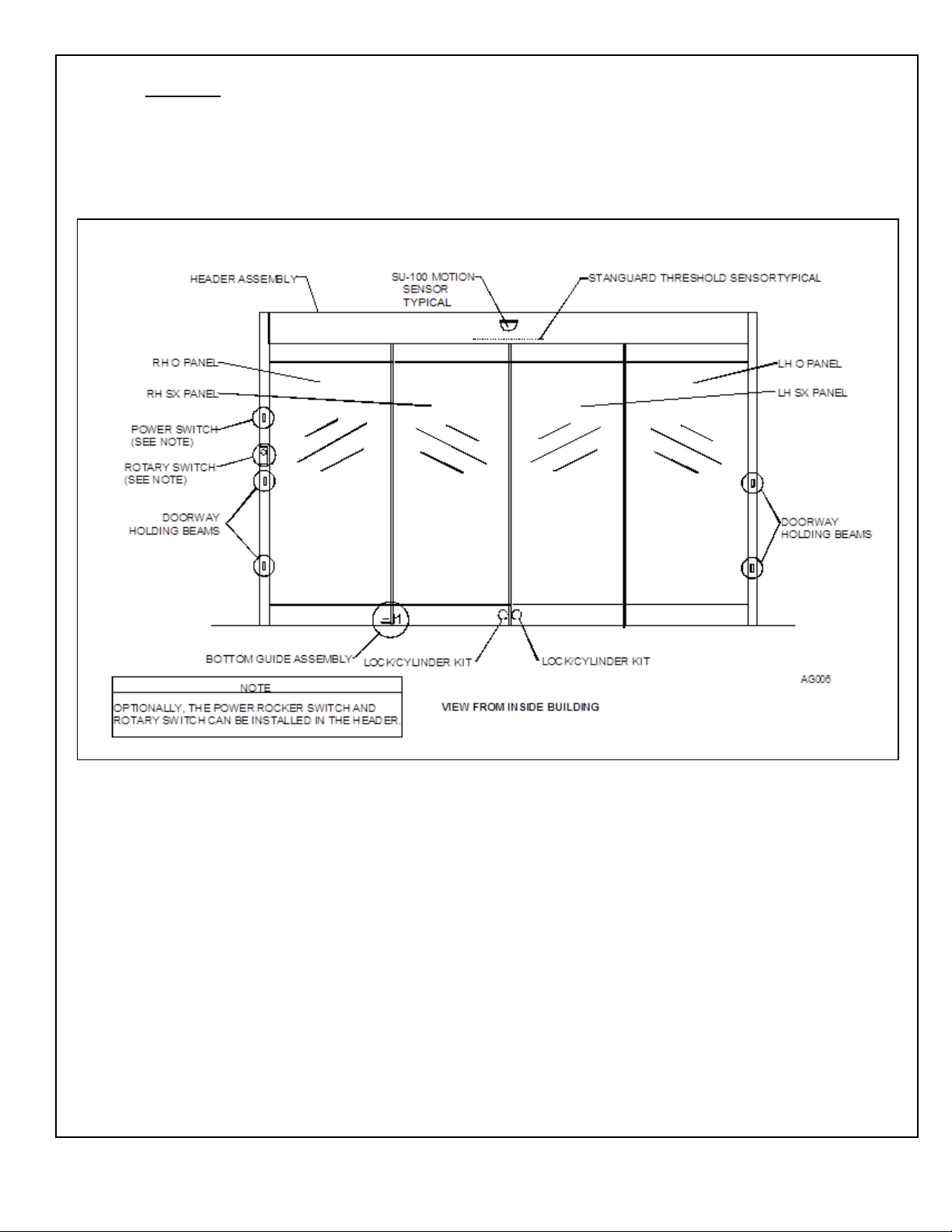
This manual provides installation instructions for the Stanley Dura-Glide 2000AG Series sliding
door system. The AG Series features all-glass SX- and O-panels. The package includes a
breakout feature and the items shown in Figure 1.
Figure 1. All-Glass Door
1.2 Applicability
This manual is applicable to the Stanley Dura-Glide 2000 AG Series sliding door system. This
manual does not cover retrofit of an existing door system.
203729
Rev. E, 11/20/18
© 2018, THE STANLEY WORKS. ALL RIGHTS RESERVED. 2 of 18
Page 4

2. PREREQUISITES
2.1 Electrical power to the door has been deenergized before performing installation or maintenance.
2.2 Protective barrier (caution/warning tape) has been set up to prevent unauthorized access to work
area.
2.3 The area has been cleared of all obstructio ns.
2.4 Attachment 1 has been reviewed for the fol lowing:
• Definitions of the terms used in this procedure
• A listing of the documents, special tools and equipment, materials, and consumables used in
this procedure.
2.5 Attachment 3 replacement parts list has been r eviewed.
203729
Rev. E, 11/20/18
© 2018, THE STANLEY WORKS. ALL RIGHTS RESERVED. 3 of 18
Page 5

3. INSTALLATION INSTRUCTIONS
NOTE
These instructions are intended to supplement the other installation instructions supplied with this package.
3.1 Installing the Header and Jambs
3.1.1 Refer to Stanley Access Technologies document No. 203590, “Dura-Glide 2000
Installation Manual,” and INSTALL the header and jambs.
3.2 Installing the Top and Bottom Rails onto the Glass Panel
WARNING
To prevent injury, two people are required to lift and handle the glass panels.
To prevent damage to the glass panels from scratching, saw horse working surfaces should be protected
with carpeting or some other soft material.
NOTE
The instructions for installing the top and bottom rails onto the glass are the same for the O panels and SX panels.
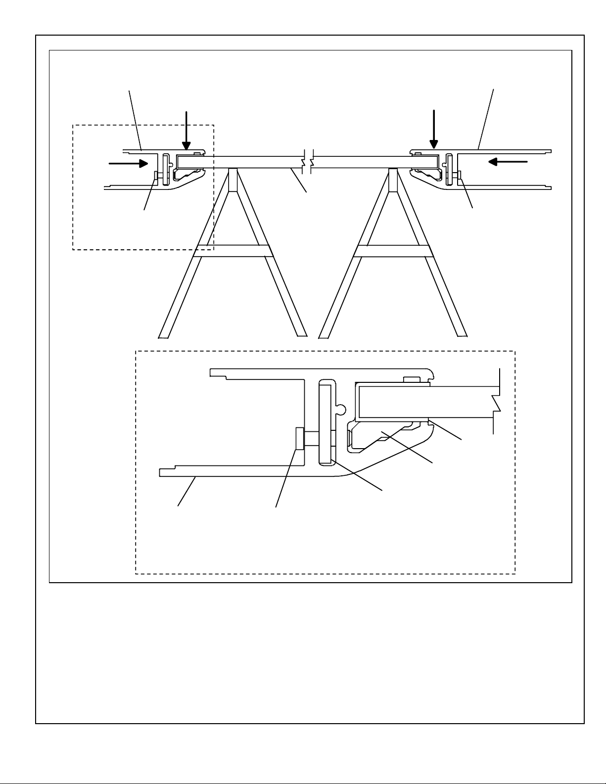
3.2.1 Refer to Figure 2, and carefully POSITION glass panel onto saw horses.
3.2.2 INSTALL rubber gasket onto top of glass panel, and ENSURE the following:
• Rubber gasket is centered along the width of the glass.
• Rubber gasket is fully seated against the top of the glass.
• Tech Tip: Use painter’s tape to keep rubber gasket in place.
3.2.3 With flat side of wedge facing upward, SLIDE wedge into side of rail.
3.2.4 SLIDE plate into side of rail.
3.2.5 With flat side of rail facing upward, POSITION rail over rubber gasket and glass
panel.
5
3.2.6 INSTALL, but do not tighten ¼ -20 X
/8″ cap screws into bottom of rail and plate.
3.2.7 ALIGN rail onto glass so that the leading ed ge of the glass butts against the end cap.
3.2.8 While pushing rail down and toward bottom edge of glass, evenly TORQUE ¼ -20 X
5
/8″ cap screws to 80 in-lbs. REMOVE or TRIM painter’s tape as need ed.
3.2.9 REPEAT Section 3.2 for each rail on O and SX panels.
203729
Rev. E, 11/20/18
© 2018, THE STANLEY WORKS. ALL RIGHTS RESERVED. 4 of 18
Page 6
FLAT SIDE OF TOP
RAIL FACING UP
FLAT SIDE OF BOTTOM
RAIL FACING UP
PUSH
EVENLY TORQUE CAP
SCREWS TO 80 IN-LBS
PUSH
GLASS PANEL
PUSH
PUSH
EVENLY TORQUE CAP
SCREWS TO 80 IN-LBS
AG010
RUBBER
GASKET
WEDGE
BOTTOM RAIL
PLATE
1/4-20 X 5/8" CAP SCREW
(EVENLY TORQUE TO 80 IN-LBS)
SEE DETAIL A
DETAIL A: RAIL ATTACHMENT
Figure 2. Installing the Rails onto the Glass Panel
3.3 Installing the O-Panel Breakout Switch
3.3.1 Refer to Stanley Access Technologies document No. 203590, “Dura-Glide 2000
Installation Manual,” and INSTALL the O-panel breakout switch.
203729
Rev. E, 11/20/18
© 2018, THE STANLEY WORKS. ALL RIGHTS RESERVED. 5 of 18
Page 7

3.4 Installing the Lag Bolts
3.4.1 Refer to Figure 3 and, using a plumb bob from the header, MARK the locations for the
two O panel lag bolts. Note the two block mounting options shown in Figure 3.1.
3
3.4.2 INSTALL the two
3.4.3 INSTALL the two
/8″ X 2″ expansion shields.
3
/8″ X 2″ lag bolts.
3.5 Installing the O-Panel(s)
3.5.1 Refer to Section 3.2, and INSTALL top and bottom rails onto O panel glass.
3.5.2 Refer to Figure 3, and INSTALL O-panel pressure-sensitive pile on trailing glass pane.
3.5.3 Refer to Stanley Access Technologies document No. 203590, “Dura-Glide 2000
Installation Manual,” and INSTALL the O-panel(s).
203729
Rev. E, 11/20/18
© 2018, THE STANLEY WORKS. ALL RIGHTS RESERVED. 6 of 18
Page 8

3.6 Installing the SX Panel(s)
3.6.1 Refer to Section 3.2, and INSTALL top and bottom rails onto SX panel glass.
3.6.2 Figure 4, and INSTALL the Door holder assembly as follows: a. Using the supplied ¼″-20 X 2″ socket head capscrews and tapped holes, SECURE
damper assembly to top rail of door panel.
Figure 4. Installing the Door Holder Assembly
b. Using the supplied ¼″-20 X 1″ socket head capscrews, SECURE door holder
assembly to header.
3.6.3 Refer to Figure 5, and LOOSEN the nuts securing the load wheels and anti-riser
wheels to the hanger.
203729
Rev. E, 11/20/18
© 2018, THE STANLEY WORKS. ALL RIGHTS RESERVED. 7 of 18
Page 9

Figure 5. Setting the Load Wheels and Anti-Riser Wheels
3.6.4 Using an Allen wrench SET the load wheels to th e midrange of travel position in the
hanger. In this position, the top of the load wheel is
1
/16 ″ below the top of the hanger.
3.6.5 SET the anti-riser wheels so that the top of each wheel is flush with the top of the
hanger.
3.6.6 TIGHTEN the nuts securing the load wheels and anti-ri ser wheels to the hanger.
3.6.7 Refer to Figure 6, and INSTALL the bottom guide to the SX panel bottom rail.
WARNING
Whenever the door anti-riser wheels are not set, there is a possibility that the panel could fall off the hanger
track. Use extreme caution when handl ing the panels.
3.6.8 Refer to Figure 7, and INSERT the SX panel bottom guide into the O panel bottom
rail.
3.6.9 Carefully LIFT the SX panel and POSITION the panel onto the header track.
3.6.10 SET the anti-riser wheels so that there is a 1/64″ to 1/32″ gap between the top of each
wheel and the track.
3.6.11 REPEAT Section 3.6 for the opposite SX panel.
203729
Rev. E, 11/20/18
© 2018, THE STANLEY WORKS. ALL RIGHTS RESERVED. 8 of 18
Page 10

Figure 6. Hanging the SX Panel on the Header Track
3.7 Installing the Weatherstripping
3.7.1 CLEAN edges of the O & SX panels using glass cleaner. CLEAN exterior surface of
the lead SX shoes & trail edge O shoes.
3.7.2 Refer to Figure 7 and PRESS pressure-sensative gray pile with clear PVC housing
onto the leading edges of the SX panels. Peel the adhesive liner from the inner
channel as needed.
3.7.3 Refer to Figure 7 and PRESS pressure-sensative gray pile with clear PVC housing
onto the trailing edges of the O panels. Peel the adhesive liner from the inner channel
as needed.
3.7.4 With brush facing the exterior of the building, INSTALL 90° clear extrusion with
weatherstripping onto leading edge of O panels.
3.7.5 With brush facing the interior of the building, INSTALL 90° clear extrusion with
weatherstripping onto trailing edge of SX panels.
3.7.6 Locate the gray self-adhesive pile from the hardware kit and cut to length. Peel the
self-adhesive backing and PRESS on the pile to the lead edges of the SX shoes.
ALIGN the pile so it contacts each other when the panels are in the closed position.
ENSURE the pile does not prevent the panels from closing properly.
203729
Rev. E, 11/20/18
© 2018, THE STANLEY WORKS. ALL RIGHTS RESERVED. 9 of 18
Page 11

3.7.7 Locate the gray self-adhesive pile from the hardware kit and cut to length. Peel the
self-adehsive backing and PRESS on the pile to the trail edges of the O shoes. ALIGN
the pile so it contacts the jambs when the panels are in the closed posi t ion.
Figure 7. Weatherstripping Installation
3.8 Adjusting the SX Panels
3.8.1 Refer to Figure 5, and ADJUST SX panel height as follows: a. LOOSEN the nuts securing the upper load wheels to the hanger.
NOTE
Each load wheel is an eccentric that permits adjustment of the threshold/track-to-panel gap. The total
adjustment available from the load wheels is approximately 5/16”.
b. Using an Allen wrench, TURN the load wheels un til the following occur:
• Threshold/track-to-panel gap is even across the entire bottom of the door
panel.
• The stiles of both door panels meet and are parallel with no gap at the top or
bottom.
c. WHEN adjustment is complete, TIGHTEN nuts securing load wheels to hanger.
NOTE
The anti-riser adjustment is performed to prevent the door panel from moving upward. The anti-riser track
serves as a roller surface for the anti-riser wheels.
3.8.2 ADJUST the anti-risers as follows:
203729
Rev. E, 11/20/18
© 2018, THE STANLEY WORKS. ALL RIGHTS RESERVED. 10 of 18
Page 12

28"
(SEE DETAIL B)
BELT
LONG
BRACKET
AG016
DIM. A
SHORT
BRACKET
GEAR REDUCER
DRIVE PULLEY
BELT DEFLECTION MEASUREMENT
DETAIL B
2
15
/16" TO 3
1
/16"
OPTIONAL
GEAR REDUCER
(SEE DETAIL A)
IDLER PULLEY
TENSION
ADJUSTING
SCREW
CLAMP
ANCHOR
DETAIL A
IDLER PULLEY AND BELT
TENSIONIN G ASSEMBLY
DIM. B
a. LOOSEN nuts securing the anti-riser wheels to the hanger.
b. SLIDE the anti-riser wheels upward in the hanger until there is a
between the top of the anti-riser wheels and the bottom of the anti-riser track.
c. TIGHTEN the nuts securing the anti-riser wheels to the hanger.
3.9 Adjusting Belt Tension
3.9.1 Refer to Figure 8, and facing cover side of header, OPEN doors until "Dimension B"
between short bracket and center of gear reducer drive pulley is 28 inches.
Figure 8. Adjusting Belt Tension
1
/64-to 1/32-inch gap
3.9.2 At the center of "Dimension B", HANG an 1
1
/2 lb. weight (or 12-inch crescent wrench)
from lower portion of belt.
3.9.3 MEASURE "Dimension A" from top of belt to bottom of belt
CAUTION
Over long spans, some belt deflection is required. To prevent damage to bearings and gear reducer, belt
must not be over-tightened.
3.9.4 IF "Dimension A" is not 215/16 to 31/16 inches, PERFORM the following:
203729
Rev. E, 11/20/18
© 2018, THE STANLEY WORKS. ALL RIGHTS RESERVED. 11 of 18
Page 13

GND
BUMPER STOP
(TYPICAL)
LOCKNUT
AG022
a. LOOSEN fastener(s) securing left gear reducer/idler pulley to header mounting
track.
b. TURN belt tension adjusting screw as necessar y to achieve proper belt deflection.
c. WHEN belt tension is fully adjusted, TIGHTEN fa stener(s) securing left gear
reducer/idler pulley to header mounting track.
3.10 Adjusting the Full-Open Bumper Stops
3.10.1 Refer To Figure 9, and LOOSEN bumper stop locknut.
Figure 9. Adjusting the Full-Open Bumper Stops
3.10.2 THREAD bumper stop to full-in position.
3.10.3 Manually OPEN doors to full open position, and TURN bumper stop as necessary to
ensure both SX panels contact bumper sto ps at the same time.
3.10.4 WHEN adjustment is complete, TIGHTEN bumper stop locknuts.
3.11 Adjusting the SX Panel Emergency Egress Brea kout Detents
NOTE
1. Breakout detents are factory set to average requirements. If more or less breakout force is required to
open door, the breakout detents can be adjusted.
2. During door installation, the breakout detents are set tight to prevent the door from swinging out and
being damaged. During door tune-in, the breakout detents must be readjusted.
3.11.1 BREAK OUT panel.
203729
Rev. E, 11/20/18
© 2018, THE STANLEY WORKS. ALL RIGHTS RESERVED. 12 of 18
Page 14

3.11.2 Refer To Figure 10, and LOOSEN two fasteners in bottom of detent block.
Figure 10. Adjusting Emergency Egress Breakout Detents
3.11.3 REMOVE end cap and detent block from hanger.
3.11.4 INSTALL weather-strips in exterior and interior channel of hanger and CUT weather-
strip to length.
NOTE
Turning adjusting screw clockwise increases the force required to break out door. Turning adjusting screw
counterclockwise decreases the force required to break out door.
3.11.5 TURN adjusting screw in top of detent block as necessar y to ensure door will be tight.
3.11.6 SLIDE detent block and end cap into hanger, and ENSURE detent block is aligned with
clearance slot in door.
3.11.7 TIGHTEN two fasteners in bottom of detent block.
3.11.8 With "TOP" indication facing upward, POSITION end cap over hanger.
3.11.9 TIGHTEN fastener securing end cap to detent block.
3.11.10 APPLY pressure-sensitive foam to end cap.
203729
Rev. E, 11/20/18
© 2018, THE STANLEY WORKS. ALL RIGHTS RESERVED. 13 of 18
Page 15

3.12 Adjusting the SX Panel Sag
3.12.1 IF SX panel sag adjustment is required, refer to Figure 11, and shim to ADJUST panel
sag.
Figure 11. Adjusting SX Panel Sag
3.13 Wiring the Doorway Holding Beams
3.13.1 Refer To doorway holding beam manufacturer’s instructions and CONNECT doorway
holding beam wiring.
203729
Rev. E, 11/20/18
© 2018, THE STANLEY WORKS. ALL RIGHTS RESERVED. 14 of 18
Page 16

3.14 Installing the SU-100 Motion Sensors
3.14.1 Refer to Stanley Access Technologies document No. 203957, “SU-100 Motion Sensor
Installation and Operation,” and INSTALL the two SU-100 motion sensors.
3.15 Closing Out
3.15.1 Refer to the following and TUNE-IN door:
• Stanley Access Technologies document No. 204003, “MC521 Controller
Installation and Operation Manual”
• Stanley Access Technologies document No. 203957, “SU-100 Motion Sensor
Installation and Operation”
• Stanley Access Technologies document No. 203768, “Stanguard Threshold
Sensor Installation and Operation”
3.16 Replacement Parts
3.16.1 Refer to Attachment 3 for a listing of replacement parts.
203729
Rev. E, 11/20/18
© 2018, THE STANLEY WORKS. ALL RIGHTS RESERVED. 15 of 18
Page 17

• Caulking gun
• Plumb bob
• Combination squar e
• Saw horses (with protected working surface)
Concrete drill bits
Screwdriver kit
• Electric drill
• Tape measure
hex drive)
• Concrete expansion shields
• Lag bolts
Clean rags
Silicone caulk
• Glass cleaner
• Painter’s tape
Attachment 1
Documents, Definitions, Special Tools, Equipment, Materials, and Consumables
(Sheet 1 of 1)
Documents
• Stanley Access Technologies document No. 203590, “Dura-Glide 2000 Installation Manual”
• Stanley Access Technologies document No. 204003, “MC521 Controller Installation and Operation
Manual”
• Stanley Access Technologies document No. 203957, “SU-100 Motion Sensor Installation and
Operation”
• Stanley Access Technologies document No. 203768, “Stanguard Threshold Sensor Installation and
Definitions
Special Tools and Equipment (including, but not limited to)
Operation”
• None
•
•
• Metal drill bit set • Torque wrench capable of 80 in lbs (with a 5/
Materials (including, but not limited to)
Consumables (including, but not limited to)
•
•
″
32
203729
Rev. E, 11/20/18
© 2018, THE STANLEY WORKS. ALL RIGHTS RESERVED. 16 of 18
Page 18

Note
Criteria
Specification
1
Thickness “T”
1.750" (without cladding) 44.5 mm
2
Glass Thickness
1/2" 12.7 mm
3
Glass Color
Color to be specified on the order.
specifications DD-G-001403 and DD-G-451d.
specification DD-G-001403.
buildings as described in ANSI Z97.1-1975.
7
Door Weight
Weight of door shall not exceed 220 lbs 100 kg
2
Attachment 2
Glass Panel Specifications
(Sheet 1 of 1)
The SX- and O-panels (provided by others) must meet the following specifications.
The panel widths and panel heights shown are to be specified on the order. To determine these dimensions
for standard size packages, see the Archit ectural Specifier sheets included in these instructions.
4 Temper Specification Glass shall be fully tempered and shall meet or exceed Federal
5 Warpage Glass warpage shall not exceed the tolerance specified in Federal
6 Performance Glass shall comply with the requirements in the performance
specifications and methods of test for safety glazing materials used in
The product of door weight (lbs) times the door width (inches) divided by
2 shall not exceed 5000 in. lbs.
Example:
If door weight = 200 lbs
5
And door width = 42
/16"
Then: 200 X 42.313 = 4231 in. lbs
2
OR
Kgs times the door width (m) divided by 2 shall not exceed 565 Nm
Metric Example:
If door weight = 100 kg
And door width = 1.1 m
Then: 100 X 1.1 X 9.8 = 539 Nm
203729
Rev. E, 11/20/18
© 2018, THE STANLEY WORKS. ALL RIGHTS RESERVED. 17 of 18
Page 19

Part No.
Quantity
Description
412199
8 FT
VINYL/PILE-SX PANEL-2000AG
417628
PER FT.
GASKET-AG SHOE
517004-1 (3,M)
1
END CAP-ANGLE SX RAIL-AG
517004-2 (3,M)
1
END CAP-ANGLE SX RAIL-AG
517006-1 (3,M)
1
END CAP-RH-SX RAIL-AG
517006-2 (3,M)
1
END CAP-LH-SX RAIL-AG
517007-1 (3,M)
1
ENDCAP-RH-"O"TOP RAIL-2000AG
517007-2 (3,M)
1
ENDCAP-LH-"O"TOP RAIL-2000AG
517008-1 (3,M)
1
END CAP-RH- ‘O’ BOTTOM RAIL-AG
517008-2 (3,M)
1
END CAP-LH- ‘O’ BOTTOM RAIL-AG
411624-4
PER FT.
PILE-ADHESIVE BACKED-GRAY
413268
PER FT.
SEAL-BRUSH-1 ¼” BLACK AG
413269
PER FT.
EXTR –SEAL AG
Attachment 3
Replacement Parts
(Sheet 1 of 1)
203729
Rev. E, 11/20/18
© 2018, THE STANLEY WORKS. ALL RIGHTS RESERVED. 18 of 18
 Loading...