

Page 1
Donard Solid Fuel Cooker
To ensure safety, satisfaction and maximum service, this Cooker should be installed by a suitably qualified
and competent person. The provision of a Central Heating facility, requires that the hot water systems
involved, conform fully to good plumbing practice and established standards.
INSTALLATION AND OPERATING INSTRUCTIONS
The manufacturers reserve the right to make alterations to design, materials or construction for manufacturing or other reasons subsequent to
publication.
Page 2

TABLE OF CONTENTS
Page No.
1. Operating Instructions ...................................................................................................................... 3
2. Schematic ..........................................................................................................................................3
3. Control of Substances........................................................................................................................3
4. Summer Operation.............................................................................................................................3
5. Specification ..................................................................................................................................... 4
6. Technical Data....................................................................................................................................4
7. Installation ........................................................................................................................................ 5
8. Pre-Installation Check - Location.......................................................................................................5
9. Hearth Construction .......................................................................................................................... 5
10. Chimney /Flues ................................................................................................................................ 5
11. Flue Box ........................................................................................................................................... 6
12. Flue Pipes/Connections .................................................................................................................... 6
13. Draught Requirements ..................................................................................................................... 6
14. Down Draughts ................................................................................................................................ 6
15. Cooker Clearance ............................................................................................................................ 6
16. Plumbing .......................................................................................................................................... 7
17. Regulations ...................................................................................................................................... 7
18. Boiler Output .................................................................................................................................... 7
19. Gravity Circuit .................................................................................................................................. 7
20. Exploded View ..................................................................................................................................8
21. Injector Tee ...................................................................................................................................... 9
22. Water Circuit Temperature ............................................................................................................... 9
23. Pipe Thermostat ............................................................................................................................... 9
24. Fuels ................................................................................................................................................ 9
25. Secondary Air Pipe .......................................................................................................................... 9
26. Circulating Pump ............................................................................................................................. 9
27. Inhibitors.............................................................................................................................................9
28. Operation ....................................................................................................................................... 10
29. Lighting The Fire ............................................................................................................................ 10
30. Fuelling .......................................................................................................................................... 10
31. Condensation ................................................................................................................................. 10
32. External Riddling ............................................................................................................................ 10
33. Ash Removal .................................................................................................................................. 11
34. Ash Pan .......................................................................................................................................... 11
35. Thermostat with Manual Override .................................................................................................. 11
36. Overnight Burning .......................................................................................................................... 11
37. Fire Door Spin Valve ...................................................................................................................... 11
38. Ash Door Spin Valve ...................................................................................................................... 12
39. Boiler Insulating Plate ......................................................................................................................12
40. Summer Grate & Heat Shields ...................................................................................................... 12
41. Assembly..........................................................................................................................................12
42. Hotplate Insulating Covers ............................................................................................................. 13
43. Cooking Utensils ............................................................................................................................ 13
44. Use Of Ovens ................................................................................................................................ 13
45. Internal/Flue Cleaning .................................................................................................................... 13
46. Grate Removal.................................................................................................................................14
47. Cleaning ...........................................................................................................................................14
48. Opening Cooker Door ......................................................................................................................15
49. Fault Finding .................................................................................................................................. 16
50. Installation Check List ......................................................................................................................17
51. Warranty...........................................................................................................................................18
2
Page 3
3
OPERATING INSTRUCTIONS
This solid fuel cooker has been manufactured and supplied in compliance with the Health & Safety at Work Act
1974 section 6. We have taken every reasonable care that this product is designed and constructed to be safe
and without risk to health when properly installed and used. This cooker is tested and approved prior to
despatch.
This appliance is hot while in operation and retains its heat for a long period of time after use. Children,
aged or infirm persons should be supervised at all times and should not be allowed to touch the hot
working surfaces while in use or until the appliance has thoroughly cooled.
Notice: Any alteration that is not approved by Waterford Stanley may render the warranty void and can effect
your statutory rights.
The complete installation must be done in accordance with current Standards and Local Codes. It should be
noted that the requirements and these publications may be superseded during the life of this manual.
SUMMER OPERATION
(i.e. when Central heating is not in use).
The fire-box of this cooker can not be modified to
reduce the boiler output while cooking. Therefore if
cooking is carried out during the summer months
then adequate dissipation of the heat produced be
allowed for in your central heating circuit to ensure
that the hot water within the circuit does not boil.
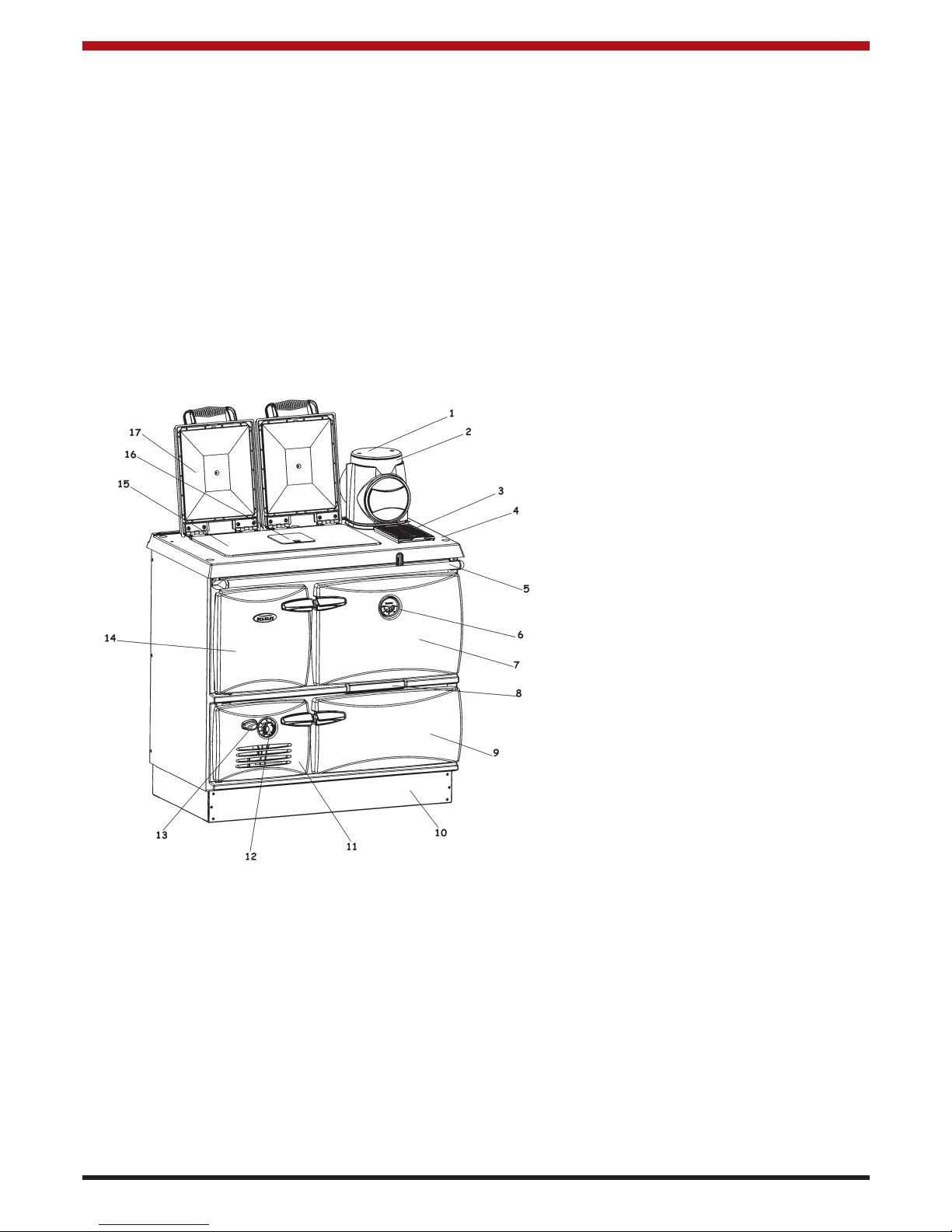
1. Blanking Plate
2. 6” Flue Box
3. Trivet
4. Hob
5. Towel Rail
6. Oven Thermometer
7. Main Oven Door
8. Front Cleaning Door
9. Warming Oven Door
10. Base Frame
11. Ashpit Door
12. Boiler Thermostat
13. Riddling Cover
14. Fire Door
15. Hotplate
16. Cleaning Panel to Hotplate
17. Hotplate Covers
SCHEMATIC
CONTROL OF SUBSTANCES
This cooker may contain some of the materials
indicated below. It is the users/installers
responsibility to ensure his/her personal protection
when handling the pertinent items:- fire cement, fuel
beds, artificial fuels. When handling use disposable
gloves. Glues and sealants - exercise caution. If
they are liquid use face mask and disposable
gloves. Glass yarn or rope, mineral wool, rock wool,
insulation pads, ceramic fibre, coal dust may be
harmful if inhaled. They may also irritate the skin,
eyes, nose and throat. Use disposable gloves, face
mask and eye protection. Wash other exposed
parts after handling. When disposing of the rubbish
reduce dust with water and wrap them securely.
Page 4
4
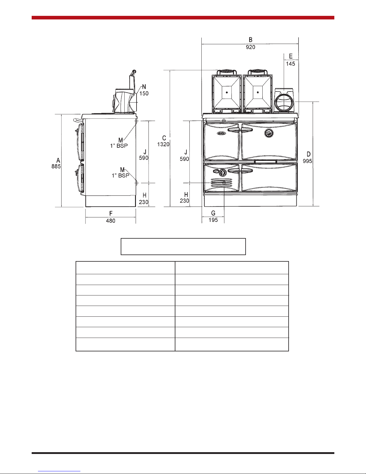
SPECIFICATION
TECHNICAL DATA
COOKER OUTPUT: AT
GROSS OUTPUT per hour 35 kW = 120,000 BTU’s
NET TO WATER per hour 17.6 kW = 60,000 BTU’s
RADIATION SURFACE: Heating surface only = 32.7 sq. Meters = 353 sq. ft.
Heating plus Domestic Hot Water = 30.2 sq. Meters sq. ft.
COOKER WEIGHT: Net: 360Kgs Gross: 400Kgs
FEATURE METRIC
HOT PLATE 560 x 330
ROASTING OVEN 390W x 310H x 406D
SIMMERING OVEN 390W x 220H x 406D
FIREBOX 220W x 500H x 400D
ASHBOX 220W x 200H x 400D
FUEL CAPACITY .02 Cu. METERS
LOG SIZE 380 LONG
Note: Dimensions stated above may be
subject to a slight +/- variation
Page 5

5
INSTALLATION
Installation must comply with the following:
B.S. 8303 - Code of Practice for the installation of
domestic heating and cooking appliances burning
solid mineral fuels.
Building Regulations - Part J.
Local Authority by-laws and other specifications as
they affect the installation of the cooker.
PRE-INSTALLATION CHECK - LOCATION
When choosing a location for this appliance you
must have:
(a) Sufficient room for the installation (see
clearances), a satisfactory flue (see chimneys),
and an adequate air supply for correct
combustion and operation.
(b) Adequate space for maintenance and air
circulation.
(c) Check that the chimney is clean and clear of
obstructions. Cracked brickwork and leaking
joints should be made good.
HEARTH CONSTRUCTION
Hearth should be strong enough to support total
weight of cooker. When a properly constructed
hearth is not available we recommend that the
Cooker be placed on a slab of foamed concrete 7.5
cm (3”) or a slab of other insulating material. This
hearth must extend at least 45 cm (18”) to the front
and 30 cm (12”) to each side.
CHIMNEY/FLUES
The chimney should have a cross sectional area of
at least 176 sq. cm (28 sq. ins) or an inner diameter
of 150mm to 230mm. (6” to 10”). (See fig. 1 & 2).
Do not connect to a chimney serving another
appliance. Always ensure that the connection is to a
chimney of the same size, never connect to one of
smaller dimensions. Chimneys wholly constructed of
single skin are not recommended under any
circumstances. Due to their inability to retain heat,
such chimneys will inevitably give rise to smoking,
down draught and the formation of condensation.
The flue must be high enough (more than 4.6m
(15ft.) in any case) to allow the flue gasses to vent
into clear air, away from the turbulence that may be
caused by roof structures, other chimney stacks etc.
The venting position should be 1.0m (3’3”) above
any obstruction within a 7.6m (24’9”) radius, if down
draughts are to be avoided.
Fig.2
Fig.1
Page 6
6
Where the standard masonry chimney is not
available, a proprietary type of twin wall, fully
insulated pipe may be used. As already stated, the
minimum inner diameter must not be less than 15
c.m. (6”) and the pipe must terminate at a point not
lower than the main ridge or adjacent outside
obstructions. With such installations access to the
chimney must be provided for cleaning purposes.
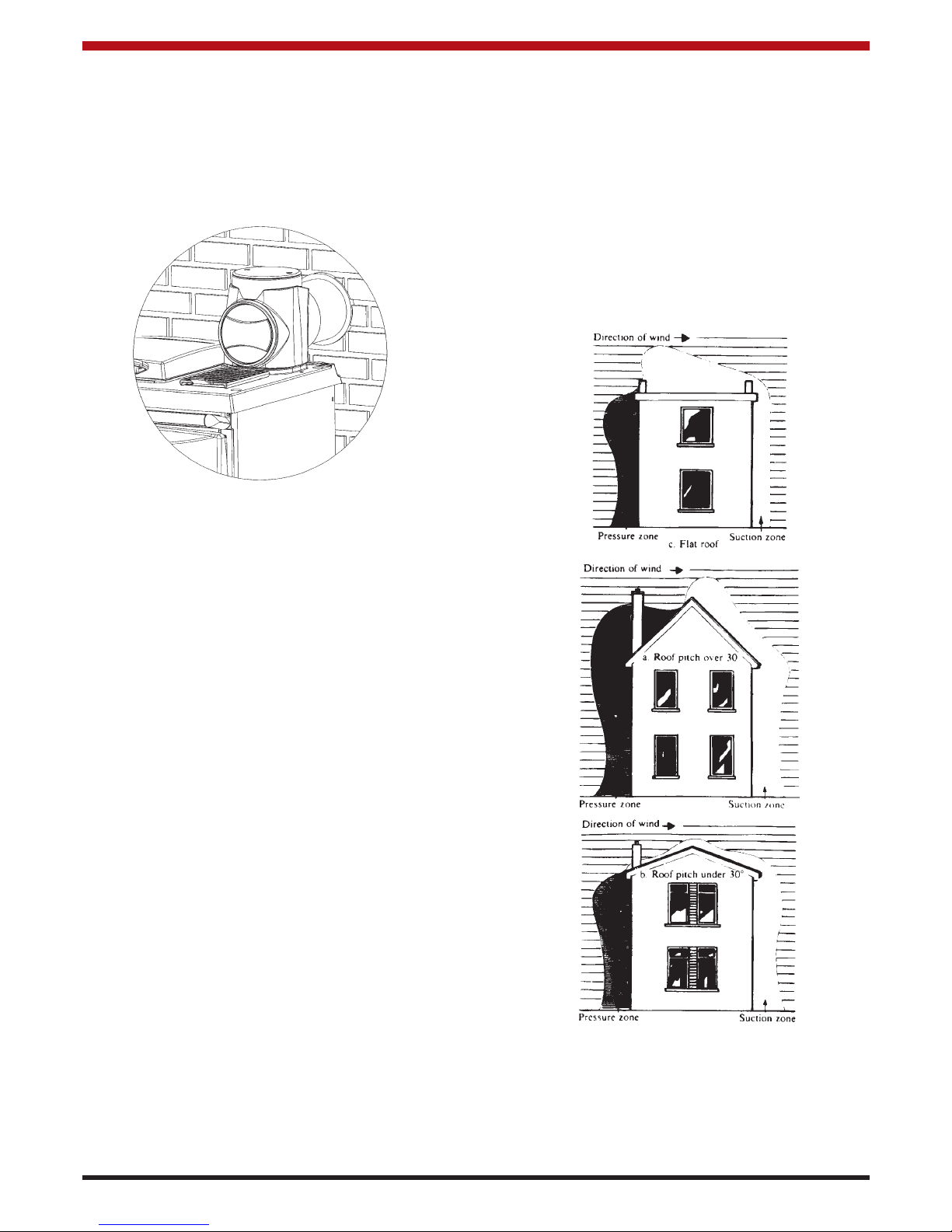
FLUE BOX
Apply fire cement to the socket in the hob. Attach a
short length of 6” (150mm) I.D. pipe approx. 10”
(250mm) long to the outlet of the flue box by means
of fire cement. Place the flue box on the hob and the
pipe into the wall and consolidate the fluebox and
pipe into the fire cement. Apply 3 or 4 coils of 10mm
(
1
/2
’) insulating rope to the pipe and fill the wall cavity
with fire cement. (See fig. 3).
FLUE PIPES/CONNECTIONS
Square bends and long horizontal runs of flue piping
must be avoided. There is provision with the Cooker
for two methods of installation i.e. top outlet or back
outlet.
ALL FLUE CONNECTIONS MUST BE
THOROUGHLY SEALED. Blocked chimneys are
dangerous, use only recommended fuels, keep
chimneys and flue ways clear; read the operating
instructions.
STANLEY CAST IRON PIPES ARE HIGHLY
RECOMMENDED FOR INTERIOR USE.
DRAUGHT REQUIREMENTS
When a draught recorded is over .10 inches W.G. a
draught stabiliser should be fitted. Remember a
proper flue is necessary for the efficient operation of
the Cooker. The chimney should be capable of
providing a continuous negative pressure of
between .06 and .10 inches WG.
Excessive draught can be controlled by rotating the
spin valve on the flue box in an anticlockwise
direction.
DOWN DRAUGHTS
However well designed, constructed and positioned,
the satisfactory performance of the flue can be
adversely affected by down draughts caused by
nearby hills, adjacent tall buildings or trees. These
can deflect wind to blow directly down the flue to
create a zone of high pressure over the terminal.
A suitable anti-down draught terminal or cowl will
usually effectively combat direct down draught but
no cowl is likely to prevent down draught due to a
high pressure zone. (See fig. 4).
COOKER CLEARANCE
The Cooker should not be installed at zero
clearance to combustible materials. The sides
should have a minimum clearance of at least 7.5 cm
(3”) from combustible materials unless otherwise
fully insulated.
Fig.3
Fig. 4
Page 7

7
PLUMBING
PIPE FUNCTION PIPE FUNCTION
RADIATOR FIRST
HEATING FLOOR 1 PUMPED FLOW TO RADIATORS 7 HOT WATER FLOW
CIRCUITS 2 PUMPED RETURN EX 8 COLD WATER (EX TANK)
3 PUMPED FLOW TO RADIATORS 9 COLD FEED-HEAT SYSTEM
GROUND 4 PUMPED RETURN EX 10 OPEN VENT-HEAT SYSTEM
CYLINDER FLOOR 5 GRAVITY FLOW TO CYLINDER 11 COLD FEED TO CYLINDER
HEATING 6 GRAVITY RETURN EX 12 HOT WATER VENT
CIRCUIT FIRST 13 MAINS WATER
FLOOR T THERMOSTAT
ISOLATING VALVES
This diagram
illustrates the basic
principals of water
systems and is not to
be regarded as a
working drawing.
Recommended indirect cylinder 135-180 litres, depending on domestic requirements with a 2.5 cm (1”) flow and return
pipes not exceeding 7.8m (25’6”) each in length. Cylinder and pipework should be lagged to minimise heat losses.
REGULATIONS
The plumbing must be in accordance with all
relevant regulations and practices. It must include a
gravity circuit with expansion pipe, open to the
atmosphere. The central heating will normally be
pump-driven as with other types of boilers. In
indirect domestic water closed circuit central heating
the system is thermostatically controlled by the unit
mounted in the ashpit door.
BOILER OUTPUT
High output cannot be maintained unless fuel is
being burned at a rate of 4.6 Kg. per hour of coal.
When burning peat or wood, reduced output will
apply because of the lower calorific value of the
fuels.
GRAVITY CIRCUIT
The gravity circuit consists of the domestic hot water
tank of 135 - 180 litres indirect cylinder, fixed in an
upright position, recommended for hot water storage
and it should be connected to the boiler by 25mm
(1”) ID flow and return piping. The pipes should not
exceed 7.8m (25’6”) each in length and anything in
excess of 4.6m (15ft.) must be fully lagged. The
shorter the run of pipe work the more effective the
water heating efficiency and to this end, the cylinder
should be fully lagged. For safety’s sake do not
have any valves on this circuit.
Fig. 5
Page 8

8
EXPLODED VIEW
1. Front
2. Hob
3. Trivet
4. Riddling Handle
5. Side Panel RH
6. Back Panel
7. Side Panel Clamping
Bracket
8. Boiler Blanking Plate Upper
9. Short Thermostat Strip
10. Long Thermostat Strip
11. Donard SF Ashpan
12. Base
13. Lower Blanking Plate
14. Enamelled Front Cleaning
Door
15. Damper Assembly
16. Hotplate Cover
17. Boiler Assembly
18. Bonnet
19. Fire Door Assembly
20. Oven Door Assembly
21. Warming Door Assembly
22. Ash Door Assembly
23. RH Towel Rail Bracket
24. LH Towel Rail Bracket
25. Serial Number Plate
26. Steam Escape
27. Hotplate
28. Cleaning Plate To Hot Plate
29. Flue Top Back Guide
30. Flue Top Front Guide
31. One Piece Oven Base
32. Oven Bottom Back
33. Oven Bottom LH
34. Oven Bottom RH
35. Oven Bottom
36. Top Oven Top
37. Flue Way Right
38. Right Side Oven Top
39. Left Top Oven Side
40. Oven Top
41. Cleaning Plate To Hob
42. Cleaning Brush
43. Poker
44. Scraper
45. Roasting Tin
46. Oven Shelf
47. Stay Rod
48. Roasting Tin Grid
49. Ashpan Lifter
50. Towel Rail
51. Catch
52. Steam Vent
53. Stay Rod Nut
54. Stay Rod Nut Cup
55. Front Cleaning Door
Gasket
56. Front Door Cleaning Clip
57. RH Door Handle Assy
58. Thermometer
59. Warming Oven Door Panel
60. Main Oven Door Panel
61. Door Hinge
62. Thermostat
63. Protection Mesh
64. Extended Door Hinge
65. Ash Door Back
66. Spacer
67. Port Hole Cover
68. Thermostat Knob
69. Base Plate
70. LH Door Handle Assembly
71. Badge
72. Warning Label
73. Fire Door Back
74. Fix Plate LH
75. Fix Spindle
76. Fire Bar Link
77. Grate
78. Fire Bar
79. Baffle
80. Summer Side Brick
81. Riddling Grate
82. Summer Back Brick
83. Secondary Air Pipe
84. Summer Front Brick
85. Summer Grate Support
86. Oven Damper Knob
87. Damper Axle
88. 3” Butt Hinge
89. Hotplate Cover Panel
90. Spring Handle
91. Hotplate Cover Bracket LH
92. Hotplate Cover Bracket RH
93. Hotplate Cover Filler Plate
94. Hotplate Cover Stop
95. Bonnet Spin Valve
96. Bonnet Body
97. Bonnet Cleaning Door
98. Boiler Plug
99. Spin Valve
100.Hinge Sleeve
101.RH Fixing Plate
Page 9

9
INJECTOR TEE
Where the gravity and central heating circuits join
together to return to the Cooker we recommend the
use of an injector tee connection, situated as close
to the unit as possible. This type of tee encourages
a stable flow of hot water through both circuits and
helps to prevent priority being given to the stronger
flow, which is most commonly the pumped central
heating circuit. (See fig. 6).
WATER CIRCUIT TEMPERATURE
The return water temperature should be maintained
at not less than 40
o
C so as to avoid condensation on
the boiler and return piping. Fitting a pipe thermostat
to the return from the gravity circuit and wiring it into
the pump control will ensure that no cold water will
be returned from the central heating circuit before
the water from the gravity circuit has warmed up to
the common return pipe and boiler. If this is not
sufficient to keep the boiler temperatures above the
required minimum, a three-way mixing valve may be
fitted to the flow pipe to divert some hot water
straight back into the return. Such a valve can be
operated either manually or electrically in
conjunction with a return pipe thermostat.
PIPE THERMOSTAT
Another advantage of fitting a pipe thermostat on the
gravity return is that priority will always be given to
the domestic hot water supply.
FUELS
The Cooker output levels are assessed on standard
House Coal of good quality. Reduced outputs will
result when fuels of lower calorific values are used.
Wood logs up to 38cm (15”) long are suitable.
All fuels should be stored under cover and kept as
dry as possible prior to use.
SECONDARY AIR PIPE
The Secondary Air Pipe is for use with House Coal,
Timber and Peat Fires only. It must be removed
when burning Anthracite or other smokeless fuels.
CIRCULATING PUMP
It is recommended that the selected pump be of a
proprietary type and manufacture, and be adequate
to give the required temperature differential between
the flow and return. The pump should be able to
meet the requirements of the system design and be
fitted in a readily accessible position. It may be
positioned either on the boiler section flow or the
return, depending on the system design.
Isolating valves (preferably of the keyless type) must
be fitted to the inlet and outlet of the circulating
pump to facilitate service and replacement of pump
without draining the system.
Pipework not forming part of the useful heating
surface should be insulated to help prevent heat
loss and possible freezing, particularly where pipes
are run through roof spaces and ventilated
underfloor spaces. Cisterns situated in areas which
may be exposed to freezing conditions should also
be insulated.
Draining taps must be located in accessible
positions which permit the draining of the whole
system, including the appliance and hot water
storage vessel. Draining taps should be at least
1
/2in. (12.5mm) BSP nominal size and be in
accordance with BS 2879.
The appliance boiler section should be connected to
a cistern water supply, subject to a maximum head
of 18.25m (60ft).
The heating system must be designed (and adjusted
if necessary) to give a temperature differential
across the boiler at full output of 10
o
- 14oC (18o35oF). The use of horizontal pipe runs should be
avoided wherever possible in order to prevent the
collection of air in the system. If horizontal runs are
unavoidable the pipes should rise upwards in the
direction away from the appliance.
FUEL CALORIFIC VALUE
Anthracite 25 - 50mm Calorific Value 8.2 kW/KG = 14,000 BTUS/LB
House Coal 25 - 75mm Calorific Value 7.2 kW/KG = 12,300 BTUS/LB
Timber - Firebox Size Calorific Value 5.0 kW/KG = 8,600 BTUS/LB
Peat Briquettes - Calorific Value 4.8 kW/KG = 8,300 BTUS/LB
Bog Peat - Calorific Value 3.4 kW/KG = 6,000 BTUS/LB
Fig. 6
INHIBITORS
We strongly recommend the use of corrosion
inhibitors and anti-freeze solution in the system.
Use only quantities specified by the inhibitor
manufacturer. Add inhibitor only after flushing
when finally re-filling the system. Refer to BS 7953.
Injector Tee Samples
Typical Logs
Page 10

10
LIGHTING THE FIRE
Thoroughly check all pipe work for leaks, especially
the pipe connections to the boiler before lighting.
Allow the Cooker to build up heat slowly at first.
Check that all dampers and catches are operating
correctly and ensure that all flue connections are
thoroughly sealed. See that the user has a copy of
the operating instructions.
Fully open the thermostat and direct damper and
kindle with paper and sticks in the usual way and
ignite by using a taper or rolled wad of paper
inserted into the ashpit. Under no circumstances
should any inflammable liquid i.e. petrol, paraffin etc.
be used to light the fire. When the fire is well
established close the direct damper fully and keep it
closed. Add fuel to the firebox as required and adjust
the thermostat to suit the current requirements.
FUELLING
When fuelling open the direct damper as this will
help to eliminate smoking. Afterwards be sure to
close the output from the boiler. Never pack fuel
tightly or fill the firebox to capacity. A lower level fire
is more effective particularly in regard to water
heating efficiency. The maximum fuel level is up to
the bottom of the firebox door and rising upwards at
a 30oangle towards the back of the firebox.
CONDENSATION
If the appliance is run for extended periods on a low
fire, especially when burning wood or peat the fire
can cool down to such an extent that vapour in the
flue gases may condense. This will make the inside
of the flue damp so that the soot sticks to the flue
and the tarry mixture formed may drip down into the
appliance. It is always a good idea to run at a high
rate whenever possible, because it is so easy to
light, a lot of people, especially in the Summer, run
the appliance for just a few hours with a strong
roaring fire. The appliance is then allowed to die
until the hot water is used up and then is relit. From
the appliance and flue point of view, this is a better
technique than running a low fire continually. (Fig. 7)
EXTERNAL RIDDLING
Lift the port hole cover on the ash door and insert the
operating tool into the hole until it engages with the
spigot on the grate and move vigorously. In addition
it is also recommended that the firebed itself be
thoroughly raked at intervals thus loosening up such
debris as clinker, stones, etc. which are then easily
removed. (Fig. 8).
OPERATION
Fig.8
Fig.7
Fig.7a
Page 11

11
ASH REMOVAL
Some attention should be paid to the amount of ash
that is allowed to build up in the firebox. Wood has
better burning characteristics if a bed of ash is
allowed to build up, riddling only being necessary to
level up the fire (for cooking, for example). Coal or
smokeless fuels, on the other hand, burn better if
they are well riddled to allow a good airflow to the
fire. For slow combustion it is better to have a
thicker ash bed for all fuels. Therefore, do not riddle
the fire before slowing it down for overnight burning,
but riddle it if required in the morning or before
cooking.
When using anthracite or coal avoid excessive firing
conditions. High temperatures are unnecessary and
can do serious harm to the cooker. The first
indication that overheating is taking place will be the
formation of clinker (melted ash) in the firebox and
this should be removed immediately otherwise
damage will occur to the firebars and cooker
components and any damage here should be
repaired without delay.
ASHPAN
The ashpan must be emptied as required otherwise
ash will build up to a point where it interferes with the
natural flow of cool air through firebars and as a
consequence these will be damaged.
THERMOSTAT WITH MANUAL OVERRIDE
The air supply to the fire is controlled by the
thermostat probe inserted into the boiler and the
control knob attached to the ash door.
The automatic thermostat has 6 settings which
control the heat to which the boiler water will rise for
central heating purposes. Setting 0 will close the
thermostat, setting 3 will give a nominal burning rate
of 2
1
/2 to 3kg per hour of house coal. Setting 5 will
give maximum water heating and high oven
temperatures.
The thermostat will close down when the water heat
reaches the temperature chosen by the selected
setting, it will close fully when the water temperature
reaches 90 - 95oC when set at 5 - to prevent boiling.
(See Fig. 9 & 10)
The thermostat manual override has 4 settings
which retain the air flap in a predetermined open
position for steady heat when baking and cooking. It
will only close fully when the water temperature
reaches 90 - 95
o
C when set at 5 - to prevent boiling.
OVERNIGHT BURNING
There is a small air bypass into the ashdoor and this
is normally sufficient when the thermostat is closed
to hold the fire at least 10 hours after banking. If the
fire is out and the fuel unburned set the control knob
of the thermostat from
1
/2 to 1 in order to sustain
overnight burning.
FIREDOOR SPIN VALVE
Fig.9
Fig.10
Fig.11
Page 12

12
ASHDOOR SPIN VALVE
The ashdoor spin valve allows additional air to the
firebox for marginal draught conditions. This can be
adjusted to suit your requirements. Close when
setting the cooker for overnight burning. (See fig.12)
BOILER INSULATING PLATE
This plate is fitted by removing the hotplate and
sliding the insulating plate down between the boiler
and oven side. Make sure that the spacing
projections are facing the oven and the top flange is
resting on the boiler. Replace the hotplate.
The boiler insulating plate may be used with the
summer plates or on its own as a means of reducing
the boiler output and increasing the heat to the oven.
(See fig. 13)
SUMMER GRATE & HEAT SHIELD ASSEMBLY
INSTALLATION INSTRUCTIONS
To obtain a reduction in boiler output during the
summer the Cooker is supplied with a removable
summer grate and cast iron heat shield plates as
standard. Remove the existing rocker grate and
stand the summer grate on the supporting legs after
inserting it through the firedoor. Fit heat shield plates
as shown in diagram. (See fig. 14 & 15)
Fig.12
Fig.13
CONTENTS QTY
1. Support legs (2)
2. Summer Grate (1)
3. Back Heat Shield Plate (1)
4. Side Heat Shield Plate (2)
5. Front Heat Shield Plate (1)
ASSEMBLY
1. Remove the rocker grate through the ashpit
door. Brush down the sides of the fire
chamber and clean out the debris before fitting
the summer grate and heat shields.
Fig.14
Fig.15
Heated secondary air enters the firebox through a
spin valve in the firedoor back plate while the valve
is open to assist combustion of smoke volatiles.
Close when burning anthracite. (See Fig. 11)
Page 13

13
INTERNAL/FLUE CLEANING
The flue or chimney will need to be cleaned
regularly. How often will depend a lot on how your
Cooker is run, but, to start with, make a point of
inspecting the flue system every one or two weeks.
This period may well be extended as time goes by if
there is little sign of deposits. Some people find
they need to sweep the flue every six to eight weeks
but a longer period is more normal and in some
cases this may be as long as 12 months.
For most efficient heat transfer to water jacket, all
surfaces that come into contact with the flue gases
should be kept clean. Regular cleaning will
maintain the efficiency of the unit. Use the scraping
tool to remove deposits from the inside surfaces of
the firebox, the flue ways and top water tube.
Regularly look at the top and side of the oven by
removing the hotplate cleaning panel and removing
the deposits with scraper. To help keep deposits to
a minimum, it is a good idea to have a fast fire for 15
minutes at least once a week. Loose deposits will
be scoured off and will make the necessity of
cleaning out less frequent.
Fig.17
Fig.18
The insulating covers retain most of the heat that
would otherwise be radiated into the kitchen. They
also retain the heat in the hotplates so that rapid
heating of cooking utensils will result when one or
both of them are lifted for cooking purposes. (See
Fig. 16)
COOKING UTENSILS
For best cooking results use heavy based, flat
bottomed utensils.
USE OF OVENS
When baking or roasting, close the direct damper
and open the thermostat fully until the thermometer
shows a temperature about 50
o
F higher than that
which is required. Then close the thermostat to a
point where the required temperature is sustained
(a little practice will soon show how much thermostat
adjustment is necessary). Much will depend on the
strength of the chimney draught. It will be found that
a thermostat setting of 3 will be suitable in most
cases.
The main oven is heated on all four faces. The
simmering oven is heated on the top face only.
The temperature will be about half that of the main
oven, for slow cooking, of casseroles, stews, soups
etc.
HOTPLATE INSULATING COVERS
Fig.16
2. Insert the support legs (item 1) through the
fire door and rest them on the shaker grate
support lugs. To lock support legs into
position, fit legs as per fig. 15.
3. Insert the summer grate (item 2) through the
fire door and rest it on the support legs
(item 1).
4. Insert the heat shield plates in the following
order - items 3, 4 and 5.
NB. When using the summer grate and heat
shields it will be necessary to use a poker to
clear ash before refuelling.
Every week, depending on the type of fuel used, it
will be necessary to take off the cleaning access
plates to remove deposits. Some people use a
vacuum cleaner to remove these deposits. The
procedure is as follows: Allow cooker to cool down
Page 14

14
CLEANING
IMPORTANT: BE CAREFUL OF THE HOT
APPLIANCE.
General cleaning must be carried out when the
cooker is cool.
Stanley cookers are finished in a high gloss vitreous
enamel. To keep the enamel in the best condition
observe the following tips:
1. Wipe over daily with a soapy damp cloth,
followed by a polish with a clean dry duster.
2. If milk, fruit juice or anything containing acid is
spilt on the hob or down the cooker, be sure to
wipe it immediately or the vitreous enamel may
be permanently discoloured. Jam and
preservatives containing sugar can permanently
damage the vitreous enamel.
3. Keep a damp cloth to hand while cooking, to
wipe up any spills as they occur, so they do not
harden and become more difficult to remove
later.
4. If spills do become baked on, a cream cleanser
can be used. For stubborn deposits a soap
impregnated pad can be carefully used on the
vitreous enamel.
5. Use only products recommended by the
Vitreous Enamel Association, these products
carry the Vitramel label.
6. In the oven, spills and fat splashes are
carbonised at high temperatures: occasionally
brush out with a stiff brush. The shelves can be
soaked and cleaned with a cream cleanser.
7. Both insulating covers should be raised and
allowed to cool before cleaning the enamel with
a soapy damp cloth. Use a wire brush to keep
the cast iron hotplate clean.
DO NOT USE ABRASIVE PADS OR OVEN
CLEANERS CONTAINING CITRIC ACID ON
ENAMELLED SURFACES. ENSURE THAT
THE CLEANSER MANUFACTURERS
INSTRUCTIONS ARE ADHERED TO.
Association
completely, remove all loose sections on top of the
Cooker, open the direct damper, remove the flue box
plate from the flue chamber and remove the
cleaning door from the front of the Cooker in order to
obtain access. Remove the hotplate cleaning panel
and hob cleaning plate, and clean the heat collecting
fins on the hotplate. Carbon deposits on these
surfaces will reduce efficiency by up to 20%. All
deposits from the flue pipe and the top of the oven
may be brushed both into the firebox and down the
side of the oven.
Deposits which have accumulated on the side of the
oven must also be brushed downwards. To remove
the accumulated ash and soot, thoroughly clean out
the residue from the side flues and base plate
through the front cleaning door opening — this
operation is essential otherwise the flow of hot
gases will be obstructed and satisfactory oven
temperatures will not be maintained, apart from
which such deposits may contribute to smoking.
Replace all the loose parts which have been
removed making sure that all cooking surfaces have
been thoroughly cleaned on the underside. (See
Figs. 17, 18 & 19).
GRATE REMOVAL
Lift the back of the grate and push it in towards the
back of the boiler until the front of the bars pass the
front casting. Tilt the grate up on the right hand side,
drop down the left hand side towards the back of the
boiler and pass the grate through the opening in the
front casting, taking care not to damage the enamel.
Fig.19
Page 15

OPENING COOKER DOOR
Fig.20
Fig.21
1. To Open Door Lift handle and pull door open. See
Fig. 20.
2. To Close Door - Lift handle, push door closed,
press down to engage latch and release. See
Fig.21.
15
Page 16

16
FAULT FINDINGS
1. Poor Chimney Draught (a) Obstruction (a) Clear and Clean
(b) Too Low (b) Raise Height above Ridge
(c) Too Wide (c) Fit Flue Liner 15 to 23 c.m.
(d) Crack in Wall (d) Repair Cracks
(e) Shared by another unit (e) Cut of other Unit.
2. Excessive Chimney Draught (a) High Chimney (a) Open Flue Cover of fit Draught Stabiliser
3. Down Draught (a) High Trees (a) Raise Chimney Height
(b) High Buildings (b) Raise Chimney Height
(c) Negative Pressure Zone (c) Fit Cowl
4. Cooker Smoking (a) Insufficient Primary Air (a) Provide Room Air Inlet
(b) Chimney Choked (b) Clean Chimney
(c) Side Flueways Choked (c) Clean Flueways
(d) Down Draught (d) Raise Chimney Height
5. Hot Plate Not Heating (a) Soot Under Hot Plate (a) Remove and Clean
(b) Fire too Low (b) Build better Fire
(c) Utensils not Flat (c) Use machined based Utensils
6. Oven Not Heating (a) Poor Chimney Draught (a) Raise Height or Fit Cowl
(b) Flueways blocked with soot (b) Clean Out
(c) Damper open to Chimney (c) Close Damper
(d) Faulty Thermostat (d) Check and replace if necessary
7. Radiators Not Heating (a) Pump not Working (a) Check and replace if defective
(b) Air in Radiators (b) Vent Radiators
(c) Pipe System Faulty (c) Check Pipe Sizes and Circuit
(d) Excessive Number of Radiators (d) Turn off un-needed Radiators
(e) Radiator Valves not adjusted (e) Adjust Valves to give even flow
8. Domestic Hot Water Cylinder (a) Cylinder too Large (a) Use 135 - 180 L Cylinder
not heating (b) Flow Pipe too small (b) Use 25mm Bore Pipe
(c) Flow Pipe crossed (c) Reverse Flow Pipe
(d) Cylinder too far away (d) Not more than 7.8m fully lagged.
(e) Hot water from boiler not (e) Adjust Flow Control Valves or
reaching cylinder fit injector tee.
9. Intermittent Performance (a) Cooker starved of Primary Air (a) Provided Air Inlet in Room.
(b) Extraction Fan in room (b) Provide additional Air Inlet in room
(c) Cooker subjected to wind (c) Raise Chimney of Fit Cowl
change
(d) Dirty Flueways (d) Clean Flueways Frequently.
(e) Poor Fire (e) Burn more Fuel
(f) Uncontrolled Burning (f) Repair or Replace Thermostat
10. Domestic Hot Water Rusty (a) Leak in Indirect Cylinder Coil (a) Replace Cylinder
(b) Incorrect Cylinder Fitted (b) Check with installer
It is of the utmost importance to keep the flue pipe and chimney clear of deposits by regular sweeping of the
chimney irrespective of whether the fuel used is classed as smokeless or not. All fuels give rise to soot or ash
deposits and regular cleaning is essential for safe operation.
Blocked or partially obstructed flueways and chimneys will cause dangerous fumes to be emitted into the room,
these may well be invisible if a smokeless fuel is burned.
Page 17

INSTALLATION CHECK LIST
Flue System
1. Minimum Flue Height of 4.6 metros (15 feet).
2. Appliance should be connected to a minimum of 1.8 metres (6 feet) of 150mm (6”)
flue pipe with a horizontal run not exceeding 300mm (12”).
3. Appliance should be connected to a chimney of less than 250mm (10”) in diameter
(otherwise the chimney must be lined with a 6” flue liner).
4. The chimney venting position must be above the main ridge of the roof or adjacent
outside obstructions.
5. The chimney serving this appliance should not serve any other appliance.
Location
6. Clearance to combustible materials must be maintained as specified in the
Clearance to Combustibles section.
7. If the cooker is located on a combustible surface, a floor protector must be used to
cover the area underneath the heater, extending 18” from the front of the cooker
and 8” from the back & sides.
Plumbing
8. Appliance must be connected to a gravity circuit using 1” ID flow & return piping.
9. The length of pipes from the cylinder to the cooker should not exceed 7.8 metres
(25
1
/2 feet).
10. A circulation pump should be fitted to the return pipe and controlled by a pipe stat
fitted to the flow pipe of the gravity circuit to the cylinder.
Ventilation & Combustion Air Requirements
11. The room in which the appliance is located should have an air vent of adequate
size to support correct combustion (see Ventilation & Combustion Air Requirement
Section).
Tick
√
17
Page 18

Rev: 003 DP 090320
N00441AXX
Manufactured by
Waterford Stanley Ltd.,
Unit 210, IDA Industrial Estate, Cork Road,
Waterford, Ireland.
Tel: (051) 302300 Fax (051) 302315
Website: www.waterfordstanley.com
18
WARRANTY
CONDITIONS OF WARRANTY
Your Stanley cooker is guaranteed against any part that fails (under normal operating conditions) from the
date of installation of the appliance. If the unit is not installed within six months of date of purchase, the
warranty will commence six months from the date of purchase. The warranty is given only to the original
consumer/purchaser only and is non-transferable. The appliance must be installed by a suitable qualified
person and installed as per the requirements of this manual. Failure to comply with the installation
requirements will void your warranty. Waterford Stanley reserve the right to replace any part due to
manufacturing defect that fails within the warranty period under the terms of the warranty. All Oil & Gas
appliances must be commissioned by an authorised Stanley Engineer to validate your warranty. The unit must
be used for normal domestic purposes only and in accordance with manufacturer's operation instructions.
LIMITS OF LIABILITY
The warranty does not cover:
* Special, incidental or consequential damages, injury to persons or Property, or any other consequential
loss.
* Any issue with caused by negligence, misuse, abuse or circumstances beyond Waterford Stanley’s
control.
* Any issue with wear and tear, modification, alteration, or servicing by anyone other than an authorised
service engineer.
* Installation and operational related problems such as draught related issues external to the cooker,
inadequate venting or ventilation, excessive flue offsets, negative air pressure caused by insufficient
burning of improper fuel.
* Damage caused to the unit while in transit.
* Enamel discolouration due to over firing, enamel damage caused by impact, damage to baffles caused
by over firing and fading of surface finish on casting.
* Stress fractures on bricks.
* Rust on cast iron parts unless reported prior to unit being installed.
Note: Adequate clearance must be maintained around the appliance to ensure the ease of part removal in
the possible event of their damage/failure. Waterford Stanley are not responsible for any costs
incurred in the removal of items installed in the vicinity of the appliance that have to be moved to
facilitate a part replacement.
All warranty claims must be reported to the Waterford Stanley Service Department and must be submitted
with the product serial number (located on the front casting), date of purchase, proof of purchase (if
requested) and details of the specific nature of the problem.
 Loading...