

Page 1
ERRIGAL OIL FIRED COOKER
DRY, DHW & HPB MODELS
INSTALLATION & OPERATING INSTRUCTIONS
Page 2

1
TABLE OF CONTENTS
PAGE NO.
1. Introduction . . . . . . . . . . . . . . . . . . . . . . . . . . . . . . . . . . . . . . . . . . . . . . . . . . . . . . . . . . . . . . . . . 2
2. Specification . . . . . . . . . . . . . . . . . . . . . . . . . . . . . . . . . . . . . . . . . . . . . . . . . . . . . . . . . . . . . . . . . 3
3. Technical Data . . . . . . . . . . . . . . . . . . . . . . . . . . . . . . . . . . . . . . . . . . . . . . . . . . . . . . . . . . . . . . . 3
4. Installation. . . . . . . . . . . . . . . . . . . . . . . . . . . . . . . . . . . . . . . . . . . . . . . . . . . . . . . . . . . . . . . . . . . 4
5. Location . . . . . . . . . . . . . . . . . . . . . . . . . . . . . . . . . . . . . . . . . . . . . . . . . . . . . . . . . . . . . . . . . . . . 5
6. Hearth Construction . . . . . . . . . . . . . . . . . . . . . . . . . . . . . . . . . . . . . . . . . . . . . . . . . . . . . . . . . . . 5
7. Fuel Supply / Installation. . . . . . . . . . . . . . . . . . . . . . . . . . . . . . . . . . . . . . . . . . . . . . . . . . . . . . . . 5
8. Oil Storage Tanks . . . . . . . . . . . . . . . . . . . . . . . . . . . . . . . . . . . . . . . . . . . . . . . . . . . . . . . . . . . . . 5
9. Fuels . . . . . . . . . . . . . . . . . . . . . . . . . . . . . . . . . . . . . . . . . . . . . . . . . . . . . . . . . . . . . . . . . . . . . . 5
10. Fuel Supply Line . . . . . . . . . . . . . . . . . . . . . . . . . . . . . . . . . . . . . . . . . . . . . . . . . . . . . . . . . . . . . . 5
11. Clearance to Combustibles. . . . . . . . . . . . . . . . . . . . . . . . . . . . . . . . . . . . . . . . . . . . . . . . . . . . . . 6
12 Flue System . . . . . . . . . . . . . . . . . . . . . . . . . . . . . . . . . . . . . . . . . . . . . . . . . . . . . . . . . . . . . . . . . 7
13. Flue Height . . . . . . . . . . . . . . . . . . . . . . . . . . . . . . . . . . . . . . . . . . . . . . . . . . . . . . . . . . . . . . . . . . 7
14. Flue Cleaning . . . . . . . . . . . . . . . . . . . . . . . . . . . . . . . . . . . . . . . . . . . . . . . . . . . . . . . . . . . . . . . . 7
15. Use of Existing Flues and Chimneys . . . . . . . . . . . . . . . . . . . . . . . . . . . . . . . . . . . . . . . . . . . . . . 7
16. Flue Liners . . . . . . . . . . . . . . . . . . . . . . . . . . . . . . . . . . . . . . . . . . . . . . . . . . . . . . . . . . . . . . . . . . 8
17. Sealing . . . . . . . . . . . . . . . . . . . . . . . . . . . . . . . . . . . . . . . . . . . . . . . . . . . . . . . . . . . . . . . . . . . . . 8
18. Connections . . . . . . . . . . . . . . . . . . . . . . . . . . . . . . . . . . . . . . . . . . . . . . . . . . . . . . . . . . . . . . . . . 8
19. Ventilation & Combustion Air Requirements. . . . . . . . . . . . . . . . . . . . . . . . . . . . . . . . . . . . . . . . . 8
20. Draught Requirements . . . . . . . . . . . . . . . . . . . . . . . . . . . . . . . . . . . . . . . . . . . . . . . . . . . . . . . . . 8
21. Down Draughts . . . . . . . . . . . . . . . . . . . . . . . . . . . . . . . . . . . . . . . . . . . . . . . . . . . . . . . . . . . . . . . 9
22. Factory Made Insulated Chimneys . . . . . . . . . . . . . . . . . . . . . . . . . . . . . . . . . . . . . . . . . . . . . . . . 9
23. Suitable Materials . . . . . . . . . . . . . . . . . . . . . . . . . . . . . . . . . . . . . . . . . . . . . . . . . . . . . . . . . . . . . 9
24. Heating . . . . . . . . . . . . . . . . . . . . . . . . . . . . . . . . . . . . . . . . . . . . . . . . . . . . . . . . . . . . . . . . . . . . 10
25. Safety Valve. . . . . . . . . . . . . . . . . . . . . . . . . . . . . . . . . . . . . . . . . . . . . . . . . . . . . . . . . . . . . . . . . 10
26. Pipe Fittings. . . . . . . . . . . . . . . . . . . . . . . . . . . . . . . . . . . . . . . . . . . . . . . . . . . . . . . . . . . . . . . . . 10
27. Indirect Domestic Cylinder . . . . . . . . . . . . . . . . . . . . . . . . . . . . . . . . . . . . . . . . . . . . . . . . . . . . . 10
28. Direct Domestic Cylinder . . . . . . . . . . . . . . . . . . . . . . . . . . . . . . . . . . . . . . . . . . . . . . . . . . . . . . . 10
29. Interlink System . . . . . . . . . . . . . . . . . . . . . . . . . . . . . . . . . . . . . . . . . . . . . . . . . . . . . . . . . . . . . . 11
30. General Maintenance . . . . . . . . . . . . . . . . . . . . . . . . . . . . . . . . . . . . . . . . . . . . . . . . . . . . . . . . . 11
31. Draining . . . . . . . . . . . . . . . . . . . . . . . . . . . . . . . . . . . . . . . . . . . . . . . . . . . . . . . . . . . . . . . . . . . . 11
32. Pre-Installation Assembly . . . . . . . . . . . . . . . . . . . . . . . . . . . . . . . . . . . . . . . . . . . . . . . . . . . . . . 11
33. Fitting of Legs . . . . . . . . . . . . . . . . . . . . . . . . . . . . . . . . . . . . . . . . . . . . . . . . . . . . . . . . . . . . . . . 11
34. Commissioning . . . . . . . . . . . . . . . . . . . . . . . . . . . . . . . . . . . . . . . . . . . . . . . . . . . . . . . . . . . . . . 13
35. Burner Set-up . . . . . . . . . . . . . . . . . . . . . . . . . . . . . . . . . . . . . . . . . . . . . . . . . . . . . . . . . . . . . . . 13
36. Burner Assembly . . . . . . . . . . . . . . . . . . . . . . . . . . . . . . . . . . . . . . . . . . . . . . . . . . . . . . . . . . . . . 14
37. Flame Pattern . . . . . . . . . . . . . . . . . . . . . . . . . . . . . . . . . . . . . . . . . . . . . . . . . . . . . . . . . . . . . . . 15
38. Cooker Operation . . . . . . . . . . . . . . . . . . . . . . . . . . . . . . . . . . . . . . . . . . . . . . . . . . . . . . . . . . . . 15
39. Lighting The Cooker . . . . . . . . . . . . . . . . . . . . . . . . . . . . . . . . . . . . . . . . . . . . . . . . . . . . . . . . . . 15
40. Turning The Cooker Off. . . . . . . . . . . . . . . . . . . . . . . . . . . . . . . . . . . . . . . . . . . . . . . . . . . . . . . . 15
41. Servicing . . . . . . . . . . . . . . . . . . . . . . . . . . . . . . . . . . . . . . . . . . . . . . . . . . . . . . . . . . . . . . . . . . . 15
42. Control Valve Rating . . . . . . . . . . . . . . . . . . . . . . . . . . . . . . . . . . . . . . . . . . . . . . . . . . . . . . . . . . 16
43. Vitreous Enamel Cleaning . . . . . . . . . . . . . . . . . . . . . . . . . . . . . . . . . . . . . . . . . . . . . . . . . . . . . . 17
44. Exploded View 20K Oil . . . . . . . . . . . . . . . . . . . . . . . . . . . . . . . . . . . . . . . . . . . . . . . . . . . . . . . . 18
45. Exploded View DHW . . . . . . . . . . . . . . . . . . . . . . . . . . . . . . . . . . . . . . . . . . . . . . . . . . . . . . . . . . 19
46. Exploded View Dry . . . . . . . . . . . . . . . . . . . . . . . . . . . . . . . . . . . . . . . . . . . . . . . . . . . . . . . . . . . 20
47. Fault Finding . . . . . . . . . . . . . . . . . . . . . . . . . . . . . . . . . . . . . . . . . . . . . . . . . . . . . . . . . . . . . . . . 21
48. Installation Check List . . . . . . . . . . . . . . . . . . . . . . . . . . . . . . . . . . . . . . . . . . . . . . . . . . . . . . . . . 22
Page 3
INTRODUCTION
Congratulations on purchasing this fine Irish made Oil Fired cooker which is built to exacting standards and will
give you every satisfaction in use.
This appliance is hot while in operation and retains its heat for a long period of time after use. Children, aged
or infirm persons should be supervised at all times and should not be allowed to touch the hot working surfaces
while in use or until the appliance has thoroughly cooled.
Please read the Operation & Installation Instructions provided before operating the cooker.
To ensure safety, satisfaction and reliable operation, this quality cooker should be installed and commissioned
by a trained and competent person. The Domestic Hot Water facility involved must conform fully to good plumbing practice, established standards and OFTEC Recommendations.
The complete installation must be done in accordance with current Standards and Local Codes. It should be
noted that the requirements and these publications may be superseded during the life of this manual.
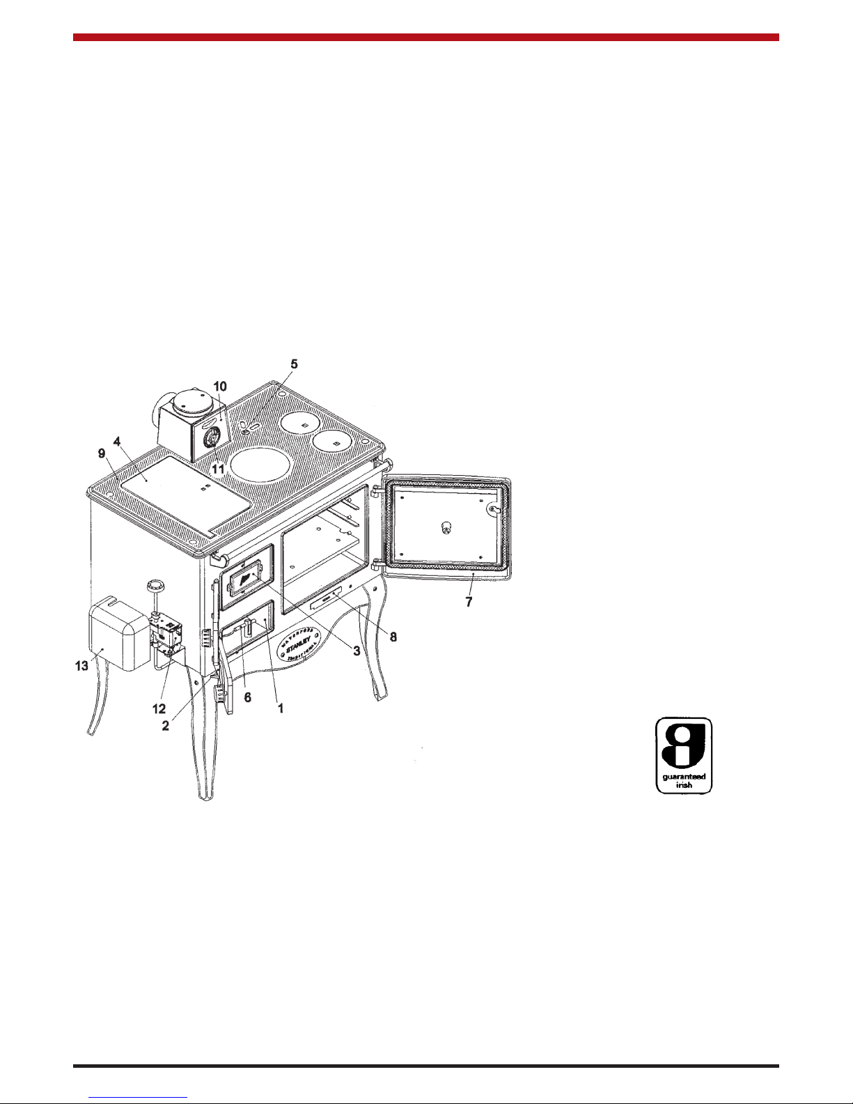
1. Burner Compartment
2. Air Intake Spin Valve
3. Burner Viewing Glass
4. Hot Plate
5. Chimney Damper
6. Fire Valve Phial
7. Oven Door
8. Cleaning Door
9. Hob
10. Bonnet Door
11. Spin Valve
12. Oil Control Valve
13. Oil Control Valve
Cover
14. Fire Valve Bracket
IMPORTANT - CONTROL OF SUBSTANCES HARMFUL TO HEALTH
It is the users/installer responsibility to ensure that the necessary personal protective clothing is worn
when handling materials that could be interpreted as injurious to health and safety.
When handling firebricks, fire cement or fuels use disposable gloves. Exercise caution, use disposable masks and gloves when handling glues and sealants. When working with kerosene oil, fibre
glass or mineral wool. Avoid contact with skin, eyes, nose and throat, use disposable protection.
This cooker is designed for continuous or intermittent use. When cooker is in continuous use, it should
be serviced at least every 6 months. If it is not used for extended periods, the service period may be
extended.
The manufacturers reserve the right to make alterations to design, materials or construction for manufacturing or other reasons, subsequent to publication.
2
Fig.1
Page 4
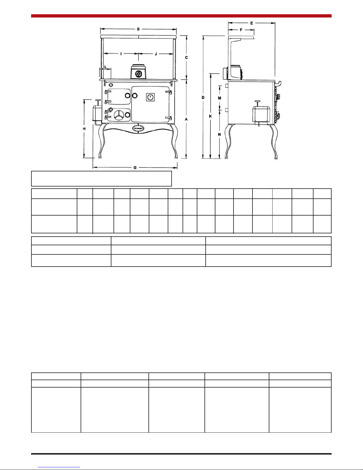
DIMENSIONS ABCDEFGHIJKLMN
METRIC 880 905 508 1388 565 290 990 665 452 452 960 130 260 565
(millimetre)
IMPERIAL
34
5
/8 355/8 20 545/8 221/4 111/2 39 263/4 173/4 173/4 37 3/4 51/8 101/4 221/4
(inches)
FEATURE METRIC IMPERIAL
HOT PLATE 911.25 cm
2
144 in
2
OVEN 400W x 330H x 400D 15
3
/4W x 13H x 153/4D
TECHNICAL DATA
FUEL: Kerosene 28 sec. (Class C2)
CHIMNEY DRAUGHT: 0.02” - 0.06” wg. (0.50mm - 1.5mm)
FLUE DIAMETER: 5” (127mm)
EXIT FLUE GAS TEMPERATURE: 90oC - 200
o
C
BOILER CONSTRUCTION-WHERE APPLICABLE: 6mm & 4mm Mild Steel Plate (HPB)
3MM S/Steel Grade 304 2B (DHW)
TEST PRESSURE OF BOILER: 40 PSI (2.75 Bar)
OPERATING TEMPERATURE LIMIT: 96
0
C (205OF)
BOILER CAPACITY - WHERE APPLICABLE: 7.5 Litres (HPB) or 5.5 Litres (DHW)
COOKER WEIGHT: 232 Kgs (510 lbs)
SPACE HEATING: 3 kW’s (10, 000) Btu’s
Valve Setting Oil Consumption Burner Input Oven Temperature Heat Output to Water
1/h kW (Btu/hr)
o
C kW (Btu/hr)
6 1.14 13.38 (45,690) 225 5.86 (20,000)
5 0.98 11.51 (39,300) 210 4.54 (15,500)
4 0.83 9.74 (33,270) 190 4.10 (14,000)
3 0.67 7.86 (26,850) 145 3.37 (11,500)
2 0.52 6.10 (20,840) 125 1.82 (6,200)
1 0.36 4.23 (14,430) 100 1.49 (5,100)
Fig.2
3
NOTE: Dimensions stated below may be subject
to a slight +/- variation.
All technical data are taken under laboratory conditions and may vary in use, flue draught conditions will effect
performance
CONTINUOUS RUNNING HPB Cooker
SPECIFICATION
Page 5
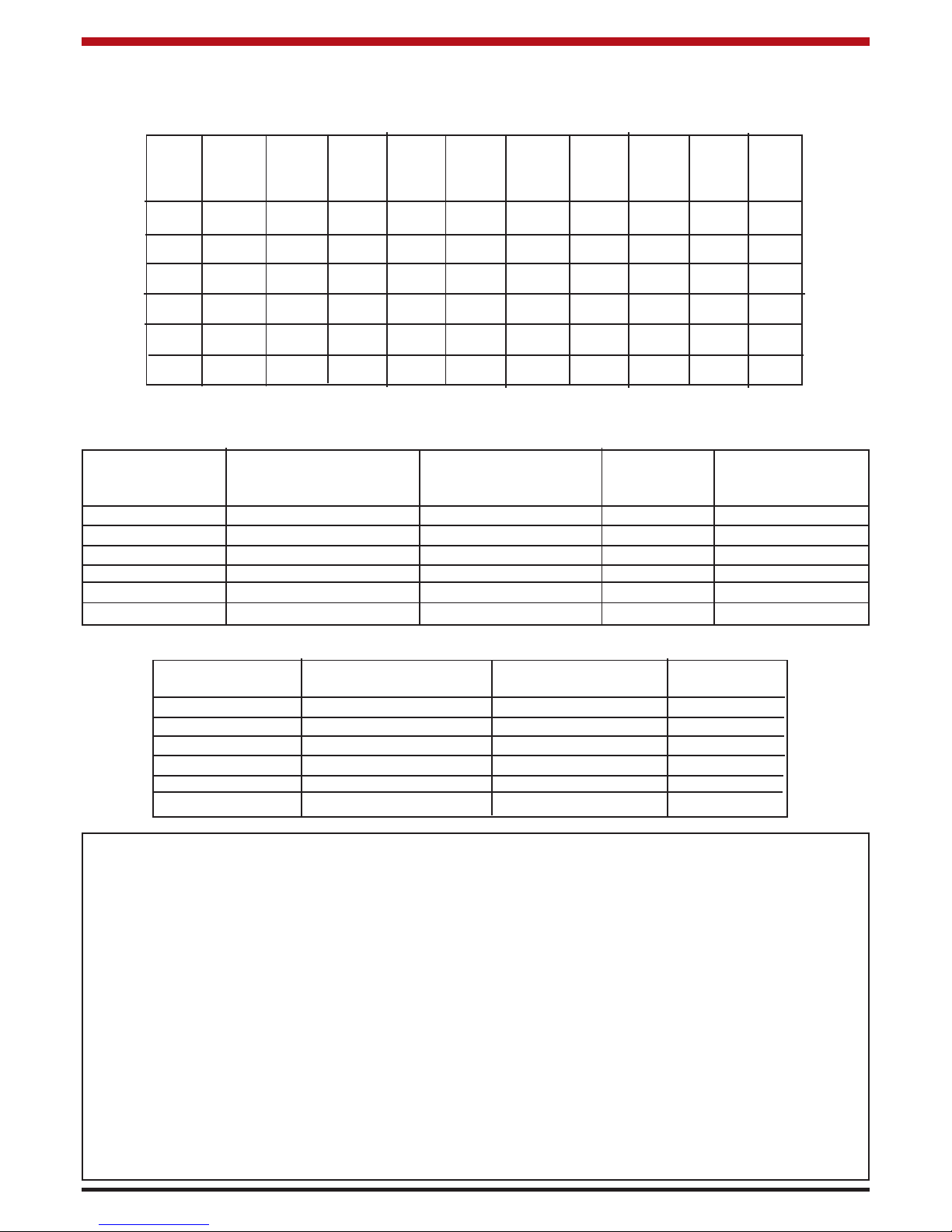
The following table gives approximate cooker heat up times on different settings. (These times are taken with
the cooker running continuously on setting 1 when not in use).
Setting Max.
Temp. 120°C 140°C 160°C 170°C 180°C 190°C 200°C 210°C 220°C
(°C)
6 225 10 20 30 40 50 60 75 100 170
5 210 12 25 35 45 55 70 95 140 ---
4 195 23 40 66 88 126 200 --- --- ---
3 145 45 120 --- --- --- --- --- --- ---
2 125 620 --- --- --- --- --- --- --- ---
1 100 --- --- --- --- --- --- --- --- ---
TIME IN MINUTES
INSTALLATION
As manufacturers and suppliers of cooking and heating appliances, we take every possible care to ensure as
reasonably practicable that these appliances are so designed and constructed as to meet the general Safety
Requirements when properly used and installed.
THE INSTALLATION MUST COMPLY WITH THE FOLLOWING:
* B.S. 5410 Part 1 Oil Installations.
* The Building Regulations: Part J England, Wales.
Part F Section III Scotland.
Part L Northern Ireland.
Part J Ireland.
* The Control of Pollution (Oil) Regulations.
* B.S. 5449 Forced Circulation Hot Water Central Heating System for Domestic Installation.
* Safety, Health and Welfare at Work Act for Ireland, England, Wales & Scotland.
* B.S. 7593: Treatment of Water in Domestic Hot Water Systems.
* B.S. 7074: Part 1 & 2 Hot Water Supply.
* B.S. 4814: Sealed Systems.
4
NOTE: These times may differ subject to draught conditions, oil rates, boiler output and usage.
VALVE SETTING OIL CONSUMPTION BURNER INPUT OVEN TEMP. HEAT OUTPUTS
(L/H) kW (BTU/hr) (oC) TO WATER
kW (BTU/hr)
6 1.02 9.98 (34,040) 230 3.57 (12,180)
5 0.87 8.51 (29,035) 220 3.21 (10,950)
4 0.73 7.14 (24,360) 208 2.89 (9,864)
3 0.58 5.67 (19,355) 179 2.42 (8,290)
2 0.44 4.30 (14,685) 59 0.88 (3,005)
1 0.29 2.84 ( 9,680) 46 0.70 (2,390)
VALVE SETTING OIL CONSUMPTION BURNER INPUT OVEN TEMP.
(L/H) kW (BTU/hr) (
o
C)
6 0.69 6.75 (23,035) 240
5 0.60 5.87 (20,030) 228
4 0.51 4.99 (17,025) 206
3 0.42 4.11 (14,020) 190
2 0.33 3.23 (11,015) 122
1 0.24 2.35 ( 8,010) 66
DHW Cooker
Dry Cooker
Page 6
LOCATION
When choosing a location for this appliance you
must have the following:
A. Sufficient room for installation and servicing.
B. Adequate clearance to combustibles (see
Clearance to Combustibles Section).
C. A satisfactory flue system (See Flues).
D. Fixed fuel supply line and shut off valve (See
Fuel Supply).
E. Adequate air supply to support combustion
(See Ventilation & Combustion Air
Requirements).
F. Solid floor or base of non-combustible mate-
rial which is capable of supporting the total
weight of the stove. (See Hearth
Construction).
Note: When passing through walls or ceilings with
the flue system:
G. Always check for obstructions, for example
electrical fittings, wiring, ducting, plumbing
and fixed furnishings.
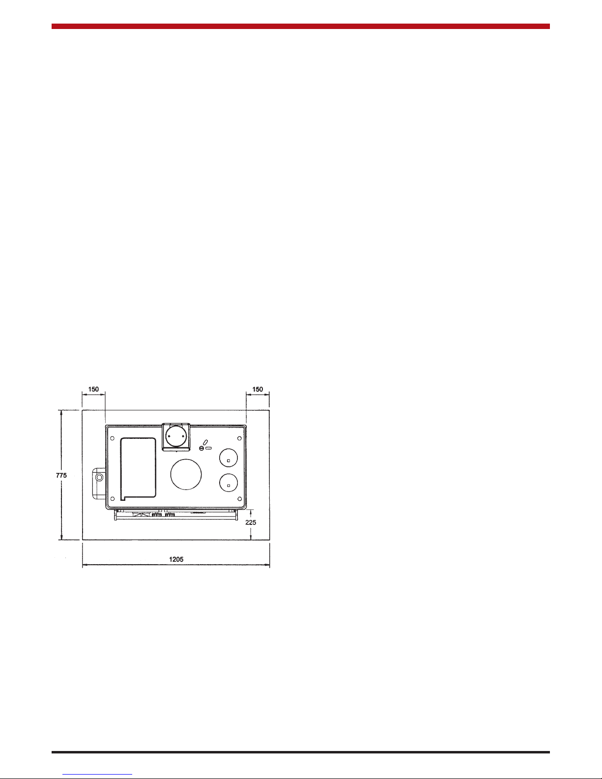
HEARTH CONSTRUCTION
When a properly constructed hearth is not available
we recommend that the cooker be placed on a slab
of framed concrete of 75mm (3”) deep or a slab of
other insulating material. The hearth should be a
minimum size of 1205mm (47”) wide, 775mm (30
1
/2”) length with the cooker located as shown in fig.3
An isolating valve should be fitted at the tank outlet,
in an accessible position so that the oil supply to the
appliance can be shut off if required. This isolating
valve must be of a type suitable for use with oil. (see
fig.4)
Oil storage tanks support must be carried out in
accordance with the tank manufacture recommendations. Tanks should be located in the most unobstructive position possible having taken safety, filling, maintenance and the need, to provide a head of
oil for the burner into consideration.
FUELS
Use only 28 second viscosity kerosene fuel oil to
B.S. 2869 Part 2 class C2 and or equivalent.
FUEL SUPPLY LINE
The oil supply line from the oil storage tank to the
appliance should be of an approved and suitable
pipe with a minimum internal diameter of 8mm
(5/16”) and connected to the oil control valve.
Supply pipes are normally run in annealed copper
tube complying to EN 1057. It can be obtained in
coil or half hard form for use with bending machines.
This pipe can also be obtained with protective plastic sheathing applied. Fittings for copper pipe
should be compression of the flared manipulative
type to B.S. 864: Part 2. Steel pipes complying with
B.S. 1387: 1985, if used, must be protected from
corrosion. Galvanised pipe and fittings must not be
used.
Screwed joints must only be made with taper
threads complying to B.S. 1740 : Part 1.
Jointing materials must be of types intended for use
with oil fuel. Special petroleum - resisting compounds and PTFE tape are suitable. External pipes
should preferably be run with a continuous rise
towards the direction of flow, so that air can be vented off. It is important to avoid high points which
could cause air locks.
Exposed lengths of oil supply pipe must be properly
supported by purpose made clips securely fixed in
place. Metal clips formed so as to hold the pipe on
to a saddle are preferred. Consideration should be
given to avoiding routes which expose the pipe to
severe chilling which could cause freezing of the oil.
Where pipes are buried, they must be protected
from accidental damage. The use of joints underground should be avoided if at all possible. If joints
have to be fitted in pipes laid below ground, access
to them must be provided.
5
Fig.3
FUEL SUPPLY / INSTALLATION
OIL STORAGE TANKS
In order to enable sediment and water to be
removed from steel tanks a drain valve must be fitted.Oil storage tanks made of steel and all connecting equipment (e.g. filling pipes, and vent pipes)
should comply with B.S. 799 Part 5. Galvanised
steel must not be used. Polyethylene (Plastic) tanks
should comply with OFTEC standard OFS T100 and
or equivalent. Oil should never be stored in transulent plastic containers.
Page 7
An oil filter (5 - 10 micron) and stop valve must be fitted to the fuel feed line and located near the supply
tank and facilities should be provided to enable it to
be serviced without draining down the oil supply system. (See fig.4).
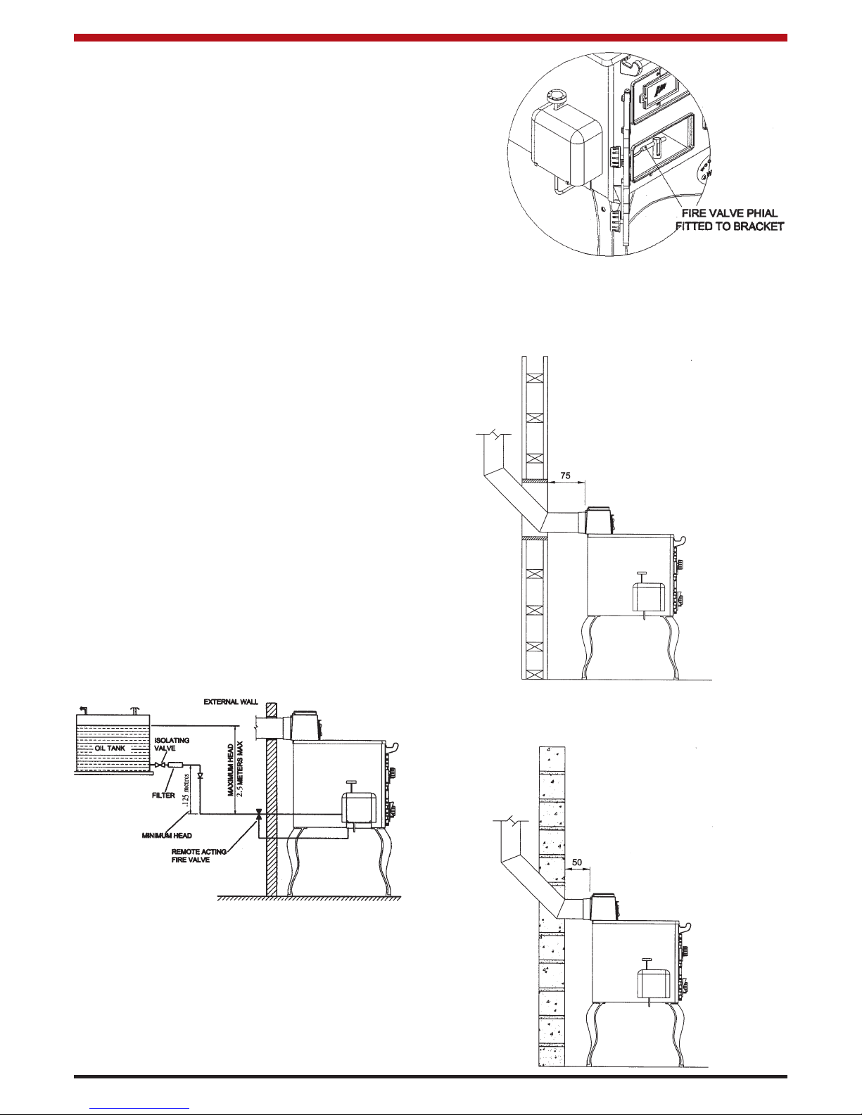
At the point where the oil line enters the building, the
oil line must be fitted with an approved remote acting fire valve which meets the requirements of B.S.
5410 : Part 1, fitted with the appropriate length of
capillary. The temperature rating limit should be
90
o
C. The heat sensoring phial of the fire valve
should be passed through the base of the burner
compartment and fitted through the fire valve bracket provided in the burner compartment (see Fig.5). It
is absolutely essential that the fire valve is located
externally and is as close as possible to the appliance. For existing installations where the oil supply
is built into the structure internally, the remote acting
fire valve should be fitted where the oil supply line is
first exposed internally. This type of layout is not
recommended for new installations.
These requirements are further explained within the
following documents:
* BS 5410: Part : Code of practice for Oil
Firing installations up to 45 kW output
capacity for space heating and hot water
supply purposes.
* OFTEC Technical Information Book Three:
Installation Requirement for Oil Fired Boilers
and Oil Storage Tanks.
* The Building Regulations Part J: England
Wales, Part F - Section 4 Scotland and Part
L Northern Ireland.
CLEARANCES TO COMBUSTIBLES
The minimum clearance to combustible materials
should be maintained at least 75mm (3”) from rear of
cooker (see Fig. 6).
Fig.4
Fig.5
6
Fig.6
The minimum clearance to non-combustible materials should be maintained at least 50mm (2”) from
rear. (see Fig.7)
If there are other oil fired appliances connected to
the oil storage tank especially appliances with oil
pumps e.g. oil fired boilers or stoves, it is recommended that a separate oil supply line is taken from
the oil tank to the cooker. The separate oil supply
line to the cooker will avoid the possibility of the
pumped appliance taking oil from the cooker burner.
A suitable shut off valve should be fitted near the
cooker and be accessible at all times.
NOTE: Ensure that the fire valve phial is not touching any point of the base casting.
Fig.7
Page 8
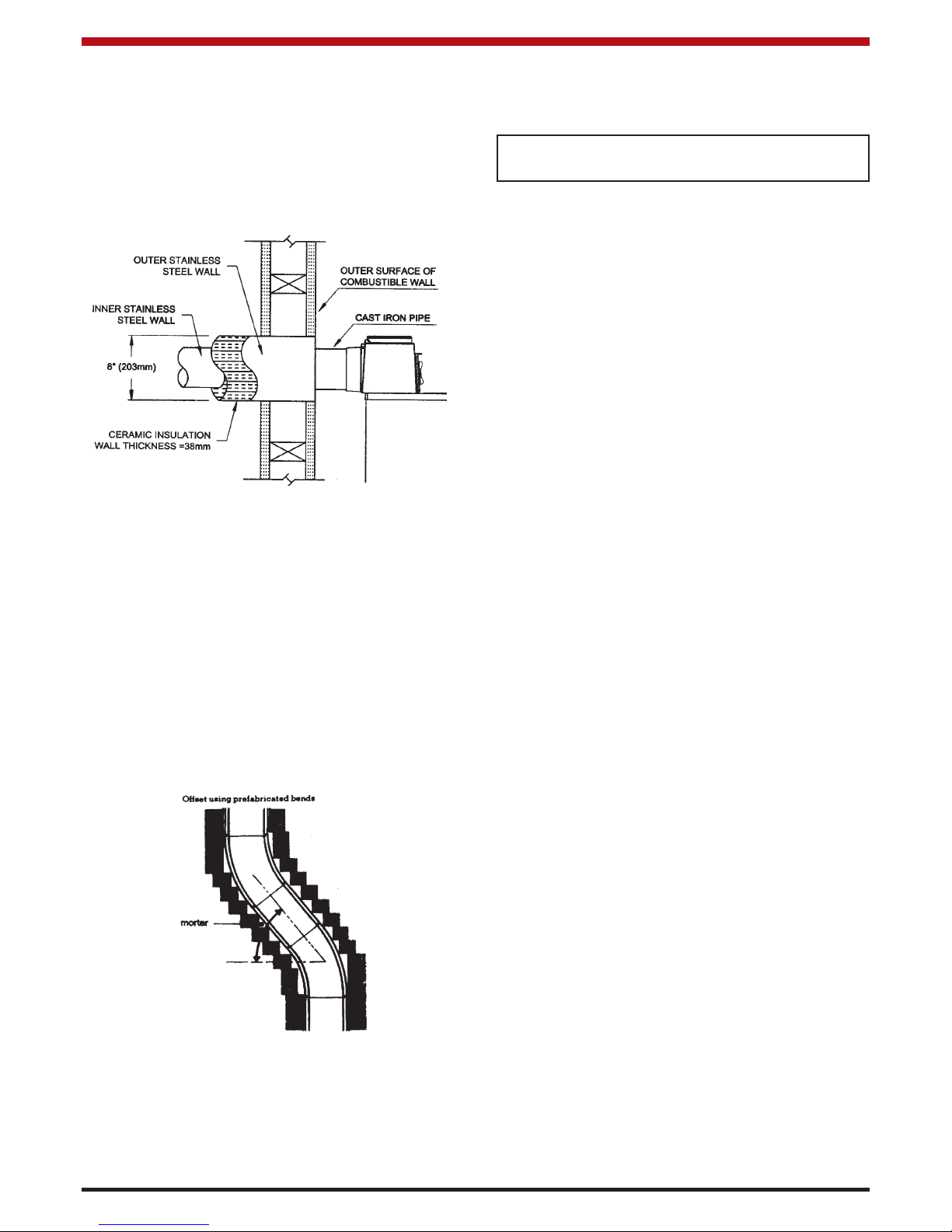
Fig.9
FLUE SYSTEM
Generally the most effective chimney is one that is
straight, avoids offsets, and terminates with a
straight sided pot. Horizontal runs more than
305mm (12”) and 90
o
bends numbering more than 2
per installation should be avoided. Where the standard masonry chimney is not available, a proprietary
type of 125mm (5”) twin wall, fully insulated pipe
may be used.
Flues should be vertical wherever possible and
where a bend is necessary, it should not make an
angle of more than 37.5
o
with the vertical.
Fig.8
Never obstruct free air circulation from around or
entering the cooker grills.
Where the flue passes through a combustible material a twin wall solid packed insulated chimney connector must be used and come flush with the outer
surface material and run all the way to the masonry
chimney or to the point of termination of the factory
made chimney. (see Fig. 8).
may be caused by roof structures, other chimney
stacks etc. The venting terminal position should be
in accordance with Building Regulations BS 5410:
Part 1.
FLUE CLEANING
The flue pipe must be fitted with a cleaning pipe.
The flue must be inspected annually and cleaned
when necessary.
USE OF EXISTING FLUES AND CHIMNEYS
When connecting to an existing chimney it is necessary to line the flue using either 5” (125mm) rigid or
flexible stainless steel flue liner.
An existing flue pipe or chimney that has proved to
be satisfactory when used for solid fuel can normally be used for this appliance provided that its construction, condition and dimensions are acceptable.
Flues that have proven to be unsatisfactory, particularly with regard to down draught, must not be considered for venting this appliance until they have
been examined and any faults corrected. If there is
any doubt about an existing chimney, a smoke test
should be carried out.
Before connecting this appliance to a chimney or
flue pipe which has previously been used with
another fuel, the chimney or flue pipe must be thoroughly swept and/or lined accordingly.
All register plates, restricter plates and dampers etc.
which could obstruct the flue at a future date must
be removed before connecting this appliance.
The combustion products from this appliance will
have a descaling effect on hardened soot deposits
left from burning solid fuels.
ALTHOUGH THE CHIMNEY MAY HAVE BEEN
CLEANED OF LOOSE SOOT PRIOR TO INSTALLATION, IT IS IMPERATIVE THAT THE CHIMNEY
IS INSPECTED FOR SCALED SOOT PARTICLES
AFTER THE FIRST MONTH OF OPERATION AND
ANY LOOSE MATERIALS REMOVED TO AVOID
BLOCKAGE.
NOTE: Never connect to a chimney or flue
system serving another appliance.
7
FLUE HEIGHT
The flue must be high enough 4.5mts (15ft minimum) measured vertically from the appliance outlet
to the top of the flue terminal to allow flue gases to
vent into the clear air, away from turbulence that
A bend should not
make an angle of
more than 37.5
o
with the vertical.
Page 9

8
FLUE LINERS
Chimney’s lined with salt glazed earthenware pipes
are acceptable if the pipes comply with EN 1457 and
must be 125mm (5”). When lining an existing chimney, a liner approved to B.S. 4543, Parts 1, 2, & 3
should be used. The liner should be secured at the
top and bottom by using a closure/clamping plate
firmly sealed and secured, and an approved terminal used at the top.
It is essential that every flue system be inspected
and tested by a competent person for its correct
effectiveness, to ensure that the combustion products are completely discharged to the outside
atmosphere.
SEALING
This cooker and flue system operate under a negative pressure, it is essential that all flue joints are
tightly sealed against flue gas leakage and tested
accordingly.
CONNECTIONS
This appliance may be connected either direct vertical or horizontal. THE HORIZONTAL CONNEC-
TION MUST NOT EXCEED 300MM IN LENGTH.
Blocked chimneys are dangerous. Keep chimneys and flueways clear.
Where an appliance spigot or flue pipe protrudes into the chimney, care should be taken to
ensure that it does not block the chimney.
VENTILATION AND COMBUSTION AIR
REQUIREMENTS
It is imperative that there is sufficient air supply to
the burner of the cooker in order to support correct
combustion.
The air supply to this appliance must comply with
B.S. 5410 Part 1.
The minimum effective air requirement for this appliance is 50 cm
2
. When calculating combustion air
requirements for this appliance use the following
equation: 550mm2per each kW of maximum rated
output above 5 kW. These requirements are illustrated in OFTEC Technical Book No.3 & B.S. 5410
Part 1.
If there is another appliance using air fitted in the
same or adjacent room, it will be necessary to refer
to B.S. 5410 Part 1 to calculate the additional air
supply. All materials used in the manufacture of air
vents should be such that the vent is dimensionally
stable, corrosion resistant, and has no provision for
closure. The effective free area of any vent should
be ascertained before installation.
The effect of any grills should be allowed for when
determining the effective free area of any vent.
Air vents direct to the outside of the building should
be located so that any air current produced will not
pass through normally occupied areas of the room.
An air vent outside the building should not be located less than the dimensions specified within the
Building Regulations and B.S 5410 Part 1 from any
part of any flue terminal. These air vents must also
be satisfactorily fire proofed as per Building
Regulations and BS 5410 Part 1.
Air vents in internal walls should not communicate
with bedrooms, bedsits, toilets, bathrooms or rooms
containing a shower.
Air vents traversing cavity walls should include a
continuous duct across the cavity. The duct should
be installed in such a manner as not to impair the
weather resistance of the cavity.
Joints between air vents and outside walls should be
sealed to prevent the ingress of moisture. Existing
air vents should be of the correct size and unobstructed for the appliance in use. If there is an
extraction fan fitted in the room or adjacent rooms
where this appliance is fitted, additional air vents will
be required to eleviate the possibility of spillage of
products of combustion from the appliance/flue
while the fan is in operation. (Refer to B.S. 5410
Part 1).
Where such an installation exists, a test for spillage
should be made with the fan or fans and other
appliances using air in operation at full rate, (i.e.
extraction fans, tumble dryers) with all external
doors and windows closed.
If spillage occurs following the above operation, an
additional air vent of sufficient size to prevent this
occurrence should be installed. If spillage continues
then the appliance should be shut down and the flue
system examined.
DRAUGHT REQUIREMENTS
The Errigal Oil Cooker requires a steady draught of
:
0.02” wg - 0.06” wg
(0.5mm wg - 1.5mm wg)
When a draught of over 0.06”wg is recorded, the
spin valve on the bonnet door can be opened
(draught stabiliser) allowing the flue pull on the cooker to be reduced. (see Fig. 10)
Page 10

DOWN DRAUGHTS
However well designed, constructed and
positioned, the satisfactory performance of
the flue can be adversely affected by down
draught caused by nearby hills, adjacent tall
buildings or trees. These can deflect wind
to blow directly down the flue to create a
zone of high pressure over the terminal.
(See Fig.11).
A suitable anti-down draught terminal or
cowl will usually effectively combat direct
down draught but no cowl is likely to prevent down draught due to a high pressure
zone.
Ensure that any cowl used will not restrict
the flue exit, or cause excessive back pressure.
Fig.10
FACTORY-MADE INSULATED CHIMNEYS
Factory-made insulated chimneys should be constructed and tested to meet the relevant standards
and recommendations given in:
* B.S. 7566 – Installation of factory-made chimneys
conforming to B.S. 4543 for domestic appliances.
Part 1: Method of specifying installations design
information.
Part 2: Specification for installation design.
Part 3: Specification for site installation.
Part 4: Recommendation for installation design
and installation.
SUITABLE MATERIALS
* Mineral Fibre cement pipes conforming to
B.S 7435.
Fig.11
9
IMPORTANT: THIS APPLIANCE SHOULD NOT
BE CONNECTED TO A CHIMNEY THAT IS
PRONE TO DOWN DRAUGHTING.
Page 11

* Insulated metal chimneys conforming to
B.S.4543 (a galvanised finish is not suitable
for exterior use).
* Clay flue linings conforming to B.S. EN
1457.
* Pre-cast concrete chimney blocks,
incorporated into the building structure. It is
particularly important that the correct
connection block be provided at the base
of the flue conforming to B.S. 3572.
* Cast iron or acid resistant vitreous enamel
lined mild steel conforming to B.S. 41.
* Sheet metal conforming to B.S. 4076.
SAFETY VALVE
A non-adjustable 3 bar safety valve must be fitted to
the primary flow pipe adjacent to boiler connection
ensuring that any discharge will not create a hazard
to occupants or cause damage to electrical components or property.
The use of room thermostats, radiator thermostatic
valves, domestic hot water controllers, etc, can
greatly enhance a heating system and we recommend their use.
Only competent personnel should be employed to
carry out your heating installation.
PIPE FITTINGS
Materials used for installation work should be resistant, sound and should conform to the current editions of the following or their equivalent.
1.1 Ferrous Materials
BS 4127 Stainless steel tubes.
BS 1387 Steel tubes.
BS 1740 Steel pipe fittings.
BS 6956 Jointing Materials
1.2 Non-Ferrous Materials.
EN 29453 Soft Solder Alloys .
BS 864 Compression tube fittings.
BS 2871 & BS E.N. 1057 Copper and
Copper Alloys.
INDIRECT DOMESTIC CYLINDER
This cooker can only be connected to an in-direct
domestic cylinder of 136 litres (30 gallons).
See Fig. 12.
Fig.12
10
HEATING
Care should be taken to ensure that the heating system is correctly installed and that it complies with all
relevant codes of practice.
Note: We strongly advise the use of pipe lagging if
the installation is likely to be exposed to situations
where the temperature will dip to a level consistent
with frost.
The HPB model produces up to 5.8 kW to water on
maximum setting therefore it is necessary to fit a
heat sink radiator. See output on page 3.
DIRECT DOMESTIC CYLINDER (DHW MODEL
ONLY)
A 113 litre (30 gallon) direct domestic cylinder can be
connected to this cooker. (See Fig. 13)
Fig.13
Errigal
Oil
Cooker
(HPB Model)
Errigal
Oil
Cooker
(DHW Model)
Page 12

GENERAL MAINTENANCE
It is important that the user is familiar with their heating system and that they ensure regular checks and
maintenance are carried out, which can limit unnecessary breakdowns.
We recommend that you evaluate the overall insulation in your house, i.e. attic, external walls, window
and external doors.
Insulation and draught proofing can greatly reduce
running costs while equally enhancing living conditions.
DRAINING
Key operated drain taps conforming to B.S. 2879,
should be provided in an accessible position in all
low parts of the system. However, it should be noted
that there may be short sections, e.g. when passing
under doorways that may not be possible to drain.
PRE-INSTALLATION ASSEMBLY
1. Remove packing strip from the top of cooker.
Remove all loose components supplied from
the top of the cooker and the oven. Remove
all doors. (See Fig.15)
Fig.16
FITTING OF LEGS
11
Fig. 15
INTERLINK SYSTEM
Fig.14
Errigal Oil
Cooker
Page 13

2. Place cement blocks or other strong supports about 458mm (13”) high behind the
cooker. Space the supports behind it and lay
the cooker on its back. (See Fig.16)
3. Fit the four legs to the four base corners
using the hexagon-head bolts and washers.
Note: Ensure that each of the front legs has a screw
hole in the front.
4. Join the two sections of the front skirting
together by screwing the name-plate with its
back fixing strip into position between the
two sections and secure the two sections
tightly to the name-plate.
5. Fit the complete skirting under the front of
the range inside the front legs using a screw
and nut to secure it to each leg. (See Fig.17)
6. Lift cooker off the supports. Stand it upright
without putting any strain on the legs.
10. Move the cooker into position for installation,
taking care not to damage the legs. Ensure
that all the requirements in section 5 have
been met.
11. Place the oblong hotplate, simmering plate
and the two round cleaning cups in position.
12. Place the bonnet in position and fit the bonnet door with flue damper to the front of it.
Seal the bonnet when in place, with cement.
Depending on the flue configuration
required, top or back, the blanking plate is
fitted to the top or back of the bonnet. (See
Fig.19)
12
Fig.17
Fig.18
7. Bolt the float valve bracket to the underside
of the base using the two
1
/2
” x
1
/4
” round
head screws provided. (See Fig.18).
8. Connect the formed fuel line to the control
valve outlet and the elbow connection in the
burner compartment, running the fuel line
through the slot provided in the burner compartment base. Seal both connections using
a suitable jointing compound.
9. FIT THE REMOTE ACTING FIRE VALVE
PHIAL THROUGH THE SAME SLOT AS
THE FORMED FUEL LINE. ENSURE THAT
THE FIRE VALVE PHIAL IS FITTED
THROUGH THE FIRE VALVE CLIP SO
THAT NO PART OF THE PHIAL TOUCHES
THE BASE.
Fig.19
13. Screw the towel rail brackets to the top front
of the cooker and fix the towel rail in position
between the brackets. Tighten up the
screws.
14. Hang the fire door and the ashpit door on
their hinges.
15. Place the oven shelves in position with the
cast iron shelf below the sheet steel shelf.
16. Place the cleaning door in position beneath
the oven door.
17. Connect the fuel line to the control valve
inlet.
18. Check all joints on fuel line for leaks before
completion of installation.
19. Connect and seal the flue to the bonnet.
Page 14

COMMISSIONING
Burner Set-up
1. Using a spirit level, check that the control
valve is level in all directions. Adjust the
locking nuts on the valve legs if levelling is
necessary. (See Fig.20).
Fig..20
Fig.21
2. Check that the burner is level in all directions. If levelling is necessary remove the
fire valve phial from the fire valve bracket
and place it to one side of burner compartment. Loosen the 1/4” bolt, holding down
the burner stand. The level is adjusted by
adjusting the three M8 bolts on the base of
the burner stand (See Fig. 22). Re-tighten
the 1/4” bolt when finished adjusting the
M8 bolts.
Fig.22
13
3. Push the control valve trigger up to set the
valve (See Fig.20). Turn the control knob
to 6 for 10 minutes to commence filling the
burner. If oil does not flow to the central
reservoir after 5 minutes, it may be necessary to bleed the oil line at the elbow connector in the burner compartment.
4. Check the oil in the burner rings. The oil
level should be 4mm. (See Fig. 23). If the
level is greater than required, the control
valve should be lowered. The control valve
bracket can be moved up and down by loosening the M4 lock nuts. If the level is less
than required, the control valve should be
raised until the oil level is correct. Each time
an adjustment is made, the oil in the central
reservoir and burner rings should be soaked
up with absorbent paper and the filling
process repeated.
Note: Do not check oil depth adjacent to fuel ports.
Fig.23
5. After any adjustments to the control valve,
check that it is level in all directions.
6. Once the oil depth and burner level are set,
the burner can be re-assembled. Refer to
Burner Assembly section.
7. Attach the control spindle to the control valve
using the M8 lock nut, and place the oil control valve cover in place over the valve.
Page 15

8. Turn the control valve to 6 and after 10 minutes, light the stove through the lighting
port as shown in Fig.25.
14
Fig.25
Fig.26
9. Adjust the spin valve opening until a blue
flame with yellow tip is obtained around the
outer shell. (See Fig. 26). The spin valve
should be set for an opening of approximately 6mm. (This may vary slightly depending
on flue draught performance).
10. Check that the Bacharach smoke number is
<2.
WARNING: OPEN DIRECT FLUE DAMPER
WHEN LIGHTING. SEE FIG.24.
Note: Ensure that the lighting port is closed
after the stove is lit.
Fig.24
ALWAYS OPEN THE DIRECT FLUE DAMPER
BEFORE LIGHTING THE COOKER. NEVER RELIGHT THE COOKER UNTIL IT IS COMPLETELY
COOLED DOWN. (SEE FIG. 24)
BURNER ASSEMBLY
With the burner level and the correct depth of oil in
the burner rings, the following tips should be followed for assembling the burner.
1. Replace the wicks in the burner rings.
Ensure that the cut-outs in the wicks line up
with the fuel ports between the central reservoir, and the burner rings. (See Fig.27)
2. Replace the cast iron centre well cap, grinding it into position to ensure it sits down properly.
3. Fit the outer shell, ensuring that it sits firmly
on the burner base and that it does not interfere with the outer wick. The outer shell is
fitted such that the lighting port is offset to
the right of the burner. (See Fig. 28).
4. Fit the remaining burner shells ensuring that
the seams are staggered as shown in Fig.28.
Ensure that all the shells sit firmly on the
burner base and that they do not interfere
with the wicks.
Fig.27
Page 16

5. Fit the burner baffle and the burner lid
on top of the shells. (See Fig.29).
When the stove has reached a stable condition (on
setting 6), the burner shells should glow red.
If the flame is yellow/orange in colour, there is not
sufficient air supply to the burner and the spin valve
on the ashpit door should be adjusted.
If after adjusting the spin valve, there is still a yellow/orange flame, consult the Fault Finding Section
of this manual.
Fig.29
COOKER OPERATION
Lighting the Cooker
1. Turn the control valve to setting 6 (anti-clock
wise) and allow 10 minutes for the burner to
fill.
2. Light the burner by putting a lighted paper or
taper through the lighting port (See Fig.25).
3. When the cooker is up to temperature, i.e.
when the burner shells are red, close the
direct flue damper and turn the control valve
(clockwise) to the desired setting.
Note: It is advisable that the control valve is set for
setting 1 or 2 when the cooker is not being used in
order to reduce the heat-up time when cooker operation is required. Running the cooker at 1 or 2 will
keep the flue system warm and help maintain flue
buoyancy.
15
Fig.30
ALWAYS OPEN THE DIRECT FLUE DAMPER
BEFORE LIGHTING THE COOKER. NEVER RELIGHT THE COOKER UNTIL IT IS COMPLETELY
COOLED DOWN. (SEE FIG. 24)
Note: The angle on the DHW/Dry baffle is directed
towards the oven. See Fig. 29.
DHW AND DRY HPB
Fig.28
6. Place the air distribution baffle in the burner
compartment ensuring that it sits on top of
the carbon leg assembly fuel line. Ensure
that it is kept to the left side of the burner
compartment so that the lighting port can be
accessed.
FLAME PATTERN
The flame pattern should consist of a blue flame with
a yellow tip around the burner baffle.
NOTE: NEVER OPERATE THE COOKER ON
SETTING 1 WITH THE DIRECT DAMPER
CLOSED.
TURNING THE COOKER OFF
When the control valve is turned to 0, the oil feed to
the burner is cut off and the cooker goes out.
SERVICING
To ensure continued efficient and safe operation of
the appliance, it is recommended that it is checked
and serviced by an Authorised Stanley Service
Engineer. This stove should be serviced at least
every 6 months. However if the stove is not used for
long periods of time, the service period may be
extended.
The cooker must be cold before servicing. Allow 34 hours for the cooker to cool.
NOTE: TO AVOID VIOLENT IGNITION DO NOT
RESTART UNTIL COOKER HAS COMPLETELY
COOLED DOWN.
Page 17

Fig.31
Fig.33
16
Fig.32
1. Open the oblong hotplate and remove the
burner shells, wicks, centre well cap, baffle and burner lid from the fire box.
2. Open the ashpit door and place the fire
valve phial to one side of the burner compartment, so that the burner base can be
accessed. Remove the air distribution baffle.
3. Disconnect the oil line from the burner and
remove the burner from the firebox by undoing the M8 bolt on the side of the burner support frame (See Fig.31).
4. Remove any dirt from the burner rings and
ensure that the ports between the rings are
clear.
5. Remove the simmering plate and cleaning
cups and brush any soot deposits into the
firebox.
Vacuum any dirt from the firebox base and if
necessary, clean the viewing glass.
6. Remove the base cleaning door and rake the
deposits, from underneath the oven through
the cooker front into a container using the
scraper tool. (See Fig.32).
7. Open the bonnet door and check for any soot
deposits in the flue. If there is evidence of
substantial soot build-up, the flue may need
to be cleaned.
8. Replace the burner in the firebox and reconnect the oil line to the burner.
9. Check that the burner and oil control valve
are level in all directions. Check all oil connections to ensure that there are no leaks.
(See Fig.33).
10. Turn the control valve to 6 to fill the burner.
Check that the correct level of oil is present.
(See Commissioning Section.)
11. Fit new wicks in the burner rings, ensuring
that the cut-outs in the wicks line up with the
fuel ports between the burner rings. (The
wicks should be replaced every time the
cooker is serviced).
12. Fit the burner assembly as described in the
Burner Assembly Section.
13. Reposition the fire valve phial. Close the
ashpit door.
14. Light the stove and check the flame pattern
(See Commissioning Section).
Flexible oil lines should be inspected at each
and every service visit. There are varying types
of line with guarantee periods between 1 and 5
years. It is important in the interest of safety that
flexible lines are changed at regular intervals.
Inspect for date code stamp and if the line is out
of its guarantee period or shows signs of being
kinked or damaged, replace immediately.
Page 18

Note: The flow rate should not exceed 20 cc/min as
this will overheat the cooker and the control
equipment for the cooker.
When the required rates are obtained, the oil
line should be reconnected ensuring that
there are no leaks and that the level of the
control valve has not been affected.
VITREOUS ENAMEL CLEANING
General cleaning must be carried out when the
stove is cool.
If this stove is finished in a high gloss vitreous enamel, to keep the enamel in the best condition observe
the following tips:
1. Wipe over daily with a soapy damp cloth,
followed by a polish with a clean dry duster.
2. For stubborn deposits a soap impregnated
pad can be carefully used on the vitreous
enamel.
3. DO NOT USE ABRASIVE PADS OR OVEN
CLEANSERS CONTAINING CITRIC ACID
ON ENAMELLED SURFACES. ENSURE
THAT THE CLEANSER MANUFACTUR
ERS INSTRUCTIONS ARE ADHERED TO.
17
Fig.35
1. Disconnect the oil feed at the exit from the
control valve. (See Fig.34)
2. Place the collection vessel beneath the con
trol valve to catch the oil. Turn the control
valve to 6 and start the stopwatch when the
first drop of oil falls into the vessel.
3. Measure the oil flow for 5 minutes. (consult
table below for current rate).
4. Turn the control valve to 1 and repeat the
above procedure.
5. If either of the above rates is not correct, the
control valve can be adjusted. The high rate
screw is located above the control knob with
the low rate located below the control knob.
(See Fig.35) The screws are very sensitive
and the measurement procedure should be
carried out after each adjustment. The rates
are increased by turning the screws anti
clock-wise and decreased by turning the
screws clock-wise.
Setting Flow Rate
HPB DHW DRY
1 6cc/min 5cc/min 4cc/min
6 19cc/min 17cc/min 11.5cc/min
Fig.34
CONTROL VALVE RATING
The control valve must be rated by the
Commissioning Agent on site to give the required
fuel input for the cooker.
When the flame pattern is unsatisfactory, the air supply to the burner and flue passages should be thoroughly investigated before investigating the oil feed
rate to the burner.
Check the oil feed rate as follows:
Note: Great care should be taken to ensure the
accuracy of the flow rate, as it greatly affects
the cooker performance.
Apparatus Required: Collection Vessel
Stopwatch
Graduated Cylinder (capable
of measuring 150ml and graduated to the nearest ml)
Small flat screwdriver.
Page 19

18
ERRIGAL OIL 20K EXPLODED VIEW
1. Oven Door
2. Spin Valve
3. Ashpit Door
4. Fire Door
5. Door Hinge
6. Door Knob
7. Fire Valve
8. Fire Valve Bracket
9. Air Distribution Baffle
10. Front
11. Towel Rail Bracket
12. Towel Rail
13. Door Knob Washer
14. Door Knob Spacer
15. Base Cleaning Door
16. Door Knob Locking
Nut
17. Door Catch
18. Oven Door Panel
19. Thermometer
20. Oven Bottom
21. Oven Shelves
22. Plinth R.H.S.
23. Nameplate
24. Plinth L.H.S.
25. Plinth Joining Clip
26. S.I. Base Protection Plate
27. Legs
28. Base
29. Sheet Iron Sides
30. R.H. Oven Side
31. Oven End Flue Bottom
32. Oven End Flue Top
33. Ashpit L.H.S.
34. Formed Fuel Line
35. Control Valve Bracket
36. Control Valve Cover
37. Control Knob
38. Oil Control Valve
39. 1/4” x 8mm Compression
Fitting
40. Ashpit R.H.S.
41. Flue Check
42. Grate Support Frame
43. Oven Back
44. Flue Back
45. LH Oven Side
46. Back Sealing Plate
47. Small Back Panel
48. Oven Top
49. Direct Damper
50. Ashpit Back
51. R.H. Window Frame
52. Viewing Glass Frame
53. Viewing Glass
54. L.H. Window Frame
55. S90 Boiler
56. Hob
57. Hob Rod Caps
58. Simmering Plate
59. Flue Deflector Plate
60. Hotplate
61. Bonnet Spin Valve
62. Bonnet Door
63. Bonnet
64. Back Outlet Adapter
65. Bonnet Blanking Plate
66. Bonnet Top Spigot
67. Boiler Rest
68. Large Back Panel
69. Cleaning Cup
70. Burner Stand
71. 1/4” x 8mm Compression
Elbow
72. Burner Pot Elbow Adapter
73. Carbon Leg Assembly
74. Bonnet Gasket
75. Centre Well Cap
76. 8mm Olive
77. 8mm Compression Nut
78. Burner
79. Wicks
80. Burner Shells
81. Burner Lid
82. Burner Baffle
83. Fixing Bolts
Page 20

ERRIGAL OIL DHW EXPLODED VIEW
1. Oven Door
2. Spin Valve
3. Ashpit Door
4. Fire Door
5. Door Hinge
6. Door Knob
7. Fire Valve
8. Fire Valve Clip
9. Air Distribution
Baffle
10. Front
11. Towel Rail Bracket
12. Towel Rail
13. Door Knob
Washer
14. Door Knob Spacer
15. Base Cleaning
Door
16. Door Knob
Locking Nut
17. Door Catch
18. Oven Door Panel
19. Thermometer
20. Oven Bottom
21. Oven Shelves
22. Plinth R.H.S.
23. Nameplate
24. Plinth L.H.S.
25. Plinth Joining Clip
26. S.I. Base Protection
Plate
27. Legs
28. Base
29. Sheet Iron Sides
30. R.H. Oven Side
31. Oven End Flue
Bottom
32. Oven End Flue Top
33. Ashpit L.H.S.
34. Formed Fuel line
35. Control Valve
Bracket
36. Control Valve Cover
37. Control Knob
38. Oil Control Valve
39. 1/4” x 8mm
Compression Fitting
40. Ashpit R.H.S.
41. Flue Check
42. Grate Support Frame
43. Oven Back
44. Flue Back
45. L.H. Oven Side
46. Back Sealing Plate
47. Small Back Panel
48. Oven Top
49. Direct Damper
50. Ashpit Back
51. R.H. Window Frame
52. Viewing Glass Frame
53. Viewing Glass
54. L.H. Window Frame
55. Superette Boiler
56. Hob
57. Hob Rod Caps
58. Simmering Plate
59. Flue Deflector Plate
60. Hotplate
61. Bonnet Spin Valve
62. Bonnet Door
63. Bonnet
64. Back Outlet Adapter
65. Bonnet Blanking
Plate
66. Bonnet Top Spigot
67. Boiler Rest
68. Large Back Panel
69. Cleaning Cup
70. Burner Stand
71. 1/4” x 8mm
Compression Elbow
72. Burner Pot Elbow
Adapter
73. Carton Leg Assembly
74. Bonnet Gasket
75. Center Wall Cap
76. 8mm Olive
77. 8mm Compression
Nut
78. Burner
79. Wicks
80. Burner Shells
81. Burner Lid
82. Burner Baffle
83. Burner Support Rod
19
Page 21

ERRIGAL OIL DRY EXPLODED VIEW
17. Door Catch
18. Oven Door Panel
19. Thermometer
20. Oven Bottom
21. Oven Shelves
22. Plinth R.H.S.
23. Nameplate
24. Plinth L.H.S.
25. Plinth Joining Clip
26. S.I. Base Protection
Plate
27. Legs
28. Base
29. Sheet Iron Sides
30. R.H. Oven Side
31. Oven End Flue
Bottom
32. Oven End Flue Top
33. Ashpit L.H.S.
34. Formed Fuel line
35. Control Valve
Bracket
36. Control Valve Cover
37. Control Knob
38. Oil Control Valve
39. 1/4” x 8mm
Compression Fitting
40. Ashpit R.H.S.
41. Flue Check
42. Grate Support Frame
43. Oven Back
44. Flue Back
45. L.H. Oven Side
46. Back Sealing Plate
47. Small Back Panel
48. Oven Top
49. Direct Damper
50. Ashpit Back
51. R.H. Window Frame
52. Viewing Glass Frame
53. Viewing Glass
54. L.H. Window Frame
55. Sham Cheek
56. Hob
57. Hob Rod Caps
58. Simmering Plate
59. Flue Deflector Plate
60. Hotplate
61. Bonnet Spin Valve
62. Bonnet Door
63. Bonnet
64. Back Outlet Adapter
65. Bonnet Blanking
Plate
66. Bonnet Top Spigot
67. RHS Back Fire Brick
(S90 No.2)
68. Back Panel
69. Cleaning Cup
70. Burner Stand
71. 1/4” x 8mm
Compression Elbow
72. Burner Pot Elbow
Adapter
73. Carton Leg Assembly
74. Bonnet Gasket
75. Center Wall Cap
76. 8mm Olive
77. 8mm Compression
Nut
78. Burner
79. Wicks
80. Burner Shells
81. Burner Lid
82. Burner Baffle
83. RHS Front Fire Brick
(S90 No.3)
84. Back Bottom Brick
85. Back Top Brick
86. Boiler Tapping
Blanking Plates
87. Burner Support Rod
1. Oven Door
2. Spin Valve
3. Ashpit Door
4. Fire Door
5. Door Hinge
6. Door Knob
7. Fire Valve
8. Fire Valve Bracket
9. Air Distribution
Baffle
10. Front
11. Towel Rail Bracket
12. Towel Rail
13. Door Knob
Washer
14. Door Knob Spacer
15. Base Cleaning
Door
16. Door Knob
Locking Nut
20
Page 22

21
FAULT FINDING
If the stove exhibits any of the following conditions, call your Commissioning Engineer.
PROBLEM CAUSE REMEDY
Stove will not light or goes No Oil in the Tank Fill Tank
out when lighting
Fire Valves off Reset valves, check for
cause of over temperature
Control valve trigger down (off) Reset trigger
Oil feed line filter blocked Free Oil filter
Fuel Line Air Locked Bleed Fuel Line
Carbon Leg Blocked Clean Carbon Leg Assembly
(Stove needs service)
Incorrect Depth of Oil in Burner Increase oil level to 4mm
Base
Down Draught in Flue Fit Anti-Down Draught Cowl
Flames burning under burner Incorrect Chimney Draught Check joint seals, increase
chimney height, adjust flue
bonnet spin valve.
Down Draught in Flue Fit Anti-Down Draught Cowl
Oil level too high in burner base Decrease oil level to 4mm
Oil Rate too high Lower control valve fuel input
rate
Dirty or Unstable Flame, Viewing Incorrect Chimney Draught Check joint seals, increase
Glass sooting up Chimney height, adjust flue
bonnet spin valve.
Incorrect Fuel Input Rate Check Fuel Input Rate, adjust
if necessary
Incorrect Spin Valve Setting Adjust Spin Valve Setting
Shells or Vapour Chamber Lid Ensure all shells are seated
not seated properly on Burner base and that their
seams are staggered.
Lighting Port Open Close Lighting Port
Wrong Grade of Oil Used Only Use Kerosene 28 sec C2
Wicks incorrectly Positioned Ensure that the cut-outs in the
wicks are properly aligned
and that the shells don’t
interfere with the wicks
Oil Smell Apparent Incorrect Chimney Draught Check joint seals, increase
chimney height, adjust the
bonnet spin valve.
Down Draught in Flue Fit Anti-Down Draught Cowl
Incorrect Fuel Input Rate Check fuel input rate, adjust if
necessary
Fuel Leaks Check all fuel pipe connec-
tions, and reseal if necessary.
Cooker Overheating Incorrect Fuel Input Rate Decrease Fuel Input Rate
Page 23

22
INSTALLATION CHECK LIST
Flue System
1. Minimum Flue Height of 4.6 metres (15 feet).
2. If connecting to an existing chimney, the chimney should be lined using either a flexible or rigid
125mm (5”) diameter suitable for oil-fired appliances that terminates in excess of 0.6 metres from the
nearest point of the roof, measured vertically and in excess of 2.3 metres measured horizontally.
3. If using an external flue, the appliance should be connected to a 125mm (5”) diameter rigid insulated
flue pipe, suitable for an oil-fired appliance, that terminates in excess of 0.6 metres from the nearest
point on the roof, measured vertically and in excess of 2.3 metres measured horizontally.
4. Any Horizontal flue sections should not exceed 300mm (12”).
5. The chimney serving this appliance should not serve any other appliance.
6. Connection of the flue should only be made through the bonnet on top of the cooker.
7. A suitable flue terminal, such as an OH cowl, should be fitted at the flue termination point.
8. If using an internal flue or chimney, closure-clamping plates should be used to seal the top &
bottom of the chimney.
9. Access should be provided to the chimney serving the appliance to allow for cleaning.
10. If the flue passes through a combustible wall, a twin wall insulated connector must be used and
come flush to the external surface of the wall.
11. The flue should be capable of producing a continuous draught of 0.06” w.g. during normal operation.
Location
1. Clearance to combustible materials must be adhered to as described in the Clearance to Combustibles
Section.
2. The cooker should be installed as to allow adequate air circulation around the cooker and to allow
access for installation & servicing.
3. The cooker must be installed on a non-combustible insulated floor protector that covers the area under
the cooker and extends 6” from the side and back and 9” from the front of the cooker.
Plumbing (Boiler Models Only)
1. Appliance must be connected to a gravity circuit supplying a 113 litre (30 gallon) cylinder using 1” ID
flow & return piping.
2. The length of pipes from the cylinder to the stove should not exceed 7.8 metres (25 feet).
3. A three bar safety valve must be fitted to the primary flow pipe adjacent to the boiler connection on
the stove.
4. The HPB model must be connected to a central heating circuit with a pipe stat, fitted on the feed pipe
to the cylinder, controlling a pump fitted on the return pipe from the central heating circuit.
Ventilation & Combustion Air Requirements
1. The room in which the appliance is located should have an air vent of adequate size to support correct
combustion when all other air-using appliances are operating at full capacity (see Ventilation &
Combustion Air Requirement Section for specific details).
Oil Supply
1. The oil supply tank should be fitted with an isolating valve and filter and should be positioned as to give
a minimum head of oil of 125mm (see Fuel Supply Line section).
2. The stove should be connected to a supply line with a minimum internal diameter of 8mm and must be
fitted with a remote acting fire valve.
3. Where other oil fired appliances are connected to the same oil supply tank, a separate oil supply line
should be taken from the tank to the stove.
Tick
√
Page 24

Rev:006 DP 070126
N00184AXX
23
Manufactured by
Waterford Stanley Ltd.,
Unit 210, IDA Industrial Estate, Cork Road,
Waterford, Ireland.
Tel: (051) 302300 Fax (051) 302315
 Loading...