

Page 1
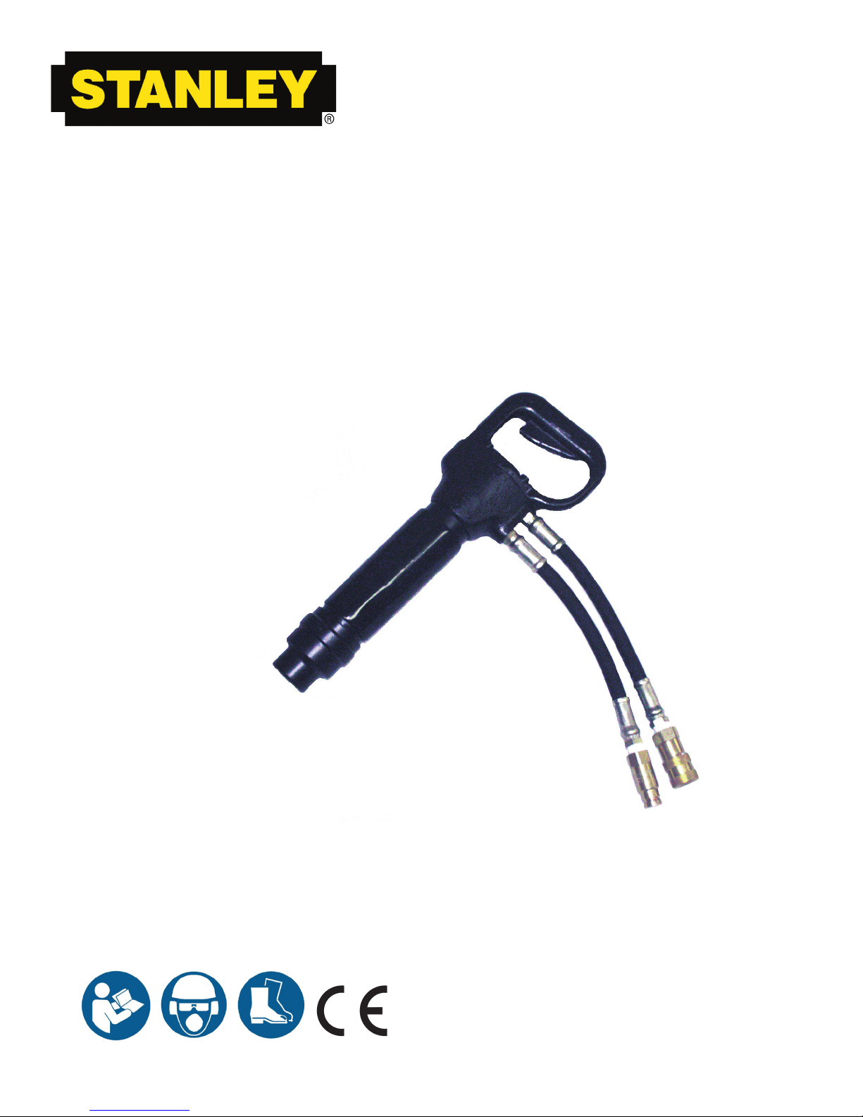
CH15
HYDRAULIC
CHIPPING
HAMMER
Safety, OperatiOn and Maintenance
USer ManUaL
© 2010 Stanley Black & Decker, Inc.
New Britain, CT 06053
U.S.A.
36098 12/2012 Ver. 12
Page 2
DECLARATION OF CONFORMITY
DECLARATION OF CONFORMITY
ÜBEREINSTIMMUNGS-ERKLARUNG
DECLARATION DE CONFORMITE CEE
DECLARACION DE CONFORMIDAD
DICHIARAZIONE DI CONFORMITA
Hydraulic Tools
______________________________________________________________________
I, the undersigned:
Ich, der Unterzeichnende:
Je soussigné:
El abajo firmante:
lo sottoscritto:
Weisbeck, Andy
Surname and First names/Familiennname und Vornamen/Nom et prénom/ Nombre y apellido/Cognome e nom e
hereby declare that the equipment specified hereunder:
bestätige hiermit, daß erklaren Produkt genannten Werk oder Gerät:
déclare que l’équipement visé ci-dessous:
Por la presente declaro que el equipo se especifica a continuación:
Dichiaro che le apparecchiature specificate di seguito:
1. Category:
Chipping Hammer, Hydraulic
Kategorie:
Catégorie:
Categoria:
Categoria:
2. Make/Marke/Marque/Marca/Marca
Stanley
3. Type/Typ/Type/Tipo/Tipo:
CH1513101, CH1513101D, CH1533101, CH1553101
4. Serial number of equipment:
Seriennummer des Geräts:
Numéro de série de l’équipement:
Numero de serie del equipo:
Matricola dell´attrezzatura:
All
5. Mass/Masse/Masse/Masa/Massa 8 kg
Has been manufactured in conformity with
Wurde hergestellt in Übereinstimmung mit
Est fabriqué conformément
Ha sido fabricado de acuerdo con
E’ stata costruita in conformitá con
Directive/Standards
Richtlinie/Standards
Directives/Normes
Directriz/Los Normas
Direttiva/Norme
No.
Nr
Numéro
No
n.
Approved body
Prüfung durch
Organisme agréé
Aprobado
Collaudato
ISO
Noise Directive
Machinery Directive
11148-4:2010
2000/14/EC:2005
2006/42/EC:2006
Self
AkustikNet (Notified body ID 1585)
Bagsvard Hovedgade 141, 2880 Bagsvard, Denmark
Certificate #863/2011/006
Self
6. Special Provisions: None 7. Measurements: Measured Sound Power Level 104 LwA
Spezielle Bestimmungen: Messungen Guaranteed Sound Power Level 105 LwA
Dispositions particulières: Mesures Measured in accordance to Directive 2000/14/EC
Provisiones especiales: Mediciones
Disposizioni speciali: Misurazioni
8. Representative in the Union: Patrick Vervier, Stanley Dubuis 17-19, rue Jules Berthonneau-BP 3406 41034 Blois Cedex, France.
Vertreter in der Union/Représentant dans l’union/Representante en la Union/Rappresentante presso l’Unione
Done at/Ort/Fait à/Dado en/Fatto a Stanley Hydraulic Tools, Milwaukie, Oregon USA
Date/Datum/le/Fecha/Data 7-21-11
Signature/Unterschrift/Signature/Firma/Firma
Position/Position/Fonction/Cargo/Posizione Engineering Manager
2 ► CH15 User Manual
Page 3
TABLE OF CONTENTS
WARNING
IMPORTANT
DECLARATION OF CONFORMITY .......................................................................................................................... 2
SAFETY SYMBOLS ..................................................................................................................................................4
SAFETY PRECAUTIONS .......................................................................................................................................... 5
TOOL STICKERS & TAGS ........................................................................................................................................7
HOSE TYPES ............................................................................................................................................................8
HOSE RECOMMENDATIONS ..................................................................................................................................9
FIGURE 1. TYPICAL HOSE CONNECTIONS .......................................................................................................9
HTMA REQUIREMENTS .........................................................................................................................................10
OPERATION ............................................................................................................................................................ 11
TOOL PROTECTION & CARE ................................................................................................................................12
TROUBLESHOOTING ............................................................................................................................................13
SPECIFICATIONS ................................................................................................................................................... 14
ACCESSORIES.......................................................................................................................................................14
CH15 PARTS ILLUSTRATION: CH1553101 / CH1513101 / CH1533101..............................................................15
CH15 PARTS LIST ..................................................................................................................................................16
To ll out a Product Warranty Recording form, and for information on your warranty,
visit Stanleyhydraulic.com and select the Warranty tab.
(NOTE: The warranty recording form must be submitted to validate the warranty).
SERVICING THE STANLEY HYDRAULIC CHIPPING HAMMER. This manual contains safety, operation, and rou-
tine maintenance instructions. Stanley Hydraulic Tools recommends that servicing of hydraulic tools, other than
routine maintenance, must be performed by an authorized and certied dealer. Please read the following warning.
SERIOUS INJURY OR DEATH COULD RESULT FROM THE IMPROPER REPAIR OR
SERVICE OF THIS TOOL.
REPAIRS AND / OR SERVICE TO THIS TOOL MUST ONLY BE DONE BY AN
AUTHORIZED AND CERTIFIED DEALER.
For the nearest authorized and certied dealer, call Stanley Hydraulic Tools at the number listed on the back of this
manual and ask for a Customer Service Representative.
CH15 User Manual ◄ 3
Page 4
SAFETY SYMBOLS
DANGER
WARNING
CAUTION
CAUTION
NOTICE
IMPORTANT
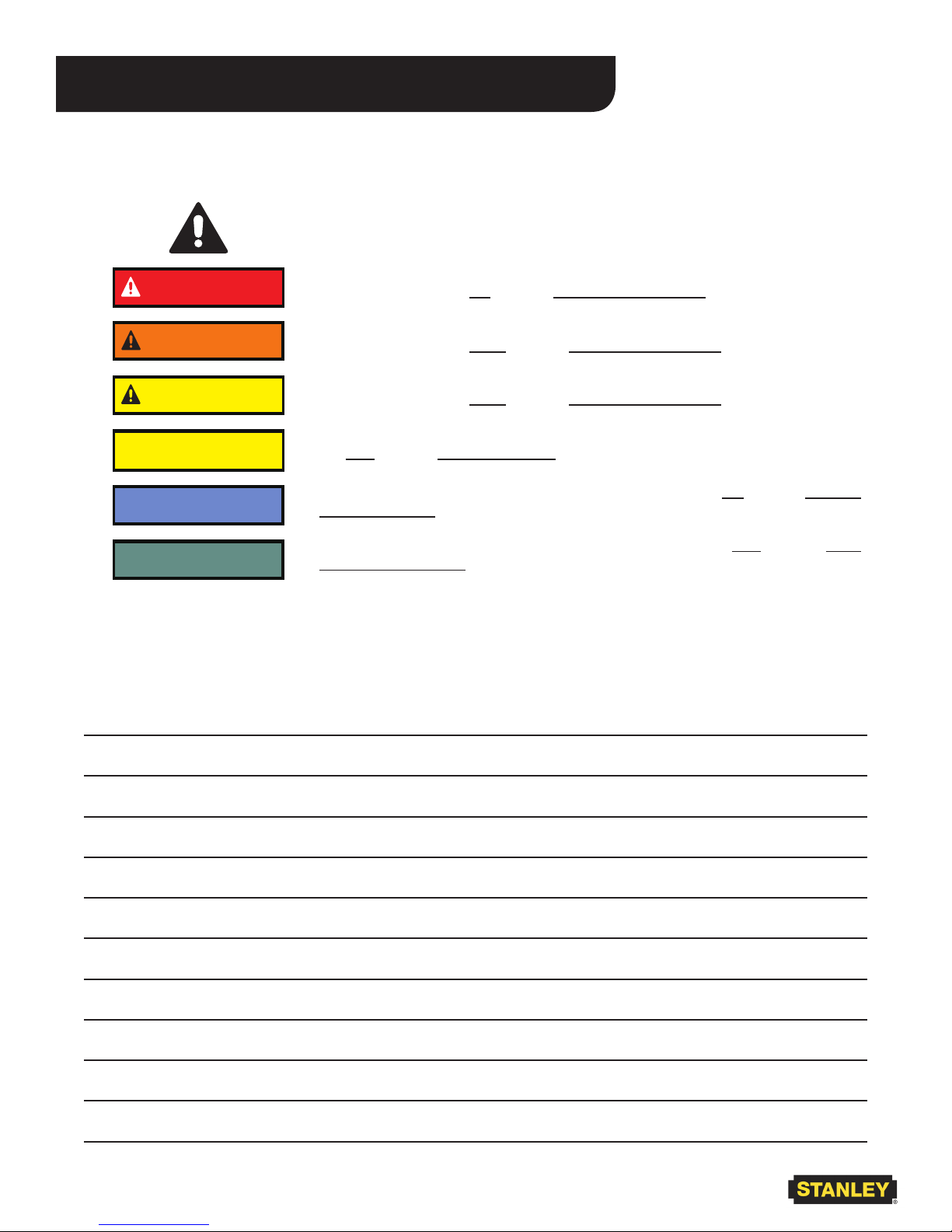
Safety symbols and signal words, as shown below, are used to emphasize all operator, maintenance and repair actions which, if not strictly followed, could result in a life-threatening situation, bodily injury or damage to equipment.
This is the safety alert symbol. It is used to alert you to potential personal injury
hazards. Obey all safety messages that follow this symbol to avoid possible
injury or death.
This safety alert and signal word indicate an imminently hazardous situation
which, if not avoided, will result in death or serious injury.
This safety alert and signal word indicate a potentially hazardous situation
which, if not avoided, could result in death or serious injury.
This safety alert and signal word indicate a potentially hazardous situation
which, if not avoided, could result in death or serious injury.
This signal word indicates a potentially hazardous situation which, if not avoided, may result in property damage.
This signal word indicates a situation which, if not avoided, will result in damage
to the equipment.
This signal word indicates a situation which, if not avoided, may result in damage to the equipment.
Always observe safety symbols. They are included for your safety and for the protection of the tool.
LOCAL SAFETY REGULATIONS
Enter any local safety regulations here. Keep these instructions in an area accessible to the operator and maintenance personnel.
4 ► CH15 User Manual
Page 5

SAFETY PRECAUTIONS
Tool operators and maintenance personnel must always
comply with the safety precautions given in this manual
and on the stickers and tags attached to the tool and
hose.
These safety precautions are given for your safety. Review them carefully before operating the tool and before
performing general maintenance or repairs.
Supervising personnel should develop additional pre-
cautions relating to the specic work area and local
safety regulations. If so, place the added precautions in
the space provided in this manual.
The CH15 Hydraulic Chipping Hammer will provide safe
and dependable service if operated in accordance with
the instructions given in this manual. Read and understand this manual and any stickers and tags attached
to the tool and hoses before operation. Failure to do so
could result in personal injury or equipment damage.
• Operator must start in a work area without bystand-
ers. The operator must be familiar with all prohibited
work areas such as excessive slopes and dangerous terrain conditions.
• Establish a training program for all operators to en-
sure safe operation.
• Do not operate the tool unless thoroughly trained or
under the supervision of an instructor.
• Always wear safety equipment such as goggles,
gloves, ear, head, and breathing protection, and
safety shoes at all times when operating the tool.
• Do not inspect, carry, clean or change the tool bit
while the hydraulic power source is connected. Accidental engagement of the tool can cause serious
injury.
• Supply hoses must have a minimum working pressure rating of 2500 psi/175 bar. Do not exceed rated
working pressure of hydraulic hose used with this
tool. Excess pressure may cause a leak or burst.
• Be sure all hose connections are tight.
• The hydraulic circuit control valve must be in the
“OFF” position when coupling or uncoupling the tool.
Wipe all couplers clean before connecting. Use only
lint-free cloths. Failure to do so may result in damage to the quick couplers and cause overheating of
the hydraulic system.
• Do not operate the tool at oil temperatures above
140 °F/60 °C. Operation at higher oil temperatures
can cause operator discomfort and may damage the
tool. Never come in contact with the tool bit, the bit
can get hot.
• Do not operate a damaged, improperly adjusted, or
incompletely assembled tool.
• Do not weld, cut with an acetylene torch, or hardface the tool bit.
• To avoid personal injury or equipment damage, all
tool repair, maintenance and service must only be
performed by authorized and properly trained personnel.
• Do not exceed the rated limits of the tool or use the
tool for applications beyond its design capacity.
• Warning: Use of this tool on certain materials during
demolition could generate dust potentially containing a variety of hazardous substances such as asbestos, silica or lead. Inhalation of dust containing
these or other hazardous substances could result
in serious injury, cancer or death. Protect yourself
and those around you. Research and understand
the materials you are cutting. Follow correct safety
procedures and comply with all applicable national,
state or provisional health and safety regulations
relating to them, including, if appropriate arranging
for the safe disposal of the materials by a qualied
person.
•
CH15 User Manual ◄ 5
Page 6

SAFETY PRECAUTIONS
• Always keep critical tool markings, such as labels
and warning stickers legible.
• Always replace parts with replacement parts recommended by Stanley Hydraulic Tools.
• Check fastener tightness often and before each use
daily.
• Never operate the tool if you cannot be sure that
underground utilities are not present.
• Do not wear loose tting clothing when operating the
tool.
• Warning: Hydraulic uid under pressure could cause
skin injection injury. If you are injured by hydraulic
uid, get medical attention immediately.
• Keep all body parts away from the working tool.
• When handling material or the tool bit, wear your
(PPE) Personal Protection Equipment.
• Be observant of the hydraulic hoses lying about the
work area, they can be a tripping hazard.
• Always de-energize the hydraulic system when
changing a tool bit.
• Take caution when changing a tool bit, tool bits can
get very hot.
• Never use the tool in an explosive atmosphere,
sparks from the breaking process could ignite explosive gas.
• Use proper lifting techniques when handling the tool,
get help from a co-worker and do not over-reach.
• Use proper protection from falling or ying debris,
keep bystanders at a safe distance.
• Do not exceed the rated ow and pressure. See
Specications in this manual for correct ow rate
and pressure rating. Rapid failure of the internal
seals may result.
• Failure to use hydraulic hose labeled and certied
as non-conductive when using hydraulic tools on or
near electric lines may result in death or serious injury.
• Handle and route hose carefully to avoid kinking,
abrasions, cutting, or contact with high temperature
surfaces. Do not use hose to pull or lift tools, power
units, etc.
• Check entire hose for cuts, cracks, leaks, abrasions,
bulges, or damage to couplings if any of these conditions exist, replace the hose immediately. Never
use tape or any device to attempt to mend the hose.
• Do not use conductive hose on or near electric lines.
This hose is not labeled or certied as non-conduc-
tive. Using this hose on or near electrical lines may
result in death or serious injury.
6 ► CH15 User Manual
Page 7

28323 CE Sticker
TOOL STICKERS & TAGS
11206 Circuit
“C” Sticker
11207 Circuit
“D” Sticker
11206 CIRCUIT “C” STICKER (5gpm)
11207 CIRCUIT “D” STICKER (8gpm)
Stanley Hydraulic Tools
3810 SE Naef Rd
Model No.
CH15
Milwaukie, Oregon 97267 U.S.A.
26-34 lpm / 7-9 gpm
140 bar / 2000 psi
33513 Name Tag Sticker (CH1553101)
36112 Name Tag Sticker (CH1532101,
CH1513101, CH1533101)
Serial Number
Stamping
66654 Sound Power Level Sticker
28409 Composite Sticker
The safety tag (P/N 15875) at right is attached to
the tool when shipped from the factory. Read and
understand the safety instructions listed on this tag
before removal. We suggest you retain this tag and
attach it to the tool when not in use.
1. FAILURE TO USE HYDRAULIC HOSE LABELED AND CERTI-
FIED AS NON-CONDUCTIVE WHEN USING HYDRAULIC
TOOLS ON OR NEAR ELECTRICAL LINES MAY RESULT IN
DEATH OR SERIOUS INJURY.
BEFORE USING HOSE LABELED AND CERTIFIED AS NON-
CONDUCTIVE ON OR NEAR ELECTRIC LINES BE SURE THE
HOSE IS MAINTAINED AS NON-CONDUCTIVE. THE HOSE
SHOULD BE REGULARLY TESTED FOR ELECTRIC CURRENT
LEAKAGE IN ACCORDANCE WITH YOUR SAFETY DEPARTMENT INSTRUCTIONS.
2. A HYDRAULIC LEAK OR BURST MAY CAUSE OIL INJECTION
INTO THE BODY OR CAUSE OTHER SEVERE PERSONAL
INJURY.
A. DO NOT EXCEED SPECIFIED FLOW AND PRESSURE
FOR THIS TOOL. EXCESS FLOW OR PRESSURE MAY
CAUSE A LEAK OR BURST.
B. DO NOT EXCEED RATED WORKING PRESSURE OF
HYDRAULIC HOSE USED WITH THIS TOOL. EXCESS
PRESSURE MAY CAUSE A LEAK OR BURST.
C. CHECK TOOL HOSE COUPLERS AND CONNECTORS
DAILY FOR LEAKS. DO NOT FEEL FOR LEAKS WITH
YOUR HANDS. CONTACT WITH A LEAK MAY RESULT
IN SEVERE PERSONAL INJURY.
IMPORTANT
READ OPERATION MANUAL AND
SAFETY INSTRUCTIONS FOR THIS
TOOL BEFORE USING IT.
USE ONLY PARTS AND REPAIR
PROCEDURES APPROVED BY
STANLEY AND DESCRIBED IN THE
OPERATION MANUAL.
TAG TO BE REMOVED ONLY BY
TOOL OPERATOR.
D. DO NOT LIFT OR CARRY TOOL BY THE HOSES. DO
NOT ABUSE HOSE. DO NOT USE KINKED, TORN OR
DAMAGED HOSE.
3. MAKE SURE HYDRAULIC HOSES ARE PROPERLY CONNECTED TO THE TOOL BEFORE PRESSURING SYSTEM.
SYSTEM PRESSURE HOSE MUST ALWAYS BE CONNECTED TO TOOL “IN” PORT. SYSTEM RETURN HOSE
MUST ALWAYS BE CONNECTED TO TOOL “OUT” PORT.
REVERSING CONNECTIONS MAY CAUSE REVERSE
TOOL OPERATION WHICH CAN RESULT IN SEVERE
PERSONAL INJURY.
4. DO NOT CONNECT OPEN-CENTER TOOLS TO CLOSEDCENTER HYDRAULIC SYSTEMS. THIS MAY RESULT IN
LOSS OF OTHER HYDRAULIC FUNCTIONS POWERED BY
THE SAME SYSTEM AND/OR SEVERE PERSONAL INJURY.
5. BYSTANDERS MAY BE INJURED IN YOUR WORK AREA.
KEEP BYSTANDERS CLEAR OF YOUR WORK AREA.
6. WEAR HEARING, EYE, FOOT, HAND AND HEAD PRO-
TECTION.
7. TO AVOID PERSONAL INJURY OR EQUIPMENT DAMAGE,
ALL TOOL REPAIR MAINTENANCE AND SERVICE MUST
ONLY BE PERFORMED BY AUTHORIZED AND PROPERLY
TRAINED PERSONNEL.
IMPORTANT
READ OPERATION MANUAL AND
SAFETY INSTRUCTIONS FOR THIS
USE ONLY PARTS AND REPAIR
PROCEDURES APPROVED BY
STANLEY AND DESCRIBED IN THE
TAG TO BE REMOVED ONLY BY
SEE OTHER SIDE
SAFETY TAG P/N 15875 (Shown smaller then actual size)
DANGERDANGER
TOOL BEFORE USING IT.
OPERATION MANUAL.
TOOL OPERATOR.
SEE OTHER SIDE
CH15 User Manual ◄ 7
Page 8

HOSE TYPES
The rated working pressure of the hydraulic hose must be equal to or higher than the relief valve setting on the hydraulic system. There are three types of hydraulic hose that meet this requirement and are authorized for use with
Stanley Hydraulic Tools. They are:
Certied non-conductive — constructed of thermoplastic or synthetic rubber inner tube, synthetic ber braid
reinforcement, and weather resistant thermoplastic or synthetic rubber cover. Hose labeled certied non-
conductive is the only hose authorized for use near electrical conductors.
Wire-braided (conductive) — constructed of synthetic rubber inner tube, single or double wire braid reinforcement, and weather resistant synthetic rubber cover. This hose is conductive and must never be used near
electrical conductors.
Fabric-braided (not certied or labeled non-conductive) — constructed of thermoplastic or synthetic rubber inner tube, synthetic ber braid reinforcement, and weather resistant thermoplastic or synthetic rubber cover. This
hose is not certied non-conductive and must never be used near electrical conductors.
HOSE SAFETY TAGS
To help ensure your safety, the following DANGER tags are attached to all hose purchased from Stanley Hydraulic
Tools. DO NOT REMOVE THESE TAGS.
If the information on a tag is illegible because of wear or damage, replace the tag immediately. A new tag may be
obtained from your Stanley Distributor.
THE TAG SHOWN BELOW IS ATTACHED TO “CERTIFIED NON-CONDUCTIVE” HOSE
DANGER
1. FAILURE TO USE HYDRAULIC HOSE LABELED AND CERTIFIED AS NON-CONDUCTIVE
WHEN USING HYDRAULIC TOOLS ON OR NEAR ELECTRIC LINES MAY RESULT IN
DEATH OR SERIOUS INJURY.
FOR PROPER AND SAFE OPERATION MAKE SURE THAT YOU HAVE BEEN PROP-
ERLY TRAINED IN CORRECT PROCEDURES REQUIRED FOR WORK ON OR AROUND
ELECTRIC LINES.
2. BEFORE USING HYDRAULIC HOSE LABELED AND CERTIFIED AS NON-CONDUCTIVE
ON OR NEAR ELECTRIC LINES. WIPE THE ENTIRE LENGTH OF THE HOSE AND FITTING WITH A CLEAN DRY ABSORBENT CLOTH TO REMOVE DIRT AND MOISTURE AND
TEST HOSE FOR MAXIMUM ALLOWABLE CURRENT LEAKAGE IN ACCORDANCE WITH
SAFETY DEPARTMENT INSTRUCTIONS.
DO NOT REMOVE THIS TAG
SEE OTHER SIDE
SIDE 1
3. DO NOT EXCEED HOSE WORKING PRESSURE OR ABUSE HOSE. IMPROPER USE
OR HANDLING OF HOSE COULD RESULT IN BURST OR OTHER HOSE FAILURE.
KEEP HOSE AS FAR AWAY AS POSSIBLE FROM BODY AND DO NOT PERMIT DIRECT
CONTACT DURING USE. CONTACT AT THE BURST CAN CAUSE BODILY INJECTION
AND SEVERE PERSONAL INJURY.
4. HANDLE AND ROUTE HOSE CAREFULLY TO AVOID KINKING, ABRASION, CUTTING, OR
CONTACT WITH HIGH TEMPERATURE SURFACES. DO NOT USE IF KINKED. DO NOT
USE HOSE TO PULL OR LIFT TOOLS, POWER UNITS, ETC.
5. CHECK ENTIRE HOSE FOR CUTS CRACKS LEAKS ABRASIONS, BULGES, OR DAMAGE TO COUPLINGS IF ANY OF THESE CONDITIONS EXIST, REPLACE THE HOSE
IMMEDIATELY. NEVER USE TAPE OR ANY DEVICE TO ATTEMPT TO MEND THE HOSE.
6. AFTER EACH USE STORE IN A CLEAN DRY AREA.
(Shown smaller than actual size)
DANGER
DANGER
SEE OTHER SIDE
SIDE 2
THE TAG SHOWN BELOW IS ATTACHED TO “CONDUCTIVE” HOSE.
DANGER
DANGER
1. DO NOT USE THIS HYDRAULIC HOSE ON OR NEAR ELECTRIC LINES. THIS HOSE IS
NOT LABELED OR CERTIFIED AS NON-CONDUCTIVE. USING THIS HOSE ON OR NEAR
ELECTRICAL LINES MAY RESULT IN DEATH OR SERIOUS INJURY.
2. FOR PROPER AND SAFE OPERATION MAKE SURE THAT YOU HAVE BEEN PROPERLY
TRAINED IN CORRECT PROCEDURES REQUIRED FOR WORK ON OR AROUND ELECTRIC LINES.
3. DO NOT EXCEED HOSE WORKING PRESSURE OR ABUSE HOSE. IMPROPER USE OR
HANDLING OF HOSE COULD RESULT IN BURST OR OTHER HOSE FAILURE. KEEP HOSE
AS FAR AWAY AS POSSIBLE FROM BODY AND DO NOT PERMIT DIRECT CONTACT
DURING USE. CONTACT AT THE BURST CAN CAUSE BODILY INJECTION AND SEVERE
PERSONAL INJURY.
4. HANDLE AND ROUTE HOSE CAREFULLY TO AVOID KINKING, CUTTING, OR CONTACT
WITH HIGH TEMPERATURE SURFACES. DO NOT USE IF KINKED. DO NOT USE HOSE TO
PULL OR LIFT TOOLS, POWER UNITS, ETC.
DO NOT REMOVE THIS TAG
SEE OTHER SIDE
SIDE 1
5. CHECK ENTIRE HOSE FOR CUTS CRACKS LEAKS ABRASIONS, BULGES, OR DAMAGE TO
COUPLINGS IF ANY OF THESE CONDITIONS EXIST, REPLACE THE HOSE IMMEDIATELY.
NEVER USE TAPE OR ANY DEVICE TO ATTEMPT TO MEND THE HOSE.
6. AFTER EACH USE STORE IN A CLEAN DRY AREA.
(Shown smaller than actual size)
DANGER
SEE OTHER SIDE
SIDE 2
DO NOT REMOVE THIS TAG
DO NOT REMOVE THIS TAG
8 ► CH15 User Manual
Page 9

Min. Working Pressure
USE
(Press/Return)
HOSE RECOMMENDATIONS
Certied Non-Conductive Hose - Fiber Braid - for Utility Bucket Trucks
Oil Flow Hose Lengths Inside Diameter
GPM LPM FEET METERS INCH MM PSI BAR
4-9 15-34 up to 10 up to 3 3/8 10 Both 2250 155
Conductive Hose - Wire Braid or Fiber Braid -DO NOT USE NEAR ELECTRICAL CONDUCTORS
4-6 15-23 up to 25 up to 7.5 3/8 10 Both 2500 175
4-6 15-23 26-100 7.5-30 1/2 13 Both 2500 175
5-10.5 19-40 up to 50 up to 15 1/2 13 Both 2500 175
5-10.5 19-40 51-100 15-30 5/8 16 Both 2500 175
5/8 16 Pressure 2500 175
3/4 19 Return 2500 175
5-10.5 19-40 100-300 30-90
10-13 38-49 up to 50 up to 15 5/8 16 Both 2500 175
5/8 16 Pressure 2500 175
3/4 19 Return 2500 175
10-13 38-49 51-100 15-30
3/4 19 Pressure 2500 175
1 25.4 Return 2500 175
10-13 38-49 100-200 30-60
5/8 16 Pressure 2500 175
3/4 19 Return 2500 175
13-16 49-60 up to 25 up to 8
3/4 19 Pressure 2500 175
1 25.4 Return 2500 175
13-16 49-60 26-100 8-30
PRESSURE
<<< FLOW
RETURN
FLOW >>>
Figure 1. Typical Hose Connections
Tool to Hydraulic Circuit Hose
Recommendations
The chart to the right shows recommended
minimum hose diameters for various hose
lengths based on gallons per minute (gpm)/
liters per minute (lpm). These recommenda-
tions are intended to keep return line pressure
(back pressure) to a minimum acceptable lev-
el to ensure maximum tool performance.
This chart is intended to be used for hydraulic
tool applications only based on Stanley Hy-
draulic Tools tool operating requirements and
should not be used for any other applications.
All hydraulic hose must have at least a rated
minimum working pressure equal to the maxi-
mum hydraulic system relief valve setting.
All hydraulic hose must meet or exceed
specications as set forth by SAE J517.
CH15 User Manual ◄ 9
Page 10

HTMA/EHTMA REQUIREMENTS
HTMA / EHTMA REQUIREMENTS
HTMA
HYDRAULIC SYSTEM REQUIREMENTS
Flow Range
Nominal Operating Pressure
(at the power supply outlet)
System relief valve setting
(at the power supply outlet)
Maximum back pressure
(at tool end of the return hose)
Measured at a max. uid viscosity of:
(at min. operating temperature)
Temperature: Sufcient heat rejection
capacity to limit max. uid temperature to:
(at max. expected ambient temperature)
Min. cooling capacity at a temperature
difference of between ambient and uid
temps
NOTE:
Do not operate the tool at oil temperatures above 140° F (60° C). Operation at higher temperatures can cause operator
discomfort at the tool.
Filter
Min. full-ow ltration
Sized for ow of at least:
(For cold temp. startup and max.
dirt-holding capacity)
4-6 gpm 7-9 gpm 9-10.5 gpm 11-13 gpm
(15-23 lpm) (26-34 lpm) (34-40 lpm) (42-49 lpm)
1500 psi 1500 psi 1500 psi 1500 psi
(103 bar) (103 bar) (103 bar) (103 bar)
2100-2250 psi 2100-2250 psi 2200-2300 psi 2100-2250 psi
(145-155 bar) (145-155 bar) (152-159 bar) (145-155 bar)
250 psi 250 psi 250 psi 250 psi
(17 bar) (17 bar) (17 bar) (17 bar)
400 ssu* 400 ssu* 400 ssu* 400 ssu*
(82 centistokes) (82 centistokes) (82 centistokes) (82 centistokes)
140° F 140° F 140° F 140° F
(60° C) (60° C) (60° C) (60° C)
3 hp 5 hp 6 hp 7 hp
(2.24 kW) (3.73 kW) (5.22 kW) (4.47 kW)
40° F 40° F 40° F 40° F
(22° C) (22° C) (22° C) (22° C)
25 microns 25 microns 25 microns 25 microns
30 gpm 30 gpm 30 gpm 30 gpm
(114 lpm) (114 lpm) (114 lpm) (114 lpm)
TYPE I TYPE II
TOOL TYPE
TYPE RR
TYPE III
Hydraulic uid Petroleum based
(premium grade, anti-wear, non-conductive)
Viscosity (at min. and max. operating temps)
NOTE:
When choosing hydraulic uid, the expected oil temperature extremes that will be experienced in service determine the
most suitable temperature viscosity characteristics. Hydraulic uids with a viscosity index over 140 will meet the requirements
over a wide range of operating temperatures.
*SSU = Saybolt Seconds Universal
EHTMA
100-400 ssu* 100-400 ssu* 100-400 ssu* 100-400 ssu*
(20-82 centistokes)
CLASSIFICATION
HYDRAULIC SYSTEM
REQUIREMENTS
Flow Range
Nominal Operating Pressure
(at the power supply outlet)
System relief valve setting
(at the power supply outlet)
NOTE: These are general hydraulic system requirements. See tool specication page for tool specic requirements
B
3.5-4.3 gpm 4.7-5.8 gpm 7.1-8.7 gpm 9.5-11.6 gpm 11.8-14.5 gpm
(13.5-16.5 lpm) (18-22 lpm) (27-33 lpm) (36-44 lpm) (45-55 lpm)
1870 psi 1500 psi 1500 psi 1500 psi 1500 psi
(129 bar) (103 bar) (103 bar) (103 bar) (103 bar)
2495 psi 2000 psi 2000 psi 2000 psi 2000 psi
(172 bar) (138 bar) (138 bar) (138 bar) (138 bar)
C
D
10 ► CH15 User Manual
Page 11

OPERATION
PREOPERATION PROCEDURES
PREPARATION FOR INITIAL USE
The tool, as shipped, has no special unpacking or assembly requirements prior to usage. Inspection to assure the tool was not damaged in shipping and does not
contain packing debris is all that is required.
CHECK HYDRAULIC POWER SOURCE
1. Using a calibrated owmeter and pressure gauge,
check that the hydraulic power source develops a
ow of 7–9 gpm/26–34 lpm at 1000–2000 psi/70–
140 bar for the 8 gpm models and 4–6 gpm at 1000–
2000 psi/70–140 bar for the 5 gpm models.
2. Make certain the hydraulic power source is equipped
with a relief valve set to open at 2100–2250 psi/145–
155 bar minimum.
3. Check that the hydraulic circuit matches the tool for
open-center (OC) operation.
CHECK TOOL
1. Make sure all tool accessories are correctly installed. Failure to install tool accessories properly
can result in damage to the tool or personal injury.
2. There should be no signs of leaks.
3. The tool should be clean, with all ttings and fasten-
ers tight.
CHECK TRIGGER MECHANISM
1. Check that the trigger operates smoothly and is free
to travel between the “ON” and “OFF” positions.
INSTALL TOOL BIT
1. Remove the solid retainer.
a. Grasp the loop of the retainer spring and pull it
from the retainer.
b. Slip the solid retainer off the chuck end.
2. Insert the tool bit into the solid retainer. The hex
shank must be toward the chuck end. Align the oval
collar with the oval slot in the chuck end of the solid
retainer.
3. Insert the tool hex shank into the chuck end to engage the hex liner. Index the shank in the hex liner to
get the desired bit orientation to the chipper.
4. Slide the solid retainer on the chuck end, aligning
the retainer spring slot with the groove.
5. Install the retainer spring.
6. Connect the hoses to the tool and the hydraulic
power source.
NOTE:
The pressure increase in uncoupled hoses left in the
sun may result in making them difcult to connect.
When possible, connect the free ends of operating
hoses together.
OPERATING PROCEDURES
1. Observe all safety precautions.
2. Move the hydraulic circuit control valve to the “ON”
position.
3. Place the tool bit rmly on the surface to be broken.
4. Squeeze the trigger to start the chipping hammer.
Adequate down pressure is very important.
NOTE:
Partially depressing the trigger allows the tool to operate at a slow speed, making it easy to start the tool
bit into the surface to be broken.
COLD WEATHER OPERATION
If the tool is to be used during cold weather, preheat the
hydraulic uid at low engine speed. When using the normally recommended uids, uid temperature should be
at or above 50 °F/10 °C (400 ssu/82 centistokes) before
use.
STORAGE
1. Disconnect the tool from the hydraulic power source.
2. Remove the tool bit and spray the chuck area with
WD-40™ inside and out.
3. Wipe clean and store in a clean, dry place.
UNDERWATER MODEL
PREVENTATIVE MAINTENANCE
After each use, the movable portions of the tool that
were exposed to water should be ushed with a water
displacing oil such as WD40. Remove any remaining
water and debris as follows:
1. Turn the tool upside down (without the tool bit) and
spray oil throughout the inside of the chuck and retainer including down inside the retainer spring, also
spray any of the exposed piston area to displace
any remaining water.
2. Spray oil into the On/Off valve trigger slot area.
3. Dip or spray the entire tool.
4. Cycle the tool hydraulically several times before
storing away.
CH15 User Manual ◄ 11
Page 12

TOOL PROTECTION & CARE
NOTICE
In addition to the Safety Precautions found in
this manual, observe the following for equipment
protection and care.
• Make sure all couplers are wiped clean before connection.
• The hydraulic circuit control valve must be in the
“OFF” position when coupling or uncoupling hydraulic tools. Failure to do so may result in damage to
the quick couplers and cause overheating of the hydraulic system.
• Always store the tool in a clean dry space, safe from
damage or pilferage.
• Make sure the circuit PRESSURE hose (with male
quick disconnect) is connected to the “IN” port. The
circuit RETURN hose (with female quick disconnect)
is connected to the opposite port. Do not reverse cir-
cuit ow. This can cause damage to internal seals.
• Always replace hoses, couplings and other parts
with replacement parts recommended by Stanley
Hydraulic Tools. Supply hoses must have a minimum working pressure rating of 2500 psi/172 bar.
• Do not exceed the rated ow and pressure. Refer
to Specications in this manual for correct ow &
pressure rate. Rapid failure of the internal seals may
result.
• Always keep critical tool markings, such as warning
stickers and tags legible.
• Do not force a small tool to do the job of a large tool.
• Keep tool bit sharp for maximum breaker perfor-
mance. Make sure that tool bits are not chipped or
rounded on the striking end.
• Never operate a chipper without a tool bit or without
holding it against the work surface. This puts excessive strain on the retainer.
• Tool repair should be performed by experienced
personnel only.
• Make certain that the recommended relief valves
are installed in the pressure side of the system.
• Do not use the tool for applications for which it was
not intended.
12 ► CH15 User Manual
Page 13

TROUBLESHOOTING
If symptoms of poor performance develop, the following chart can be used as a guide to correct the problem.
When diagnosing faults in operation of the tool, always make sure the hydraulic power source is supplying the correct hydraulic ow and pressure as listed in the table. Use a owmeter known to be accurate. Check the ow with
the hydraulic uid temperature at least 80 °F/27 °C.
PROBLEM CAUSE SOLUTION
Tool does not run. Power unit not functioning. Check power unit for proper ow and
pressure 7–9 gpm/26–34 lpm, 2000
psi/140 bar for 8 gpm model.
Check power unit for proper ow and
pressure 4–6 gpm/15–23 lpm, 2000
psi/140 bar for 5 gpm model.
Couplers or hoses blocked. Remove restriction.
Pressure and return line hoses reversed at ports.
Mechanical failure of piston or
shuttle valve.
Tool does not hit effectively. Power unit not functioning. Check power unit for proper ow and
Couplers or hose blocked. Remove restriction.
Fluid too hot Provide cooler to maintain proper uid
Incorrect tool bit . Ensure tool bit meets specications.
Tool operates slow. Low oil ow from power unit. Check power source for proper ow.
High backpressure. Check hydraulic system for excessive
Be sure hoses are connected to their
proper ports.
Have inspected and repaired by authorized dealer.
pressure 7–9 gpm/26–34 lpm, 2000
psi/140 bar for 8 gpm model.
Check power unit for proper ow and
pressure 4–6 gpm/15–23 lpm, 2000
psi/140 bar for 5 gpm model.
temperature. (Above 140 °F / 60 °C).
backpressure and correct as required.
CH15 User Manual ◄ 13
Page 14

SPECIFICATIONS
Oil Flow Range ............................................................................................................................................................
CH1553101, 5-GPM Model ........................................................................................................4-6 gpm/15-23 lpm
CH1513101, CH1533101, 8-GPM Model ...................................................................................7-9 gpm/26-34 lpm
Pressure Range................................................................................................................. 1000-2000 psi/69-140 Bar
Nominal Flow ............................................................................ 5 gpm/19 lpm or 8 gpm/30 lpm Depending on model
Length...................................................................................................................................................... 17 in./43 cm
Weight ................................................................................................................................................... 16 lb./7.25 kg
Tool Bit Models CH1513101, CH1533101, CH1553101 .............................................580 in. Hex Shank Oval Collar
Porting ...................................................................................................................................................-8 SAE O-ring
Couplers .........................................................................................HTMA/EHTMA Flush Face Type Male & Female
Connect Size and Type ...................................................................................................... 3/8 in. Male Pipe Adapter
Hose Whips ........................................................................................................................................................... Yes
Maximum Back Pressure...................................................................................................................... 250 psi/17 bar
Maximum Fluid Temperature .................................................................................................................. 140 °F/60 °C
HTMA/EHTMA Category ........................................................................................................................Type 1 and 2
Nominal Pressure ............................................................................................................................. 1500 psi/103 bar
Max Pressure ................................................................................................................................... 2000 psi/138 bar
Max Relief Pressure ......................................................................................................................... 2150 psi/148 bar
CH15 SOUND AND VIBRATION DECLARATION:
Test conducted on CH15,operated at 30 LPM input
Measured A-weighted sound power level, Lwa (ref. 1pW) in decibels 104 dBA
Uncertainty, Kwa, in decibels 1.9 dBA
Guaranteed sound power level 105 dBA
Measured A-weighted sound pressure level, Lpa (ref. 20 µPa) at operator's position, in decibels 92 dBA
Uncertainty, Kpa, in decibels 3 dBA
Values determined according to noise test code given in ISO 15744, using the basic standard
ISO3744. Test conducted by independent notied body to comply with 2000/14/EC:2005 requirements.
NOTE- The sum of a measured noise emission value and its associated uncertainty represents an upper boundary
of the range of values which is likely to occur in measurements.
Declared vibration emission value in accordance with EN 12096
Measured vibration emission value: 3-Axis (8-gpm Model) 31.9 m/sec²
Uncertainty: K 4.4 m/sec²
Measured vibration emission value: 3-Axis (5-gpm Model) 28 m/sec²
Uncertainty: K 6 m/sec²
Values determined according to ISO 8662-5, ISO 5349-1,2 (ISO 28927-10:2011)
ACCESSORIES
Description Part No.
Parker Bruning Flush Face Coupler Set, 3/8 NPT ............................................................................................. 03971
Parker Bruning Flush Face Coupler Set, 1/2 NPT ............................................................................................. 03974
Hose, 50 ft. × 1/2 in. ID, wire braid, dual, with couplers ....................................................................................31848
Hose, 25 ft. × 1/2 in. ID, wire braid, dual, with couplers ....................................................................................31972
Seal Kit ..............................................................................................................................................................35979
Point, 9 in., Oval, .580 Hex ................................................................................................................................ 66256
Narrow Chisel, 9 in., Oval, .580 Hex .................................................................................................................66257
14 ► CH15 User Manual
Page 15

CH15 PARTS ILLUSTRATION:
CH1553101 / CH1513101 / CH1533101
PARTS LIST
CH15 User Manual ◄ 15
Page 16

CH15 PARTS LIST
ITEM P/N QTY DESCRIPTION
1 — — NO ITEM
2 — — NO ITEM
3 — — NO ITEM
4 — — NO ITEM
5 07492 1 SPIROL PIN
6 28323 1 CE STICKER
7 66654 1 SOUND PWR LEVEL STICKER
8 28409 1 COMPOSITE STICKER
9 35544 1 BODY
10 00016 1 O-RING 2-015 R16*
11 33268 1 INSERT
12 31583 1 VALVE SPOOL
13 31650 1 O-RING, .176 × .040, 5 -193*
14 31597 1 VALVE SLEEVE
15 01211 5 O-RING 2-016 R16*
16 24871 4 CAPSCREW 5/16-18UNC × 3
17 62209 1 HANDLE
18 62197 1 TRIGGER ROD
19 — — NO ITEM
20 62198 1 TRIGGER
21 00878 1 DOWEL PIN, 3/16 × 1/2 SS
22 31602 1 SPIROL PIN 5/32 × 1.2
23 13815 4 CAPSCREW 5/16-18UNC × 1
24 31582 1 TRIGGER PIN
25 33513 1 NAME TAG (CH1553101)
36112 1 NAME TAG (CH1513101, CH1533101)
26 11206 1 CIRCUIT “C” DECAL (CH1553101)
11207 1 CIRCUIT “D” DECAL
(CH1513101, CH1533101)
27 31607 1 SCRAPER*
28 31606 1 CUP SEAL*
29 36111 1 CYLINDER (CH1513101, CH1533101)
35961 1 CYLINDER (CH153101)
30 07572 1 O-RING 2-135 R16*
31 33520 1 PISTON (CH1513101, CH1533101)
31590 1 PISTON (CH1553101)
32 33521 1 TUBE (CH1513101, CH1533101)
35547 1 TUBE (CH1553101)
ITEM P/N QTY DESCRIPTION
33 35546 1 DOWEL PIN, 5/32 × 1.500
34 31592 1 SHUTTLE VALVE
35 — — NO ITEM
36 65835 1 CHUCK END (CH1513101, CH1553101)
66258 1 CHUCK END (CH1533101 U/W ONLY)
37 — — NO ITEM
38 03210 1 RETAINING NOSE LINER
39 33294 1 FOAM GRIP
40 65836 1 SOLID RETAINER
41 65837 1 RETAINER SPRING
42 — — NO ITEM
43 — — NO ITEM
44 — — NO ITEM
45 35976 4 CAPSCREW 1/4 × 1.500
46 38597 1 RETAINING RING – U/W MODEL ONLY
47 01412 2 PIGTAIL HOSE ASSY 12
48 03971 1 FLUSH FACE COUPLER SET
MODEL DESIGNATIONS
CH1553101 5 GPM MODEL
CH1513101 8 GPM MODEL
CH1533101 8 GPM MODEL, UNDERWATER
SEAL KIT 35979
* DENOTES PART NUMBER IN SEAL KIT
16 ► CH15 User Manual
Page 17

Page 18

IMPORTANT
To ll out a Product Warranty Recording form, and for information on your warranty,
visit Stanleyhydraulic.com and select the Warranty tab.
(NOTE: The warranty recording form must be submitted to validate the warranty).
Stanley Hydraulic Tools
3810 SE Naef Road
Milwaukie, Oregon 97267-5698 USA
(503) 659-5660 / Fax (503) 652-1780
www.stanleyhydraulic.com
 Loading...