

Cara Glass Non Boiler
Insert Stove
PLEASE RETAIN
INSTALLATION AND OPERATING INSTRUCTIONS
This appliance is hot while in operation and retains its heat for a long period of time after use. Children,
aged or infirm persons should be supervised at all times and should not be allowed to touch the hot
working surfaces while in use or until the appliance has thoroughly cooled.
When using the stove in situations where children, aged and/or infirm persons are present a fireguard
must be used to prevent accidental contact with the stove. The fireguard should be
manufactured in accordance with BS 8423:2010.

2
TABLE OF CONTENTS
PAGE NO.
1. Stanley Solid Fuel Stove Warranty . . . . . . . . . . . . . . . . . . . . . . . . . . . . . . . . . . . . . . . . . . . . . . . . . . 3
2. Installation Checklist . . . . . . . . . . . . . . . . . . . . . . . . . . . . . . . . . . . . . . . . . . . . . . . . . . . . . . . . . . . . . 4
3. Important Operation/ Maintenance Notes . . . . . . . . . . . . . . . . . . . . . . . . . . . . . . . . . . . . . . . . . . . .5
4. Installation & Operating Instructions . . . . . . . . . . . . . . . . . . . . . . . . . . . . . . . . . . . . . . . . . . . . . . . . ..6
5. General . . . . . . . . . . . . . . . . . . . . . . . . . . . . . . . . . . . . . . . . . . . . . . . . . . . . . . . . . . . . . . . . . . . . . . ..6
6. Pre Installation Assembly . . . . . . . . . . . . . . . . . . . . . . . . . . . . . . . . . . . . . . . . . . . . . . . . . . . . . . . . . .6
7. Flues . . . . . . . . . . . . . . . . . . . . . . . . . . . . . . . . . . . . . . . . . . . . . . . . . . . . . . . . . . . . . . . . . . . . . . . . ..7
8. Chimney . . . . . . . . . . . . . . . . . . . . . . . . . . . . . . . . . . . . . . . . . . . . . . . . . . . . . . . . . . . . . . . . . . . . . . .7
9. Fitting Instructions . . . . . . . . . . . . . . . . . . . . . . . . . . . . . . . . . . . . . . . . . . . . . . . . . . . . . . . . . . . . . . .8
10. Fully Lined Chimney . . . . . . . . . . . . . . . . . . . . . . . . . . . . . . . . . . . . . . . . . . . . . . . . . . . . . . . . . . . . .8
11. Not Fully Lined Chimney . . . . . . . . . . . . . . . . . . . . . . . . . . . . . . . . . . . . . . . . . . . . . . . . . . . . . . . . . .9
12. Down Draughts . . . . . . . . . . . . . . . . . . . . . . . . . . . . . . . . . . . . . . . . . . . . . . . . . . . . . . . . . . . . . . . . .11
13. Ventilation & Combustion Air Requirements . . . . . . . . . . . . . . . . . . . . . . . . . . . . . . . . . . . . . . . . . . .12
14. Location . . . . . . . . . . . . . . . . . . . . . . . . . . . . . . . . . . . . . . . . . . . . . . . . . . . . . . . . . . . . . . . . . . . . . . . 13
15. Clearance to Combustibles . . . . . . . . . . . . . . . . . . . . . . . . . . . . . . . . . . . . . . . . . . . . . . . . . . . . . . . .13
16. Floor Protection . . . . . . . . . . . . . . . . . . . . . . . . . . . . . . . . . . . . . . . . . . . . . . . . . . . . . . . . . . . . . . . . . 14
17. Stove Dimensions . . . . . . . . . . . . . . . . . . . . . . . . . . . . . . . . . . . . . . . . . . . . . . . . . . . . . . . . . . . . . . . 14
18. Commissioning & Handover . . . . . . . . . . . . . . . . . . . . . . . . . . . . . . . . . . . . . . . . . . . . . . . . . . . . . . .15
19. Operation . . . . . . . . . . . . . . . . . . . . . . . . . . . . . . . . . . . . . . . . . . . . . . . . . . . . . . . . . . . . . . . . . . . . . . 15
20. Air Controls . . . . . . . . . . . . . . . . . . . . . . . . . . . . . . . . . . . . . . . . . . . . . . . . . . . . . . . . . . . . . . . . . . . .15
21. Recommended Fuels . . . . . . . . . . . . . . . . . . . . . . . . . . . . . . . . . . . . . . . . . . . . . . . . . . . . . . . . . . . . .15
22. Technical Data . . . . . . . . . . . . . . . . . . . . . . . . . . . . . . . . . . . . . . . . . . . . . . . . . . . . . . . . . . . . . . . . . .16
23. Lighting . . . . . . . . . . . . . . . . . . . . . . . . . . . . . . . . . . . . . . . . . . . . . . . . . . . . . . . . . . . . . . . . . . . . . . . 16
24. Lighting The Stove . . . . . . . . . . . . . . . . . . . . . . . . . . . . . . . . . . . . . . . . . . . . . . . . . . . . . . . . . . . . . . 16
25. Refuelling . . . . . . . . . . . . . . . . . . . . . . . . . . . . . . . . . . . . . . . . . . . . . . . . . . . . . . . . . . . . . . . . . . . . . 17
26. Slow Burning . . . . . . . . . . . . . . . . . . . . . . . . . . . . . . . . . . . . . . . . . . . . . . . . . . . . . . . . . . . . . . . . . . .17
27. De-Ashing . . . . . . . . . . . . . . . . . . . . . . . . . . . . . . . . . . . . . . . . . . . . . . . . . . . . . . . . . . . . . . . . . . . . . 17
28. Disposal of Ashes . . . . . . . . . . . . . . . . . . . . . . . . . . . . . . . . . . . . . . . . . . . . . . . . . . . . . . . . . . . . . . .17
29. Monthly Maintenance . . . . . . . . . . . . . . . . . . . . . . . . . . . . . . . . . . . . . . . . . . . . . . . . . . . . . . . . . . . . 18
30. Grate Removal & Cleaning . . . . . . . . . . . . . . . . . . . . . . . . . . . . . . . . . . . . . . . . . . . . . . . . . . . . . . . . 18
31. Periodic Maintenance . . . . . . . . . . . . . . . . . . . . . . . . . . . . . . . . . . . . . . . . . . . . . . . . . . . . . . . . . . . . 18
32. Chimney Cleaning . . . . . . . . . . . . . . . . . . . . . . . . . . . . . . . . . . . . . . . . . . . . . . . . . . . . . . . . . . . . . . 18
33. Glass Cleaning . . . . . . . . . . . . . . . . . . . . . . . . . . . . . . . . . . . . . . . . . . . . . . . . . . . . . . . . . . . . . . . . . 18
34. Cleaning The Outer Casing . . . . . . . . . . . . . . . . . . . . . . . . . . . . . . . . . . . . . . . . . . . . . . . . . . . . . . . 18
35. Prolonged Periods of Non Use . . . . . . . . . . . . . . . . . . . . . . . . . . . . . . . . . . . . . . . . . . . . . . . . . . . . . 19
36. Fire Safety . . . . . . . . . . . . . . . . . . . . . . . . . . . . . . . . . . . . . . . . . . . . . . . . . . . . . . . . . . . . . . . . . . . . . 19
37. Glass Replacement . . . . . . . . . . . . . . . . . . . . . . . . . . . . . . . . . . . . . . . . . . . . . . . . . . . . . . . . . . . . . . 19
38. CO Alarm . . . . . . . . . . . . . . . . . . . . . . . . . . . . . . . . . . . . . . . . . . . . . . . . . . . . . . . . . . . . . . . . . . . . . . 19
39. Exploded View . . . . . . . . . . . . . . . . . . . . . . . . . . . . . . . . . . . . . . . . . . . . . . . . . . . . . . . . . . . . . . . . ..20
STANLEY SOLID FUEL STOVE WARRANTY
CONDITIONS OF WARRANTY
Your Stanley Solid Fuel Stove is guaranteed against any part that fails (under normal operating conditions) as detailed
in the following table with timelines specified from the date of installation of the appliance. If the unit is not installed with-
in six months of date of purchase, the warranty will commence six months from the date of purchase.
Warranty Period Parts Covered (Parts & Labour unless Stated)
Up to 1 Year • Refractory materials (supply only)
• Rope seals, glass seals and cement seals.
• Surface Finish on Seno models.
• Grates and fire bars.
• Ceramic glass is covered for Thermal breakage (supply only).
• Rust (if reported before installation)
• Aesthetic Damage (provided reported on date of receipt)
Up to 5 Years • All external castings & enamel finishes (excluding impact damage or
damage caused by overfiring). Pictures of damage must be submitted to
WS Service Department.
All warranty claims must be reported to the Waterford Stanley Service Department and must be submitted with the product serial number (located on the bottom RH corner of the front plate), date of purchase, proof of purchase (if requested) and details of the specific nature of the problem.
The warranty is given only to the original consumer/purchaser only and is non- transferable. The appliance must be
installed by a suitable qualified person and installed as per the requirements of the manual. Failure to comply with the
Installation requirements or Building Regulations will void your warranty. Waterford Stanley reserve the right to replace
any part due to manufacturing defect that fails within the warranty period under the terms of the warranty. The unit must
be used for normal domestic purposes only and in accordance with manufacturer's operation instructions.
3
LIMITS OF LIABILITY
The warranty does not cover:
* Special, incidental or consequential damages, injury to persons or Property, or any other consequential loss.
* Any issue caused by negligence, misuse, abuse or circumstances beyond Waterford Stanley’s control.
* Any issue with wear and tear, modification, alteration, or servicing by anyone other than an authorized service
engineer.
* Installation and operational related problems such as draught related issues external to the stove, inadequate
venting or ventilation, excessive flue offsets, negative air pressure caused by insufficient burning of improper
fuel.
* Damage caused to the unit while in transit.
* Enamel discolouration due to over firing, enamel damage caused by impact, damage to baffles caused by
over firing and fading of surface finish on casting.
* Stress fractures on bricks.
* Rust on cast iron parts unless reported prior to unit being installed.
* Aesthetic damage, rust & missing parts on units purchased off display.
Note: Adequate clearance must be maintained around the appliance to ensure the ease of part removal in the possible event of their damage/failure. Waterford Stanley are not responsible for any costs incurred in the removal of items
installed in the vicinity of the appliance that have to be moved to facilitate a part replacement.
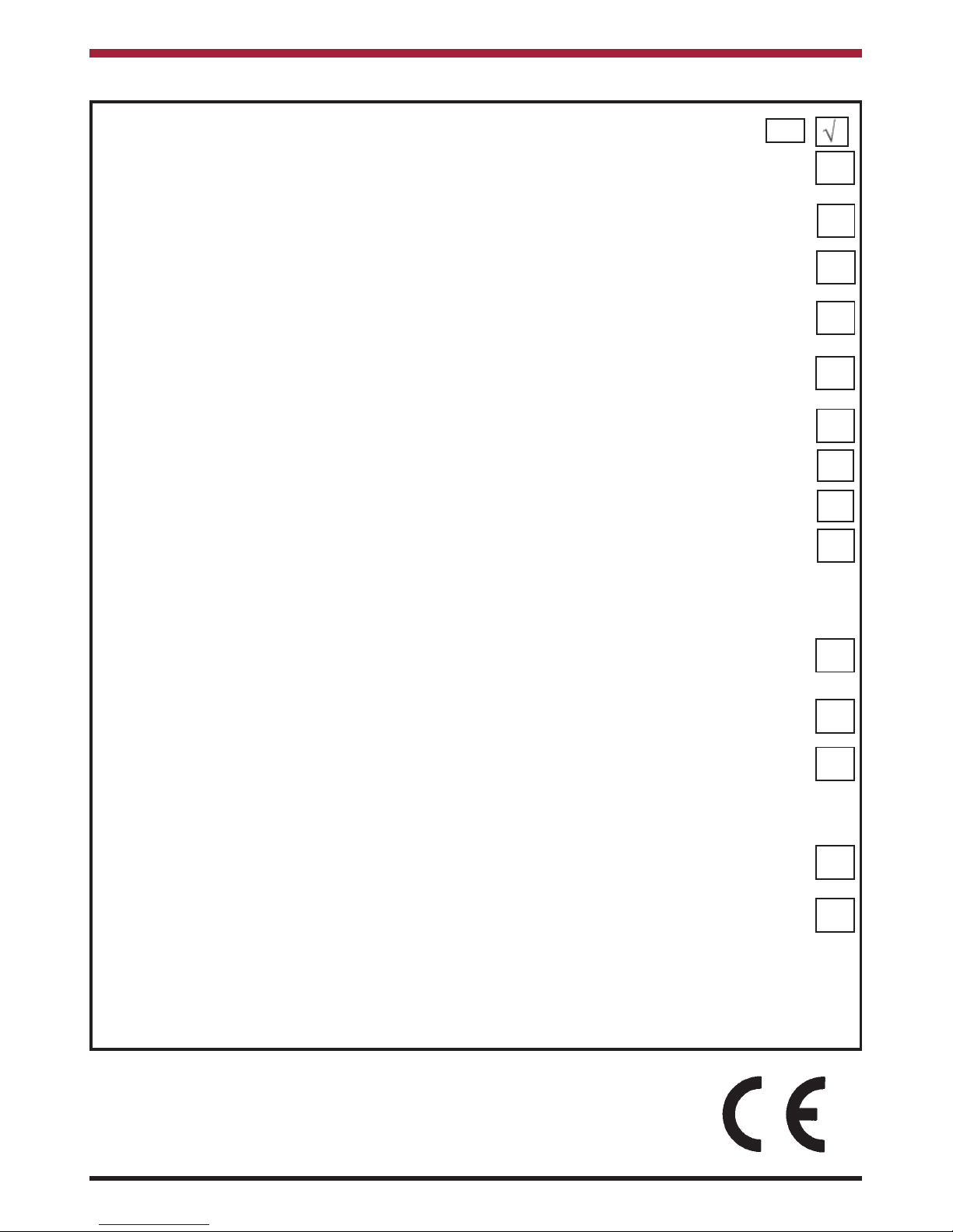
INSTALLATION CHECK LIST
Tick
Flue System
1. Minimum Flue Height of 4.6 metres (15 feet).
2. Appliance should be connected to a 125mm (5”) flue pipe within a metre and then
the flue size increased to a minimum of 150mm (6”) diameter.
3. The horizontal flue run should not exceed 150mm (6”)
4. All flue pipework passing through walls must be sleeved & adequately insulated in line
with current Building Regulations.
5. Appliance should be connected to a chimney of less than 200mm (8”) in diameter
(otherwise the chimney must be lined with a 6” flue liner).
6. The chimney/ flue termination must be located in accordance with building regulations part J.
7. The chimney serving this appliance should not serve any other appliance.
8. Access should be provided to the chimney serving the appliance to allow for cleaning.
9. It is a requirement by Building Regulations to have a carbon monoxide alarm
fitted to any room with a solid fuel appliance.
Location
10. Clearance to combustible materials must be adhered to as described in the Clearance
to Combustible section.
11. The stove must be installed on a floor protector that covers the area under the stove
and extends 14” to the front and 10” to the sides.
12. Clearance must be maintained to allow for maintenance and part replacement.
Ventilation & Combustion Air Requirements
13. The room in which the appliance is located should have an air vent of adequate
size to support correct combustion (see Ventilation & Combustion Air Requirement
Section for specific details).
14. The stove must not be installed in the same room as an extractor fan.
4
5
IMPORTANT OPERATION / MAINTENANCE NOTES
Now that your Stanley Solid Fuel Stove is installed and no doubt you are looking forward to many comforts it
will provide, we would like to give you some tips on how to get the best results from your stove.
1. We would like if you could take some time to read the operating instructions/hints, which we are
confident, will be of great benefit to you.
2. Do not burn fuel with a high moisture content, such as a damp peat or unseasoned timber. This will
only result in a build up of tar in the stove and in the chimney.
3. IMPORTANT: The first few fires should be relatively small to permit the refractory to set properly
and season the stove. During these firings it is recommended to ventilate the room as an
unpleasant (not toxic) odour may be emitted as the paint is completing curement.
4. Inspect the flue-ways of the stove weekly and ensure that there are no blockages. Check flue
ways before lighting especially after a shut down period. Please see chimney cleaning section.
5. Before loading fresh fuel into the firebox, riddle fully to remove all ashes. This will allow better and
cleaner burning. See Re-Fuelling section.
6. Never allow a build up of ashes in the ash pan, as this will cause the grate to burn out prematurely.
Empty the ashpan when refuelling.
7. Avoid slow burning of damp or unseasoned fuel as this will result in tarring flue ways and chimney i.e. peat or timber.
8. Allow adequate air ventilation to ensure plenty of air for combustion.
9. Do not burn rubbish/household plastic.
10. Clean the chimney at least twice a year.
11. Burning soft fuels such as timber and peat will stain the glass. Regular cleaning will prevent
permanent staining. Clean with soapy water when cool.
12. Keep all combustible materials a safe distance away from unit, please see section for clearances
to combustibles.
13. Never use aerosol spray near the appliance when it is in operation.
14. For safety reasons never leave children or the elderly unaccompanied while stove is in use. Use a
fire guard.
15. Avoid contact with the appliance when in use as stove reaches very high operating temperatures.
16. This appliance should be regularly maintained by a competent service engineer.
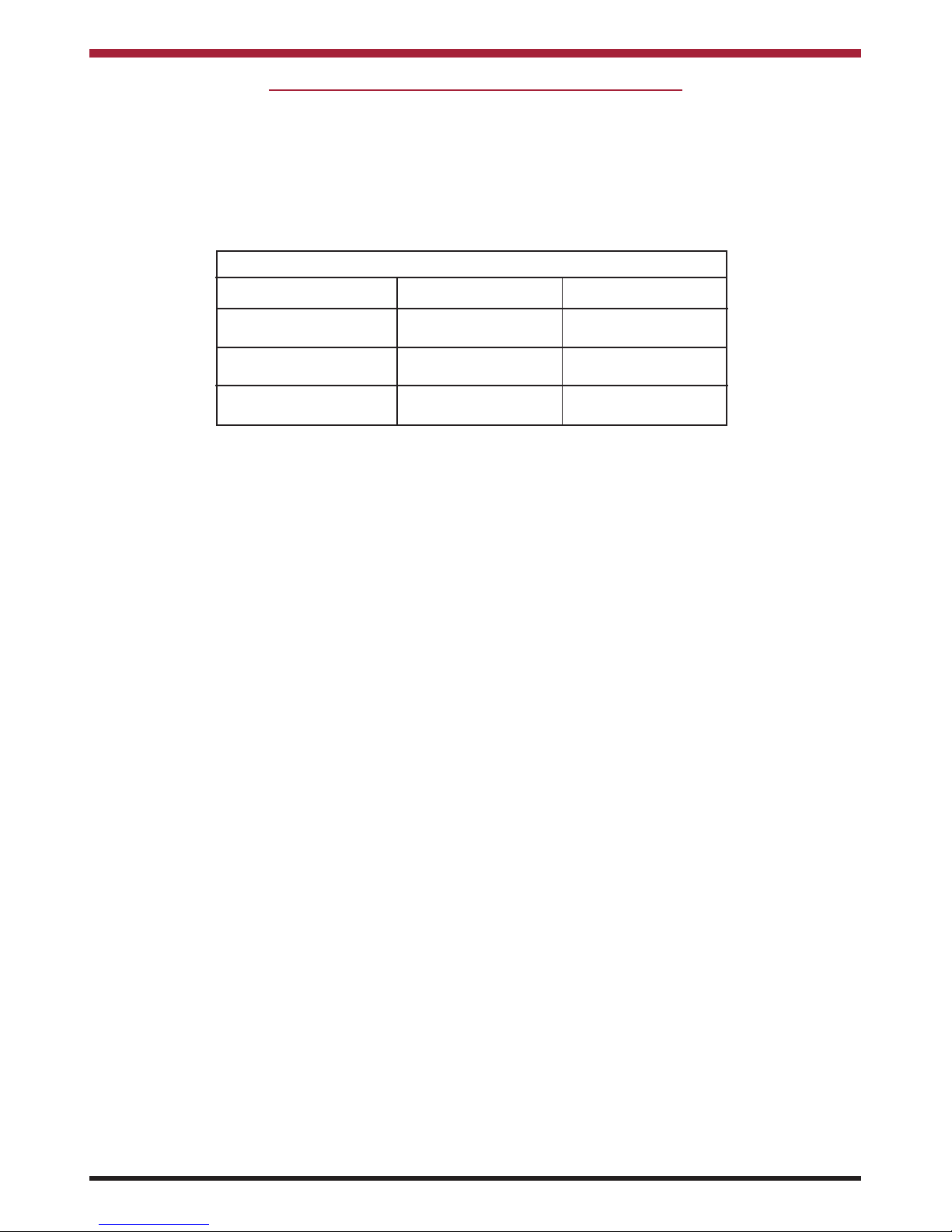
FUEL CALORIFIC VALUES - SOLID FUELS
Anthracite 25-50mm C.V.: 8.2kW/Kg 14,000 BTUs/lb
House Coal 25-75mm C.V.: 7.2kW/Kg 12,000 BTUs/lb
Timber - Firebox size C.V.: 5.0kW/Kg 8,600 BTUs/lb
Peat Briquettes C.V.: 4.8kW/Kg 8,300 BTUs/lb

6
THE CARA GLASS SOLID FUEL NON BOILER STOVE
INSTALLATION & OPERATING INSTRUCTIONS
GENERAL
When installing, operating and maintaining your
Cara Stove respect basic standards of fire safety.
Read these instructions carefully before commencing the installation. Failure to do so may result in
damage to persons and property. Consult your local
Municipal office and your insurance representative
to determine what regulations are in force. Save
these instructions for future reference.
Please note that it is a legal requirement under
England & Wales Building Regulations that the
installation of the stove is either carried out under
Local Authority Building Control approval or is
installed by a Competent Person registered with a
Government approved Competent Persons
Scheme. HETAS Ltd operate such a scheme and a
listing of their Registered Competent Persons can
be found on their website at www.hetas.co.uk.
Special care must be taken when installing the stove
such that the requirements of the Health & Safety at
Work Act are met.
Handling
Adequate facilities must be available for loading,
unloading and site handling.
Fire Cement
Some types of fire cement are caustic and should
not be allowed to come into contact with the skin. In
case of contact with the skin wash immediately with
plenty of water.
Asbestos
This stove contains no asbestos. If there is a possibility of disturbing any asbestos in the course of
installation then please seek specialist guidance and
use appropriate protective equipment.
Metal Parts
When installing or servicing this stove care should
be taken to avoid the possibility of personal injury.
“IMPORTANT WARNING”
This stove must not be installed into a chimney that
serves any other heating appliance.
The complete installation must be done in accordance with current Standards and Local Codes. It
should be noted that the requirements and these
publications may be superseded during the life of
this manual.
Please refer to the current standards, BS EN 152871:2007 Design, Installation and Commissioning of
chimneys. BS EN 14336:2004: Heating Systems in
Buildings. Installation & Commissioning of Water
Based Heating Systems. BS EN 12828: 2003;
Heating Systems in Buildings. Design of Water
Based Heating Systems. BS EN 12831: 2003;
Heating Systems in Buildings. method for
calculation of the design heat load.
PRE-INSTALLATION ASSEMBLY
After removing the stove from the packaging, open
the fire door and remove the loose packing. Prior to
installation all the internal components of the stove
are removed to gain access to fixings and to make it
lighter for installation.
Remove the refractory fire bricks, these bricks are
loose and just need to be lifted clear of the grate
support plate before they can be removed.
To remove the loose baffle, lift on right side and
move this up and to the right to give maximum clearance at the opposite side to allow the baffle be lowered clear of the supporting ledge on the left hand
side casting.
Next, remove the grate by pushing it from underneath, the riddling bar is not fixed to the grate.
The cast iron side liners must be removed prior to
the fixed baffle, to remove the side liners lift the bottom edge clear of the grate support and slide the
bottom edge towards the opposite side of the stove,
when the casting is moved to a diagonal position it
will be free to be lifted from the stove.
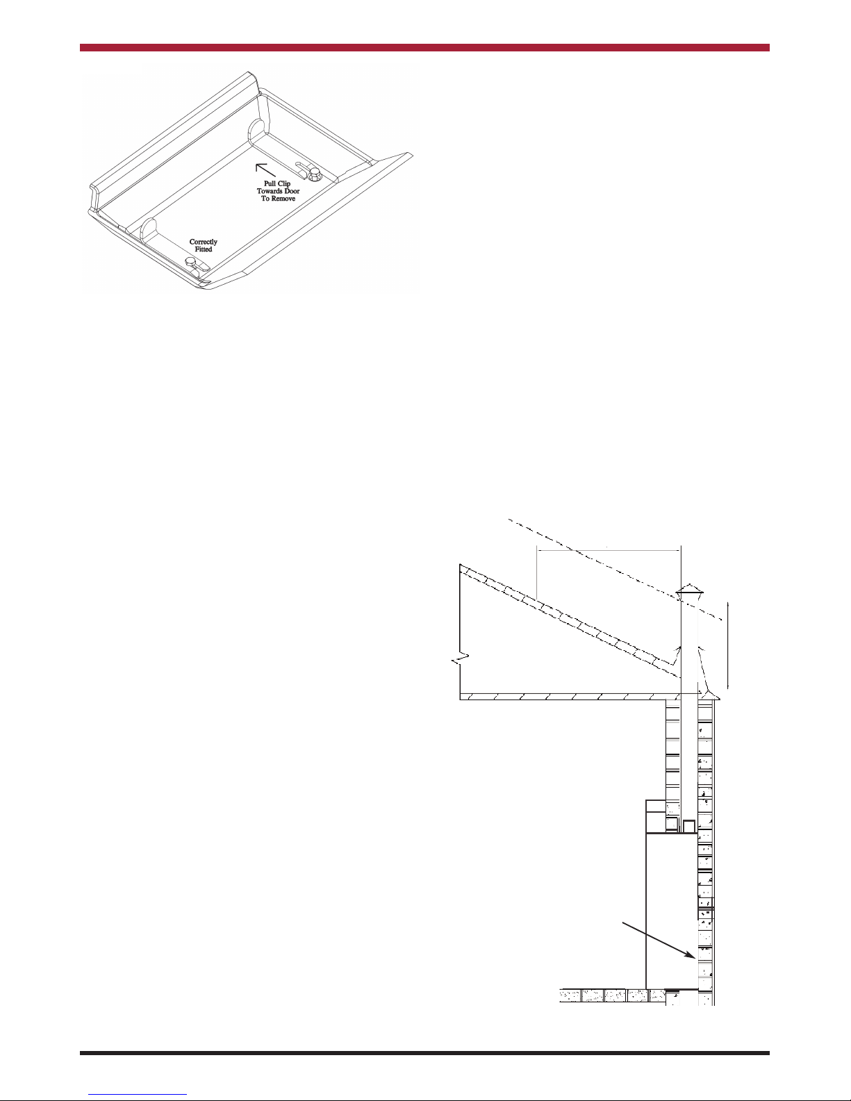
To remove the fixed baffle, loosen the two roof bolts,
support the baffle with one hand while removing the
L shaped brackets with the other hand, see Fig.1.
Your Cara Glass stove is supplied with the following
items:
• Ashpan
• Operating Tool
• Glove
• Side Bricks
• Clay Adaptor
• Rigid Pipe
•15
o
Adaptor
Do not overtighten the roof bolts when refitting the
baffle. It is adequate to leave them in a position
where the L shaped bracket has just enough room to
be removed.
Remove the flue spigot and gasket by removing the
four bolts.
To remove the insert stove from the external casing,
lift out the grate support, this will allow access to two
M6 fixings which attach the stove to the outer casing. Remove the 2 fixings, allowing the insert stove
to be removed from the external casing.
FLUES
Flues should be vertical wherever possible and
where a bend is necessary, it should not make an
angle of more than 45
o
with the vertical. Horizontal
flue runs should be avoided in order to minimise flue
resistance and to make sweeping easier it is recommended to use 2 x 45obends rather than a 90
o
bend.
CHIMNEY
Do not connect to a chimney serving another
appliance.
The stove is a radiant room heater and must be connected to a chimney of the proper size and type.
The chimney must have a cross-sectional area of at
least 30 square inches 19350sq. mm or a diameter
of at least 6” (150mm). It is best to connect to a
chimney of the same size, as connection to a larger
size may result in a somewhat less draught.
A flue that has proved to be unsatisfactory, particularly with regard to down draught should not be used
for venting this appliance until it has been examined
and any faults corrected. An existing masonry chimney should be inspected and if necessary repaired
by a competent mason or relined using an approved
lining system.
The stove must be connected to a chimney with a
minimum continuous draught of 0.06 w.g. Poor
draught conditions will result in poor performance.
All register plates, restrictor plates, damper etc.,
which could obstruct the flue at a future date should
be removed before connecting this appliance.
If connecting to an existing chimney with a flue
diameter of more that 8” it is recommend to line the
flue using a suitable stainless steel flue liner.
Where a masonry chimney is not available a proprietary type of 6”/150mm - twin wall, fully insulated
pipe may be used.
A chimney / flue termination must be located to minimise wind effects, a basic guide is that the distance
from the termination to the roof should be at be at
least 2300mm when measured horizontally and at
least 1000mm when measured vertically, (see
Fig.2). In circumstances where there are adjoining
buildings/ structures/ roof openings there are additional requirements, please refer to building regulations part J.
Fig.2
2300
1000
Fit
appliance
back into
wall
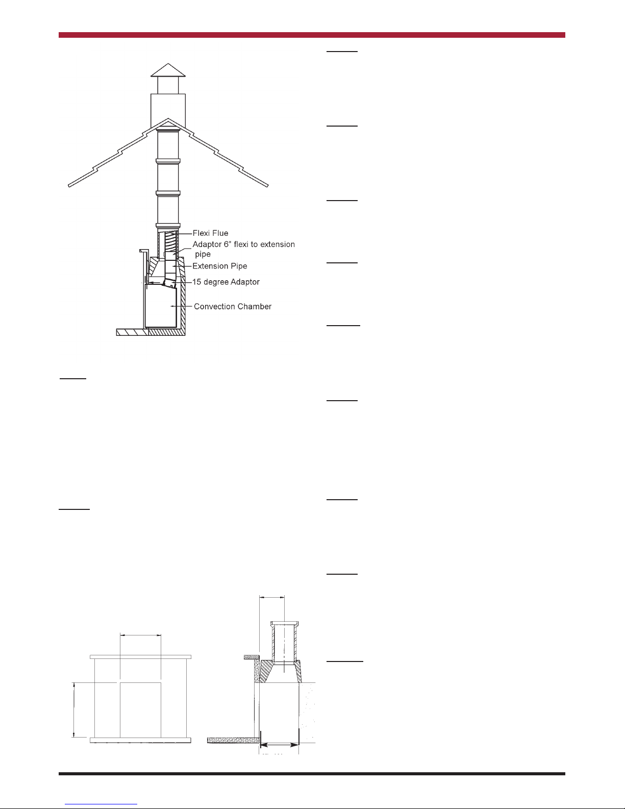
The liner should be approved for use with solid
fuel. (See Fig. 3)
Fig.1
7
8
Fig.3
405mm - 455mm
240mm - 320mm
550mm - 575mm
Min 400mm
Step 2
Ensure the floor area is level with the hearth, this
area needs to be level as the insert fire is screw
fixed to the floor. Remove all internal parts as per
pre-assembly instructions.
Step 3
Drop the flexi flue liner down through the chimney
and into the fireplace. Fit the adaptor ( not supplied
available to order) to the end of the flexible flue liner
along with the extension pipe which is supplied.
Step 4
Lay the external casing into the opening and position it so that the front plate is up against the front
edge of the opening.
Step 5
Mark the drill locations and drill the holes using a
5.5mm drill bit. Fix the casing to the floor using the
self tapping screws provided.
Step 6
Lift the stove into the casing approximately 75mm
first and then it can be pushed into the final position
while taking care to lift the front edge to preserve the
hearth.
Step 7
Lay the sealing gasket on to the flue spigot, then fit
the flue spigot to the end of the15 degree adaptor.
Fix the 15 degree adaptor to the flue spigot using the
grub screws provided. Then pass the 15 degree
adaptor through the flue opening and connect it to
the extension pipe.
Step 8
Then using the M6 x 10mm screws secure the stove
to the convection chamber. Push the insert stove
against the fireplace before fully tightening these
bolts.
Step 9
Pull the flue liner back up through the flue outlet until
the flue spigot is in position. Fix the flue spigot using
the M8 bolts provided. It may be necessary to cut a
prop to hold the spigot in place while the fixings are
being attached.
Step 10
Complete the installation of the flexi flue at the top of
the chimney in accordance with the manufacturers
instructions.
Note:
Where the product is to be installed at minimal clearances to non combustible rendered walls, it will be
necessary to have the adjacent surfaces rendered
using a heat resistant render/ plaster.
Fig.4
FITTING INSTRUCTIONS
Fully Lined Chimney
Step 1
Prepare the fireplace area with milner brick removal.
Ensure the opening is suitable for fitting of the insert
stove opening required, i.e. remove fire surround
trim if fitted. See Fig.4.
 Loading...