

Page 1
TO BE INSTALLED BY A TRAINED COMPETENT PERSON
Installation and Commissioning Instructions
This Manual is to be left with end user.
BRANDON
60K/80K/100K OIL FIRED COOKER
Page 2

TABLE OF CONTENTS
PAGE NO.
1. Introduction . . . . . . . . . . . . . . . . . . . . . . . . . . . . . . . . . . . . . . . . . . . . . . . . . . . . . . . . . . 3
2. Specification . . . . . . . . . . . . . . . . . . . . . . . . . . . . . . . . . . . . . . . . . . . . . . . . . . . . . . . . . . 4
3. Technical Data . . . . . . . . . . . . . . . . . . . . . . . . . . . . . . . . . . . . . . . . . . . . . . . . . . . . . . . . 5
4. Burner Specification . . . . . . . . . . . . . . . . . . . . . . . . . . . . . . . . . . . . . . . . . . . . . . . . . . . . 6
5. Regulations . . . . . . . . . . . . . . . . . . . . . . . . . . . . . . . . . . . . . . . . . . . . . . . . . . . . . . . . . . 7
6. Schematic . . . . . . . . . . . . . . . . . . . . . . . . . . . . . . . . . . . . . . . . . . . . . . . . . . . . . . . . . . . 7
7. Location . . . . . . . . . . . . . . . . . . . . . . . . . . . . . . . . . . . . . . . . . . . . . . . . . . . . . . . . . . . . . 8
8. Hearth Construction . . . . . . . . . . . . . . . . . . . . . . . . . . . . . . . . . . . . . . . . . . . . . . . . . . . . 8
9. Electrical Supply . . . . . . . . . . . . . . . . . . . . . . . . . . . . . . . . . . . . . . . . . . . . . . . . . . . . . . . 8
10. To Access The Control Panel . . . . . . . . . . . . . . . . . . . . . . . . . . . . . . . . . . . . . . . . . . . . . 8
11. Clearances to Combustibles . . . . . . . . . . . . . . . . . . . . . . . . . . . . . . . . . . . . . . . . . . . . . 8
12. Flue Systems . . . . . . . . . . . . . . . . . . . . . . . . . . . . . . . . . . . . . . . . . . . . . . . . . . . . . . . . . 9
13. Pre-Installation Check . . . . . . . . . . . . . . . . . . . . . . . . . . . . . . . . . . . . . . . . . . . . . . . . . . 9
14. Chimney . . . . . . . . . . . . . . . . . . . . . . . . . . . . . . . . . . . . . . . . . . . . . . . . . . . . . . . . . . . . . 9
15. Sealing . . . . . . . . . . . . . . . . . . . . . . . . . . . . . . . . . . . . . . . . . . . . . . . . . . . . . . . . . . . . . 10
16. Flue Height . . . . . . . . . . . . . . . . . . . . . . . . . . . . . . . . . . . . . . . . . . . . . . . . . . . . . . . . . . 11
17. Flue System . . . . . . . . . . . . . . . . . . . . . . . . . . . . . . . . . . . . . . . . . . . . . . . . . . . . . . . . . 11
18. Connections . . . . . . . . . . . . . . . . . . . . . . . . . . . . . . . . . . . . . . . . . . . . . . . . . . . . . . . . . . 11
19. Suitable Materials. . . . . . . . . . . . . . . . . . . . . . . . . . . . . . . . . . . . . . . . . . . . . . . . . . . . . . 11
20. Flue Cleaning . . . . . . . . . . . . . . . . . . . . . . . . . . . . . . . . . . . . . . . . . . . . . . . . . . . . . . . . . 11
21. Use of Existing Flues and Chimneys . . . . . . . . . . . . . . . . . . . . . . . . . . . . . . . . . . . . . . . 11
22. Draught Requirements . . . . . . . . . . . . . . . . . . . . . . . . . . . . . . . . . . . . . . . . . . . . . . . . . 12
23. Flue Liners . . . . . . . . . . . . . . . . . . . . . . . . . . . . . . . . . . . . . . . . . . . . . . . . . . . . . . . . . . . 12
24. Factory Made Insulated Chimneys . . . . . . . . . . . . . . . . . . . . . . . . . . . . . . . . . . . . . . . . 12
25. Ventilation & Combustion Air Requirements . . . . . . . . . . . . . . . . . . . . . . . . . . . . . . . . . 12
26. Outside Air Connection . . . . . . . . . . . . . . . . . . . . . . . . . . . . . . . . . . . . . . . . . . . . . . . . . 13
27. Heating . . . . . . . . . . . . . . . . . . . . . . . . . . . . . . . . . . . . . . . . . . . . . . . . . . . . . . . . . . . . . 13
28. Pipe Fittings . . . . . . . . . . . . . . . . . . . . . . . . . . . . . . . . . . . . . . . . . . . . . . . . . . . . . . . . . 13
29. Down Draughts . . . . . . . . . . . . . . . . . . . . . . . . . . . . . . . . . . . . . . . . . . . . . . . . . . . . . . . 14
30. Water Pipe Size . . . . . . . . . . . . . . . . . . . . . . . . . . . . . . . . . . . . . . . . . . . . . . . . . . . . . . 14
31. Draining . . . . . . . . . . . . . . . . . . . . . . . . . . . . . . . . . . . . . . . . . . . . . . . . . . . . . . . . . . . . . 15
32. Internal Pump Thermostat . . . . . . . . . . . . . . . . . . . . . . . . . . . . . . . . . . . . . . . . . . . . . . . 15
33. Water Circuit Temperature . . . . . . . . . . . . . . . . . . . . . . . . . . . . . . . . . . . . . . . . . . . . . . 15
34. Care For Your Central Heating System . . . . . . . . . . . . . . . . . . . . . . . . . . . . . . . . . . . . . 15
35. Indirect Domestic Cylinder . . . . . . . . . . . . . . . . . . . . . . . . . . . . . . . . . . . . . . . . . . . . . . . 15
36. Servicing . . . . . . . . . . . . . . . . . . . . . . . . . . . . . . . . . . . . . . . . . . . . . . . . . . . . . . . . . . . . 15
37. General Maintenance . . . . . . . . . . . . . . . . . . . . . . . . . . . . . . . . . . . . . . . . . . . . . . . . . . 15
38. Safety Valve . . . . . . . . . . . . . . . . . . . . . . . . . . . . . . . . . . . . . . . . . . . . . . . . . . . . . . . . . . 16
39. By-Pass Loop. . . . . . . . . . . . . . . . . . . . . . . . . . . . . . . . . . . . . . . . . . . . . . . . . . . . . . . . . 16
40. Open System (with pump on return) . . . . . . . . . . . . . . . . . . . . . . . . . . . . . . . . . . . . . . . 17
41. Sealed System (with pump on flow) . . . . . . . . . . . . . . . . . . . . . . . . . . . . . . . . . . . . . . . 17
42. Open System (with pump on flow). . . . . . . . . . . . . . . . . . . . . . . . . . . . . . . . . . . . . . . . . 18
43. Interlink System . . . . . . . . . . . . . . . . . . . . . . . . . . . . . . . . . . . . . . . . . . . . . . . . . . . . . . . 18
44. Provision For Filling Sealed System . . . . . . . . . . . . . . . . . . . . . . . . . . . . . . . . . . . . . . . 19
45. S Plan System . . . . . . . . . . . . . . . . . . . . . . . . . . . . . . . . . . . . . . . . . . . . . . . . . . . . . . . . 19
46. Y Plan Wiring Diagram . . . . . . . . . . . . . . . . . . . . . . . . . . . . . . . . . . . . . . . . . . . . . . . . . 19
1
Page 3

PAGE NO.
47. Wiring Diagram 100K/80K/60K . . . . . . . . . . . . . . . . . . . . . . . . . . . . . . . . . . . . . . . . . . . 20
48. S Plan Wiring Diagram Using Multi Timer . . . . . . . . . . . . . . . . . . . . . . . . . . . . . . . . . . . 21
49. S Plan Wiring Diagram Using Same Timer . . . . . . . . . . . . . . . . . . . . . . . . . . . . . . . . . . 22
50. S Plan Wiring Diagram Showing Zone Controlled By Underfloor Heating . . . . . . . . . . 23
51. Fuel Installation . . . . . . . . . . . . . . . . . . . . . . . . . . . . . . . . . . . . . . . . . . . . . . . . . . . . . . . 24
52. Oil Storage Tanks. . . . . . . . . . . . . . . . . . . . . . . . . . . . . . . . . . . . . . . . . . . . . . . . . . . . . . 24
53. Fuels . . . . . . . . . . . . . . . . . . . . . . . . . . . . . . . . . . . . . . . . . . . . . . . . . . . . . . . . . . . . . . . 24
54. Fuel Supply Line . . . . . . . . . . . . . . . . . . . . . . . . . . . . . . . . . . . . . . . . . . . . . . . . . . . . . . 24
55. Single Pipe Supply System . . . . . . . . . . . . . . . . . . . . . . . . . . . . . . . . . . . . . . . . . . . . . . 25
56. Two Pipe Supply System . . . . . . . . . . . . . . . . . . . . . . . . . . . . . . . . . . . . . . . . . . . . . . . . 25
57. Single Pipe System . . . . . . . . . . . . . . . . . . . . . . . . . . . . . . . . . . . . . . . . . . . . . . . . . . . . 25
58. Tiger Loop Oil Supply . . . . . . . . . . . . . . . . . . . . . . . . . . . . . . . . . . . . . . . . . . . . . . . . . . 25
59. Installation Check List . . . . . . . . . . . . . . . . . . . . . . . . . . . . . . . . . . . . . . . . . . . . . . . . . . 26
60. Removal of Transport Screws . . . . . . . . . . . . . . . . . . . . . . . . . . . . . . . . . . . . . . . . . . . . 28
61. Function . . . . . . . . . . . . . . . . . . . . . . . . . . . . . . . . . . . . . . . . . . . . . . . . . . . . . . . . . . . . . 28
62. Door Handle Replacement Instructions . . . . . . . . . . . . . . . . . . . . . . . . . . . . . . . . . . . . . 29
63. Installation Check List . . . . . . . . . . . . . . . . . . . . . . . . . . . . . . . . . . . . . . . . . . . . . . . . . . 31
64. Spares Parts List . . . . . . . . . . . . . . . . . . . . . . . . . . . . . . . . . . . . . . . . . . . . . . . . . . . . . . 32
65. Exploded View . . . . . . . . . . . . . . . . . . . . . . . . . . . . . . . . . . . . . . . . . . . . . . . . . . . . . . . . 33
2
Page 4

3
Introduction
Congratulations on purchasing this fine Irish made Oil-fired Central Heating Cooker. It is built to exacting
standards and it will give you every satisfaction in use.
Please read the following information before operating this excellent product.
This appliance is hot while in operation and retains its heat for a long period of time after use. Children,
aged or infirm persons should be supervised at all times and should not be allowed to touch the hot
working surfaces while in use or until the appliance has thoroughly cooled.
To ensure safety, satisfaction and reliable operation, this quality cooker should be installed by a trained and
competent person. The central heating facility and the hot water systems involved must conform fully to good
plumbing practice, established Standards/Regulations and OFTEC recommendations.
The complete installation must be done in accordance with current Standards and Local Codes. It should be
noted that the requirements and these publications may be superseded during the life of this manual.
IMPORTANT NOTICE: Any alteration to this appliance that is not approved in writing by Waterford Stanley will
render the guarantee void.
IMPORTANT — Control of Substances Harmful to Health:
It is the Users/Installers responsibility to ensure that the necessary personal protective clothing is worn when
handling materials that could be interpreted as being injurious to health and safety.
When handling Firebricks, Fire Cement or Fuels, use disposable gloves.
Exercise caution and use disposable masks and gloves when handling glues and sealants.
When working with fibre glass, mineral wool, insulation materials, ceramic blanket/board or kerosene fuel oil,
avoid inhalation as it may be harmful. Avoid contact with skin, eyes, nose and throat. Use disposable protection.
Installation should be carried out in a well ventilated area.
As manufacturers and suppliers of cooking and heating appliances, we take every possible care to ensure, as
reasonably practicable, that these appliances are so designed and constructed as to meet the general safety
requirements when properly used and installed.
* Section 10 of the Consumer Protection Act 1987.
* Safety, Health and Welfare at Work Act.
Page 5
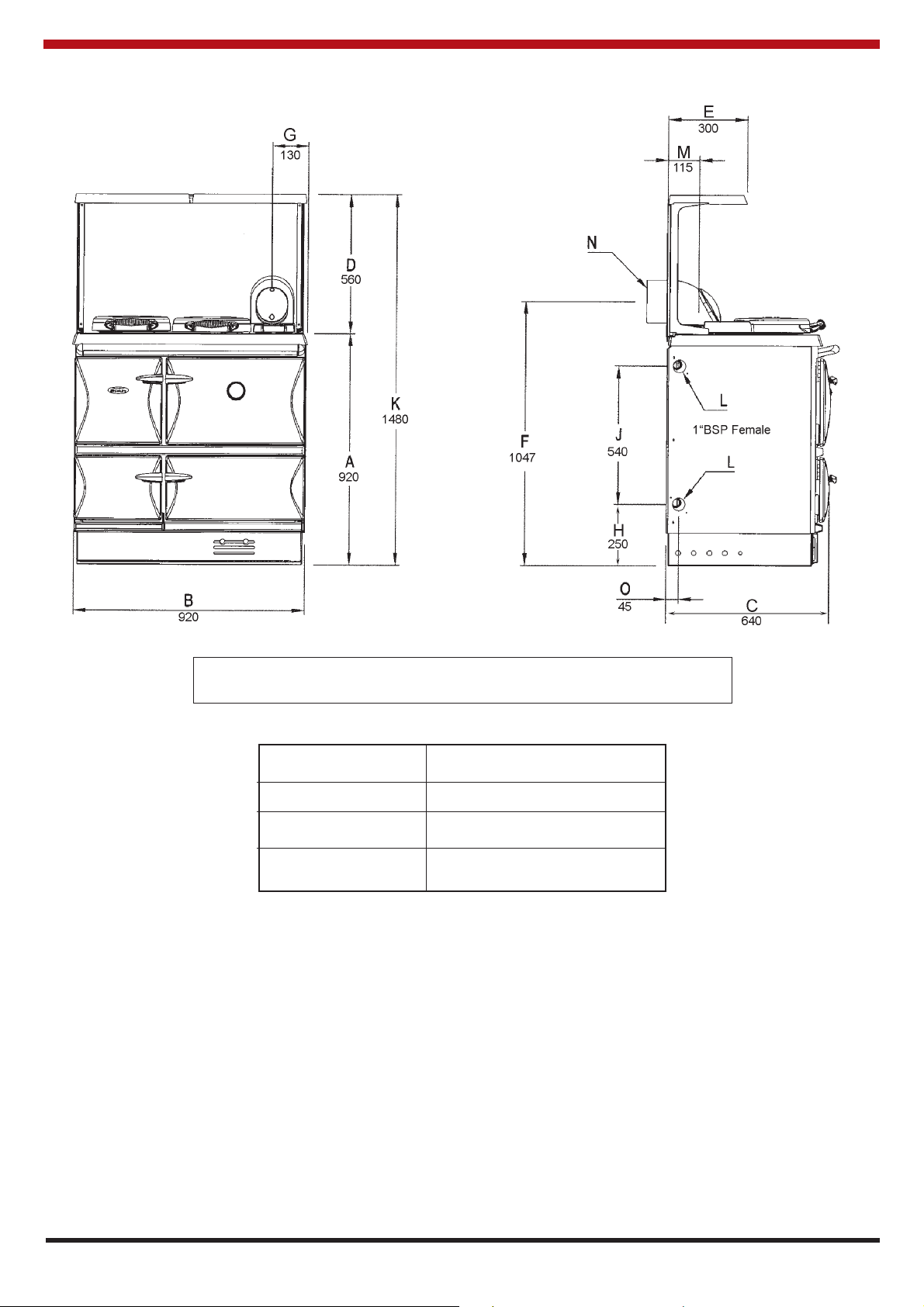
SPECIFICATION
Fig. 1
FEATURE METRIC (mm)
Hot Plate 550W x 323L
Roasting Oven 390W x 310H x 406D
Simmering Oven: 390W x 220H x 406D
Note: Dimensions stated in Fig.1 are in millimetres unless
otherwise stated and may be subject to a slight +/- variation.
4
Ø
150
Page 6

100K
BOILER OUTPUTS: 29.3kW - 100,000 Btu’s/Hr.
RADIATOR SURFACE: 53 m
2
(571 ft.2) heating surface only.
48 m
2
(514 ft.2) heating surface and domestic hot water.
FLUE GAS FLOW: Boiler: 0.005m
3
/s Oven: 0.0026m3/s.
SPACE HEATING: 2.91 kW (10,000 Btu’s/hr) cooking mode / 0.7 kW (2,500 Btu’s/hr) boiler
mode.
FLUE GAS TEMPERATURE: Boiler: 180°C (356°F) Cooker: 250°C. (482°F)
BOILER CAPACITY: 17 litres (3.74 Gal.).
BOILER MATERIAL: Mild steel.
COOKER WEIGHT: 385Kg (850 lbs).
80K
BOILER OUTPUTS: 23.45kW - 80,000 Btu’s/Hr.
RADIATOR SURFACE: 42.5 m
2
(457 ft.2) heating surface only.
37.2 m
2
(400 ft.2) heating surface and domestic hot water.
FLUE GAS FLOW: Boiler: 0.0044m
3
/s Oven: 0.0026m3/s.
SPACE HEATING: 2.91 kW (10,000 Btu’s/hr) cooking mode / 0.7 kW (2,500 Btu’s/hr) boiler
mode.
FLUE GAS TEMPERATURE: Boiler: 200°C (392°F) Cooker: 230°C. (446°F)
BOILER CAPACITY: 17 litres (3.74 Gal).
BOILER MATERIAL: Mild Steel.
COOKER WEIGHT: 380Kg (838 lbs).
60K
BOILER OUTPUTS: 17.58kW - 60,000 Btu’s/Hr.
RADIATOR SURFACE: 32 m
2
(344.45 ft.2) heating surface only.
26.5 m
2
(285 ft.2) heating surface and domestic hot water.
FLUE GAS FLOW: Boiler: 0.0031m
3
/s Oven: 0.0026m3/s.
SPACE HEATING: 2.91 kW (10,000 Btu’s/hr) cooking mode / 0.7 kW (2,500 Btu’s/hr) boiler
mode.
FLUE GAS TEMPERATURE: Boiler: 170°C (356°F) Cooker: 250°C. (482°F)
BOILER CAPACITY: 17 litres (3.74 Gal.).
BOILER MATERIAL: Mild steel.
COOKER WEIGHT: 385Kg (850 lbs).
5
FUEL: 28 Sec Kerosene
MAINS CURRENT: 230v - 240v, 50 Hz A.C.
I.P. PROTECTION: IP 20
ELECTRICAL INPUT: 90 Watts
SUPPLY FUSE RATING:3A
MAX BOILER WORKING
PRESSURE: 1.9 bar 27.3 P.S.I.
TEST PRESSURE OF
BOILER: 3 bar 43.5 P.S.I
OPERATING TEMPERATURE
LIMIT IN BOILER: 96
o
C (205oF)
TECHNICAL DATA
Page 7
THIS APPLIANCE MUST BE CONNECTED TO A FULLY PUMPED SYSTEM.
6
BURNER SPECIFICATION
BOILER BURNER COOKER BURNER
100K 80K 60K 100K/80K/60K
Burner Input
(kW) Continuous Running 34.2 27.7 21.4 19.5
(kW) Cycling N/A N/A N/A 4.4
(Btu’s) Continuous Running 116,760 94,600 73,000 66,875
(Btu’s) Cycling N/A N/A N/A 14,950
Boiler Output
(kW) Continuous Running 29.3 23.5 17.6 2.1
(kW) Mean Cycling N/A N/A N/A 1.2
(Btu’s) Continuous Running 100,000 80,000 60,000 7,000
(Btu’s) Mean Cycling N/A N/A N/A 4,000
Nozzle 0.85 80
o
S (C.E.N) 0.65 80oS (C.E.N) 0.55 80oS (C.E.N) 0.5 60oS (C.E.N)
Pressure
(Bar) 7.4 7.4 7.1 7.1
(PSI) 107 108 103 110
Fuel Consumption
(L/Hr) Continuous Running 3.6 2.9 2.2 2.1
(L/Hr) Cycling N/A N/A N/A 0.47
US Gal/Hr
Continuous Running 0.95 0.77 0.58 0.55
US Gal/Hr Cycling N/A N/A N/A 0.12
All data are taken under laboratory conditions and may vary in use
Design flow rate through the boiler 38.2 L/min / 8.4 Gpm
Static differential across the boiler 52.4 mbar / 21” wg
Dynamic pressure differential across the boiler 33 mbar / 13.23” wg
Differential Pressure Across the Boiler
Note: Design temperature differential across the boiler = 11°C (20°F)
Page 8
7
REGULATIONS
The installation must comply with the current editions of the following:
BS 5410: Oil Installations Part 1 under 45kW.
The Building Regulations: Part J England, Wales,
Part F Section 4 Scotland, Part L Northern Ireland and Part J Ireland.
The Control of Pollution (Oil) Regulations.
BS 5449: Forced circulation hot water central heating systems for domestic installations.
Health and Safety at Work Act.
BS 7671: Requirements for Electrical Regulations. Safety Document 635: The Electricity at Work
Regulations.
BS 7593: Treatment of Water in Domestic Hot Water Systems.
BS 7074 Part 1 & 2: Hot Water Supply.
BS 4814: Sealed System.
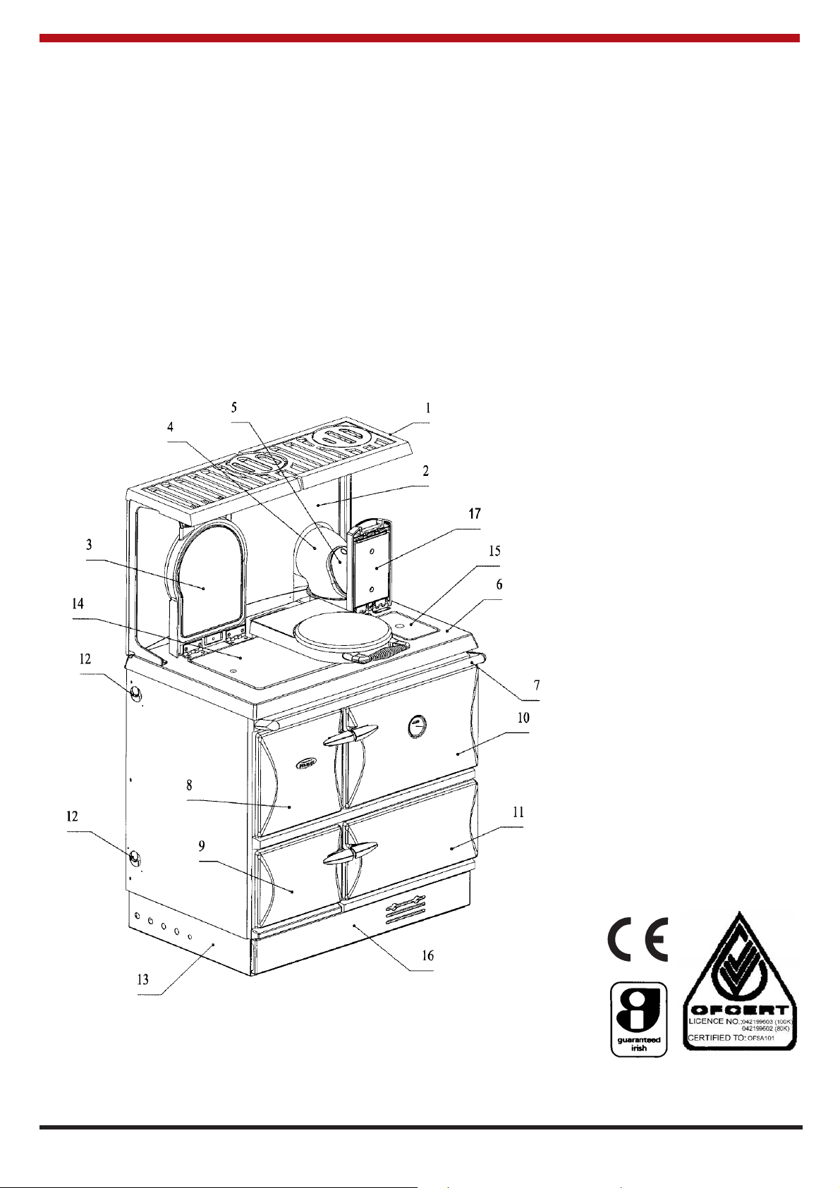
SCHEMATIC
1. Platerack (to order)
2. Splashback (to order)
3. Hotplate Covers
4. 150mm (6”) 90° Bend
5. Bend Cleaning Plate
6. Hob
7. Towel Rail
8. Firedoor
9. Burner Door
10. Main Oven Door
11. Simmer Oven Door
12. Boiler Tappings
13. Base Frame
14. Hotplate
15. Simmer and Cleaning
Plate
16. Plinth
17. Simmer Plate Cover
Fig 2.
Page 9
8
LOCATION
When choosing a location for this appliance you
must have:
(a) Sufficient room for the installation (see
clearances), a satisfactory flue (see flue
system), and an adequate air supply for correct
combustion and operation (see Ventilation and
Combustion air supply).
(b) Adequate space for maintenance and air
circulation.
(c) Solid floor or base of non-combustible material
which is capable of supporting the total weight.
(see Technical Data).
Note: Installation should be carried out in a well
ventilated area.
HEARTH CONSTRUCTION
When a non-combustible floor surface is not
available, then the cooker must be placed on other
insulating material. We recommend a slab of
precast concrete 40mm (1
1
/2
) inches deep. If other
insulating material is being used, the dimensions of
the slab of this insulating material must afford similar
protection. This hearth must extend 150mm (6
inches) to either side of the appliances and 225mm
(9 inches) to the front.
ELECTRICAL SUPPLY
All wiring external to the appliance must conform to
the current BS 7671 (U.K.), & Safety Document 635,
ETC: Part 1 Section 5.6.4. The Electricity at Work
Regulations. The cooker requires a 230V–240V, 50
Hz supply. Connection of the appliance and any
system controls to the mains supply must be
through a moulded on plug top, (which is fitted with
a 3 amp fuse) which is fitted to the appliance in
accordance with EN 60335, Consumer Protection,
SI 1994 No. 1768, plug and sockets etc. (safety)
Regulations 1994.
Always install in accordance with current local wiring
regulations.
You should always, when either exposing or working
with wiring, consult a qualified electrician.
WARNING: THIS SUPPLY MUST BE EARTHED
(Refer to B.S. 7430: Code for Practice of Earthing).
Where a risk of low voltage can occur, a voltage
sensitive device should be fitted to prevent start up
of the burner so as not to endanger the installation.
The primary fuse is located in the control box tray.
To isolate the appliance completely unplug from the
mains socket. Always ensure that this socket is
easily accessible and close to the appliance.
Persons in charge of this appliance should be aware
of this socket outlet position.
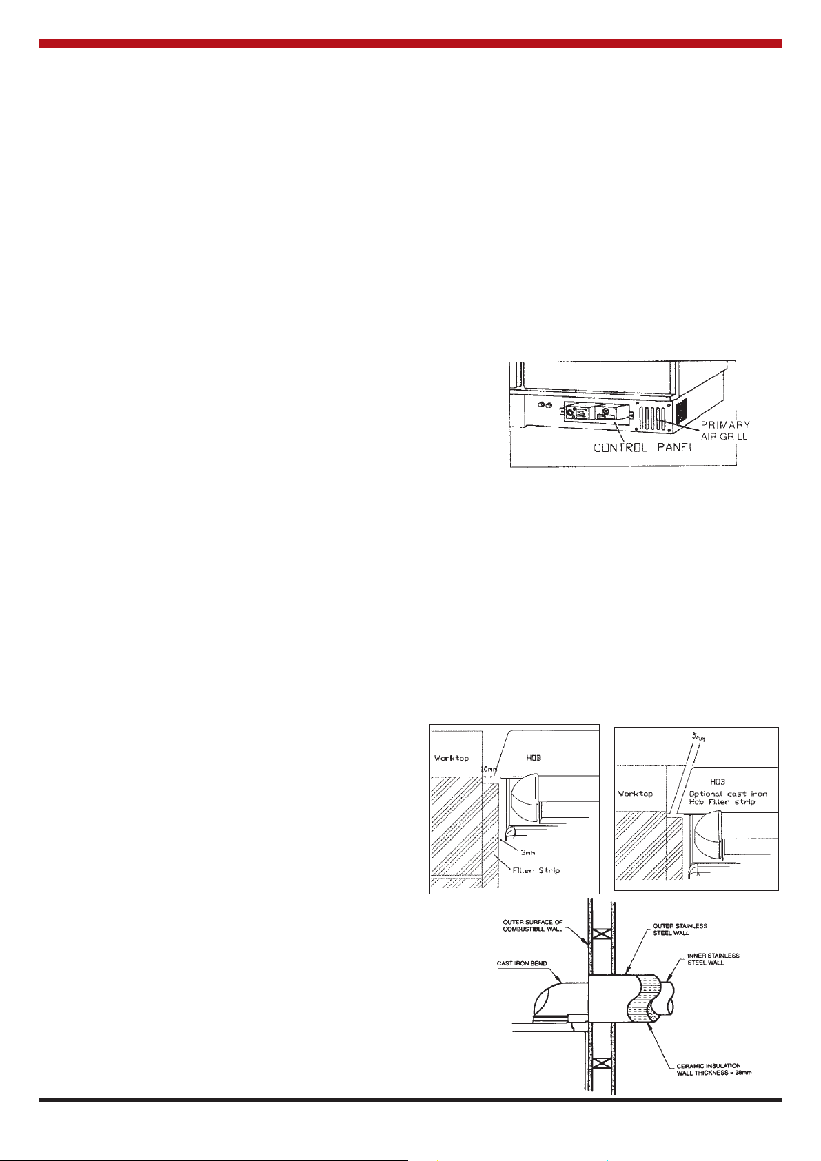
TO ACCESS THE CONTROL PANEL (See Fig.3)
a. The plinth can be removed by sliding it
approximately 20mm to the left.
b. Remove the 6 screws which hold the kicker
panel in place.
c. Remove the 2 retaining screws on either
side of the Control Consul.
d. Carefully withdraw the Control Consul, ensuring
that no strains are subjected to the wiring.
e. Connection to be carried out in accordance with
the Wiring Diagrams. (See fig’s 26 to 29
Inclusive)
Fig. 3
CLEARANCES TO COMBUSTIBLES
When bringing your kitchen units up to the sides of
the cooker leave a 10mm gap between the Stanley
and adjacent units, this gap can be reduced by
fitting an optional hob side filler strip to the Stanley
leaving a 5mm gap (see fig. 4 & 5). Likewise the
base of your units can be brought up flush to the
Stanley’s built-in plinth.
When bringing the work top up to the side of the hob
leave a 10mm gap to combustible material (see fig.
4).
Fig 4
Fig 5
Fig. 6
Page 10
9
FLUE SYSTEMS
PRE-INSTALLATION CHECK
Before installing the cooker, check that the chimney
is clean and clear of obstructions. Cracked
brickwork and leaking joints should be made good.
You must reassure yourself (with the benefit of
professional advice) that the brickwork and system
generally is of the standard suitable to support the
cooker in a safe and efficient manner.
Where flue piping passes through a closure plate
with a sliding door, ensure that the pipe continues up
and is ultimately connected to the flue liner and well
sealed with fire cement.
Do not connect to a flue serving another appliance.
Always ensure that the connection is to a chimney of
the same size - never connect to one of smaller
dimensions. Flues wholly constructed of single skin
pipe are not recommended under any
circumstances. Due to their inability to retain heat
such flues will inevitably give rise to the formation of
condensation.
IT IS NOT RECOMMENDED TO CONNECT TO A
FLUE SMALLER THAN 150mm (6”) OR IN
EXCESS OF 175mm (7”) DIAMETER.
150mm (6”) Diameter Flue Liner
Fig. 8.
Note:
Fill voids and area around liner with vermiculite or a
comparable approved material. (See Fig. 8)
Fig.7
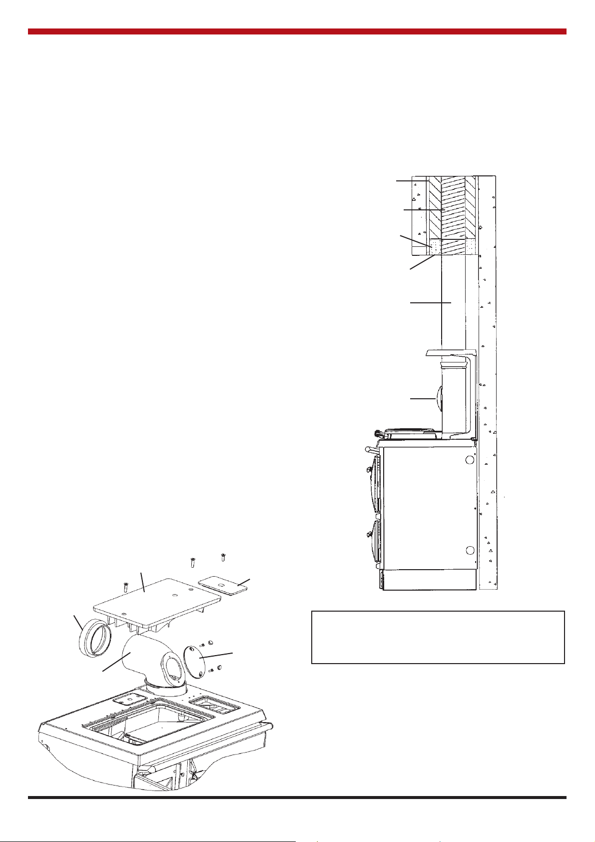
CHIMNEY
Generally the most effective chimney for oil is one
that is straight, avoid offsets and terminate with a
straight sided pot.
Where the flue passes through a combustible
material, a twin wall solid packed insulated chimney
connector must be used and must come flush with
the outer surface of the material and run all the way
to the masonry chimney or to the point of termination
of the factory made chimney. (See Fig.6)
(You should discuss the installation of your Stanley
cooker with your builder in this regard in the case of
a newly fitted kitchen.
When installing a non combustible worktop, it is
necessary to allow adequate clearance for the
removal of the hob.
Vermiculite or a
comparable material
150mm (6”)
flexible flue liner
Fire Sealing
Cement
Closure Plate
Flue Diameter of
150mm (6”)
Cleaning Plate
Simmer
Plate
Pipe Bend
Cleaning Plate
Hotplate
Flex Pipe
Adaptor
Seal Bend to
Connecting Collar
Page 11
10
Flue greater than 150mm
(6”) Diameter
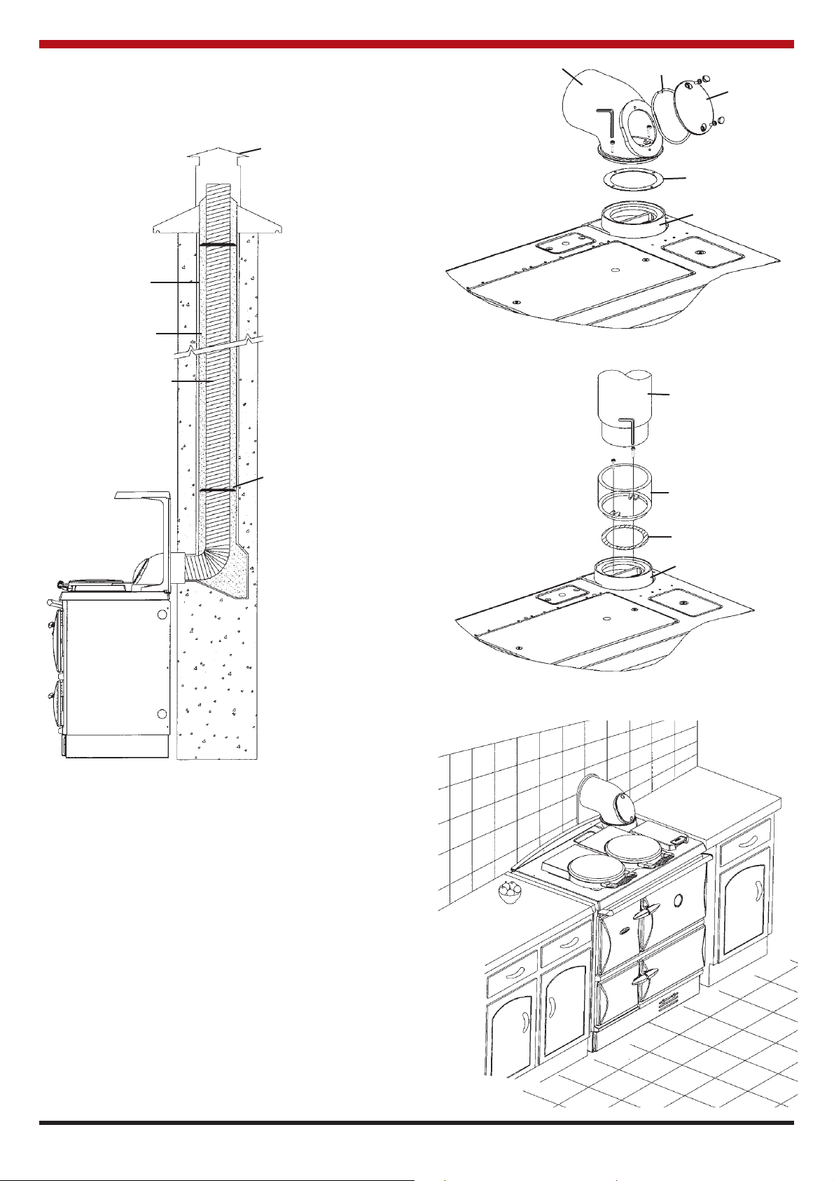
SEALING
This cooker and flue system operate under a
positive pressure. It is essential that all flue joints
are tightly sealed against flue gas leakage and
tested accordingly. (See fig. 7, 8, 9, 10 & 10a)
There is a flue pipe collar available which surrounds
the flue pipe where it meets the wall, giving a tidier
finish to a tiled background. The hob back filler piece
and flue collar rosette are available as an optional
extra. (See Fig.11)
Fig.11
Fig. 9
Fig.10
Fig.10a
Refer to Flue Assembly Instruction sheets
Approved
Flue Terminal
Bend
Gasket
Cleaning
Cover
Gasket
Collar
Pipe
Spigot
Gasket
Collar
Clay Liner
Vermiculite Filler
150mm (6”) Flexible Flue
Liner
Sealing & Clamping
Plate
Seal Flue
Connector
Page 12

FLUE HEIGHT
The flue must be high enough 4.5 mts (15ft)
minimum measured vertically from the appliance
outlet to the top of the flue terminal to allow the flue
gases to vent into the clear air, away from the
turbulence that may be caused by roof structures,
other chimney stacks, etc. The terminal position
should be in accordance with the relevant Building
Regulations.
FLUE SYSTEM
Where the standard masonry chimney is not
available, a proprietary type of non-combustible or
non-corrosive material 150mm (6”) twin wall fully
insulated pipe may be used. The pipe must
terminate at a point not lower than the main ridge or
adjacent outside obstructions. With such
installations, access to the chimney must be
provided for cleaning purposes.
Horizontal runs more than 450mm (18”) and 90°
bends numbering more than 2 per installation
should be avoided.
Fig.12
STANLEY CAST IRON PIPES AND BENDS ARE
HIGHLY RECOMMENDED FOR INTERIOR USE.
WHERE THE APPLIANCE SPIGOT OR FLUE
PIPE PROTRUDES INTO THE CHIMNEY, CARE
SHOULD BE TAKEN TO ENSURE THAT IT DOES
NOT BLOCK THE CHIMNEY.
SUITABLE MATERIALS
* Mineral Fibre cement pipes.
* Insulated metal chimneys conforming to B.S.
4543. (a galvanised finish is not suitable for
exterior use).
* Clay flue linings.
* Pre-cast concrete chimney blocks,
incorporated into the building structure. It is
particularly important that the correct
connection block be provided at the base of
the flue.
* Cast iron or acid resistant vitreous enamel
lined mild steel to B.S. 41.
* Sheet metal.
FLUE CLEANING
The flue pipe must be fitted with a cleaning plate.
The flue must be inspected annually and cleaned
when necessary.
USE OF EXISTING FLUES AND CHIMNEYS
When connecting to an existing chimney it is
necessary to line the flue using approved 150mm
(6”) rigid or flexible stainless steel flue liner.
An existing flue pipe or chimney that has proved to
be satisfactory when used for solid fuel can
normally be used for this appliance provided that its
construction, condition and dimensions are
acceptable. Flues that have proved to be
unsatisfactory, particularly with regard to down
draught, must not be considered for this appliance
until they have been examined and any faults
corrected. If there is any doubt about an existing
chimney a smoke test should be carried out.
Before connecting this appliance to a chimney or
flue pipe which has previously been used with
another fuel, the chimney or flue pipe should be
thoroughly swept and lined accordingly.
All register plates, restricter plates and dampers etc.
which could obstruct the flue at a future date should
be removed before connecting this appliance.
Where a chimney is not required to be lined a
suitable void should be provided at the base to
contain any debris which might fall from the inside
wall, so as to prevent debris from obstructing the
appliance flue outlet. (Removal of debris should be
facilitated by the provision of an access door).
If it is necessary to offset the chimney the
recommended angle is 60° to the horizontal and the
statutory minimum is 45°. (See Fig.12)
CONNECTIONS
Stanley produces the appropriate pipes and bends
used in conjunction with this cooker. Waterford
Stanley Limited will accept no liability whatsoever
ever in the event that alternative pipes and bends
are used in the installation. A cast iron 90° bend
with cleaning door is provided with the cooker. A
vertical cast iron outlet pipe with cleaning door is
also available. A flexible flue adaptor is supplied,
this is to connect the cooker 150mm (6”) bend or
straight pipe to the 150mm (6”) chimney liner.
ALL FLUE CONNECTIONS MUST BE
THOROUGHLY SEALED. Blocked chimneys are
dangerous, keep chimneys and flue ways clean,
read the operating instructions.
11
Page 13

12
This void should have a depth of not less than
250mm (10”) below the appliance connection.
The combustion products will have a descaling
effect on hardened soot deposits left from burning
solid fuels.
ALTHOUGH THE CHIMNEY MAY HAVE BEEN
CLEANED OF LOOSE SOOT PRIOR TO
INSTALLATION, IT IS IMPERATIVE THAT THE
CHIMNEY IS INSPECTED FOR SCALED SOOT
PARTICLES AFTER THE FIRST MONTH OF
OPERATION AND ANY LOOSE MATERIALS
REMOVED TO AVOID BLOCKAGE.
DRAUGHT REQUIREMENTS
While inadequate draught can seriously effect the
efficient operation of the appliance, chimney’s over
5.4m (18ft) for houses built on high ground can
experience excessive draught. A steady draught of
between 1mm (.04) and 1.5mm (.06) inches W.G. is
required for satisfactory operation.
FLUE LINERS
Chimney’s lined with salt glazed earthenware pipes
are acceptable if the pipes comply with BS EN 1457
and must be 150mm (6”). When lining an existing
chimney, a liner approved to BS 4543, Parts 1, 2 &
3 should be used. The liner should be secured at the
top and bottom by using closure/clamping plate
firmly sealed and secured and an approved low
resistance terminal used at the top.
It is essential that every flue system be inspected
and tested by a competent person for its correct
effectiveness, to ensure that the combustion
products are completely discharged to the outside
atmosphere.
FACTORY MADE INSULATED CHIMNEYS
Factory-made insulated chimneys should be
constructed and tested to meet the relevant
standards and recommendations given in:
* B.S. 7566 - Installation of factory-made
chimneys conforming to B.S. 4543 for
domestic appliances.
Part 1: Method of specifying installations
design information.
Part 2: Specification for installation design.
Part 3: Specification for site installation.
Part 4: Recommendation for installation
design and installation.
VENTILATION & COMBUSTION AIR
REQUIREMENTS
1. It is imperative that there is sufficient air supply
to the burners of the cooker in order to support
correct combustion.
2. The air supply to this appliance must comply
with BS 5410 Part 1.
3. The minimum effective air requirement for this
appliance is 215 cm
2
(100K), 193 cm2(80K) or
155cm
2
(60K). When calculating combustion air
requirements for this appliance use the following
equation: 550mm
2
per kW of maximum rated
output above 5kW. These requirements are
illustrated in OFTEC Technical Book No. 3 &
B.S. 5410.
4. If there is another appliance using air fitted in the
same or adjacent room, it will be necessary to
refer to B.S. 5410 to calculate the additional air
supply.
5. All materials used in the manufacture of air
vents should be such that the vent is
dimensionally stable and corrosion resistant.
6. The effective free area of any vent should be
ascertained before installation. The effect of
any screen or grill should be allowed for when
determining the effective free area of any vent.
7. Air vents direct to the outside of the building
should be located so that any air current
produced will not pass through normally
occupied areas of the room.
An air vent outside the building should not be
located less than the dimensions specified
within the Building Regulations (See Technical
Data) from any part of any flue terminal. These
air vents must also be satisfactorily fire proofed
as per Building Regulations.
8. Air vents in internal walls should not
communicate with bedrooms, bedsits, toilets,
bathrooms or rooms containing a shower.
9. Air vents traversing cavity walls should include a
continuous duct across the cavity. The duct
should be installed in such a manner as not to
impair the weather resistance of the cavity.
10. Joints between air vents and outside walls
should be sealed to prevent the ingress of
moisture. Existing air vents should be of the
correct size and unobstructed for the appliance
in use.
11. If there is an air extraction fan fitted in the room
or adjacent rooms where this appliance is fitted,
additional air vents will be required to aleviate
the possibility of spillage of combustion products
from the appliance/flue while the fan is in
operation. (Refer B.S. 5410).
Page 14

13
12. Where such an installation exists, a test for
spillage should be made with the fan or fans
and other burning appliances in operation at full
rate (i.e. extraction fans, tumble dryers) with all
external doors and windows closed.
13. If spillage occurs following the above operation,
an additional air vent of sufficient size to prevent
this occurrence should be installed.
OUTSIDE AIR CONNECTION
If this option is used additional air as indicated in BS
5410 is not required.
1. This appliance may be connected direct to the
outside of the house for its combustion air
supply.
2. Remove the blanking plate located at the back
right hand corner and remove the primary air
grill located at the front right hand corner. Fix
the blanking plate over the front primary air
inlet. (See fig. 14)
3. Connect the optional 125mm (5”) spigot to the
base. (See fig. 14a).
4. To connect this appliance to an outside air
supply use either 125mm (5”) rigid or flexible
stainless steel pipes or non-combustible
corrosion-resistant materials not more than
965mm (38”) in length and having no sharp
bends or corners other than the down turn at the
terminus.
5. Air inlets traversing cavity walls should include
a continuous duct across the cavity. The duct
should be installed in such a manner as not to
impair the weather resistance of the cavity.
6. Joints between air vents and outside walls
should be sealed to prevent ingress of moisture.
HEATING
PIPE FITTINGS
Materials used for insulation work should be fire
resistant. Standards should conform to all
appropriate regulations in force at the time and
place of installation.
1.1 Ferrous Materials
BS 1387 Steel tubes.
BS 1740 Steel pipe fittings.
BS 4127 Stainless steel tubes.
BS 6956 Jointing Materials.
1.2 Non-Ferrous Materials
EN 29453 Soft Solder Alloys.
BS 864 Compression tube fittings.
BS 2871 & BS EN 1057 Copper & Copper
Alloys.
Fig.14
Fig.14a
Fig.13
Air Inlet
Blanking Plate
Outside Air Spigot
(Not Supplied)
Page 15

DOWN DRAUGHTS
However well designed, constructed and positioned,
the satisfactory performance of the flue can be
adversely affected by down draught caused by
nearby hills, adjacent tall buildings or trees. These
can deflect wind to blow directly down the flue or
create a zone of high pressure over the terminal.
A suitable anti-down draught terminal or cowl will
usually effectively combat direct down blow but no
cowl is likely to prevent down blow due to high
pressure zone. Ensure that any cowl used will not
restrict the flue exit, or cause excessive back
draught. (See Fig.15)
14
Fig.15
WATER PIPE SIZE
The flow and return pipe must be 28mm diameter.
Care should be taken to ensure that the heating
system is correctly installed and that it complies with
all relevant codes of practice. If this appliance is
being connected to an existing system, we strongly
recommend that you engage an appropriately
qualified person to check the following:
(a) That the system is sound.
(b) That pipework is adequately insulated (where
applicable).
(c) Check all controls, i.e. pump, motorised valves,
time control etc. are operating satisfactorily and
are compatible with the requirements of the
cooker.
(d) Are any modifications necessary to make the
heating system more efficient?
(e) Cleanse the system and add suitable inhibitor.
The use of motorised valves, room thermostats,
radiator thermostatic valves, domestic hot water
controllers, etc, can greatly enhance a heating
system and we recommend their use.
Only competent personnel should be employed to
carry out your heating installation.
It is important that no external control devices e.g.
economisers be directly fitted to this appliance
unless covered by these installation instructions or
agreed with the manufacturer in writing. Any direct
connection of a control device not approved by the
manufacturer could make the guarantee void.
The flow and return can be taken either side of the
cooker. (See Fig.16)
1. To take off from the left simply connect directly
onto the exposed boiler connection.
2. To take off from the right side:
a. Remove the two blanks on the right hand side
of the cooker. Then remove the two cover plates
from the cooker’s back panel.
b. Remove the plugs from the boiler connections.
To avoid insulation from going into the flow and
return ports, cover with insulating tape.
c. Using copper pipe, punch out a passage way
through the insulation material to the boiler
connections. Clear any insulation away from the
boiler connections.
d. Before passing the flow and return pipes
through the cooker, cover the ends with tape to
avoid insulation entering them.
e. Remove tape from pipes and boiler ports.
Connect pipes to boiler.
Page 16

15
DRAINING
Key-operated drain taps to BS 2879 should be
provided in accessible positions in all low parts of
the system. However, it should be noted that there
may be short sections of pipework, e.g. when
passing under doorways, that may not be possible to
drain.
INTERNAL PUMP THERMOSTAT
This appliance has the capability for switching the
circulating pump ‘on’ and ‘off’ automatically. To wire
in the pump, connect the phase to terminal marked
CIRC Pump (L) and connect the Neutral to terminal
marked CIRC Pump (N). The earth wire is to be
connected into the earth block.
The connection circuit board/control panel is located
within the appliance beneath the warming oven.
(See Fig.17)
f. Replace blanking plates.
g. Plug the boiler tappings on the left hand side of
the boiler with 1” BSP plugs.
h. Test for leaks.
Fig. 16
Fig.17
WATER CIRCUIT TEMPERATURE
The return water temperature should be maintained
at not less than 50°C (122°F) so as to avoid
condensation forming within the boiler.
CARE FOR YOUR CENTRAL HEATING SYSTEM
The use of suitable corrosion inhibitors and anti
freeze solution in your heating system is essential to
minimise black oxide, sludge and scale build-up,
which effects efficiency.
In hard water areas the use of a suitable limescale
preventer / remover is advised.
Use only quantities specified by the water treatment
product manufacturer. Only add to the heating
system after flushing and finally refilling. Refer to
BS 7953.
INDIRECT DOMESTIC CYLINDER
The cooker must only be connected to an indirect
cylinder of no less than 180 litres using 28mm
diameter flow and return piping. It is recommended
that the cylinder is lagged together with pipework
with runs in excess of 4 meters (12’).
SERVICING
To ensure continued efficient and safe operation of
the appliance, it is recommended that it is checked
and serviced by an Authorised Stanley Service
Engineer at least once a year.
In the event that the cooker is not serviced by such
an engineer, at least once a year, Waterford Stanley
Limited regrets that it can entertain no claims
whatsoever in respect of alleged problems in the
efficiency or safety of the cooker supplied.
Flexible oil lines should be inspected at each
and every service visit. There are varying types
of line with guarantee periods between 1 and 5
years. It is important in the interest of safety that
flexible lines are changed at regular intervals.
Inspect for date code stamp and if the line is out
of its guarantee period or shows signs of being
kinked or damaged, replace immediately.
GENERAL MAINTENANCE
It is important that the user is familiar with their
heating system and that they ensure regular checks
and maintenance which can limit unnecessary
break-downs.
If in doubt, the user should consult an appropriately
qualified person such as a plumber or heating
engineer.
We recommend that you evaluate the overall
insulation in your house, i.e. attic, external walls,
windows and external doors. Insulation and
draught-proofing can greatly reduce running costs
Blanking Plates
50mm Knockouts RH Boiler
Connections
Page 17

16
NOTE: We strongly advise the use of pipe lagging
and also the use of a frost thermostat if the
installation is likely to be exposed to situations
where the temperature will dip to a level consistent
with frost.
A 15mm system by-pass must be fitted not less
than 1.5 meters (4.9ft) from the cooker to allow
correct water circulation for the pump and to
prevent condensation forming in the boiler. This
should be balanced. A heat sink radiator / towel rail
may be installed if desired in addition to the ByPass Loop. (See Fig.18 & Fig 24)
BY-PASS LOOP
Fig.18
Safety Valve
Pump
28mm Return
By-pass Lock
Shield Valve
28mm Flow
Pipe
1.5m
By-pass not less than 1.5
meters from the cooker
while equally enhancing living conditions. Also
zoning of areas and fitting of room thermostat can
reduce running costs, (See Fig. 18, 19, 20, 21, 22,
23, 24).
SAFETY VALVE
A non-adjustable 3 bar safety valve must be fitted to
the primary flow pipe adjacent to the boiler
connection ensuring that any discharge will not
create a hazard to occupants or cause damage to
electrical components or property.
Page 18

17
The following diagrams illustrate the different types of central heating systems to which this appliance can be
connected, but are not to be used as working drawings.
Fig. 19
OPEN SYSTEM (WITH PUMP ON RETURN)
SEALED SYSTEM (WITH PUMP ON FLOW)
Fig. 20
Page 19

18
OPEN SYSTEM (WITH PUMP ON FLOW)
Fig.21
INTERLINK SYSTEM
Fig. 22
Page 20

PROVISION FOR FILLING SEALED SYSTEM
Fig.23
19
S PLAN SYSTEM
Fig.24
COLD FEED
PIPE & OPEN
VENT PIPE
NOT MORE THAN
150mm (6”) APART
EARTH
MAINS
EARTH POST
NEUTRAL
LIVE
FLUE FAN
INTERSTAT
PUMP L
PUMP N
NEUTRAL
GREEN/YELL
WHITE
BLUE
GREY
HONEYWELL
V4073A
L641A
Cyl.Stat
T6360B
Room Stat
ORANGE
HEATING Timer
DHW Timer
NO DHW Timer
Boiler Run
Brandon
TERMINALS
WIRING
CENTRE
PERMANENT
(FUSED) LIVE
PUMP
C
2
3
1
2
Y - PLAN WIRING DIAGRAM Fig.25
Note:
It is essential that the interstat can bring on the
motorised valves directly as shown, failure to observe
this will result in nuisance lockout.
Please Note:
EARTHS NOT SHOWN FOR CLARITY
CONNECT EARTHS IN ACCORDANCE
WITH REGULATIONS!
If wires are a different colour
code, please refer to the
manufacturers instructions.
1
2
4
5
6
7
8
9
10
11
12
13
3
Page 21

20
If wires are a different colour
code, please refer to the
manufacturers instructions.
WIRING DIAGRAM 100K / 80K / 60K Fig. 26
Page 22

21
S PLAN WIRING DIAGRAM USING MULTI TIMER FOR ALL CENTRAL HEATING ZONES Fig. 27
EARTH
MAINS
EARTH POST
NEUTRAL
LIVE
FLUE FAN
INTERSTAT
PUMP L
PUMP N
NEUTRAL
HEATING Timer
DHW Timer
NO DHW Timer
Boiler Run
Brandon
TERMINALS
WIRING
CENTRE
PERMANENT
(FUSED) LIVE
BROWN
BROWN
GREY
GREY
GREY
GREY
BLUE
BLUE
GREY
BLUE
BROWN
BROWN
ORANGE
Note:
It is essential that the interstat can bring on one of the motorised valves
directly as shown, failure to observe this will result in nuisance lockout.
Please Note:
EARTHS NOT SHOWN FOR CLARITY
CONNECT EARTHS IN ACCORDANCE
WITH REGULATIONS!
BROWN
T6360B
Room Stat
T6360B
Room Stat
T6360B
Room Stat
L641A
Cyl. Stat
Motorised Valve
Domestic Hot Water
Motorised Valve
Wet Heating ZONE 1
Motorised Valve
Wet Heating ZONE 2
Motorised Valve
Wet Heating ZONE 3
If wires are a different colour
code, please refer to the
manufacturers instructions.
1
2
4
5
6
7
8
9
10
11
12
13
3
Page 23

4 ZONE HEATING SYSTEM
When connecting the a Brandon cooker to a 4 zoned heating system (i.e. separate time switches
and thermostats for domestic hot water and four
central heating zones), the domestic hot water and
one zone must be controlled directly from the
cooker enabling the inter thermostat to
operate if necessary. All other zones can
be controlled from the cooker where a
constant live supply must be connected to
the time clocks only (see figure 27).
Under no circumstances can other supply
sources be connected directly to the cooker.
4 ZONE HEATING SYSTEM
22
EARTH
EARTH POST
MAINS
NEUTRAL
LIVE
FLUE FAN
INTERSTAT
PUMP L
PUMP N
NEUTRAL
HEATING Timer
DHW Timer
NO DHW Timer
Boiler Run
Brandon
TERMINALS
WIRING
CENTRE
PERMANENT
(FUSED) LIVE
PUMP
If wires are a different colour
code, please refer to the
manufacturers instructions.
L641A
Cyl.Stat
T6360B
Room Stat
T6360B
Room Stat
T6360B
Room Stat
Motorised Valve
Domestic Hot Water
Motorised Valve
WET HEATING ZONE 1
Motorised Valve
WET HEATING ZONE 2
Motorised Valve
WET HEATING ZONE 3
c
1
2
3
2
3
2
2
3
M
M
M
M
Blue
Blue
Blue
Brown
Brown
Brown
Orange
Grey
Grey
Grey
Grey
Brown
S PLAN WIRING DIAGRAM USING SAME TIMER FOR ALL CENTRAL HEATING
ZONES Fig. 28
1
2
4
5
6
7
8
9
10
11
12
13
3
Page 24

S PLAN WIRING DIAGRAM SHOWING ZONE CONTROLLED BY UNDERFLOOR HEATING ZONE Fig.29
23
EARTH
PUMP
M
L641A
Cyl.Stat
T6360B
Room Stat
Motorised Valve WET
HEATING ZONE 1
ZONE 2 UNDERFLOOR
HEATING SYSTEM &
CONTROL
Motorised Valve
Domestic Hot Water
EARTH POST
MAINS
Brandon
TERMINALS
WIRING
CENTRE
NEUTRAL
LIVE
FLUE FAN
INTERSTAT
PUMP L
PUMP N
NEUTRAL
HEATING Timer
DHW Timer
NO DHW Timer
Boiler Run
PERMANENT
(FUSED) LIVE
M
Orange
Grey
Grey
Brown
Brown
Brown
Blue
Blue
Grey
Orange
Orange
1
2
4
5
6
7
8
9
10
11
12
13
3
Page 25

24
FUEL INSTALLATION
Jointing materials must be of types intended for use
with oil fuel. Special petroleum - resisting
compounds and PTFE tape are suitable. External
pipes should preferably be run with a continuous
rise towards the direction of flow, so that one can be
vented off. It is important to avoid high points which
could cause air locks.
Exposed lengths of oil supply pipe must be properly
supported by purpose made clips securely fixed in
place. Metal clips formed so as to hold the pipe on
to a saddle are preferred. Consideration should be
given to avoiding routes which expose the pipe to
severe chilling which could cause freezing of the oil.
Where pipes are buried, they must be protected
from accidental damage. The use of joints
underground should be avoided if at all possible. If
joints have to be fitted in pipes laid below ground,
access to them must be provided.
An oil filter (5 - 10 micron) and stop valve must be
fitted to the fuel feed line and located near the
supply tank and facilities should be provided to
enable it to be serviced without draining down the oil
supply system. (See Figs, 32, 33, 34 & 35).
At the point where the oil line enters the building, the
oil line must be fitted with an approved remote
acting fire valve, which meets the requirements of
B.S. 5410 : Part 1, fitted with the appropriate length
of capillary. The heat sensoring phial of the fire
valve must be fitted to the clip provided in the burner
compartment. It is absolutely essential that the fire
valve is located externally and is as close as
possible to the appliance. For existing installations
where the oil supply are built into the structure
internally, the remote acting fire valve should be
fitted where the oil supply line is first exposed
internally. This type of layout is not recommended
for new installations.
When gravity feed is used (the most common) the
minimum head should not be below 1 meter (3’3”)
and the maximum head should not exceed 6.5
meters (21’ 3”).
NOTE: The pump is factory set for a single pipe
installation to convert to a two pipe system consult
manufacturers instructions.
Before connecting the oil supply, secure appliance
burner oil pipes to the base using the T junction (see
Fig. 30 & 31).
OIL STORAGE TANKS
Oil storage tanks made of steel and all connecting
equipment (eg: filling pipes and vent pipes) should
comply with B.S. 799 Part 5. Galvanised steel must
not be used. Polyethylene (Plastic) tanks should
comply with OFTEC standard OFS T100 and or
equivalent. Oil should never be stored in
translucent plastic containers.
An isolating valve should be fitted at the tank outlet,
in an accessible position so that the oil supply to the
appliance can be shut off if required. This isolating
valve must be of a type suitable for use with oil.
(See Fig. 32, 33, 34 & 35).
In order to enable the sediment and water to be
removed from tanks a drain valve should be fitted.
Oil storage tank support must be carried out in
accordance with the tank manufactures
recommendations. Tanks should be located in the
most unobstructive position possible having taken
safety, filling, maintenance and the need, if any, to
provide a head of oil for the burner into
consideration.
FUELS
THE RECOMMENDED FUEL IS KEROSENE 28
SECOND VISCOSITY FUEL OIL.
FUEL SUPPLY LINE
The oil supply line from the oil storage tank to the
appliance should be of an approved and suitable
pipe with a minimum internal diameter of 9mm (3/8”)
and connected to the oil inlet connection located at
the cooker left hand side.
Oil supply pipes are normally run in annealed
copper tube complying to B.S. E.N. 1057. It can be
obtained in coil or half hard form for use with
bending machines. This pipe can also be obtained
with protective plastic sheathing applied. Fittings
for copper pipe should be compression of the flared
manipulative type to B.S. 864: Part 2 1983. Steel
pipes complying with B.S. 1387: 1985, if used, must
be protected from corrosion. Galvanised pipe and
fittings must not be used.
Screwed joints must only be made with tapered
threads complying to B.S. 1740: Part 1: 1971.
Page 26

SINGLE PIPE SUPPLY SYSTEM:
BOTTOM OF OIL STORAGE TANK ABOVE
BURNER
(See fig. 32)
Single pipe supply system: Tanks servicing this
appliance by means of a single pipe need to be
positioned so that they will apply the minimum head
required 1 meter (3’ 3”) of oil to the burner when the
fuel level is at its lowest point.
Refer to B.S. 5410 to calculate the additional head
requirement relating to pipe length and size.
TWO PIPE SUPPLY SYSTEM:
BOTTOM OF OIL STORAGE TANK BELOW OR
LEVEL WITH BURNER
(see fig. 33)
If the tank base is below the level at which the
gravity feed to the burner can be maintained, a two
pipe oil supply system may be adopted. (See fig.
33). The non-return valve in the supply line of the
two pipe system is required to prevent oil running
back from the burner and unpriming the oil pump.
The non-return valve in the return line is only
required if the top of the tank is above the burner. Its
purpose is to prevent oil running back through the
burner during maintenance.
Fig.32
Fig.30
Fig.31
SINGLE PIPE SYSTEM: WITH
DE-AERATION DEVICE BOTTOM OF OIL
STORAGE TANK BELOW OR LEVEL WITH
BURNER. (see fig. 34):
This system can be used where the tank base is
below the level at which gravity feed to the burner
can be maintained and the burner incorporates an
oil pump. The chamber is fitted close to the burner
and is linked to the tank by a single pipe, thus saving
the return pipe required by the two pipe system as
described previously. Any air in the oil brought up
from the tank is bled off in the de-aeration chamber.
De-aeration chambers must always be installed
externally to buildings because they emit small
quantities of vapour. The chamber is connected to
the oil pump in the burner of the appliance by a
normal two pipe loop.
TIGER LOOP OIL SUPPLY (see fig. 35)
For installations normally requiring a two pipe
system but have long or difficult return line runs, an
alternative Tigerloop Deaerator system can be used.
Tigerloop Deaerators remove air from a two pipe oil
feed. Higher lift heights can be achieved than are
possible with a conventional two pipe system.
These requirements are fully explained within the
following documents:
* B.S. 5410: Part 1: Code of Practice for Oil
firing installations up to 45 kW output capacity
for space heating and hot water supply
purposes.
* OFTEC - Technical Information Book Three.
Installation requirements for oil fired boiler and
oil storage tanks.
* The Building Regulations Part J: Ireland Part F
Section 4 Scotland and Part L Northern Ireland.
* The Building Regulations Part J: England &
Wales.
25
Fig.33
Page 27

26
Fig. 35
Fig. 34
INSTALLATION CHECK LIST
1. Check all items from packaging are removed
from ovens and the shelves are properly fitted.
2. Check that electrical wiring is correct.
3. Check that the boiler and heating system is full
of water and purged of air.
4. Check that the boiler plate transport screws
have been removed and that the plates are in
their correct positions. (See section removal of
transport screw and Fig. 41)
5. Time switches and room thermostats must be
on.
6. Check that all valves in the oil line are open and
that the filter is purged of air. Check that the fire
valve is open.
7. Turn on the electrical supply and check that any
time switches are on and room thermostats
associated with the cooker are on and calling for
heat. Burners should now fire.
8. Check that the interstat connection has been
wired directly to a motorised valve. This is done
by turning off room thermostats, time switches
and temporarily linking terminals 6 & 9. This
should bring on a motorised valve which will
then call the boiler.
Note: When the interstat calls; normally the
motorised valve will open, but the burner will not
operate as the supply to No.6 will be disabled.
9. Check temperature differential between flow
and return 11°C (20°F) and adjust pump or bypass accordingly.
10. Check heating circuit and balance if necessary.
11. With fuel supply off, switch on the burners.
12. Complete the start sequence to lockout (8
seconds) for both burners observing the correct
operating functions.
13. Ensure both pumps are purged of air. Check
pump pressure with a calibrated pressure gauge
and adjust it as necessary. (See Figs. 36 & 37)
For further information refer to 100K and 80K
specification on page 5.
4 Meters Max.
Page 28

27
14. Re-instate fuel supply and switch on the
burners to ensure that they fire correctly.
15. After the appliance has achieved its operating
temperature, with each burner running, carry
out a flue gas analysis for each burner. (See
Fig. 38).
16. Check for smoke and flue draught reading.
Boiler Cooker
Air CO
2
% Air CO2%
Setting Setting
9 11.5 5 10
8 11.8 4 10.34
7 11.9 3 10.8
6 12.2 2 11.2
Fig. 36
Fig.38
Fig.37
17. Check and set combustion approximate
settings:
Fig.40
Fig.39
18. Find the correct position of the air control,
which gives the highest reading of CO
2 within
the range of the table above without exceeding
a smoke No. 0-1 (Bacharach Scale). (See
Figs. 39 & 40)
19. Check the oil supply for leaks from storage
tanks via oil filter.
20. Check if complete system is working correctly.
21. Make sure specified clearances are adhered
to.
22. Check flue joints are sealed correctly and that
no escapes are present.
23. If not satisfied check the trouble shooting
guide.
Boiler Burner
flue gas test
point
Oven Burner
flue gas test
point
Page 29

28
24. After withdrawing the mains cable tighten the
anti-tug gland located at the left side of the
cooker base level.
25. Refer to the Operation Instructions Manual for
correct operation of the appliance and
familiarise the occupants on the correct
method of operating the appliance.
LEAVE ALL DOCUMENTS WITH THE END USER
26. Check lockout (8 seconds)
26a. Check cooker burner is purged of air, check
cooker burner with a calibrated pressure gauge
and adjust if necessary to 110 p.s.i.
26b. To complete commissioning exercise refer
back to point number 14.
REMOVAL OF TRANSPORT SCREW/S
Remove the hotplate and boiler top plate. Remove
retaining screws from boiler plates. Check that all
plates have remained in their correct position and
that no debris has accumulated on them during
transport. Replace boiler top plate and hotplate
ensuring that all seals are intact (See Fig.41).
FUNCTION
Normal Start
Pre-ignition and pre-purging, after 7 seconds oil
released, and the burner operates, if the flame forms
within the safety time of 10 seconds.
Post ignition after oil release:
LOA 24 - 10 seconds.
False light at start
If oil is released and no flame is established the
control will cut out within the safety time of 10
seconds.
Flame failure in operation
In the event of flame failure in operation the oil
supply is cut off and the control restarts the burner
as described under the heading “Normal Start”. On
flame failure, immediately after burner start, the
control will initiate re-ignition.
Flame monitoring
The flame is monitored by a photocell unit. Note: In
accordance with the latest ISO and DIN standards,
type LOA activates the safety relay if the photocell
unit is exposed to light in the pre-purging period.
Control of flame signal
The photocell current is measured with a d.c.
ammeter (moving coil instrument) which is
connected in series with the photocell unit. Min
current for flame indication: 35 μA.
Fig.41
NOTE: If you are in any doubt whatsoever
about the above installation checks or anything
else in this booklet, please contact Waterford
Stanley Ltd - Service Department between the
hours of 8.00am and 4.30pm Monday to Friday,
who will be happy to answer your queries.
This booklet has been prepared by Waterford
Stanley Limited to set out the correct method to
be adopted in installing a Stanley Cooker. If the
cooker is not installed fully in compliance with
these instructions, Waterford Stanley Limited
will accept no liability whatsoever for any loss,
damage or personal injury (including death)
arising out of any alleged defect in the cooker.
IMPORTANT NOTE: Once you are satisfied that
the cooker is properly installed in accordance
with these instructions, you must turn off the
cooker which should not be re-lighted until it
has been commissioned by an accredited
Commissioning Agent.
Page 30

Remove the 2 round head screws and the retaining clip on the back of the door while ensuring the spring
behind does not spring out. See Fig. A & B.
Retaining
Clip
Round Head
Screws
DOOR HANDLE REPLACEMENT INSTRUCTIONS
Fig.A
Fig.C
Fig.B
Compression Spring
Tools required
* Small Philips head screw driver
* 2 mm allen key
* Flat head screwdriver.
Remove the compression spring and screw. See Fig. C.
Round Head
Screws
Retaining
Clip
Step 1
Step 2
29
Page 31

Replace the Nylon handle with the chromed handle and reverse the above procedure - Step 5 - 1. See Fig. I
Using a small flat head screwdriver remove the circlip from the end of the door handle axle. See Fig.E & F.
Circlip
Removed
Fig.I
While holding the handle pull out the door handle axle. See Fig.G & H.
Circlip
Fig.G
Step 4
Step 5
Step 6
Grub Screw
Step 3
Fig.D
Fig.E
Fig.F
Fig.H
From the front face loosen the grub screw on the underside of the latch using the 2mm allen key. See Fig.D.
30
Page 32

31
INSTALLATION CHECK LIST
Flue System
The relevant guidelines must be adhered to for the relevant flue system A, B & C:
A. Use of an Existing Chimney
1. If connecting to an existing chimney, the appliance should be connected to a 150mm (6”) diameter
continuous, rigid or flexible flue pipe suitable for oil-fired appliances that terminates in excess of 0.6
metres from the nearest point on the roof measured vertically, and in excess of 2.3 metres measured
horizontally.
2. Minimum Flue Height of 4.6 metres (15 feet).
3. Any horizontal flue sections should not exceed 450mm (18”).
4. The chimney serving this appliance should not serve any other appliance.
5. A suitable flue terminal should be fitted at the flue termination point.
6. Closure-clamping plates should be used to seal the top & bottom of the chimney.
7. If the flue passes through a combustible wall, a twin wall insulated connector must be used and come
flush to the external surface of the wall.
8. The flue should be capable of producing a continuous draught of between 0.04” to 0.06” w.g.
B. Use of an External Flue
1. If using an external flue, the appliance should be connected to a 150mm (6”) diameter rigid insulated flue
pipe suitable for oil-fired appliances that terminates in excess of 0.6 metres from the nearest point on
the roof measured vertically and in excess of 2.3 metres measured horizontally.
2. Minimum Flue Height of 4.6 metres (15 feet).
3. Any horizontal flue sections should not exceed 450mm (18”).
4. The chimney serving this appliance should not serve any other appliance.
5. A suitable flue terminal should be fitted at the flue termination point.
6. The flue should be capable of producing a continuous draught of between 0.04” to 0.06” w.g.
C. Use of a Stanley Fan Flue
1. The flue terminal should be positioned to adhere to the minimum clearances to external obstructions as
described in the Position of Fan Flue Terminals for Oil Fired Cookers on the Brandon Fan Flue manual.
2. The exhaust point of the flue should be orientated to avoid any potential recirculation of flue gases
through the air vents.
Location
1. The cooker should be installed on a non-combustible material capable of supporting the weight of the unit.
2. The cooker should be positioned so as to maintain a 10mm gap between the cooker and the adjacent
kitchen units.
Plumbing
1. A three bar safety valve must be fitted to the primary flow pipe adjacent to the boiler connection on the
stove.
2. The cooker must be connected to a fully pumped system using 28mm flow & return supply pipes.
3. A 15mm system by-pass must be fitted not less than 1.5 metres from the cooker.
4. Hot supply to the central heating system should be controlled using a motorised valve with live supply to
valve provided by the relevant connection on the cooker control board.
Ventilation & Combustion Air Requirements
1. The room in which the appliance is located should have an air vent of adequate size to support correct
combustion when all air-using appliances are working at full capacity (See Ventilation & Combustion Air
Requirement Section for specific details).
Oil Supply
1. The oil supply tank should be fitted with an insolating valve and filter.
2. The stove should be connected to a supply line with a minimum internal diameter of 10mm (3/8”) and
must be fitted with a remote acting fire valve.
3. If a single pipe oil supply system is used, a minimum head of oil of 1 meter must be maintained (see
Fuel Installation Section).
Tick
√
Page 33

32
1. Cooker Burner - D00003BXX
2. Oil Burner Carrier Plate - Q00210AXX
3. Boiler Burner 100K - D00004BXX
Boiler Burner 80K - D00002AXX
Boiler Burner 60K - D00001AXX
4. 6” Bend - B00178AXX
5. Boiler Cleaning Door - B00187AXX
6. Hob Outer - B00192DXX
7. Flue Outlet Spigot - B00193AXX
8. Front Filler Casting - B00195AXX
9. Front - B00196CXX
10. Back Tile Trim - B00527AXX
11. Flue Cleaning Door - B00528AXX
12. Drip Tray - F00103AXX
13. Btm Cover Strip for Top Oven - F00119CXX
14. RH Side Cover Strip for Top Oven - F00120BXX
15. Control Cover Plate - F00126AXX
16. Oven Limit Stat Phial Clip - F00135AXX
17. Back Panel Blanking Plate - F00142BXX
18. Back Panel - F00154CXX
19. Side Panel RH - F00176AXX
20. Side Panel LH - F00177AXX
21. Burner Cover Plate (Oil) - F00767BXX
22. Base Edge Protectors - F00778AXX
23. Thermocouple Holder - F00785AXX
24. Insulation Panel For Oven Top - H00053AXX
25. Burner Ceramic Board - H00055BXX
26. Oven Wall Insul for Oven Firebox - H00185AXX
27. Boiler Assembly - L00076BXX
28. Hotplate Cover Assy RH - L00208AXX (B00221AXX)
29. Hotplate Cover Assy LH - L00209AXX (B00220AXX)
30. Warming Door Assy - L00361AXX (B00521AXX)
31. Control Door Assy - L00362AXX (B00522AXX)
32. Burner Door Assy - L00363AXX (B00523AXX)
33. Main Oven Door Assy - L00364AXX (B00520AXX)
34. Simmer Plate Cover Assy - L00367AXX (B00529AXX)
35. Base Assembly - L00368AXX (F00131AXX)
36. Control Panel Assembly - L00371AXX (B00525AXX)
37. Serial Number Plate - N00234BXX
38. Gasket For Simmering Plate - P00015AXX
39. Cleaning Plate Gasket - P00016AXX
40. Towel Rail Bracket Gasket - P00084AXX
41. Steam Escape - Q00107AXX
42. Shelf Diffuser - Q00126BXX
43. One Piece Oven Base - Q00168BXX
44. Warming Oven Cleaning Plate - Q00188AXX
45. Warming Oven Top - Q00189AXX
46. Simmering Plate - Q00198AXX
47. Hotplate - Q00200AXX
48. Inner Hob - Q00201CXX
49. Top Oven Bottom
- Q00202AXX
50. Oven Top - Q00203BXX
51. Oven End Flue - Q00204AXX
52. Warming Oven Flue Divider - Q00205AXX
53. LH Inner Oven Side - Q00206BXX
54. LH Oven Side - Q00207AXX
55. Oven Back - Q00208BXX
56. RH Oven Side - Q00209AXX
57. Bar Short Horizontal Side Oven - Q00212AXX
58. Boiler To Oven Clamp - Q00697BXX
59. Door Hinge - U00029AXX
60. Towel Rail Bracket LH - U00106AXX
61. Towel Rail Bracket RH - U00107AXX
62. Oven Shelf - V00092BXX
63. Door Stop - V00116AXX
64. Thermostat Bulb Spacer - V00117AXX
65. Towel Rail - V00505AXX
66. Plinth - V00506AXX
BRANDON MK3 OIL 100K/80K/60K - PARTS & BOM CODES
67. Screw Cover - V00512AXX
68. Towel Rail Bung - V00522AXX
69. Stay Rod - V00563AXX
70. Steam Vent - W00904AXX
71. Door Catch - W00918AXX
72. Flue Increaser - Q00197BXX
73. Vertical Flue Adaptor - B00184AXX
74. Hinge (Simmer Plate) - U00125AXX
75. Hob Cleaning Door Gasket - P00023AXX
76. Simmer Plate Cover Plate - F00774AXX
77. Hinge (Hotplate Assembly) - U00067AXX
78. Hotplate Cover Stop - V00083AXX
80. Bend Door Gasket - P00017AXX
81. Hotplate Cover Dome - F00183CXX
82. Hotplate Cover Handle Bracket RH - U00027AXX
83. Hotplate Cover Spring Handle - U00026AXX
84. Hotplate Cover Handle Bracket LH - U00028AXX
85. Insulation Panel - H00074AXX
86. Insulation Panel - H00073AXX
87. Insulation Panel - H00072AXX
88. Boiler Cleaning Plate - F00133AXX
89. Brandon Top Insulation Panel - H00071AXX
90. Top Boiler Baffle - L00194AXX
91. Middle Boiler Baffle - L00199AXX
92. Bottom Baffle - L00200AXX
93. Insulation Panel - H00103AXX
94. Gasket Boiler to Oven - P00026AXX
95. Boiler Blanking Plug - V00016AXX
96. Thermocouple - G00270AXX
97. Grill For Roasting Tin - V00099AXX
98. Roasting Tin - V00091AXX
99. Thermistor - G00268AXX
100. Bus Wire - G00269AXX
101. Round Hotplate Cover Filler RH - Q00617AXX
102. Round Hotplate Cover FIller LH - Q00616AXX
103. Burner PCB Board - G00266AXX
104. Wiring ID Label - N00359AXX
105. Control Box Bracket -F00780AXX
106. Oven Limit Stat - G00018AXX
107. Limit Stat - G00267AXX
108. Boiler Stat Plate - F00370AXX
109. Grommet - V00155AXX
110. Divider Plate - F00128AXX
111. Control Box Cover - F00812BXX
112. Grommet - V00100AXX
113. Air Inlet Blanking Plate - F00775AXX
114. Spacer - F00141AXX
115. Oven Door Panel - F00765AXX
116. Warming Oven Panel - F00151AXX
117. Door Handle RH - U00105BXX
118. Door Handle LH
- U00104BXX
119. Door Handle Axle - V00105AXX
120. Door Latch - V00504BXX
121. Door Handle Bracket LH - V00103AXX
122. Door Handle Bracket RH - V00104AXX
123. Door Handle Insulation - J00127AXX
124. Thermometer - G00261AXX
126. Burner Door Panel - F00150AXX
127. Fire Door Panel - F00764AXX
128. Door Latch Adjuster - F00808BXX
129. Spring - V00564AXX
130. Setting & Op Controller Label - N00331BXX
131. Control Panel Glass - T00038AXX
132. Timer Unit PCB Board - G00264AXX
Page 34

33
BRANDON OIL MK3 EXPLODED VIEW
Page 35

34
Page 36

N00334AXX DP100421 Rev 007
Manufactured by
Waterford Stanley Ltd.,
Unit 210, IDA Industrial Estate, Cork Road,
Waterford, Ireland.
Tel: (051) 302300 Fax (051) 302315
www.waterfordstanley.com
35
 Loading...