

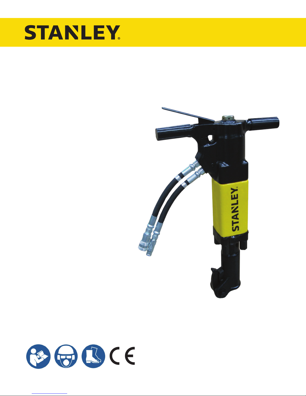
BR87
HYDRAULIC BREAKER
USER MANUAL
Safety, Operation and Maintenance
© 2014 STANLEY Black & Decker, Inc.
New Britain, CT 06053
U.S.A.
65778 9/2018 Ver. 26
DECLARATION OF CONFORMITY
Nuerenberg, David
(For Underwater Use Only)
Directive/Standards
No.
Approved body
ISO
28927-10
Self
DECLARATION OF CONFORMITY
ÜBEREINSTIMMUNGS-ERKLARUNG
DECLARATION DE CONFORMITE CEE
DECLARACION DE CONFORMIDAD
DICHIARAZIONE DI CONFORMITA
______________________________________________________________________
I, the undersigned:
Ich, der Unterzeichnende:
Je soussigné:
El abajo firmante:
lo sottoscritto:
hereby declare that the equipment specified hereunder:
bestätige hiermit, daß erklaren Produkt genannten Werk oder Gerät:
déclare que l’équipement visé ci-dessous:
Por la presente declaro que el equipo se especifica a continuación:
Dichiaro che le apparecchiature specificate di seguito:
Surname and First names/Familiennname und Vornamen/Nom et prénom/ Nombre y apellido/Cognome e nome
1. Category:
Kategorie:
Catégorie:
Categoria:
Categoria:
2. Make/Marke/Marque/Marca/Marca
3. Type/Typ/Type/Tipo/Tipo: BR8713201, BR8717201, (BR87320 – For Underwater Use Only)
4. Serial number of equipment:
Seriennummer des Geräts:
Numéro de série de l’équipement:
Numero de serie del equipo:
Matricola dell´attrezzatura:
5. Mass/Masse/Masse/Masa/Massa 38 kg
Has been manufactured in conformity with
Wurde hergestellt in Übereinstimmung mit
Est fabriqué conformément
Ha sido fabricado de acuerdo con
E’ stata costruita in conformitá con
Richtlinie/Standards
Directives/Normes
Directriz/Los Normas
Direttiva/Norme
EN ISO
Noise Directive
EN ISO
Machinery Directive
Nr
Numéro
No
n.
11148-4
2000/14/EC:2005
3744:2010
13732-1
2006/42/EC:2006
STANLEY
Hydraulic Hand-held Concrete Breaker
BR8713201 All
BR8717201 All
BR87320 Serial # 031312004 and above
Prüfung durch
Organisme agréé
Aprobado
Collaudato
Self
AkustikNet (Notified body ID 1585)
Bagsvard Hovedgade 141, 2880 Bagsvard, Denmark
Certificate #863/2011/005 (Verification 2015-08-04) Valid: 12-31-2018
Self
Self
6. Special Provisions: None 7. Measurements: Measured Sound Power Level 105 LwA
Spezielle Bestimmungen: Messungen Guaranteed Sound Power Level 106 LwA
Dispositions particulières: Mesures Measured in accordance to Directive 2000/14/EC,
Provisiones especiales: Mediciones Annex III, Part B, No 10, m ≥ 30
Disposizioni speciali: Misurazioni
8. Representative in the Union: Patrick Vervier, Stanley Dubuis 17-19, rue Jules Berthonneau-BP 3406 41034 Blois Cedex, France.
Vertreter in der Union/Représentant dans l’union/Representante en la Union/Rappresentante presso l’Unione
Done at/Ort/Fait à/Dado en/Fatto a STANLEY Infrastructure, Portland, Oregon USA Date/Datum/le/Fecha/Data 4-24-2018
Signature/Unterschrift/Signature/Firma/Firma
Position/Position/Fonction/Cargo/Posizione North America Quality Manager
2 ► BR87 User Manual
TABLE OF CONTENTS
DECLARATION OF CONFORMITY .......................................................................................................................2
TABLE OF CONTENTS ...........................................................................................................................................3
SAFETY PRECAUTIONS .......................................................................................................................................5
TOOL STICKERS & TAGS ......................................................................................................................................7
HOSE TYPES ..........................................................................................................................................................8
HOSE RECOMMENDATIONS ................................................................................................................................9
HTMA / EHTMA REQUIREMENTS ......................................................................................................................10
OPERATION .......................................................................................................................................................... 11
TOOL PROTECTION & CARE .............................................................................................................................. 13
TROUBLESHOOTING ..........................................................................................................................................14
CHARGING THE ACCUMULATOR ......................................................................................................................15
SPECIFICATIONS .................................................................................................................................................17
ACCESSORIES .....................................................................................................................................................18
BR87 PARTS ILLUSTRATION ..............................................................................................................................19
BR87 PARTS LIST ................................................................................................................................................. 20
BREAKER FOOT ASSEMBLY 05466 ...................................................................................................................21
BREAKER FOOT ASSEMBLY 05467 ...................................................................................................................22
BREAKER FOOT ASSEMBLY 07486 ...................................................................................................................23
BREAKER FOOT ASSEMBLY 07523 ...................................................................................................................24
BREAKER FOOT ASSEMBLY 08855 ...................................................................................................................25
BREAKER FOOT ASSEMBLY 11638 ...................................................................................................................26
To ll out a product warranty validation form, and for information on your warranty,
visit www.stanleyinfrastructure.com and select the Company tab > Warranty.
Note: The warranty validation record must be submitted to validate the warranty.
SERVICING: This manual contains safety, operation and routine maintenance instructions. STANLEY Infrastructure
recommends that servicing of hydraulic tools, other than routine maintenance, must be performed by an authorized
and certied dealer. Please read the following warning.
SERIOUS INJURY OR DEATH COULD RESULT FROM THE IMPROPER REPAIR OR
SERVICE OF THIS TOOL.
REPAIRS AND / OR SERVICE TO THIS TOOL MUST ONLY BE DONE BY AN
AUTHORIZED AND CERTIFIED DEALER.
For the nearest certied dealer, call STANLEY Infrastructure at (503) 659-5660 and ask for a Customer Service Representative.
BR87 User Manual ◄ 3
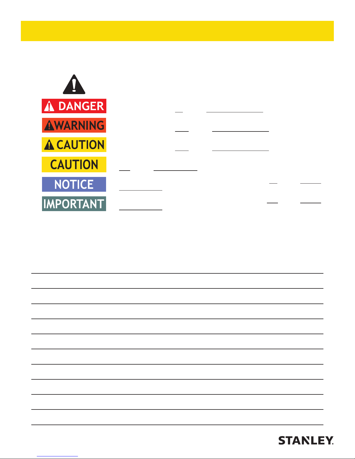
SAFETY SYMBOLS
Safety symbols and signal words, as shown below, are used to emphasize all operator, maintenance and repair
actions which, if not strictly followed, could result in a life-threatening situation, bodily injury or damage to equipment.
This is the safety alert symbol. It is used to alert you to potential personal injury
hazards. Obey all safety messages that follow this symbol to avoid possible
injury or death.
This safety alert and signal word indicates an imminently hazardous situation
which, if not avoided, will result in death or serious injury.
This safety alert and signal word indicates a potentially hazardous situation
which, if not avoided, could result in death or serious injury.
This safety alert and signal word indicates a potentially hazardous situation
which, if not avoided, could result in death or serious injury.
This signal word indicates a potentially hazardous situation which, if not avoided,
may result in property damage.
This signal word indicates a situation which, if not avoided, will result in damage
to the equipment.
This signal word indicates a situation which, if not avoided, may result in damage
to the equipment.
Always observe safety symbols. They are included for your safety and for the protection of the tool.
LOCAL SAFETY REGULATIONS
Enter any local safety regulations here. Keep these instructions in an area accessible to the operator and
maintenance personnel.
4 ► BR87 User Manual

SAFETY PRECAUTIONS
Tool operators and maintenance personnel must always
comply with the safety precautions given in this manual
and on the stickers and tags attached to the tool and
hose.
These safety precautions are given for your safety.
Review them carefully before operating the tool and
before performing general maintenance or repairs.
Supervising personnel should develop additional
precautions relating to the specic work area and local
safety regulations. If so, place the added precautions in
the space provided in this manual.
The BR87 Hydraulic Breaker will provide safe and
dependable service if operated in accordance with the
instructions given in this manual. Read and understand
this manual and any stickers and tags attached to the
tool and hoses before operation. Failure to do so could
result in personal injury or equipment damage.
• Operator must start in a work area without bystanders
and must assess the risk to bystanders.
• Operators and maintenance personnel shall be able
to physically handle the bulk, weight and power of
the tool.
• The operator must be familiar with all prohibited work
areas such as excessive slopes and dangerous
terrain conditions.
• Establish a training program for all operators to
ensure safe operation.
• Do not operate the tool unless thoroughly trained or
under the supervision of an instructor.
• Always wear safety equipment such as goggles,
gloves, ear, head and breathing protection, and
safety shoes at all times when operating the tool.
• Do not inspect, carry or clean the tool while the
hydraulic power source is connected. Accidental
engagement of the tool can cause serious injury.
• Supply hoses must have a minimum working
pressure rating of 2500 psi/175 bar.
• Be sure all hose connections are tight.
• The hydraulic circuit control valve must be in the
“OFF” position when coupling or uncoupling the tool.
Wipe all couplers clean before connecting. Use only
lint-free cloths. Failure to do so may result in damage
to the quick couplers and cause overheating of the
hydraulic system.
• Do not operate the tool at oil temperatures above
140 °F/60 °C. Operation at higher oil temperatures
can cause operator discomfort and may damage the
tool. Never come in contact with the tool bit as the
bit can get hot.
• When using a non-rotary percussive tool to perform
work related activities, the operator can experience
discomfort in the hands, arms, shoulders, neck or
other parts of the body.
• If you experience numbness, tingling, pain or whit-
ening of the skin in your ngers or hands, stop using
the tool. Tell your employer and consult a physician.
• Do not operate a damaged, improperly adjusted or
incompletely assembled tool.
• Inspect the tool before each use and ensure all decals are legible. Contact STANLEY if replacements
are needed.
• Do not weld, cut with an acetylene torch or hard-
face the tool bit.
• To avoid personal injury or equipment damage,
all tool repair, maintenance and service must only
be performed by authorized and properly trained
personnel.
• Do not exceed the rated limits of the tool or use the
tool for applications beyond it’s design capacity.
• Always replace parts with replacement parts
recommended by STANLEY.
• Ensure work piece is securely xed. Be aware that
failure of the work piece or accessories may generate high velocity projectiles.
• WARNING: Some dust created by power sanding,
sawing, grinding, drilling, and other construction
activities contains chemicals known to the State
of California to cause cancer, birth defects or
other reproductive harm. Some examples of these
chemicals are:
• Lead from lead-based paints,
• crystalline silica from bricks and cement
and other masonry products, and
• arsenic and chromium from chemicallytreated lumber.
Your risk from these exposures varies, depending
on how often you do this type of work. To reduce
your exposure to these chemicals: work in a well
ventilated area, and work with approved safety
equipment, such as those dust masks that are
specially designed to lter out microscopic particles.
Protect yourself and those around you. Research
BR87 User Manual ◄ 5

SAFETY PRECAUTIONS
and understand the materials you are cutting.
Follow correct safety procedures and comply with
all applicable national, state or provisional health
and safety regulations relating to them, including,
if appropriate arranging for the safe disposal of the
materials by a qualied person.
• Check fastener tightness often and before each use
daily.
• Never operate the tool if you cannot be sure that
underground utilities are not present, such as
electrical cables, gas pipes, etc. These can cause a
hazard if damaged with the tool.
• The tool is not insulated against coming into contact
with electric power.
• Do not wear loose tting clothing when operating the
tool.
• Warning: Hydraulic uid under pressure could cause
skin injection injury. If you are injured by hydraulic
uid, get medical attention immediately.
• Keep all body parts away from the working tool.
• When handling material or the tool bit, wear your
Personal Protection Equipment (PPE).
• Be observant of the hydraulic hoses lying about the
work area as they can be a tripping hazard.
• Always de-energize the hydraulic system when
changing a tool bit.
• Take caution when changing a tool bit. Tool bits can
get very hot.
• Never use the tool in an explosive atmosphere.
Sparks from the breaking process could ignite
explosive gas.
• Use proper lifting techniques when handling the tool.
Get help from a co-worker and do not over-reach.
• Use proper protection from falling or ying debris.
Keep bystanders at a safe distance.
• Do not exceed the rated ow and pressure. See
“SPECIFICATIONS” on page 17 for correct ow
rate and pressure rating. Rapid failure of the internal
seals may result.
• Do not exceed the maximum relief valve setting
stated on the tool.
6 ► BR87 User Manual
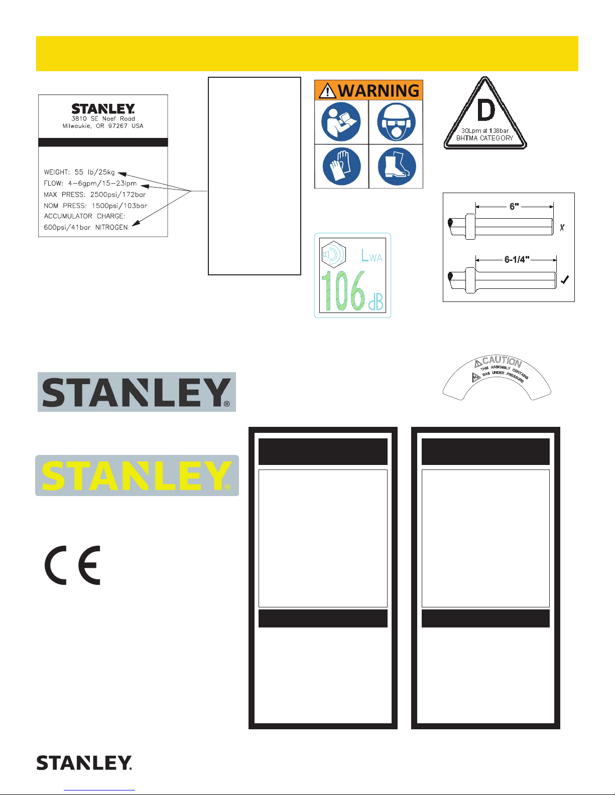
BR87
B
R
AKE
E
74673
BR87 Name Tag Decal
Used on Models:
BR87120
BR87120E
BR87120J
BR87130
BR87130E
BR8713201FS
BR8717201
BR87320
R
74666
BR87 Name Tag
Decal
Used on Models:
BR87120D
TOOL STICKERS & TAGS
These numbers
are for example
only and may
not relate to your
model of breaker,
see part number
below for name
tag sticker that
ts your model
breaker.
Note: The serial
number and year
of manufacture
are stamped on
the tool, near the
trigger.
28409
Composite Decal
72786
Guaranteed Sound Power
Level Decal
11207
Circuit Type C Decal
11208
Hex Shank Decal (CE Model ONLY)
Used on Models:
BR8717201
74832
STANLEY Logo (Used on Models: BR87120,
BR87120E, BR87130, BR87130E, BR8713201FS &
BR8717201).
74832
STANLEY Logo Used on Models: BR87120D,
BR87120J & BR87320).
28322
CE Decal
The safety tag (P/N 15875) at right is attached to
the tool when shipped from the factory. Read and
understand the safety instructions listed on this
tag before removal. We suggest you retain this
tag and attach it to the tool when not in use.
1. FAILURE TO USE HYDRAULIC HOSE LABELED AND CERTIFIED AS NON-CONDUCTIVE WHEN USING HYDRAULIC
TOOLS ON OR NEAR ELECTRICAL LINES MAY RESULT IN
DEATH OR SERIOUS INJURY.
BEFORE USING HOSE LABELED AND CERTIFIED AS NON-
CONDUCTIVE ON OR NEAR ELECTRIC LINES BE SURE THE
HOSE IS MAINTAINED AS NON-CONDUCTIVE. THE HOSE
SHOULD BE REGULARLY TESTED FOR ELECTRIC CURRENT LEAKAGE IN ACCORDANCE WITH YOUR SAFETY
DEPARTMENT INSTRUCTIONS.
2. A HYDRAULIC LEAK OR BURST MAY CAUSE OIL INJECTION INTO THE BODY OR CAUSE OTHER SEVERE
PERSONAL INJURY.
A. DO NOT EXCEED SPECIFIED FLOW AND PRESSURE
FOR THIS TOOL. EXCESS FLOW OR PRESSURE MAY
CAUSE A LEAK OR BURST.
B. DO NOT EXCEED RATED WORKING PRESSURE OF
HYDRAULIC HOSE USED WITH THIS TOOL. EXCESS
PRESSURE MAY CAUSE A LEAK OR BURST.
C. CHECK TOOL HOSE COUPLERS AND CONNECTORS
DAILY FOR LEAKS. DO NOT FEEL FOR LEAKS WITH
YOUR HANDS. CONTACT WITH A LEAK MAY RESULT
IN SEVERE PERSONAL INJURY.
IMPORTANT
READ OPERATION MANUAL AND
SAFETY INSTRUCTIONS FOR THIS
TOOL BEFORE USING IT.
USE ONLY PARTS AND REPAIR
PROCEDURES APPROVED BY
STANLEY AND DESCRIBED IN THE
OPERATION MANUAL.
TAG TO BE REMOVED ONLY BY
TOOL OPERATOR.
SEE OTHER SIDE
10180
Caution Decal
DANGERDANGER
D. DO NOT LIFT OR CARRY TOOL BY THE HOSES. DO
NOT ABUSE HOSE. DO NOT USE KINKED, TORN OR
DAMAGED HOSE.
3. MAKE SURE HYDRAULIC HOSES ARE PROPERLY CONNECTED TO THE TOOL BEFORE PRESSURING SYSTEM.
SYSTEM PRESSURE HOSE MUST ALWAYS BE CONNECTED TO TOOL “IN” PORT. SYSTEM RETURN HOSE
MUST ALWAYS BE CONNECTED TO TOOL “OUT” PORT.
REVERSING CONNECTIONS MAY CAUSE REVERSE
TOOL OPERATION WHICH CAN RESULT IN SEVERE
PERSONAL INJURY.
4. DO NOT CONNECT OPEN-CENTER TOOLS TO CLOSEDCENTER HYDRAULIC SYSTEMS. THIS MAY RESULT IN
LOSS OF OTHER HYDRAULIC FUNCTIONS POWERED BY
THE SAME SYSTEM AND/OR SEVERE PERSONAL INJURY.
5. BYSTANDERS MAY BE INJURED IN YOUR WORK AREA.
KEEP BYSTANDERS CLEAR OF YOUR WORK AREA.
6. WEAR HEARING, EYE, FOOT, HAND AND HEAD PROTECTION.
7. TO AVOID PERSONAL INJURY OR EQUIPMENT DAMAGE,
ALL TOOL REPAIR MAINTENANCE AND SERVICE MUST
ONLY BE PERFORMED BY AUTHORIZED AND PROPERLY
TRAINED PERSONNEL.
IMPORTANT
READ OPERATION MANUAL AND
SAFETY INSTRUCTIONS FOR THIS
TOOL BEFORE USING IT.
USE ONLY PARTS AND REPAIR
PROCEDURES APPROVED BY
STANLEY AND DESCRIBED IN THE
OPERATION MANUAL.
TAG TO BE REMOVED ONLY BY
TOOL OPERATOR.
SEE OTHER SIDE
SAFETY TAG P/N 15875 (Shown smaller then actual size)
BR87 User Manual ◄ 7
HOSE TYPES
The rated working pressure of the hydraulic hose must be equal to or higher than the relief valve setting on the
hydraulic system. There are three types of hydraulic hose that meet this requirement and are authorized for use with
STANLEY hydraulic tools. They are:
Certi ed non-conductive — constructed of thermoplastic or synthetic rubber inner tube, synthetic ber braid
reinforcement, and weather resistant thermoplastic or synthetic rubber cover. Hose labeled certifi ed non-
conductive is the only hose authorized for use near electrical conductors.
Wire-braided (conductive) — constructed of synthetic rubber inner tube, single or double wire braid
reinforcement, and weather resistant synthetic rubber cover. This hose is conductive and must never be used
near electrical conductors.
Fabric-braided (not certi ed or labeled non-conductive) — constructed of thermoplastic or synthetic rubber
inner tube, synthetic ber braid reinforcement, and weather resistant thermoplastic or synthetic rubber cover.
This hose is not certifi ed non-conductive and must never be used near electrical conductors.
HOSE SAFETY TAGS
To help ensure your safety, the following DANGER tags are attached to all hose purchased from STANLEY. DO
NOT REMOVE THESE TAGS.
If the information on a tag is illegible because of wear or damage, replace the tag immediately. A new tag may be
obtained from your STANLEY Distributor.
THE TAG SHOWN BELOW IS ATTACHED TO “CERTIFIED NON-CONDUCTIVE” HOSE
DANGER
1. FAILURE TO USE HYDRAULIC HOSE LABELED AND CERTIFIED AS NON-CONDUCTIVE
WHEN USING HYDRAULIC TOOLS ON OR NEAR ELECTRIC LINES MAY RESULT IN
DEATH OR SERIOUS INJURY.
FOR PROPER AND SAFE OPERATION MAKE SURE THAT YOU HAVE BEEN PROPERLY
TRAINED IN CORRECT PROCEDURES REQUIRED FOR WORK ON OR AROUND
ELECTRIC LINES.
2. BEFORE USING HYDRAULIC HOSE LABELED AND CERTIFIED AS NON-CONDUCTIVE
ON OR NEAR ELECTRIC LINES. WIPE THE ENTIRE LENGTH OF THE HOSE AND FITTING
WITH A CLEAN DRY ABSORBENT CLOTH TO REMOVE DIRT AND MOISTURE AND TEST
HOSE FOR MAXIMUM ALLOWABLE CURRENT LEAKAGE IN ACCORDANCE WITH SAFETY
DEPARTMENT INSTRUCTIONS.
DO NOT REMOVE THIS TAG
SEE OTHER SIDE
SIDE 1
3. DO NOT EXCEED HOSE WORKING PRESSURE OR ABUSE HOSE. IMPROPER USE
OR HANDLING OF HOSE COULD RESULT IN BURST OR OTHER HOSE FAILURE.
KEEP HOSE AS FAR AWAY AS POSSIBLE FROM BODY AND DO NOT PERMIT DIRECT
CONTACT DURING USE. CONTACT AT THE BURST CAN CAUSE BODILY INJECTION
AND SEVERE PERSONAL INJURY.
4. HANDLE AND ROUTE HOSE CAREFULLY TO AVOID KINKING, ABRASION, CUTTING, OR
CONTACT WITH HIGH TEMPERATURE SURFACES. DO NOT USE IF KINKED. DO NOT
USE HOSE TO PULL OR LIFT TOOLS, POWER UNITS, ETC.
5. CHECK ENTIRE HOSE FOR CUTS CRACKS LEAKS ABRASIONS, BULGES, OR DAMAGE TO COUPLINGS IF ANY OF THESE CONDITIONS EXIST, REPLACE THE HOSE
IMMEDIATELY. NEVER USE TAPE OR ANY DEVICE TO ATTEMPT TO MEND THE HOSE.
6. AFTER EACH USE STORE IN A CLEAN DRY AREA.
(Shown smaller than actual size)
DANGER
DANGER
SEE OTHER SIDE
SIDE 2
THE TAG SHOWN BELOW IS ATTACHED TO “CONDUCTIVE” HOSE.
DANGER
DANGER
1. DO NOT USE THIS HYDRAULIC HOSE ON OR NEAR ELECTRIC LINES. THIS HOSE IS
NOT LABELED OR CERTIFIED AS NON-CONDUCTIVE. USING THIS HOSE ON OR NEAR
ELECTRICAL LINES MAY RESULT IN DEATH OR SERIOUS INJURY.
2. FOR PROPER AND SAFE OPERATION MAKE SURE THAT YOU HAVE BEEN PROPERLY
TRAINED IN CORRECT PROCEDURES REQUIRED FOR WORK ON OR AROUND ELECTRIC LINES.
3. DO NOT EXCEED HOSE WORKING PRESSURE OR ABUSE HOSE. IMPROPER USE OR
HANDLING OF HOSE COULD RESULT IN BURST OR OTHER HOSE FAILURE. KEEP HOSE
AS FAR AWAY AS POSSIBLE FROM BODY AND DO NOT PERMIT DIRECT CONTACT
DURING USE. CONTACT AT THE BURST CAN CAUSE BODILY INJECTION AND SEVERE
PERSONAL INJURY.
4. HANDLE AND ROUTE HOSE CAREFULLY TO AVOID KINKING, CUTTING, OR CONTACT
WITH HIGH TEMPERATURE SURFACES. DO NOT USE IF KINKED. DO NOT USE HOSE TO
PULL OR LIFT TOOLS, POWER UNITS, ETC.
DO NOT REMOVE THIS TAG
SEE OTHER SIDE
SIDE 1
5. CHECK ENTIRE HOSE FOR CUTS CRACKS LEAKS ABRASIONS, BULGES, OR DAMAGE TO
COUPLINGS IF ANY OF THESE CONDITIONS EXIST, REPLACE THE HOSE IMMEDIATELY.
NEVER USE TAPE OR ANY DEVICE TO ATTEMPT TO MEND THE HOSE.
6. AFTER EACH USE STORE IN A CLEAN DRY AREA.
(Shown smaller than actual size)
DANGER
SEE OTHER SIDE
SIDE 2
DO NOT REMOVE THIS TAG
DO NOT REMOVE THIS TAG
8 ► BR87 User Manual
Min. Working Pressure
USE
Press/Return)
(
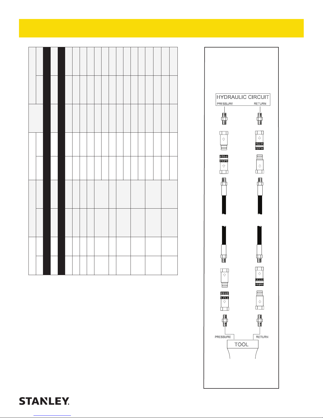
HOSE RECOMMENDATIONS
Certi ed Non-Conductive Hose - Fiber Braid - for Utility Bucket Trucks
Oil Flow Hose Lengths Inside Diameter
GPM LPM FEET METERS INCH MM PSI BAR
4-9 15-34 up to 10 up to 3 3/8 10 Both 2250 155
Conductive Hose - Wire Braid or Fiber Braid -DO NOT USE NEAR ELECTRICAL CONDUCTORS
4-6 15-23 up to 25 up to 7.5 3/8 10 Both 2500 175
4-6 15-23 26-100 7.5-30 1/2 13 Both 2500 175
5-10.5 19-40 up to 50 up to 15 1/2 13 Both 2500 175
5-10.5 19-40 51-100 15-30 5/8 16 Both 2500 175
5/8 16 Pressure 2500 175
3/4 19 Return 2500 175
5-10.5 19-40 100-300 30-90
10-13 38-49 up to 50 up to 15 5/8 16 Both 2500 175
5/8 16 Pressure 2500 175
3/4 19 Return 2500 175
10-13 38-49 51-100 15-30
3/4 19 Pressure 2500 175
1 25.4 Return 2500 175
10-13 38-49 100-200 30-60
5/8 16 Pressure 2500 175
13-16 49-60 up to 25 up to 8
3/4 19 Return 2500 175
3/4 19 Pressure 2500 175
1 25.4 Return 2500 175
13-16 49-60 26-100 8-30
PRESSURE
<<< FLOW
RETURN
FLOW >>>
Figure 1. Typical Hose Connections
Tool to Hydraulic Circuit Hose
Recommendations
The chart to the right shows recommended
minimum hose diameters for various
hose lengths based on gallons per minute
(GPM)/liters per minute (LPM). These
recommendations are intended to keep return
line pressure (back pressure) to a minimum
acceptable level to ensure maximum tool
performance.
This chart is intended to be used for hydraulic
tool applications only based on STANLEY tool
operating requirements and should not be
used for any other applications.
All hydraulic hose must have at least a
rated minimum working pressure equal to
the maximum hydraulic system relief valve
setting.
All hydraulic hose must meet or exceed
speci cations as set forth by SAE J517.
BR87 User Manual ◄ 9
 Loading...