

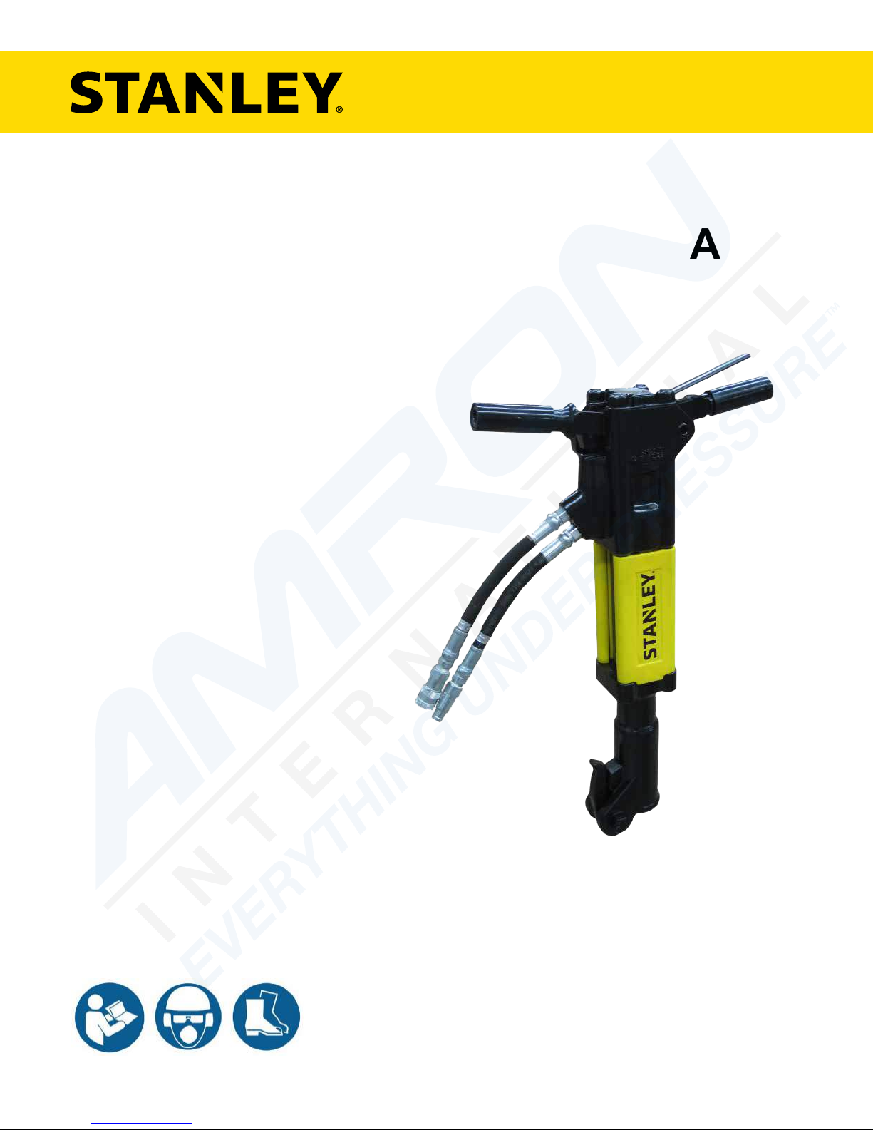
BR45
HYDRAULIC
BREAKER
USER MANUAL
Safety, Operation and Maintenance
© 2014 STANLEY Black & Decker, Inc.
New Britain, CT 06053
U.S.A.
62388 11/2017 Ver. 14
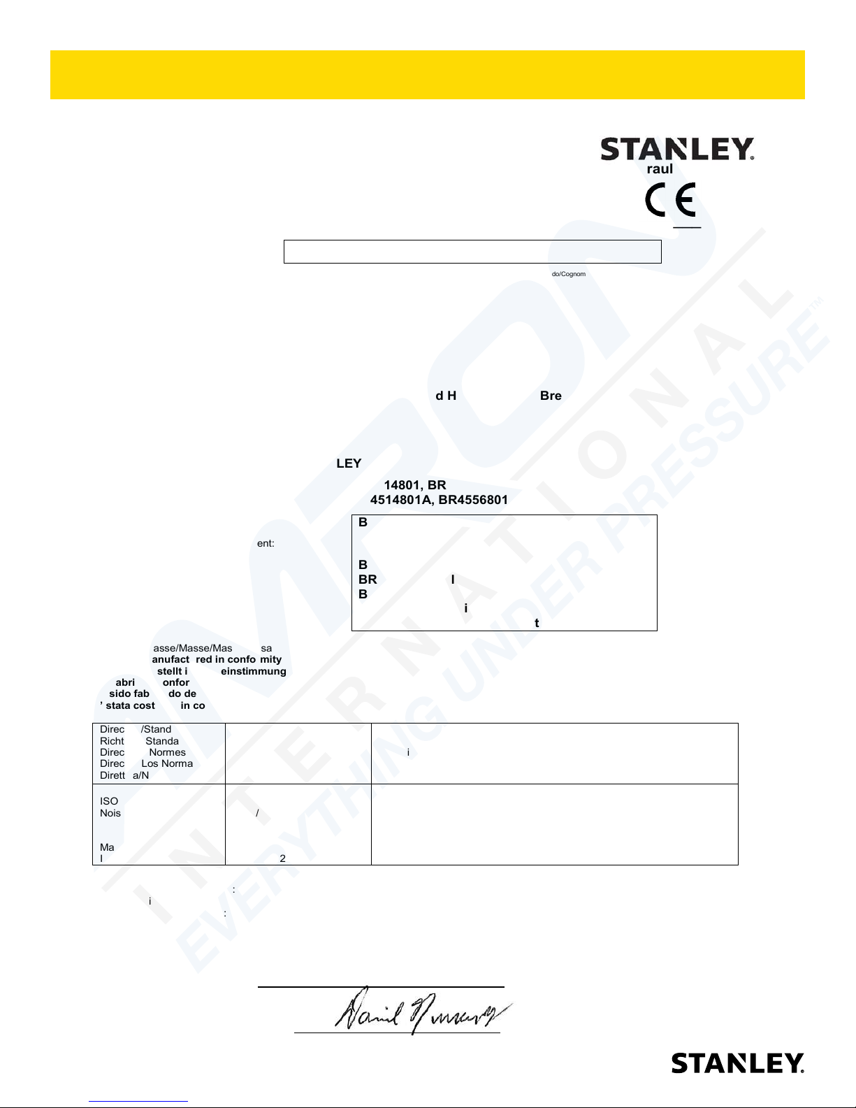
DECLARATION OF CONFORMITY
ÜBEREINSTIMMUNGS-ERKLARUNG
DECLARATION DE CONFORMITE CEE
DECLARACION DE CONFORMIDAD
DICHIARAZIONE DI CONFORMITA
Hydraulic Tools
______________________________________________________________________
I, the undersigned:
Ich, der Unterzeichnende:
Je soussigné:
El abajo firmante:
lo sottoscritto:
Nuerenberg, David
Surname and First names/Familiennname und Vornamen/Nom et prénom/ Nombre y apellido/Cognome e nome
hereby declare that the equipment specified hereunder:
bestätige hiermit, daß erklaren Produkt genannten Werk oder Gerät:
déclare que l’équipement visé ci-dessous:
Por la presente declaro que el equipo se especifica a continuación:
Dichiaro che le apparecchiature specificate di seguito:
1. Category:
Hydraulic Hand Held Concrete Breaker
Kategorie:
Catégorie:
Categoria:
Categoria:
2. Make/Marke/Marque/Marca/Marca
STANLEY
3. Type/Typ/Type/Tipo/Tipo:
BR4514801, BR4516801, BR4516807, BR4516807A
BR4514801A, BR4556801, (BR45350 – For Underwater Use Only)
4. Serial number of equipment:
Seriennummer des Geräts:
Numéro de série de l’équipement:
Numero de serie del equipo:
Matricola dell´attrezzatura:
BR4514801 All
BR4514801A All
BR4516801 All
BR4516807 All
BR4516807A All
BR4556801 All
BR45350 Serial # 030612029 and above
(For Underwater Use Only)
5. Mass/Masse/Masse/Masa/Massa 23 kg
Has been manufactured in conformity with
Wurde hergestellt in Übereinstimmung mit
Est fabriqué conformément
Ha sido fabricado de acuerdo con
E’ stata costruita in conformitá con
Directive/Standards
Richtlinie/Standards
Directives/Normes
Directriz/Los Normas
Direttiva/Norme
No.
Nr
Numéro
No
n.
Approved body
Prüfung durch
Organisme agréé
Aprobado
Collaudato
ISO
Noise Directive
Machinery Directive
ISO
11148-4:2012
2000/14/EC:2005
3744:2010
2006/42/EC:2006
28927-10:2011
Self
AkustikNet (Notified body ID 1585)
Bagsvard Hovedgade 141, 2880 Bagsvard, Denmark
Certificate #863/2011/002 (Verification 2015-08-04) Valid: 12/31/2018
Self
Self
6. Special Provisions: None 7. Measurements: Measured Sound Power Level 105 LwA
Spezielle Bestimmungen: Messungen Guaranteed Sound Power Level 107 LwA
Dispositions particulières: Mesures Measured in accordance to Directive 2000/14/EC,
Provisiones especiales: Mediciones Annex III, Part B, No 10, 15 kg<m< 30 kg
Disposizioni speciali: Misurazioni
8. Representative in the Union: Patrick Vervier, Stanley Dubuis 17-19, rue Jules Berthonneau-BP 3406 41034 Blois Cedex, France.
Vertreter in der Union/Représentant dans l’union/Representante en la Union/Rappresentante presso l’Unione
Done at/Ort/Fait à/Dado en/Fatto a Stanley Infrastructure, Milwaukie, Oregon USA Date/Datum/le/Fecha/Data 8-4-2015
Signature/Unterschrift/Signature/Firma/Firma
Position/Position/Fonction/Cargo/Posizione North America Quality Manager
DECLARATION OF CONFORMITY
2 ► BR45 User Manual
TABLE OF CONTENTS
SAFETY SYMBOLS ..................................................................................................................................................4
SAFETY PRECAUTIONS .......................................................................................................................................... 5
TOOL STICKERS & TAGS ........................................................................................................................................ 6
HOSE TYPES ............................................................................................................................................................7
HOSE RECOMMENDATIONS ..................................................................................................................................8
HTMA / EHTMA REQUIREMENTS ...........................................................................................................................9
OPERATION ............................................................................................................................................................ 10
TOOL PROTECTION & CARE ................................................................................................................................ 11
TROUBLESHOOTING ............................................................................................................................................12
CHARGING THE ACCUMULATOR .........................................................................................................................13
SPECIFICATIONS ................................................................................................................................................... 15
ACCESSORIES.......................................................................................................................................................16
PARTS ILLUSTRATION ..........................................................................................................................................18
PARTS LIST ............................................................................................................................................................19
BR45 ANTI-VIBRATION HANDLE PARTS ILLUSTRATION ...................................................................................20
BR45 ANTI-VIBRATION HANDLE PARTS LIST .....................................................................................................21
BREAKER FOOT ASSEMBLY 07489......................................................................................................................22
BREAKER FOOT ASSEMBLY 07510......................................................................................................................23
BREAKER FOOT ASSEMBLY 07694......................................................................................................................24
BREAKER FOOT ASSEMBLY 07899......................................................................................................................25
BREAKER FOOT ASSEMBLY 08081......................................................................................................................26
BREAKER FOOT ASSEMBLY 08154......................................................................................................................27
BREAKER FOOT ASSEMBLY 08856......................................................................................................................28
BREAKER FOOT ASSEMBLY 62334......................................................................................................................29
BREAKER FOOT ASSEMBLY 72931......................................................................................................................30
UNDERWATER TOOLS DEPTH GUIDELINE .........................................................................................................31
To ll out a product warranty validation form, and for information on your warranty,
visit www.stanleyinfrastructure.com and select the Company tab > Warranty.
Note: The warranty validation record must be submitted to validate the warranty.
SERVICING: This manual contains safety, operation and routine maintenance instructions. STANLEY Infrastructure
recommends that servicing of hydraulic tools, other than routine maintenance, must be performed by an authorized
and certied dealer. Please read the following warning.
SERIOUS INJURY OR DEATH COULD RESULT FROM THE IMPROPER REPAIR OR
SERVICE OF THIS TOOL.
REPAIRS AND / OR SERVICE TO THIS TOOL MUST ONLY BE DONE BY AN
AUTHORIZED AND CERTIFIED DEALER.
For the nearest certied dealer, call STANLEY Infrastructure at (503) 659-5660 and ask for a Customer Service Representative.
BR45 User Manual ◄ 3
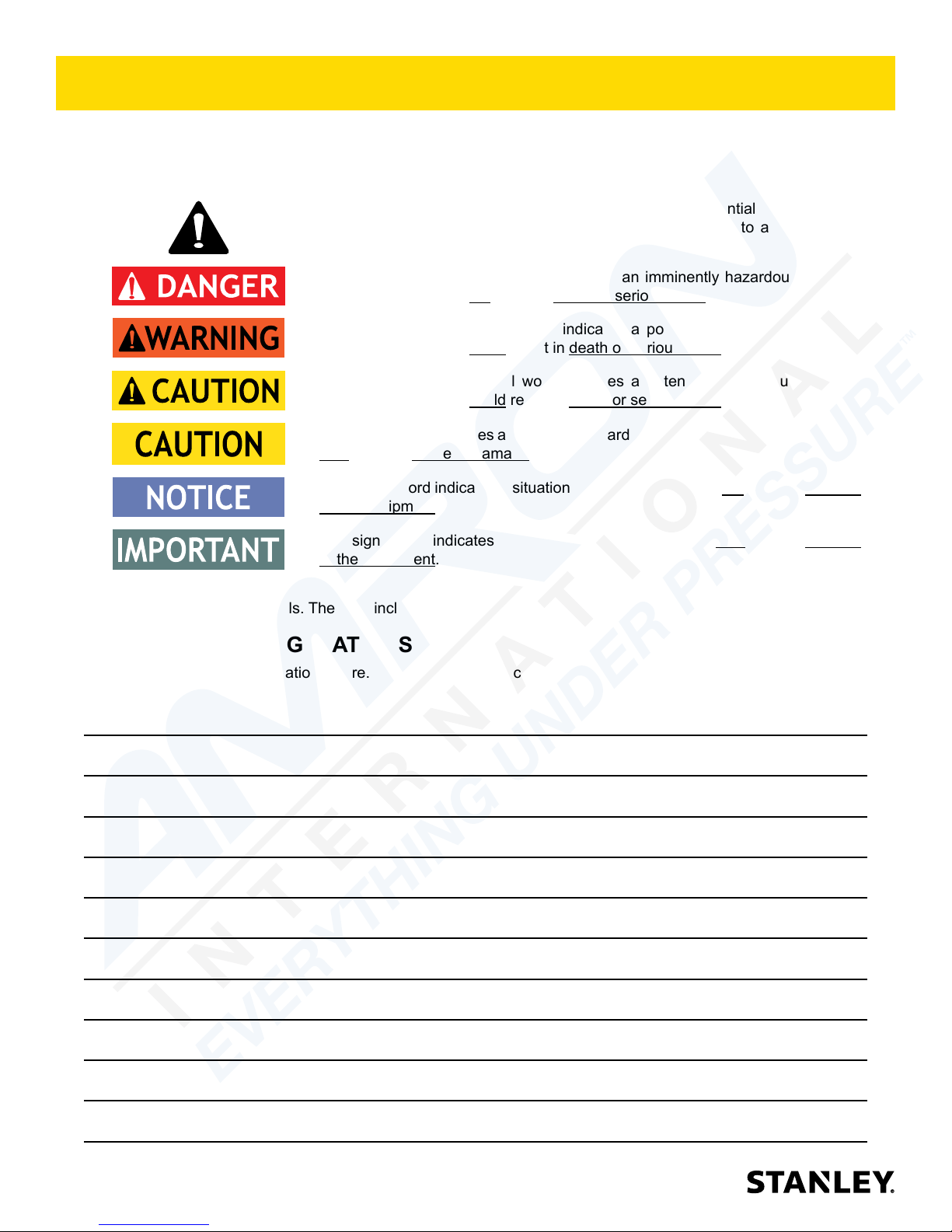
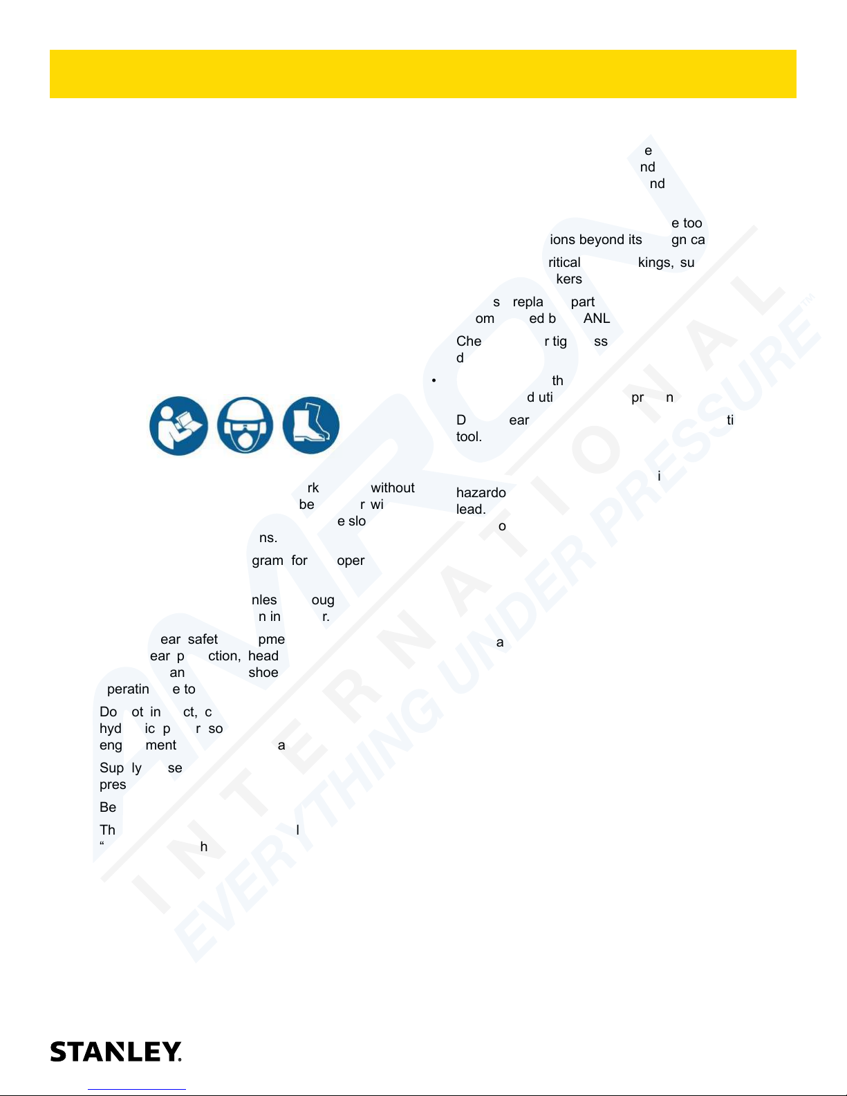
SAFETY SYMBOLS
Safety symbols and signal words, as shown below, are used to emphasize all operator, maintenance and repair
actions which, if not strictly followed, could result in a life-threatening situation, bodily injury or damage to equipment.
This is the safety alert symbol. It is used to alert you to potential personal injury
hazards. Obey all safety messages that follow this symbol to avoid possible
injury or death.
This safety alert and signal word indicates an imminently hazardous situation
which, if not avoided, will result in death or serious injury.
This safety alert and signal word indicates a potentially hazardous situation
which, if not avoided, could result in death or serious injury.
This safety alert and signal word indicates a potentially hazardous situation
which, if not avoided, could result in death or serious injury.
This signal word indicates a potentially hazardous situation which, if not avoided,
may result in property damage.
This signal word indicates a situation which, if not avoided, will result in damage
to the equipment.
This signal word indicates a situation which, if not avoided, may result in damage
to the equipment.
Always observe safety symbols. They are included for your safety and for the protection of the tool.
LOCAL SAFETY REGULATIONS
Enter any local safety regulations here. Keep these instructions in an area accessible to the operator and
maintenance personnel.
4 ► BR45 User Manual
SAFETY PRECAUTIONS
Tool operators and maintenance personnel must always
comply with the precautions given in this manual and on
the stickers and tags attached to the tool and hose.
These precautions are given for your safety. Review
them carefully before operating the tool and before
performing general maintenance or repairs.
Supervising personnel should develop additional
precautions relating to the specic work area and local
safety regulations. Place the added precautions in the
space provided in this manual.
The BR45 Hydraulic Breaker will provide safe and
dependable service if operated in accordance with the
instructions given in this manual. Read and understand
this manual and any stickers and tags attached to the
tool and hoses before operation. Failure to do so could
result in personal injury or equipment damage.
• Operator must start in a work area without
bystanders. The operator must be familiar with all
prohibited work areas such as excessive slopes and
dangerous terrain conditions.
• Establish a training program for all operators to
ensure safe operation.
• Do not operate the tool unless thoroughly trained or
under the supervision of an instructor.
• Always wear safety equipment such as goggles,
gloves, ear protection, head protection, breathing
protection and safety shoes at all times when
operating the tool.
• Do not inspect, carry or clean the tool while the
hydraulic power source is connected. Accidental
engagement of the tool can cause serious injury.
• Supply hoses must have a minimum working
pressure rating of 2500 psi/175 bar.
• Be sure all hose connections are tight.
• The hydraulic circuit control valve must be in the
“OFF” position when coupling or uncoupling the tool.
Wipe all couplers clean before connecting. Use only
lint-free cloths. Failure to do so may result in damage
to the quick couplers and cause overheating of the
hydraulic system.
• Do not operate the tool at oil temperatures above
140 °F/60 °C. Operation at higher oil temperatures
can cause operator discomfort and may damage the
tool. Never contact the tool bit, the bit can get hot.
• Do not operate a damaged, improperly adjusted or
incompletely assembled tool.
• Do not weld, cut with an acetylene torch or hardface the tool bit.
• To avoid personal injury or equipment damage,
all tool repair, maintenance and service must only
be performed by authorized and properly trained
personnel.
• Do not exceed the rated limits of the tool or use the
tool for applications beyond its design capacity.
• Always keep critical tool markings, such as labels
and warning stickers, legible.
• Always replace parts with replacement parts
recommended by STANLEY.
• Check fastener tightness often and before each use
daily.
• Never operate the tool if you cannot be sure that
underground utilities are not present.
• Do not wear loose tting clothing when operating the
tool.
• Warning: Use of this tool on certain materials could
generate dust potentially containing a variety of
hazardous substances such as asbestos, silica or
lead. Inhalation of dust containing these or other
hazardous substances could result in serious
injury, cancer or death. Protect yourself and those
around you. Research and understand the materials
you are cutting. Follow correct safety procedures
and comply with all applicable national, state or
provisional health and safety regulations relating to
them, including, if appropriate arranging for the safe
disposal of the materials by a qualied person.
• Warning: Hydraulic uid under pressure could
cause skin injection injury. If you are injured by
hydraulic uid, get medical attention immediately.
• Keep all body parts away from the working tool.
• When handling material or the tool bit, wear your
Personal Protection Equipment (PPE).
• Be observant of the hydraulic hoses lying about the
work area. They can be a tripping hazard.
• Always de-energize the hydraulic system when
changing a tool bit.
• Never use the tool in an explosive atmosphere.
Sparks could ignite explosive gas.
• Use proper lifting techniques when handling the tool.
Get help from a co-worker and do not over-reach.
• Use proper protection from falling or ying debris
and keep bystanders at a safe distance.
• Do not exceed the rated ow and pressure. See
Specications in this manual for correct ow rate
and pressure rating. Rapid failure of the internal
seals may result.
BR45 User Manual ◄ 5
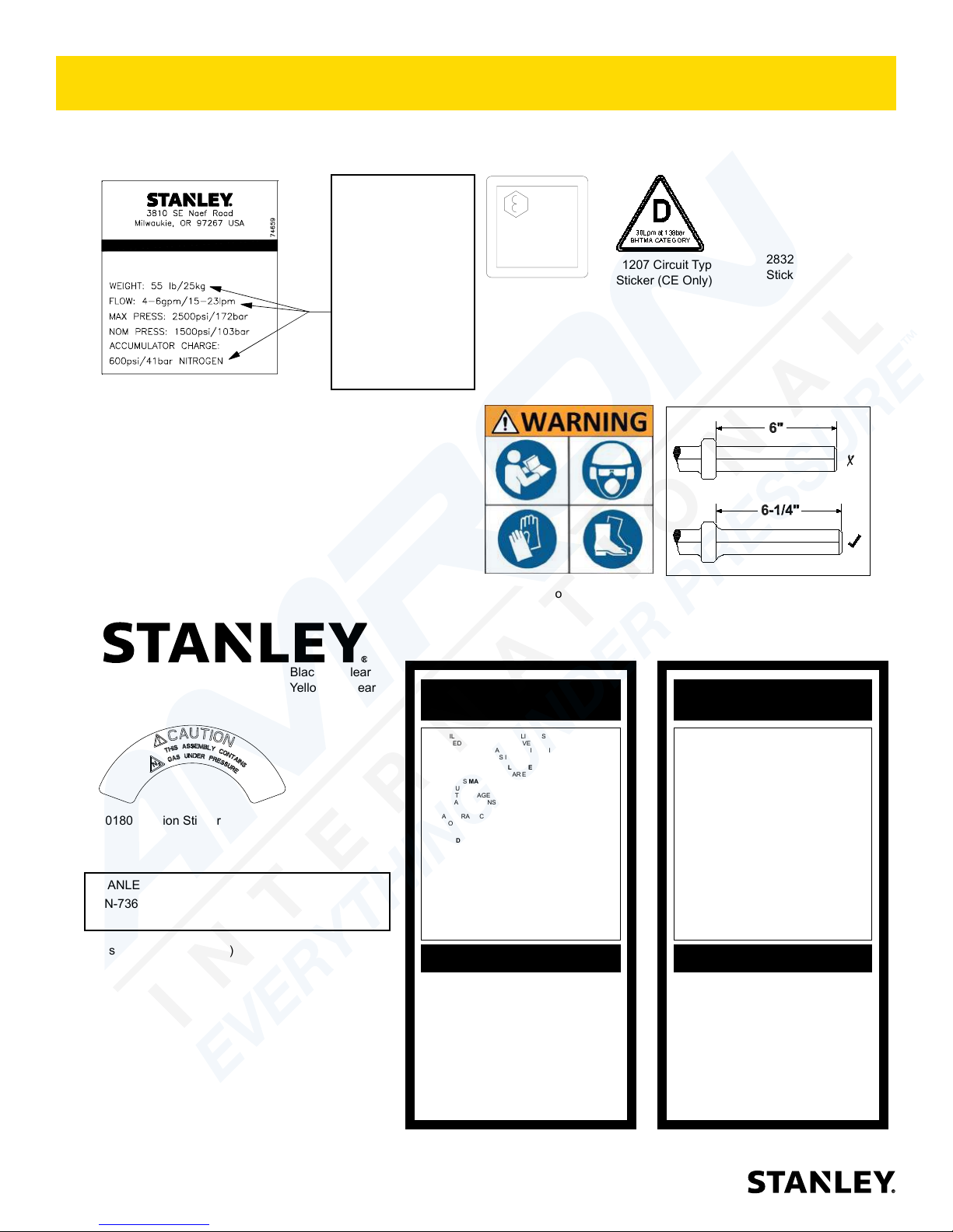
TOOL STICKERS & TAGS
Please refer to the Parts Illustration for location of stickers.
BR45 BREAKER
74659 5-GPM Anti-Vib Name
Tag Sticker
74660 5-GPM T-Handle Name
Tag Sticker
74663 8-GPM Anti-Vib Name
Tag Sticker
74664 8-GPM T-Handle Name
Tag Sticker
74669 8-GPM T-Handle Name
Tag Sticker Under Water
These numbers
are for example
only and may
not relate to your
model of breaker,
see part numbers
below for name
tag stickers that
ts your model
breaker.
Lwa
107
58601 Sound Level
Sticker (CE Only)
28409 Composite
Sticker (CE Only)
11207 Circuit Type C
Sticker (CE Only)
11208 Hex Shank
Length Sticker
28322 CE
Sticker (CE Only)
74832 STANLEY Logo 5.5” x 1.1” Black on Clear
74770 STANLEY Logo 6.5” x 1.3” Yellow on Clear
10180 Caution Sticker
STANLEY Railroad Help Desk Sticker (Not Pictured)
P/N-73680
The safety tag (P/N 15875) at right is attached to
the tool when shipped from the factory. Read and
understand the safety instructions listed on this tag
before removal. We suggest you retain this tag and
attach it to the tool when not in use.
1. FAILURE TO USE HYDRAULIC HOSE LABELED AND CERTIFIED AS NON-CONDUCTIVE WHEN USING HYDRAULIC
TOOLS ON OR NEAR ELECTRICAL LINES MAY RESULT IN
DEATH OR SERIOUS INJURY.
BEFORE USING HOSE LABELED AND CERTIFIED AS NONCONDUCTIVE ON OR NEAR ELECTRIC LINES BE SURE THE
HOSE IS MAINTAINED AS NON-CONDUCTIVE. THE HOSE
SHOULD BE REGULARLY TESTED FOR ELECTRIC CURRENT LEAKAGE IN ACCORDANCE WITH YOUR SAFETY
DEPARTMENT INSTRUCTIONS.
2. A HYDRAULIC LEAK OR BURST MAY CAUSE OIL INJECTION INTO THE BODY OR CAUSE OTHER SEVERE
PERSONAL INJURY.
A. DO NOT EXCEED SPECIFIED FLOW AND PRESSURE
FOR THIS TOOL. EXCESS FLOW OR PRESSURE MAY
CAUSE A LEAK OR BURST.
B. DO NOT EXCEED RATED WORKING PRESSURE OF
HYDRAULIC HOSE USED WITH THIS TOOL. EXCESS
PRESSURE MAY CAUSE A LEAK OR BURST.
C. CHECK TOOL HOSE COUPLERS AND CONNECTORS
DAILY FOR LEAKS. DO NOT FEEL FOR LEAKS WITH
YOUR HANDS. CONTACT WITH A LEAK MAY RESULT
IN SEVERE PERSONAL INJURY.
IMPORTANT
READ OPERATION MANUAL AND
SAFETY INSTRUCTIONS FOR THIS
TOOL BEFORE USING IT.
USE ONLY PARTS AND REPAIR
PROCEDURES APPROVED BY
STANLEY AND DESCRIBED IN THE
OPERATION MANUAL.
TAG TO BE REMOVED ONLY BY
TOOL OPERATOR.
SEE OTHER SIDE
DANGERDANGER
D. DO NOT LIFT OR CARRY TOOL BY THE HOSES. DO
NOT ABUSE HOSE. DO NOT USE KINKED, TORN OR
DAMAGED HOSE.
3. MAKE SURE HYDRAULIC HOSES ARE PROPERLY CONNECTED TO THE TOOL BEFORE PRESSURING SYSTEM.
SYSTEM PRESSURE HOSE MUST ALWAYS BE CONNECTED TO TOOL “IN” PORT. SYSTEM RETURN HOSE
MUST ALWAYS BE CONNECTED TO TOOL “OUT” PORT.
REVERSING CONNECTIONS MAY CAUSE REVERSE
TOOL OPERATION WHICH CAN RESULT IN SEVERE
PERSONAL INJURY.
4. DO NOT CONNECT OPEN-CENTER TOOLS TO CLOSEDCENTER HYDRAULIC SYSTEMS. THIS MAY RESULT IN
LOSS OF OTHER HYDRAULIC FUNCTIONS POWERED BY
THE SAME SYSTEM AND/OR SEVERE PERSONAL INJURY.
5. BYSTANDERS MAY BE INJURED IN YOUR WORK AREA.
KEEP BYSTANDERS CLEAR OF YOUR WORK AREA.
6. WEAR HEARING, EYE, FOOT, HAND AND HEAD PROTECTION.
7. TO AVOID PERSONAL INJURY OR EQUIPMENT DAMAGE,
ALL TOOL REPAIR MAINTENANCE AND SERVICE MUST
ONLY BE PERFORMED BY AUTHORIZED AND PROPERLY
TRAINED PERSONNEL.
IMPORTANT
READ OPERATION MANUAL AND
SAFETY INSTRUCTIONS FOR THIS
TOOL BEFORE USING IT.
USE ONLY PARTS AND REPAIR
PROCEDURES APPROVED BY
STANLEY AND DESCRIBED IN THE
OPERATION MANUAL.
TAG TO BE REMOVED ONLY BY
TOOL OPERATOR.
SEE OTHER SIDE
6 ► BR45 User Manual
SAFETY TAG P/N 15875 (Shown smaller then actual size)
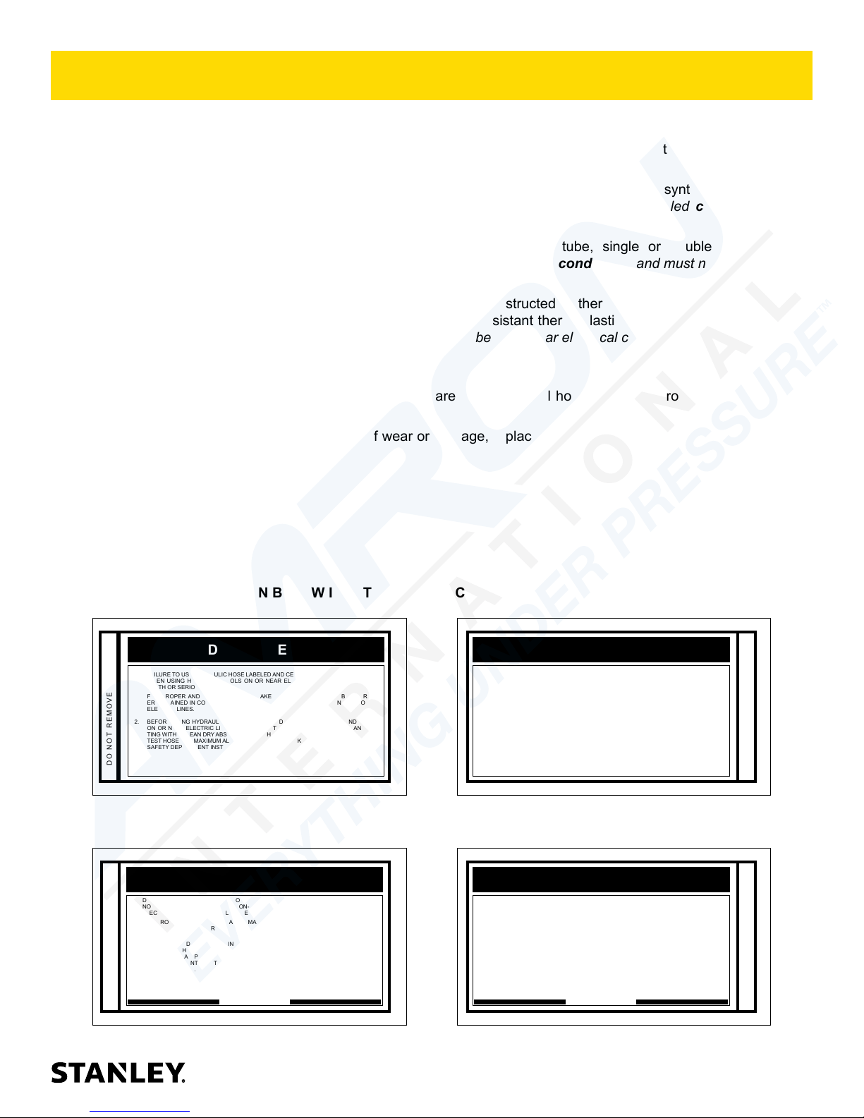
HOSE TYPES
The rated working pressure of the hydraulic hose must be equal to or higher than the relief valve setting on the
hydraulic system. There are three types of hydraulic hose that meet this requirement and are authorized for use with
STANLEY hydraulic tools. They are:
Certied non-conductive — constructed of thermoplastic or synthetic rubber inner tube, synthetic ber braid
reinforcement, and weather resistant thermoplastic or synthetic rubber cover. Hose labeled certied non-
conductive is the only hose authorized for use near electrical conductors.
Wire-braided (conductive) — constructed of synthetic rubber inner tube, single or double wire braid
reinforcement, and weather resistant synthetic rubber cover. This hose is conductive and must never be used
near electrical conductors.
Fabric-braided (not certied or labeled non-conductive) — constructed of thermoplastic or synthetic rubber
inner tube, synthetic ber braid reinforcement, and weather resistant thermoplastic or synthetic rubber cover.
This hose is not certied non-conductive and must never be used near electrical conductors.
HOSE SAFETY TAGS
To help ensure your safety, the following DANGER tags are attached to all hose purchased from STANLEY. DO
NOT REMOVE THESE TAGS.
If the information on a tag is illegible because of wear or damage, replace the tag immediately. A new tag may be
obtained from your STANLEY Distributor.
THE TAG SHOWN BELOW IS ATTACHED TO “CERTIFIED NON-CONDUCTIVE” HOSE
DANGER
1. FAILURE TO USE HYDRAULIC HOSE LABELED AND CERTIFIED AS NON-CONDUCTIVE
WHEN USING HYDRAULIC TOOLS ON OR NEAR ELECTRIC LINES MAY RESULT IN
DEATH OR SERIOUS INJURY.
FOR PROPER AND SAFE OPERATION MAKE SURE THAT YOU HAVE BEEN PROPERLY TRAINED IN CORRECT PROCEDURES REQUIRED FOR WORK ON OR AROUND
ELECTRIC LINES.
2. BEFORE USING HYDRAULIC HOSE LABELED AND CERTIFIED AS NON-CONDUCTIVE
ON OR NEAR ELECTRIC LINES. WIPE THE ENTIRE LENGTH OF THE HOSE AND FITTING WITH A CLEAN DRY ABSORBENT CLOTH TO REMOVE DIRT AND MOISTURE AND
TEST HOSE FOR MAXIMUM ALLOWABLE CURRENT LEAKAGE IN ACCORDANCE WITH
SAFETY DEPARTMENT INSTRUCTIONS.
DO NOT REMOVE THIS TAG
SEE OTHER SIDE
SIDE 1
3. DO NOT EXCEED HOSE WORKING PRESSURE OR ABUSE HOSE. IMPROPER USE
OR HANDLING OF HOSE COULD RESULT IN BURST OR OTHER HOSE FAILURE.
KEEP HOSE AS FAR AWAY AS POSSIBLE FROM BODY AND DO NOT PERMIT DIRECT
CONTACT DURING USE. CONTACT AT THE BURST CAN CAUSE BODILY INJECTION
AND SEVERE PERSONAL INJURY.
4. HANDLE AND ROUTE HOSE CAREFULLY TO AVOID KINKING, ABRASION, CUTTING, OR
CONTACT WITH HIGH TEMPERATURE SURFACES. DO NOT USE IF KINKED. DO NOT
USE HOSE TO PULL OR LIFT TOOLS, POWER UNITS, ETC.
5. CHECK ENTIRE HOSE FOR CUTS CRACKS LEAKS ABRASIONS, BULGES, OR DAMAGE TO COUPLINGS IF ANY OF THESE CONDITIONS EXIST, REPLACE THE HOSE
IMMEDIATELY. NEVER USE TAPE OR ANY DEVICE TO ATTEMPT TO MEND THE HOSE.
6. AFTER EACH USE STORE IN A CLEAN DRY AREA.
(Shown smaller than actual size)
DANGER
DANGER
SEE OTHER SIDE
SIDE 2
THE TAG SHOWN BELOW IS ATTACHED TO “CONDUCTIVE” HOSE.
DANGER
DANGER
1. DO NOT USE THIS HYDRAULIC HOSE ON OR NEAR ELECTRIC LINES. THIS HOSE IS
NOT LABELED OR CERTIFIED AS NON-CONDUCTIVE. USING THIS HOSE ON OR NEAR
ELECTRICAL LINES MAY RESULT IN DEATH OR SERIOUS INJURY.
2. FOR PROPER AND SAFE OPERATION MAKE SURE THAT YOU HAVE BEEN PROPERLY
TRAINED IN CORRECT PROCEDURES REQUIRED FOR WORK ON OR AROUND ELECTRIC LINES.
3. DO NOT EXCEED HOSE WORKING PRESSURE OR ABUSE HOSE. IMPROPER USE OR
HANDLING OF HOSE COULD RESULT IN BURST OR OTHER HOSE FAILURE. KEEP HOSE
AS FAR AWAY AS POSSIBLE FROM BODY AND DO NOT PERMIT DIRECT CONTACT
DURING USE. CONTACT AT THE BURST CAN CAUSE BODILY INJECTION AND SEVERE
PERSONAL INJURY.
4. HANDLE AND ROUTE HOSE CAREFULLY TO AVOID KINKING, CUTTING, OR CONTACT
WITH HIGH TEMPERATURE SURFACES. DO NOT USE IF KINKED. DO NOT USE HOSE TO
PULL OR LIFT TOOLS, POWER UNITS, ETC.
DO NOT REMOVE THIS TAG
SEE OTHER SIDE
SIDE 1
5. CHECK ENTIRE HOSE FOR CUTS CRACKS LEAKS ABRASIONS, BULGES, OR DAMAGE TO
COUPLINGS IF ANY OF THESE CONDITIONS EXIST, REPLACE THE HOSE IMMEDIATELY.
NEVER USE TAPE OR ANY DEVICE TO ATTEMPT TO MEND THE HOSE.
6. AFTER EACH USE STORE IN A CLEAN DRY AREA.
(Shown smaller than actual size)
DANGER
SEE OTHER SIDE
SIDE 2
DO NOT REMOVE THIS TAG
DO NOT REMOVE THIS TAG
BR45 User Manual ◄ 7
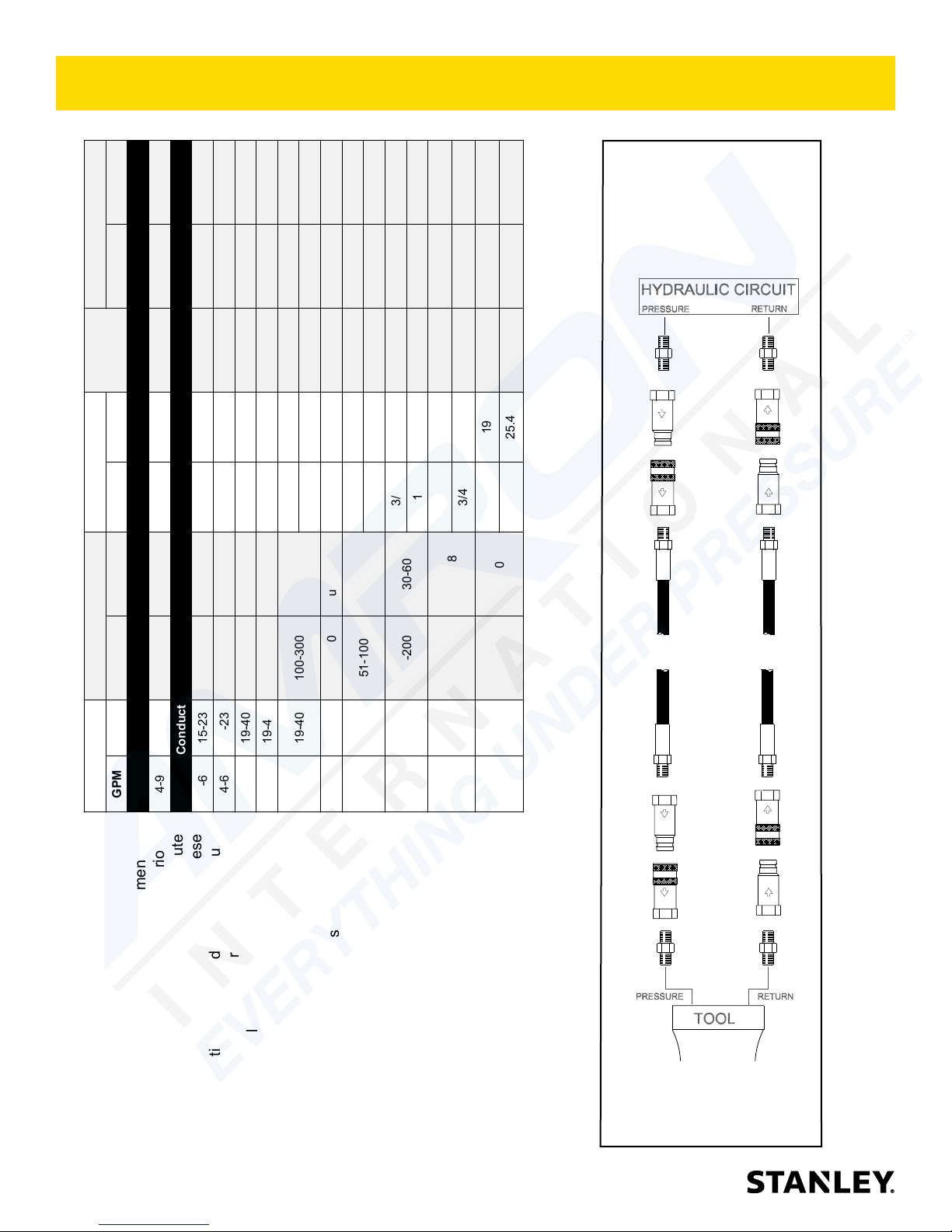
HOSE RECOMMENDATIONS
Min. Working Pressure
USE
Press/Return)
(
Certied Non-Conductive Hose - Fiber Braid - for Utility Bucket Trucks
5/8 16 Pressure 2500 175
3/4 19 Return 2500 175
5/8 16 Pressure 2500 175
3/4 19 Return 2500 175
3/4 19 Pressure 2500 175
1 25.4 Return 2500 175
5/8 16 Pressure 2500 175
3/4 19 Return 2500 175
2500 175
1 25.4 Return 2500 175
3/4 19 Pressure
PRESSURE
<<< FLOW
RETURN
FLOW >>>
Conductive Hose - Wire Braid or Fiber Braid -DO NOT USE NEAR ELECTRICAL CONDUCTORS
Oil Flow Hose Lengths Inside Diameter
Tool to Hydraulic Circuit Hose
4-9 15-34 up to 10 up to 3 3/8 10 Both 2250 155
4-6 15-23 up to 25 up to 7.5 3/8 10 Both 2500 175
GPM LPM FEET METERS INCH MM PSI BAR
Recommendations
The chart to the right shows recommended
minimum hose diameters for various
4-6 15-23 26-100 7.5-30 1/2 13 Both 2500 175
5-10.5 19-40 up to 50 up to 15 1/2 13 Both 2500 175
hose lengths based on gallons per minute
(GPM)/liters per minute (LPM). These
recommendations are intended to keep return
line pressure (back pressure) to a minimum
acceptable level to ensure maximum tool
8 ► BR45 User Manual
5-10.5 19-40 51-100 15-30 5/8 16 Both 2500 175
performance.
10-13 38-49 up to 50 up to 15 5/8 16 Both 2500 175
5-10.5 19-40 100-300 30-90
This chart is intended to be used for hydraulic
tool applications only based on STANLEY tool
operating requirements and should not be
10-13 38-49 51-100 15-30
10-13 38-49 100-200 30-60
13-16 49-60 up to 25 up to 8
used for any other applications.
All hydraulic hose must have at least a
rated minimum working pressure equal to
the maximum hydraulic system relief valve
setting.
13-16 49-60 26-100 8-30
All hydraulic hose must meet or exceed
specications as set forth by SAE J517.
Figure 1. Typical Hose Connections
250 psi 250 psi 250 psi 250 psi
(17 bar) (17 bar) (17 bar) (17 bar)
400 ssu* 400 ssu* 400 ssu* 400 ssu*
(60° C) (60° C) (60° C) (60° C)
(22° C) (22° C) (22° C) (22° C)
30 gpm 30 gpm 30 gpm 30 gpm
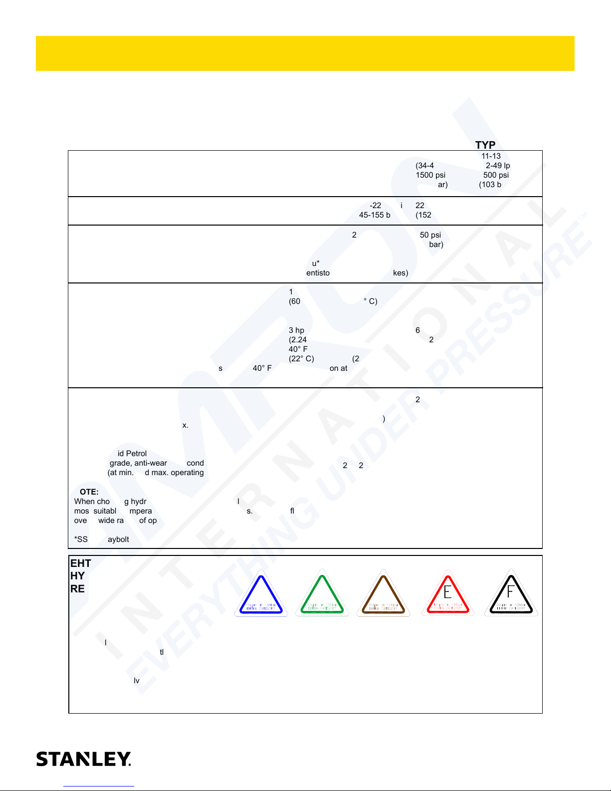
HTMA / EHTMA REQUIREMENTS
HTMA / EHTMA REQUIREMENTS
HTMA
HYDRAULIC SYSTEM REQUIREMENTS
Flow Range
Nominal Operating Pressure
(at the power supply outlet)
System relief valve setting
(at the power supply outlet)
Maximum back pressure
(at tool end of the return hose)
Measured at a max. uid viscosity of:
(at min. operating temperature)
Temperature: Suf cient heat rejection
capacity to limit max. uid temperature to:
(at max. expected ambient temperature)
Min. cooling capacity at a temperature
difference of between ambient and uid
temps
NOTE:
Do not operate the tool at oil temperatures above 140° F (60° C). Operation at higher temperatures can cause operator
discomfort at the tool.
Filter
Min. full- ow ltration
Sized for ow of at least:
(For cold temp. startup and max.
dirt-holding capacity)
4-6 gpm 7-9 gpm 9-10.5 gpm 11-13 gpm
(15-23 lpm) (26-34 lpm) (34-40 lpm) (42-49 lpm)
1500 psi 1500 psi 1500 psi 1500 psi
(103 bar) (103 bar) (103 bar) (103 bar)
2100-2250 psi 2100-2250 psi 2200-2300 psi 2100-2250 psi
(145-155 bar) (145-155 bar) (152-159 bar) (145-155 bar)
(82 centistokes) (82 centistokes) (82 centistokes) (82 centistokes)
140° F 140° F 140° F 140° F
3 hp 5 hp 6 hp 7 hp
(2.24 kW) (3.73 kW) (5.22 kW) (4.47 kW)
40° F 40° F 40° F 40° F
25 microns 25 microns 25 microns 25 microns
(114 lpm) (114 lpm) (114 lpm) (114 lpm)
TYPE I TYPE II
TOOL TYPE
TYPE RR
TYPE III
Hydraulic uid Petroleum based
(premium grade, anti-wear, non-conductive)
Viscosity (at min. and max. operating temps)
NOTE:
When choosing hydraulic uid, the expected oil temperature extremes that will be experienced in service determine the
most suitable temperature viscosity characteristics. Hydraulic uids with a viscosity index over 140 will meet the requirements
over a wide range of operating temperatures.
*SSU = Saybolt Seconds Universal
EHTMA
100-400 ssu* 100-400 ssu* 100-400 ssu* 100-400 ssu*
(20-82 centistokes)
CLASSIFICATION
HYDRAULIC SYSTEM
REQUIREMENTS
Flow Range
Nominal Operating Pressure
(at the power supply outlet)
System relief valve setting
(at the power supply outlet)
NOTE: These are general hydraulic system requirements. See tool speci cation page for tool speci c requirements
B
3.5-4.3 gpm 4.7-5.8 gpm 7.1-8.7 gpm 9.5-11.6 gpm 11.8-14.5 gpm
(13.5-16.5 lpm) (18-22 lpm) (27-33 lpm) (36-44 lpm) (45-55 lpm)
1870 psi 1500 psi 1500 psi 1500 psi 1500 psi
(129 bar) (103 bar) (103 bar) (103 bar) (103 bar)
2495 psi 2000 psi 2000 psi 2000 psi 2000 psi
(172 bar) (138 bar) (138 bar) (138 bar) (138 bar)
C
D
BR45 User Manual ◄ 9
OPERATION
The recommended hose size is .500 inch/12 mm I.D. up
to 50 ft/15 m long and .625 inch/16 mm I.D. minimum up
to 100 ft/30 m.
PRE-OPERATION PROCEDURES
CHECK POWER SOURCE
1. Using a calibrated owmeter and pressure gauge,
check that the hydraulic power source develops a
ow of 7–9 GPM/26–34 LPM at 1500–2000 psi/105–
140 bar or 5–6 GPM /18–22 LPM at 1500–2000 psi
/105–140 bar.
2. Make certain the hydraulic power source is equipped
with a relief valve set to open at 2250 psi/155 bar
maximum.
INSTALL TOOL BIT
1. Rotate the latch on the breaker foot downward
(pointing away from the tool).
2. Insert the tool bit into the foot and pull the latch up to
lock the tool bit in place.
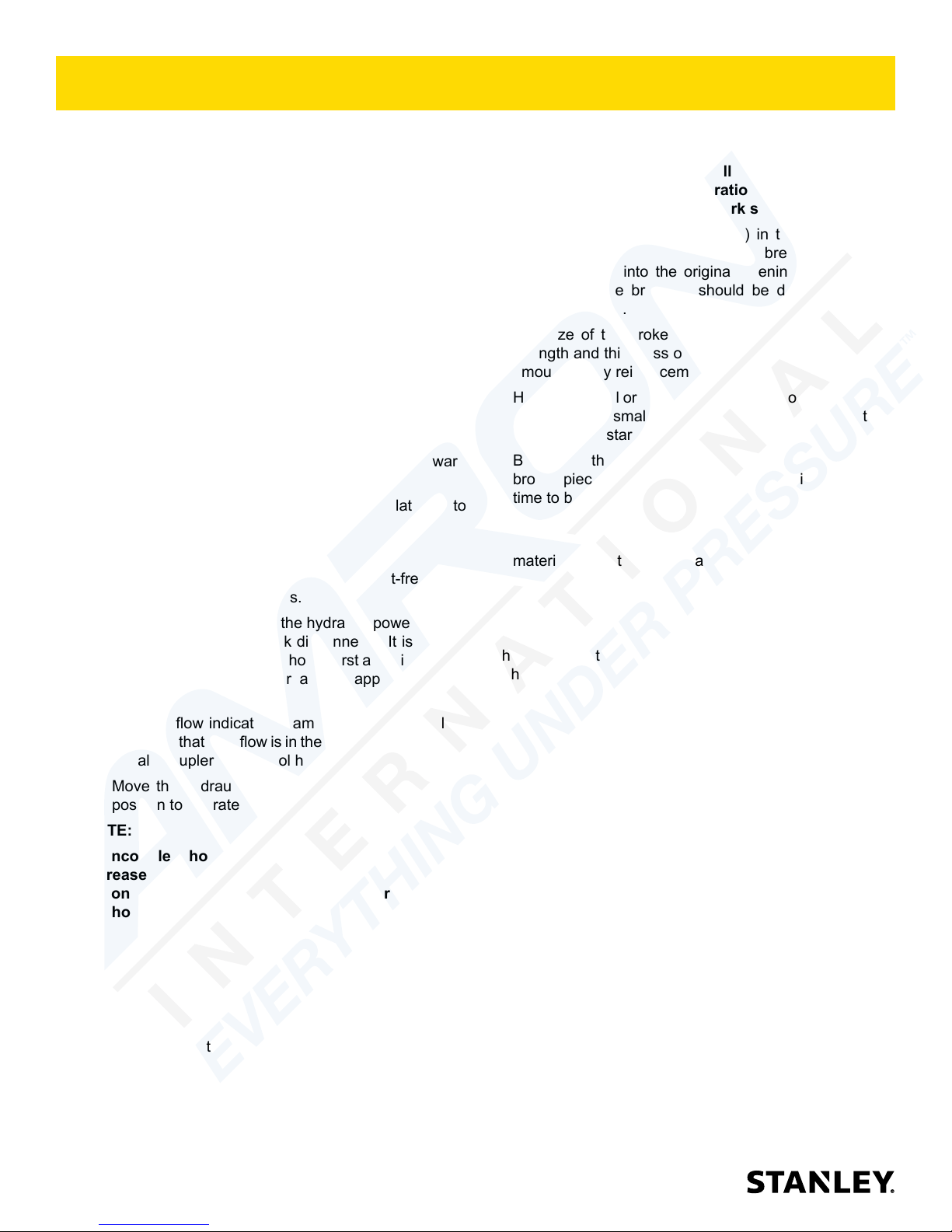
CONNECT HOSES
1. Wipe all hose couplers with a clean, lint-free cloth
before making connections.
2. Connect the hoses from the hydraulic power source
to the tool ttings or quick disconnects. It is a good
practice to connect return hoses rst and disconnect
them last to minimize or avoid trapped pressure
within the tool.
3. Observe ow indicators stamped on hose couplers
to ensure that uid ow is in the proper direction. The
female coupler on the tool hose is the inlet coupler.
4. Move the hydraulic circuit control valve to the ON
position to operate the tool.
NOTE:
If uncoupled hoses are left in the sun, pressure
increase within the hoses may make them difcult
to connect. When possible, connect the free ends of
the hoses together.
NOTE:
Partially depressing the trigger allows the tool to run
at slow speed. Slow-speed operation permits easier
starting of the tool bit into the work surface.
5. To start, break an opening (hole) in the center of
the surface. After making a hole, break portions
of the material into the original opening. For best
productivity, the breaking should be done around
the original hole.
The size of the broken material will vary with the
strength and thickness of the base material and the
amount of any reinforcement wire or rebar.
Harder material or more reinforcing wire or rebar will
require taking smaller bites. To determine the most
effective bite, start with 2 in. / 50 mm or smaller bites.
Bites can then be gradually increased until the
broken piece becomes too large, requiring increased
time to break off the piece.
Sticking of the tool bit occurs when too large a bite
is being taken and the tool bit hammers into the
material without the material fracturing. This causes
the tool bit to become trapped in the surrounding
material.
COLD WEATHER OPERATION
If the breaker is to be used during cold weather, preheat
the hydraulic uid at low engine speed. When using the
normally recommended uid, uid temperature should
be at or above 50 °F/10 °C (400 ssu/82 centistokes)
before use.
Damage to the hydraulic system or breaker can result
from use with uid that is too viscous or thick.
OPERATION PROCEDURES
1. Observe all safety precautions.
2. Install the appropriate tool bit for the job.
3. Place the bit rmly on the surface to be broken.
4. Squeeze the trigger to start the breaker. Adequate
down pressure is very important. When the tool bit
breaks through the obstruction or becomes bound,
release the trigger and reposition the tool bit.
10 ► BR45 User Manual
 Loading...