

Page 1
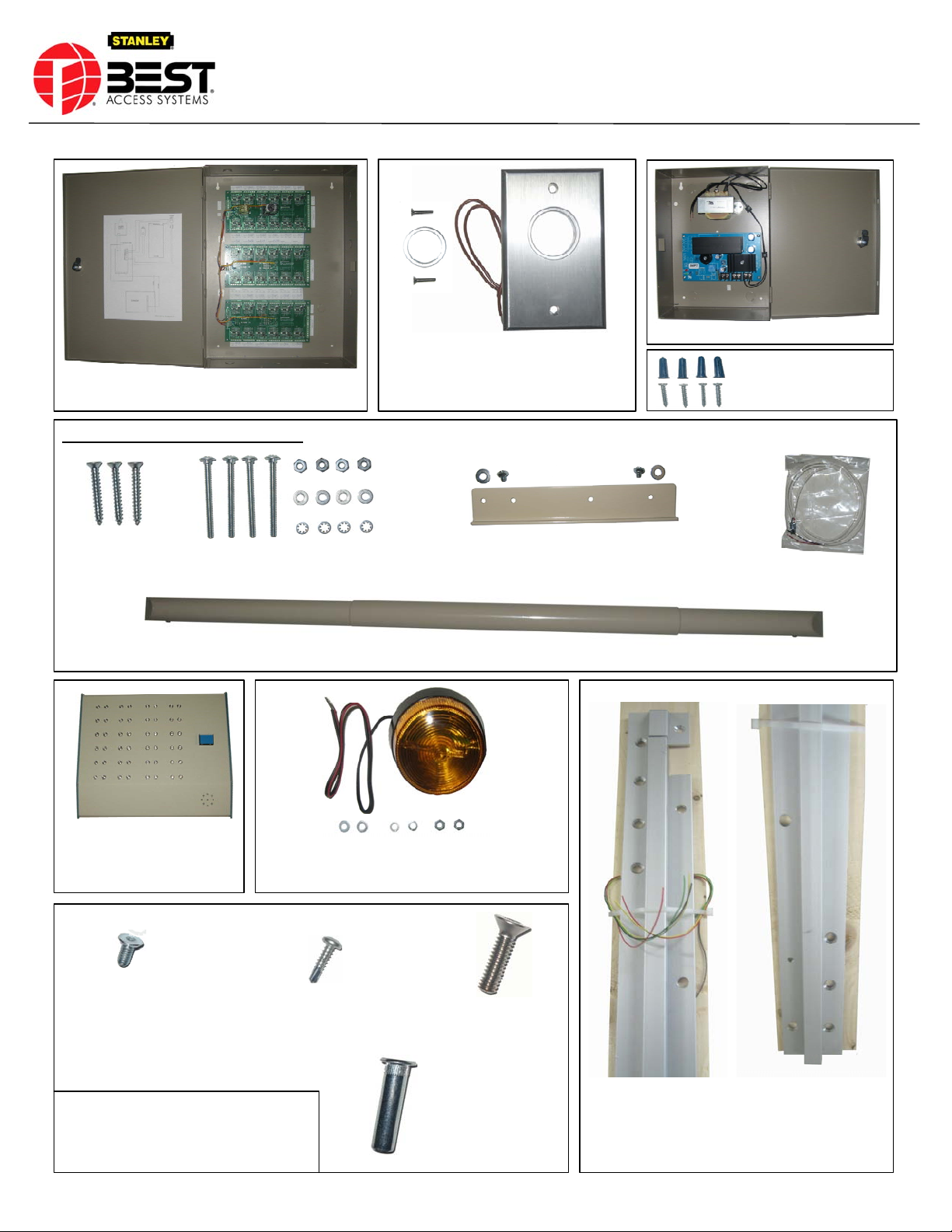
Controller x 1 each
Telescoping Sensor & Fasteners
SSS-SEDA (Emergency Door Alarm)
6 – 32 x ½” Flat Head Security Screw x 2
each, Cylindrical Locking Ring x 1 each &
Re – Set Key Switch x 1 each
Packing List
Power Supply x 1 each
#8 Wood Screws & Plastic
Anchors x 8 each
# 8 Wood Screws
x 3 each
Console x 1 each
12-24 x ½” Torx Flat
Head Screw x 15 each
10-24 Carriage Bolt, Hex Nuts,
Washers & Lock Washers x 4 each
Flashing Amber Light x 1 each &
#10-32 Nuts, Split Washer & Flat Washer x 2 each
#10-¾” self Drilling Screw
X 4 each
8 – 32 x 3/16" Pan Head Phillips Screws, #8 Washers x 2
each & Mounting Plate Spacer x 1 each
Telescoping Sensor x 1 each
¼ - 20 x 1" Torx Flat
Head Screw
x 9 each
Top Portion
Wire Harness x 1 each
Bottom Portion
BEST ACCESS SYSTEMS
A Product Line of Stanley Security Solutions, Inc
Indianapolis, IN - 46250
(800)-392-5209
INS SSS-SEDA v6.0.vsd Created: 9/23/2009 Revised:5/27/2010 INS0000130-01 v1.0 Page 1
¼ - 20 x 1-5/8" Sex Bolt
x 9 each
Full Mortise Hinge x 1 each
Page 2
SSS-SEDA (Emergency Door Alarm)
NOTE:
SEDA Door Sensors are provided to match the door width provided.
INSTALLATION INSTRUCTIONS:
FULL MORTISE HINGE
See Separate sheet provided for installation instructions.
POWER SUPPLY / CONTROLLER
Install the Power Supply / Controller. Connect console to it. Power up the controller.
All LED’s should turn green. Install each door individually as follows
Installation Instructions
Telescoping Sensor
STROBE
PULL SIDE OF THE DOOR
Mount on ceiling and run wires to Controller.
Observe Polarity Red “+” and Black “-“.
KEY SWITCH
Add mortise cylinder (straight Yale cam).
Mount on single gang box at door and run wires to Controller. Key switch is “NC”, system can not work without it.
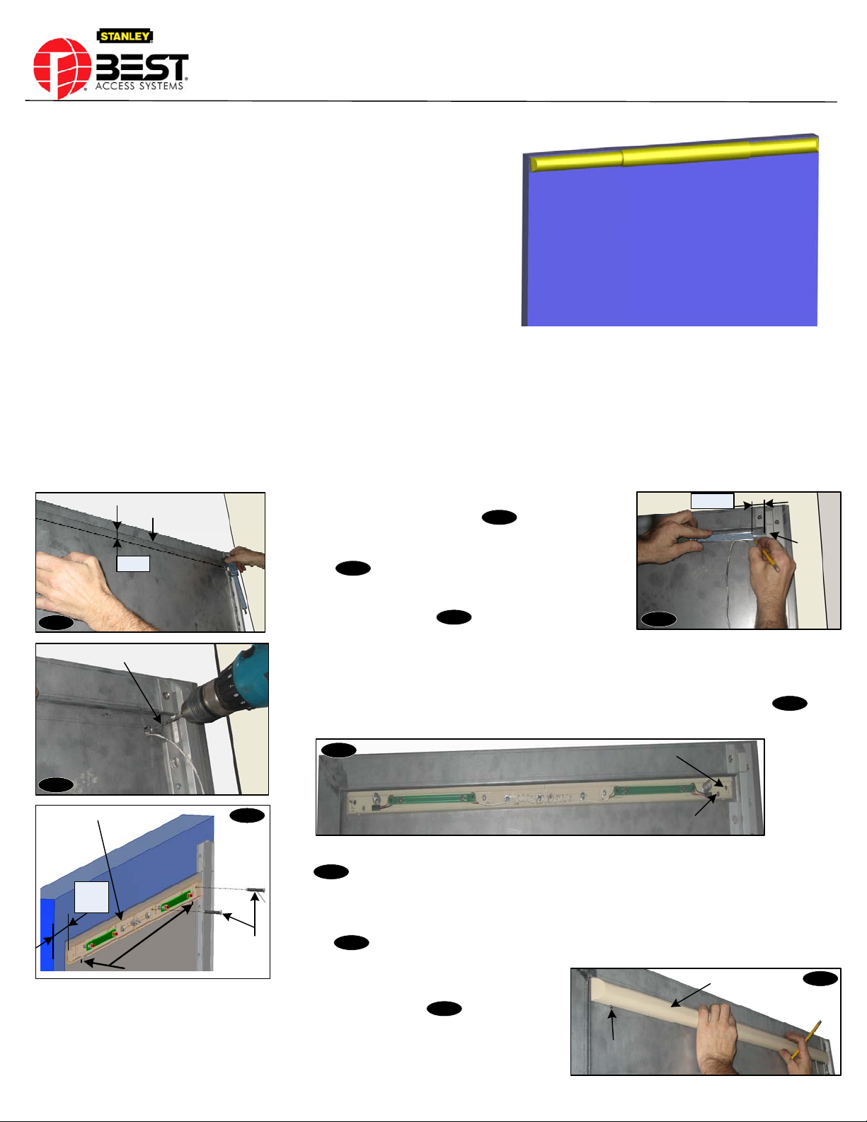
DOOR SENSOR
Please Read Completely Before Starting
1) Mark a horizontal line ¾” from the top of the door and extend to
H
o
Fig-1
Top edge of the door
r
i
z
o
n
t
a
l
L
i
n
e
F
r
a
m
e
¾”
Door
Pilot Hole
the lock edge of the door as shown in .
Fig-1
2) Mark a vertical line 1-1/8" from the notched edge of the hinge as
shown in .
Fig-2
3) Mark center point at horizontal and vertical line intersects. Drill
pilot hole of 1/8" as shown in .
Fig-3
4) Loosen sensor cover screws enough to enable removal of the sensor cover form the mounting plate.
Loosen sensor adjustment nuts.
5) Place sensor mounting plate on the door with first mounting hole over pilot hole as shown in . Pull
out wire from wiring hole.
Frame
Fig-2
1-1/8"
Door
Notched edge of the Hinge
Fig-4
Door
Fig-3
Sensor Mounting Plate
shown in .
3/8"7/16"
Lock Edge of the Door
Door
Self – Tapping / Wood
Slot Provided
Fig-5
Screws
Fig-4
Sensor Mounting Plate
6) Temporarily secure the hinge side sensor mounting plate on door with two self-tapping / wood screws as
Fig-5
7) Loosen adjustment nuts on mounting plate and Slide the sensor mounting plate towards the lock edge of
the door so that there is no more than 3/8"-7/16" gap between the sensor mounting plate & the lock edge as
shown in .
Fig-5
8) Line up the cover screws of the sensor cover with
the slots provided on the sensor mounting plate. Adjust the sensor cover as needed. Attach sensor cover
to the mounting plate and loosely tighten the cover screw provided as shown . (Make sure the top
Fig-6
First Mounting Hole
Wiring Hole
Sensor Cover
of the cover extends no more than 1/8” above the top of the door).
Cover screw
Test the operation of the sensor.
INS SSS-SEDA v6.0.vsd Created: 9/23/2009 Revised:5/27/2010 Page 2
Door
Fig-6
Page 3

SSS-SEDA (Emergency Door Alarm)
Installation Instructions
9) Remove the sensor cover. Mark the locations of the lock side mounting holes, and remove entire assembly from the door.
10) Prepare each of the (4) mounting hole locations for thru-bolting: drill .201 (#7 Drill) holes at each locations.
11) Install mounting plate with (4) four 10-24 x 2" carriage bolts, #10 lock washers and hex nuts provided as shown in .
Hex Nuts
Lock Washers Lock Washers
Fig-7
10 – 24 x 2" Carriage Bolts
Fig-7
Hex Nuts
12) Optional Step: If necessary cut the mounting plate spacer to the size and fill the gap between lock side and hinge side mounting plates. Secure it
through slot with 8-32 Pan head Phillips screws and #8 Lock washers as shown in .
Fig-8
8 – 32 x 3/16" Pan Head Phillips
Screws x 2 each
Mounting Plate Spacer
13) Tighten adjustment nuts on mounting plate and cover.
14) Attach the quick connect plug to the wire receptacle on the sensor as shown in .
Fig-8
#8 Lock Washers
x 2 each
Fig-9
Fig-9
15) Secure sensor cover to the mounting plate with (2) #5 cover screws as shown in .
Fig-10
#5 Cover Screws
Fig-10
Quick connect Plug
Fig-11
Allen Head Screws
16) Test the operation. Press the sensor cover to check the sensitivity of the sensor. If more sensitive then detach the sensor cover and loosen the both
allen head screws as shown in . Adjust the allen head screws as needed (Tighten the screw for less sensitivity and loosen the screw for more
Fig-11
sensitivity). Sensor switches are “NO”. Connect sensor to the controller.
17) LED of console should stay green. If it turns red itself, sensor should be adjusted for less sensitivity.
18) Hold the sensor and depress for 3 sec or longer. LED should turn into red. If not, sensor should be adjusted for more sensitivity.
19) Test the operation again. If good, apply blue LOCTITE® for safety to the screws and install.
BEST ACCESS SYSTEMS
A Product Line of Stanley Security Solutions, Inc
Indianapolis, IN - 46250
(800)-392-5209
INS SSS-SEDA v6.0.vsd Created: 9/23/2009 Revised:5/27/2010 Page 3
Page 4

SEDA Wiring Information
POWER
SUPPLY
DC 12V
+ -
+ -
POWER IN
110 VAC
+ 12V ALARM
OPTIONAL REMOTE
C
OUTPUT
NC NO
SENSOR
KEY
DOOR 1
STROBE
LIGHT
SENSOR
KEY
SWITCH
“NC”
“NO”
BLACK
RED
DOOR
SWITCH
CONTROLLER
S12S11S10S9S8S7S6S5
CONSOLE
S4 S3 S2 S1
+ -
STROBE
CONSOLE
AL
SILENCE
-
+
CONSOLE
SEDA SCHEMATIC. REVISED 05/27/2010
BEST ACCESS SYSTEMS
A Product Line of Stanley Security
Solutions, Inc
Indianapolis, IN - 46250
(800)-392-5209
AL SILENCE
+
-
S1
S4 S3 S2
S12 S11 S10 S9 S8 S7 S6 S5
 Loading...